1
DCMS
Display Consistency
Management Software
User Manual
K5960008-03
Intentionally left blank
2 ___________________________________________________________Barco - DCMS - User Manual
About
1
About
1.1
Contents of the user manual
This guide consists of the following chapters:
Chapter 1: About
Chapter 2: Important notice
Chapter 3: About DCMS
Chapter 4: Installing DCMS
Chapter 5: Connecting the components
Chapter 6: Running the DCMS application
Chapter 7: Display connection and calibration options
Chapter 8: Calibration process
Chapter 9: Verification
Chapter 10: The log file
Chapter 11: List of abbreviations
Chapter 12: Appendix A: Open Source Software
Chapter 13: Appendix B: Specifications
1.2
Change record
Revision
Date
Description
00
March-08
Initial Release
01
May-08
Added/changed RS232 connection issues
02
July-09
Added NSL-4601
03
April-10
Software update V1.03
Barco - DCMS - User Manual __________________________________________________________ 3
About
1.3
Notation convention
Following notations are applicable to this manual and should be respected
through the manual.
WARNING:
Warnings – presented in this manual, provide information, which if not adhered to, may result
in personal injury or death.
CAUTION:
Cautions – presented in this manual, provide information, which if not adhered to, may result
in damage to the equipment.
NOTE:
Notes – presented in this manual, provide information, which emphasize points, significant to
understand and operate the unit.
IMPORTANT:
Important – presented in this manual, provide information, which is important to highlight.
4 ___________________________________________________________Barco - DCMS - User Manual
Important notice
2
Important notice
2.1
Commercial In Confidence
The information contained herein is Barco confidential information. No part of
the information contained herein may be disclosed outside of the organization of
the recipient, its sub-contractors, and customers in any form or by any means
and/or stored in a database or retrieval system without the prior written consent
of Barco.
2.2
Copyright
This document is copyrighted. All rights are reserved. Nor this document, nor
any part of it, may be reproduced or copied in any form or by any means graphical, electronic, or mechanical including photocopying, taping or
information storage and retrieval systems - without written permission of Barco.
© Barco N.V. All rights reserved.
2.3
Open Source Software
The RXTXComm library used to communicate over RS232 is Open Source. The
library carries the RXTX License (http://users.frii.com/jarvi/rxtx/license.html),
which is a modified LGPL 2.1. LGPL can be found at http://www.gnu.org/
licenses/lgpl.txt. The RXTX library is included in its whole (including sources) to
the DCMS CD-ROM.
The RXTX extension to the LGPL is for completeness listed in appendix A.
2.4
Embedded pictures
NOTE:
The pictures embedded in this document are for illustration purposes only and may look
different depending on the device used to visualize this document (printer, display, …).
2.5
Product safety notice
CAUTION:
Check the documentation of your display before physically connecting the monitor. Check that
the cable you are about to use is fit for use with your monitor.
Barco - DCMS - User Manual __________________________________________________________ 5
Important notice
2.6
Software License Terms
1 This Software License is between you and BARCO NV, a corporation organized
and existing under the laws of Belgium registered under number BE
0473.191.041, Commercial Companies' Register of Kortrijk, having its registered
office President Kennedypark, 35 at B-8500 Kortrijk, Belgium ("Barco") for the
use of the Software.
2 The Display Consistency Management Software and related documentation
which are supplied herewith (together "Software") and the relating USB Sensor
(“Materials”), used to operate the equipment identified in the documentation
(“Equipment”), is licensed to you under this software license agreement
("Software License"), for use by any persons employed by or otherwise
authorized by you ("Authorized Users"), subject to the use limit stated herein
and accepted by you when agreeing to enter into this License.
You must read this Software License and agree to their terms before you may
install and run the Software that has been supplied to you. You indicate YOUR
ACCEPTANCE of this Software License by breaking the seal on the CD wallet and/
or arranging for installation of the Software, and/or by proceeding to run the
Software. If you do not accept the terms set out in this Software License, please
return the software to Barco NV ("Barco") or the appointed Barco reseller who
sold the Software to you and, as appropriate, discontinue the use of the
Software.
3 The Software is intended to be used to calibrate the displays identified in the
documentation and you agree to limit the use of the Software for such intended
purpose. You hereby undertake to inform all Authorized Users of the terms of
this Software License and to bind all Authorized Users to accept all such terms of
this Software License as applies to them. In consideration of payment of the
agreed upon license fees, Barco grants you a limited, non-exclusive, nonassignable, non-transferable license (without the right to grant sublicenses) and
right to use the Software by you and/or any Authorized User(s) to operate the
Equipment.
4 Barco (and Barco's licensors, as appropriate) retain ownership of all
intellectual property rights in the Software and any copies you or any Authorized
User may make of such Software. The Software is protected by national
copyright laws, international copyright treaties and conventions, and other
applicable laws. All rights not expressly licensed to you in this Software License
are reserved to Barco and Barco's licensors, as appropriate. The Software
contains certain other licensed materials (and including open source software)
and Barco's licensors may protect their rights in the event of any violation of this
Software License. Neither you nor any Authorized User may, whether in whole or
in part, copy, translate, reverse engineer, derive source code from, modify,
disassemble, decompile, create derivative works based on the Software, or
remove any proprietary notices or labels on the Software, save as may be
permitted by law, under the open source software license terms or this Software
License, without the prior consent, in writing, of Barco.
5 You and Authorized Users are entitled to use the Software for the purposes
and in the manner set out herein, but neither you nor any Authorized User are
entitled to: (i) sell or grant a security interest in the Software to other parties in
any way, or to rent, lease or sub-license the Software to others without the
express prior written consent of Barco; or (ii) exploit the Software or any of its
component parts for any commercial purpose, other than use by you and/or
Authorized Users of the Software as an ancillary visualization platform for
computer integrated manufacturing data.
6 The duration of this Software License will be from the date of your acceptance
(as set forth above) of the Software, with no termination date, unless otherwise
specified. You may terminate this Software License at any time by destroying all
6 ___________________________________________________________Barco - DCMS - User Manual
Important notice
copies of the Software then in your possession and returning all associated
materials and documentation, to Barco or the appointed Barco reseller that sold
or provided these to you. Barco may terminate this Software License forthwith
by informing you at any time if you and/or any Authorized User are in breach of
any of the Software License's terms.
7 Barco warrants that (a) the Software will perform substantially in accordance
with the accompanying written materials for a period of three (3) months from
the date of your receipt of the Software (the "Warranty Period"), and (b) the
Materials which may accompany the Software will be free from defects in
materials and workmanship under normal use and service for a period of twelve
(12) months from the date of your receipt of the Software and Materials.
You acknowledge that the Software is a complex computer software application,
and that the performance thereof may vary depending hardware platform,
software interactions and configuration. You acknowledge that the Software is
not designed and produced specifically to meet your specific requirements and
expectations and the selection of the Software by you is entirely your own choice
and decision.
8 Except for the open source software incorporated in or delivered with the
Software, Barco shall hold you harmless and indemnify you from and against
direct damages, losses and expenses arising from infringement or alleged
infringement of any patent, trademark or copyright of such third party by the
license and the right to install the Software as permitted by this Software
License and defend and settle at its sole expense any claim, action, suit or
proceeding brought against you, provided that (i) you promptly notify Barco in
writing after a claim has been asserted against you or the commencement of
any claim, action, suit or proceeding, and (ii) Barco shall assume sole control of
the defense and any settlement negotiations related to any claim, action, suit or
proceeding, and (iii) you shall not negotiate, settle or compromise any claim,
action, suit or proceeding without the prior written consent of Barco and (iv)
you, at your cost, shall cooperate with Barco and provide assistance and
support, as may reasonably required by Barco, in connection with the defense
and any settlement negotiations related to any claim, action, suit or proceeding.
Barco shall have no indemnity obligation for any Software, or any portion
thereof, (i) that is based on specifications, drawings, models or other data
furnished by you or, (ii) that is not provided by Barco or, (iii) that is modified, in
spite of the prohibition for you to modify the software or, (iv) to the extent that
you continue allegedly infringing activity after having been provided
modifications that avoid the alleged infringement, or (v) where the use of the
Software, or the combination or thereof with other products, processes or
materials or the distribution thereof rather than the Software itself is the
primary cause of an alleged infringement. In case it has been determined by a
finally awarded judgment that Barco infringed or misappropriated such third
party rights or earlier, at Barco's discretion, it may, at its option and cost, (i)
modify the Software in such a way that it shall not infringe upon or
misappropriate the rights of the third party or (ii) obtain for you a license or
other right to use the rights allegedly infringed or (iii) replace the Software in
question with non-infringing Software. The remedies set forth in this paragraph
shall constitute your sole and exclusive remedy and Barco's sole and exclusive
liability for a third party claim that the Product infringes or misappropriates any
intellectual property right of a third party.
9 YOU UNDERSTAND THAT THE SOFTWARE IS BEING PROVIDED TO YOU "AS IS"
WITH ONLY A LIMITED WARRANTY AS SET OUT IN CLAUSES 7 AND 8 HEREOF.
BARCO DOES NOT MAKE NOR INTENDS TO MAKE ANY OTHER WARRANTIES OR
REPRESENTATIONS, EXPRESS OR IMPLIED AND SPECIFICALLY DISCLAIMS ALL
IMPLIED WARRANTIES OF MERCHANTABILITY FITNESS, FOR A PARTICULAR
PURPOSE AND NON-INFRINGEMENT OF INTELLECTUAL PROPERTY AND DOES
NOT WARRANT THAT THE SOFTWARE WILL BE FREE FROM ERRORS OR THAT
Barco - DCMS - User Manual __________________________________________________________ 7
Important notice
SUCH ERRORS WILL BE CORRECTED BY BARCO AND YOU ARE SOLELY
RESPONSIBLE FOR ALL COSTS AND EXPENSES ASSOCIATED WITH
RECTIFICATION, REPAIR OR DAMAGE CAUSED BY SUCH ERRORS.
YOU ALSO ACKNOWLEDGE AND AGREE THAT:
(i) BARCO ACCEPTS NO LIABILITY FOR ANY DAMAGES, LOSSES OR CLAIMS YOU
OR ANY THIRD PARTY MAY SUFFER AS A RESULT OF YOUR USE OF THE
SOFTWARE, AND YOU HEREBY AGREE TO INDEMNIFY, KEEP INDEMNIFIED,
DEFEND AND HOLD HARMLESS BARCO AND BARCO'S AFFILIATES AND
SUBSIDIARIES FROM AND AGAINST ANY AND ALL ACTIONS, PROCEEDINGS,
LIABILITY, LOSS, DAMAGES, FEES AND COSTS (INCLUDING ATTORNEYS' FEES),
AND OTHER EXPENSES INCURRED OR SUFFERED BY BARCO ARISING OUT OF
OR IN CONNECTION WITH ANY BREACH BY YOU OF THE TERMS OF THIS
SOFTWARE LICENSE. TO THE MAXIMUM EXTENT PERMITTED BY LAW, IN NO
EVENT WILL BARCO BE LIABLE FOR ANY INDIRECT, SPECIAL, PUNITIVE,
INCIDENTAL OR CONSEQUENTIAL LOSS OR DAMAGES OF ANY KIND WHICH
MAY ARISE OUT OF OR IN CONNECTION WITH THE SOFTWARE, THIS
SOFTWARE LICENSE OR THE PERFORMANCE OR PURPORTED PERFORMANCE OF
OR FAILURE IN THE PERFORMANCE OF BARCO'S OBLIGATIONS UNDER THIS
SOFTWARE LICENSE OR FOR ANY ECONOMIC LOSS, LOSS OF BUSINESS,
CONTRACTS, DATA, GOODWILL, PROFITS, TURNOVER, REVENUE, REPUTATION
OR ANY LOSS ARISING FROM WORK STOPPAGE, COMPUTER FAILURE OR
MALFUNCTION OF THE SOFTWARE AND ANY AND ALL OTHER COMMERCIAL
DAMAGES OR LOSSES WHICH MAY ARISE IN RESPECT OF USE OF THE
SOFTWARE, EVEN IF BARCO HAS BEEN ADVISED OF THE POSSIBILITY OF THEIR
OCCURRENCE; AND
(ii) YOU ACKNOWLEDGE THAT NO WARRANTY IS GIVEN BY BARCO ON THE
OPEN SOURCE SOFTWARE INCLUDED IN THE SOFTWARE; AND
(iii) BARCO'S SOLE LIABILITY AND YOUR SOLE REMEDY UNDER THIS
SOFTWARE LICENSE SHALL BE THE REPLACEMENT OF THE SOFTWARE IF ANY
CD-ROM CARRYING THE SOFTWARE OR THE MATERIAL IS PROVEN TO BE
DEFECTIVE BY BARCO'S PERSONAL INSPECTION, IN EACH CASE WITHIN THE
PERIOD SET OUT IN CLAUSE 7, FOLLOWING INSTALLATION.
10 Each party shall treat as confidential all information obtained from the other
pursuant to this Software License which is marked 'confidential' or the
equivalent or has the necessary quality of confidence about it and shall not
divulge such information to any persons (except to such party's own employees
or agents and then only to those employees or agents who need to know the
same and are obligated in writing to confidentiality at least to the same extent
as provided herein) without the other party's prior written consent provided that
this Paragraph 6 shall not extend to information which was rightfully in the
possession of such party prior to the commencement of the negotiations leading
to this Software License, which is already public knowledge or becomes so at a
future date (otherwise than as a result of a breach of this paragraph 10), is
required to be disclosed by law or which is trivial or obvious. Each party shall
ensure that its employees are aware of and comply with the provisions of this
paragraph 10. The foregoing obligations as to confidentiality shall survive any
termination of this Software License.
11 This Software License (and documentation which is hereby integrated
herewith) is the only understanding and agreement between you and Barco for
use of the Software by you and/or Authorized Users. The Software License
supersedes all other communications, understandings or agreements we had
prior to this Software License (with the exception of any continuing
confidentiality agreement) although nothing in this Software License purports to
exclude liability for fraudulent misrepresentation. You may not export or reexport the Software or any copy or adaptation in violation of any applicable laws
or regulations. Neither this Software License shall be altered, amended or varied
save by an instrument in writing executed by duly authorized representatives of
8 ___________________________________________________________Barco - DCMS - User Manual
Important notice
both parties. Except as otherwise expressly provided for in this Software
License, no forbearance, delay or indulgence by either party in enforcing the
provisions of this Software License shall prejudice or restrict the rights of that
party, nor shall any waiver of such parties rights operate as a waiver of any
subsequent breach, and no right, power or remedy herein conferred upon or
reserved for either party, is exclusive of any other right, power or remedy
available to that party and each such right, power or remedy shall be
cumulative. If any provision of this Software License is determined by the parties
to be illegal, void or unenforceable, or if any court of competent jurisdiction in
any final decision so determines, this Software License shall continue in full force
save that such provision shall be deemed to be deleted with effect from the date
of such decision, or such earlier date as the parties may agree.
12 The construction, validity and performance of this Software License shall be
governed in all respects by the laws of Belgium without recourse to its conflict of
law principles. All disputes arising in any way out of or affecting this Software
License shall be subject to the exclusive jurisdiction of the courts of Kortrijk, to
which the parties agree to submit, without prejudice to enforcement of any
judgment or order thereof in any other jurisdiction.
13 The United Nations Convention on Contracts for the International Sale of
Goods (the "Convention") shall not apply to this Software License, however, if
the Convention is deemed by a court of competent jurisdiction to apply to this
Software License, Barco shall not be liable for any claimed non-conformance of
the Software under Article 35(2) of the Convention.
Barco - DCMS - User Manual __________________________________________________________ 9
About DCMS
3
About DCMS
3.1
What is DCMS?
The Barco Display Consistency Management Software (DCMS) is a software tool
to calibrate displays in terms of luminance, gamma and gray tracking*. DCMS is
able to calibrate displays to a predefined set of parameters or match displays to
each other. The software uses a USB color sensor to measure color and
luminance.
The term Display Consistency applies to the consistency of color throughout the
gray scale and the consistency of color and luminance between multiple displays
of the same or different type.
*Gray
tracking means that the color of every gray level from black to white is
constant, and equal to the white point target. In practice, because of LCD
limitations, this holds for gray levels higher than 20% drive.
3.2
Why using DCMS?
Because of spread in backlight, color filter and liquid crystal properties, all LCDs
have different native white points and gamma. The same user settings will
effectively produce different images, visible when the displays are put next to
each other. Appropriate calibration can solve this by matching the luminances,
gammas and white points.
This calibration requirement is general for all markets that use tiled LCD
displays. More specifically, broadcasters must be able to trust the color they are
seeing, so as good as possible absolute calibration (to an absolute, defined
target) is also necessary. This is a matter of cost – used sensor, bit-depth of
display and electronics, cost of color correction software and cross-talk removal,
spread of color filters etc.
DCMS consists of software and sensor performing the given calibration.
10 __________________________________________________________Barco - DCMS - User Manual
About DCMS
3.3
Key components
3.3.1
Calibration system
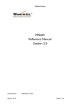
Calibration with internal test pattern generation (without disconnecting
the display from its source)
The calibration can be done without disconnecting the display. In this case, a
laptop or desktop PC is needed to run the DCMS software. This laptop/PC needs
to be connected to the RS232 service port of the display. The USB color sensor
should be connected to the laptop/PC. The internal test pattern generator of the
display is used to create the colored fields needed for the calibration.
USB
DVI
RS232
Figure 1: External calibration system
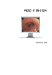
Calibration with external computer graphics (by using the input source
as calibration system)
Another way of setting up the calibration system is by using the input source as
calibration system. The computer is connected to the display via RS232 and the
color sensor is connected via USB. In this scenario, the colored test fields are
generated as computer graphics.
For this, the display needs to be connected through DVI and driven at native
resolution at 24 bits per pixel color depth.
USB
RS232
DVI
Figure 2: The input source as part of the calibration system
There is no difference in calibration results between the two calibration systems.
Barco - DCMS - User Manual _________________________________________________________ 11
About DCMS
IMPORTANT:
When calibration is done with external computer graphics, please restore all color settings of
the host’s graphics controller to their default value and disable any host services that may
affect the color of the output picture.
3.3.2
Display
Each pixel of the display has 3 sub-pixels. These sub-pixels each have a color
that corresponds with the three wavelengths for which the human eye is the
most sensitive. These colors are red, green and blue (RGB). Each of these subpixels typically has 256 discrete levels. Colors are reproduced by combinations
of these three primary colors.
Gamma is the perceptual linearity of light. Gamma is expressed by a power
function.
Color temperature (or white point) is the ‘color’ of white. We say that the display
has a warm white point or color temperature if the white of the display is
reddish. The display has a cold or cool white point or color temperature if the
white of the display is bluish. The color temperature or white point is expressed
as coordinates in a color space (for example: xy values in CIE1931xyY space) or
the temperature in degrees Kelvin at which a black body gets this color.
Contradictory, we speak of warm white when the color temperature is low (for
example: 3200K) and cold white when the color temperature is high (for
example: 9300K). Daylight has a color temperature of 6500K.
Gray tracking is keeping the color temperature constant for all gray levels
between black and white.
The brightness (light intensity of full white) is also calibrated as the power
applied to the backlights. If the brightness target is set lower than the dimming
capabilities of the backlight driver then additional dimming can be applied in the
video if the display supports this function.
3.3.3
Sensor
The sensor used for calibration is the Barco USB color sensor (not sold
separately). This sensor has a USB interface to the host PC running the DCMS
application. Accuracy of the sensor is < 0.005 xy in CIE1931xyY color space.
Luminance accuracy is < 5%. The sensor is shipped with a suction cap to attach
the sensor to the monitor and a pod for dark current calibration of the sensor.
12 __________________________________________________________Barco - DCMS - User Manual
About DCMS
3.4
Package content
•
USB color sensor (Marked ‘Configured for DCMS’)
•
RS232 cable male-female, 3-wire straight, 1.8m
•
RS232 cable male-female, 3-wire crossed, 1.8m
•
Calibration sheet of the sensor
•
Sensor pod for sensor calibration
•
Contra weight for sensor
•
Felt cup to prevent damage to displays without front glass
•
Suction cup for attaching sensor to front glass of display
•
CD-ROM containing DCMS software
•
CD-ROM containing DCMS User Manual
•
Installation manual
•
DCMS license certificate
Barco - DCMS - User Manual _________________________________________________________ 13
Installing DCMS
4
Installing DCMS
4.1
System requirements
4.2
4.3
•
Host: Pentium II or later
•
Memory: 256MB
•
Hard disk space: 80MB (including Java Run-Time Environment)
•
Drives: CD-ROM + HDD
•
Operating system: Windows XP
•
Run-Time Environments: Java SE 1.5 minimum (installed with DCMS)
•
Boards & drivers: Driver for USB Optisense color sensor is available in the
installation folder.
•
Display: DVI capable of driving the display at its native resolution in 24bpp
(optional)
•
Other peripherals: USB, RS232
Before installing DCMS
•
You must have Administrator privileges to install the software
•
If there are older versions of DCMS installed, remove them first. Refer to the
paragraph “Uninstalling DCMS” further in this chapter.
Installing DCMS
The DCMS software installer is available as an executable ‘install.exe’ in the
following folder on the installation CDROM: Disk1\InstData\VM.
The DCMS installer is a standard application installer which guides you through
the installation and gives the option to go to the next window, go back to the
previous window or cancel the installation at any time.
To install the DCMS software, follow these steps:
•
Double click the ‘install.exe’
The installer unpacks the necessary files. A dialog with progress bar is displayed.
14 __________________________________________________________Barco - DCMS - User Manual
Installing DCMS
•
Introduction
Read the introduction and press ‘Next’ to continue.
It is strongly recommended to quit all programs before continuing with the
installation. If you want to change something on a previous screen, click the
‘Previous’ button. The installation can be cancelled by clicking the ‘Cancel’
button.
•
License Agreement
Read and accept the Software License Terms.
As long as the licence agreement is not accepted, the installation process cannot
be continued. Press ‘Next’ to continue.
Barco - DCMS - User Manual _________________________________________________________ 15
Installing DCMS
•
Enter License Key
To continue the installation, enter your personal License Key, supplied on the
DCMS license certificate. Press ‘Next’ to continue.
•
Choose Install Folder
Type or choose (with the folder browser) a location to install DCMS. The default
location is ‘C:\Program Files\Barco\DCMS’. By pressing the ‘Restore Default
Folder’ button, you can always reset the default location.
Press ‘Next’ to continue.
16 __________________________________________________________Barco - DCMS - User Manual
Installing DCMS
•
Choose Shortcut Folder
Choose the location where the shortcuts will be located. There is a shortcut
available for the DCMS application in the Barco DCMS program Group.
It is also possible to skip the creation of shortcuts.
Press ‘Next’ to continue.
•
Pre-Installation Summary
This window gives a summary of the selected/specified options. This panel gives
the user the chance to review the settings before starting the actual installation.
To start the actual installation, press ‘Install’.
Barco - DCMS - User Manual _________________________________________________________ 17
Installing DCMS
•
Installing…
During the installation, a dialog with progress bar is displayed.
•
Install Complete
The Install Complete panel shows if the installation was successful or not. If not
successful, the installer will refer to the installation log for more details.
18 __________________________________________________________Barco - DCMS - User Manual
Installing DCMS
4.4
Uninstalling DCMS
To remove DCMS from your system:
•
Be sure you have Administrator privileges to uninstall the software
•
Exit the DCMS program
•
From the Start menu, select Settings > Control Panel
•
Double-click the Add/Remove Programs icon
•
Select DCMS from the list box
•
Click the Add/Remove… button
Barco - DCMS - User Manual _________________________________________________________ 19
Installing DCMS
•
Click the Uninstall button to remove the DCMS program.
NOTE:
Log files and files containing calibration parameters are not automatically removed.
20 __________________________________________________________Barco - DCMS - User Manual
Connecting the components
5
Connecting the components
5.1
Optical sensor connection
CAUTION:
The USB sensor is delivered with a suction cup head that can be attached to the sensor for
easy attachment to a display with front glass. The use of this suction cup on displays without
front glass is not advised. Therefore a felt cup head is also delivered.
If you decide to use the suction cup head despite this warning, be sure to turn the sensor when
removing the sensor from the LCD and do not pull it off perpendicular to the LCD.
To change the sensor head:
•
Remove the suction cup head by turning the head adapter in counterclockwise sense as illustrated below.
•
Place the felt cup sensor head on the sensor and turn the head adapter in
clockwise sense.
Figure 3: Sensor head removal
To connect the sensor:
•
Plug in the sensor in one of the USB connectors of your PC. See also ‘Calibration system connections’ paragraph below.
•
Windows pops up a message box ‘Found new hardware’
Barco - DCMS - User Manual _________________________________________________________ 21
Connecting the components
•
Select ‘No, not this time’ and click ‘Next’ to continue.
•
Select ‘Install the software automatically’ and click ‘Next’ to continue.
22 __________________________________________________________Barco - DCMS - User Manual
Connecting the components
•
Browse to the path where the file ‘seqcal.sys’ is located and click ‘OK’.
If the DCMS is successfully installed, the file should be available in the subfolder ‘drivers’ of the installation folder on your hard disk.
Barco - DCMS - User Manual _________________________________________________________ 23
Connecting the components
5.2
Calibration system connection
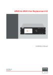
1
2
3
1
USB connection color sensor
2
RS232 connection from display to PC
3
DVI connection from display to PC
Figure 4: Calibration system connection
•
Plug the sensor (delivered together with the DCMS software) in one of the
USB connections of your PC. See also ‘Optical sensor connection’ paragraph.
The USB color sensor measures color and luminance.
•
Connect the display to be calibrated to the PC by using the correct RS232
cable. The RS232 is used to control the display and to upload the calibration
parameters. The RS232 can also be used to set RGB test patterns in stead of
DVI or when no DVI connection to the monitor is available.
•
Connect a DVI cable (not delivered) between PC and display to be calibrated.
The DVI connection is used to display color patches.
NOTE:
If the display is already connected to a different DVI source, the serial connection can be used
to control the display’s internal test pattern generator for colored test fields.
In this case, the input source is part of the calibration system and the colored test fields are
generated as computer graphics.
IMPORTANT:
The DVI of the PC must be capable of driving the display at its native resolution with 24 bit
color resolution.
24 __________________________________________________________Barco - DCMS - User Manual
Connecting the components
CAUTION:
Barco displays are connected with a 3-wire, crossed or straight serial cable. DCMS provides 2
serial cables: one 3-wire crossed cable and one 3-wire straight cable. The 3-wire crossed cable
(Z3498894) is to be used for ISIS and MDPW displays; The 3-wire straight cable (K3494481) is
to be used for ADP, NSL-4601 and LC displays.
Barco - DCMS - User Manual _________________________________________________________ 25
Running the DCMS application
6
Running the DCMS application
6.1
User Interface
6.1.1
DCMS User Interface
The DCMS User Interface window has 3 main panels:
1
3
2
1
Connection panel
2
Sensor panel
3
Calibration target panel
Figure 5: DCMS User Interface
26 __________________________________________________________Barco - DCMS - User Manual
Running the DCMS application
6.1.2
Connection panel
The user can select the display type and display communication details in the
Connection Panel. The displays that are supported are the Barco ISIS,
MDPW476, ADP361, NSL-4601 and the LCx4x series displays. The specifics for
each of these displays are described later in this document. Display
communication is done via serial communication. Every serial port of the host is
listed in the ‘COM port’ combo box. The Baud rate of the selected serial port can
be chosen in the ‘Baud rate’ combo box. In the ‘Monitor ID’ spinner, the user can
select the serial communication ID of the monitor. This is useful for displays that
are chained after each other on the same serial port. How to change the Monitor
ID of your display is described in the User Manual of the display.
Once the correct display type and communication details are set, press ‘Connect’
to start communication with the display. On successful communication with the
display, the button will change text to ‘Disconnect’ and the Status field will color
green and show ‘CONNECTED’. Press the button that is now labeled ‘Disconnect’
to stop communication with the selected monitor. The Status field will color red
again and show ‘DISCONNECTED’. Changing display type or communication
details is not possible as long as the connection is active.
6.1.3
Sensor panel
Calibration of the sensor
The Sensor Panel contains the USB sensor related functions. Press the ‘Calibrate’
button to open a connection to the sensor and calibrate it. After pressing the
‘Calibrate’ button, a dialog window will appear that explains the actions to be
taken: Connect the USB color sensor to the PC and Place the USB color sensor
on a dark surface or in the sensor pod and press 'Calibrate Sensor'. Perform this
step in dark room conditions for optimal results.
Figure 6: Sensor Calibration Dialog
Barco - DCMS - User Manual _________________________________________________________ 27
Running the DCMS application
Press the ‘Calibrate Sensor’ button to start calibration. This process takes about
10 seconds to complete.
After successful connection and calibration of the sensor, the progress bar of the
Sensor Calibration dialog will color green and show ‘Calibration passed’. The
Status field of the Sensor panel will color green and show ‘CALIBRATED’. If
connection or calibration failed, both progress bar and Status field will color red
and show ‘CALIBRATION FAILED’ and ‘NOT CALIBRATED’. The calibration will fail
if the sensor is not plugged in or if the sensor is placed on a bright surface.
Press the ‘Close’ button to return to the main application.
IMPORTANT:
For optimal performance of the sensor it is necessary to place the sensor on a black and darkened surface or place the sensor in the sensor pod. An incorrect calibration of the sensor leads
to invalid results. If the sensor is taken from a cold storage room, allow the sensor to acclimatize to the ambient temperature before use.
A recalibration of the sensor is required in the following conditions:
•
the sensor was disconnected
•
the ambient temperature has changed
•
the last calibration of the sensor is more than a few hours old
Single measurement
For various reasons, the user may wish to know the color coordinates and
luminance of a test patch on a display. This function is provided under ‘Single
Measurement’. This button hides a dialog box. Place the sensor on the sample
and press ‘Measure’. When the measurement is done, the progress bar will stop
running and the color coordinates and luminance are shown. Press ‘Close’ to
return to the main application window. The measurement is done in CIE1931xyY
color space.
Figure 7: Single measurement
28 __________________________________________________________Barco - DCMS - User Manual
Running the DCMS application
6.1.4
Calibration target panel
The Calibration Target Panel contains 8 sections. Each of these sections are
listed and described below. Depending on the type of display that is selected,
some of these sections may be disabled. A disabled section means that this
functionality is not supported by the display.
Test patch
The user can select the preferred way of measuring. To acquire calibration
parameters (the ‘Get’ function that is described below) or to calibrate a display,
the DCMS software needs to measure colored test patches. These test patches
can be generated as a colored field in the application itself or use the internal
built-in-test pattern generator that is available in each display.
Select ‘External computer graphics’ to generate the test patches as a colored
field in the application itself. Choose this option if your host is the video source
for the display that you wish to calibrate. Note that the calibration dialog window
will always be on top of all applications to prevent obfuscation of the test
patches by other applications or dialog windows during the calibration.
Figure 8: External test patch
Select ‘Internal display pattern generator’ to let DCMS instruct the display to
generate the test patches. Choose this option if your host is not the video source
for the display that you whish to calibrate. The size of the test patch depends on
the display’s implementation of this function.
Figure 9: Internal test patch
Barco - DCMS - User Manual _________________________________________________________ 29
Running the DCMS application
Note that the input source will not be visible for the duration of the calibration
when the display pattern generator is selected.
White point
The White point of a display is the color of full white. A color display’s white is
the combination of all three primary colors red, green and blue. The proportion
red, green and blue defines the color of white.
Figure 10: Additive colors
The White point can be expressed in Color Temperature (the temperature in
degrees Kelvin at which a heated black-body radiator matches the color of the
light source’s color). A bluish white has a high color temperature (commonly
referred to as cold white) while a reddish white has a low color temperature
(commonly referred to as warm white).
Example of 5000K
Example of 7500K
Figure 11: Color temperature examples
Figure 12: Color temperature scale*
*This picture is licensed under Creative Commons Attribution ShareAlike 2.5
Poland License.
30 __________________________________________________________Barco - DCMS - User Manual
Running the DCMS application
Select the ‘Color temperature’ radio button to define the white point in color
temperature and use the slider to set the desired color temperature between
3200 and 9900K. Note that daylight is typically 6500K. The selected color
temperature can be read in the text field on right of the slider.
For expert use, you can also give the desired white point in CIE1931xyY
coordinates. Figure below shows the CIE1931xyY color space. In this chart, all
color temperatures between 2000 and 10000K are also shown.
Figure 13: CIE1931xyY color space
Select the ‘CIE1931xyY’ radio button if you wish to set the desired white point in
CIE1931xyY color coordinates in the two text fields below, labeled ‘x’ and ‘y’. For
your convenience, the color temperature slider may still be used to set an initial
x and y value to start from. In the text field on the right, labeled ‘Tc(K)’ you can
read the correlated color temperature. Below this text field, a second text field
labeled ‘u’v’’ shows how far the entered x and y coordinates deviate from the
Planckian locus (this is the path that a black-body follows as it is heated). This
deviation is expressed in distance in the CIE1976UCS color space (which is a
color space that is proportional to human perception of color differences). Both
these text fields will color red if no correlated color temperature can be
calculated for the entered x and y coordinates.
Mid gray
For some applications (like color matching of displays) the mid* gray point can
also be defined. This setting is intended for expert use. The desired color
coordinates and luminance (in CIE1931xyY) of mid gray can be changed here.
*Mid gray in 3x8 bit RGB color space is defined here as (128, 128, 128)
Barco - DCMS - User Manual _________________________________________________________ 31
Running the DCMS application
The three input text fields ‘x’, ‘y’ and ‘Y’ are disabled as long as the check box
‘Follow white point and gamma’ is selected. This means that changing white
point, gamma or brightness settings will influence the mid gray point. The color
coordinates will match those of the white point and the luminance is calculated
from the gamma and the brightness.
Uncheck the ‘Follow white point and gamma’ will allow you to set the desired mid
grey point if this should differ from the white point.
Figure 14: Match of white and mid gray color
Figure 15: Mismatch of white and gray color
Gamma
Human vision has a non-linear perception of changes in luminance (light
intensity). This non-linearity can be characterized by a power-law expression.
This power-law is used in display technologies to map the number of possible
gradations in luminance to a more perceptually uniform space. The Greek letter
gamma is the power in this power-law expression. Typical gamma values for
displays range from 1.8 to 2.8. The pictures below illustrate changes in gamma.
Figure 16: The gamma power-law
32 __________________________________________________________Barco - DCMS - User Manual
Running the DCMS application
Figure 17: Gamma 4
Figure 18: Gamma 2
Figure 19: Gamma 1
The gamma slider can be used to set the desired gamma of the display. This
value can also be seen in the text field on the right of the gamma slider. The
luminance of the gray point changes by definition when the gamma changes.
Note that the gamma slider is disabled when the mid grey point is defined by the
user (when the ‘Follow white point and gamma’ is unchecked). The user defined
luminance of the mid grey point now defines by definition also the gamma. The
text field of the gamma value will color red if the resulting gamma is out of the
slider’s range. So, the mid grey luminance is in function of the desired gamma or
the gamma is in function of the desired mid grey luminance.
Brightness
The brightness of a display is the maximum luminance of full white. The slider
allows the user to set the desired brightness. Values between 25 and 250 cd/m2
in steps of 5 can be chosen for almost all displays exept for NSL-4601 displays,
where the brightness can be set from 100 to maximum 650 cd/m² in steps of
10. The text field on the right shows the desired brightness. If the desired
brightness cannot be reached because of the limitations of the display, the
calibration routine will continue with the closest match but will report a failed
calibration at the end of the routine.
Status field
The Status field has 4 possible states:
No display has been connected
Unknown Calibration History
Display
CALIBRATION SUCCESSFUL
Display was calibrated successfully
CALIBRATION FAILED
Display calibration failed, target settings were
out of range or calibration was interrupted
Barco - DCMS - User Manual _________________________________________________________ 33
Running the DCMS application
Get, Load, Save and Reset
Besides using the controls above, the user has the option to ‘Load’ a previously
defined set of parameters from file or ‘Save’ the current set to file.
Use the ‘Get’ function to acquire these settings by measurement. This is useful
for display matching purposes. How to match displays is explained in the section
“Using DCMS, Match displays” further in this document.
Use the ‘Reset’ function to perform a reset of all calibration parameters (gamma,
brightness,…) to their factory default values. Since not all prameters are
supported by every display, unsupported parameters will be skipped.
Calibrate
Once the parameters are set to the desired values, press the ‘Calibrate now...’
button to start the calibration routine. See the section on “Using DCMS, Calibrate
a display” for a complete explanation of the functionality behind this button.
Figure 20: Barco DCMS – Calibration window
34 __________________________________________________________Barco - DCMS - User Manual
Running the DCMS application
6.2
Using DCMS
6.2.1
Proper use and general remarks
6.2.2
•
Store the sensor at the same ambient temperature as the display, facing
down in the sensor pod.
•
When placing the sensor on the test patch, lead the cable over the top of the
display. Use the contra weight on the USB cable of the sensor to balance the
weight of the sensor. This prevents damage to the sensor if the suction cup
would release its grip.
•
If the suction cup does not hold, slightly moisten the suction cup.
•
Allow displays a warm up time of a few hours to stabilize before calibrating
them.
Calibrate a display
In this section we will calibrate a display to a set of target values. Calibrating
several displays is just a matter of repeating these steps for each of the displays
that need calibration.
Figure 21: Display calibration
Step 1: Connection and startup
•
Physically connect the display via serial connection to the host. Refer to the
documentation of the display for pin-out of the serial port.
•
Connect the USB sensor to the host.
•
Start the DCMS application.
Step 2: Calibration and serial communication
•
Select the display type, serial port number, baud rate and monitor ID
(Default monitor ID is 1). Press ‘Connect’ and verify in the connection status
field that the connection to the display says ‘CONNECTED’.
•
Start the sensor calibration routine by pressing ‘Calibrate…’. Follow the
instructions of the calibration dialog as mentioned in the “User Interface,
Barco - DCMS - User Manual _________________________________________________________ 35
Running the DCMS application
Calibration target panel” paragraph above. Verify that the sensor status field
states ‘CALIBRATED’.
Step 3: Calibration target
•
Select the type of test patches to be used. Select ‘External computer graphics’ if the host is the input source of the display and you want the want the
test patterns to be created in the calibration dialog. Select ‘Internal display
pattern generator’ when the display has an input source different from the
host. See the “User Interface, Sensor panel” paragraph for more details on
the selection of the test patch.
•
Set the desired white point, mid gray, gamma and brightness by manually
changing the settings or load a previous set from file. See the “Sensor
panel” paragraph for details on calibration target settings and the paragraph
“Display connection and calibration” for specifics of the display.
Step 4: The calibration routine
•
Press ‘Calibrate now…’ to open the calibration dialog.
•
Follow the instructions as given in the calibration dialog and press ‘Start’ to
start the calibration routine.
•
During the calibration routine, the user may interrupt at any time by pressing the ‘Close’ button to return to the main application.
NOTE:
Note that the display will not return to a previously known state but will leave the display in the
state that it was at the time of pressing the ‘Close’ button.
•
The user is informed of each step of the calibration in the text area of the
calibration dialog.
•
During calibration the progress bar is colored blue.
•
When the calibration is finished, the progress bar will display if the calibration was successful or not and color green when successful, red if failed. The
same message will appear in the calibration status field of the main application window. As soon as this message appears, you may close this dialog
box.
•
If the dialog box is not closed after calibration, a verification process will
start. This process measures all gray levels in steps of 16 from 0 to 255 and
displays the measured results together with the desired values. See section
6 for details on the verification table.
•
After the verification routine, the test patch will show a green color if the calibration was successful or red if it failed. Text in the text area of the calibration window can be copied and pasted into your favorite text editor and
saved to file.
•
Press ‘Close’ to return to the main application. Pressing ‘Start’ will redo the
calibration routine all over again. If ‘Internal display pattern generator’ was
selected, the display will switch back to the previously selected input when
the calibration dialog is closed.
36 __________________________________________________________Barco - DCMS - User Manual
Running the DCMS application
6.2.3
Match displays
In this section we will calibrate a display (target display) to match another
display (reference display). The displays do not need to be of the same type.
Reference display
Target display
Figure 22: Matching of displays
Step 1: Connection and startup
•
Physically connect the reference display via serial connection to the host.
Refer to the documentation of the display for pin-out of the serial port.
•
Connect the USB sensor to the host.
•
Start the DCMS application.
Step 2: Calibration and the reference display
•
Select the display type, serial port number, baud rate and monitor ID
(Default monitor ID is 1). Press ‘Connect’ and verify in the connection status
field that the connection to the display says ‘CONNECTED’.
•
Start the sensor calibration routine by pressing ‘Calibrate…’. Follow the
instructions of the calibration dialog as mentioned in the ‘Sensor Panel’ section described above. Verify that the sensor status field says ‘CALIBRATED’.
Step 3: Set parameters
•
Select the type of test patches to be used. Select ‘External computer graphics’ if the host is the input source of the display and you want the want the
test patterns to be created in the calibration dialog. Select ‘Internal display
pattern generator’ if the display has an input source different from the host.
Barco - DCMS - User Manual _________________________________________________________ 37
Running the DCMS application
See the “User Interface, Sensor panel” paragraph above for more details on
the selection of the test patch.
•
There is no need to set other parameters as it is the objective of this process
to acquire these from the reference display.
Step 4: The acquisition
•
Press ‘Get…’ to open the acquisition dialog.
•
Follow the instructions as given in the calibration dialog and press ‘Start’ to
start the acquisition routine.
•
During the acquisition routine, the user may interrupt at any time by pressing the ‘Close’ button to return to the main application.
•
The user is informed of each step of the acquisition in the text area of the
acquisition dialog.
•
During acquisition the progress bar is colored blue.
•
When the acquisition in finished, the progress bar will display if the acquisition was successful or not and color green when successful, red if failed. As
soon as this message appears, you may close this dialog box.
•
After the routine, the test patch will show a green color if the routine was
successful or red if it failed. Text in the text area of the calibration window
can be copied and pasted into your favorite text editor and saved to file.
White point, mid gray, gamma* and brightness are automatically copied to
the main application window.
•
Press ‘Close’ to return to the main application. Pressing ‘Start’ will redo the
routine all over again. If ‘Internal display pattern generator’ was selected,
the display will switch back to the previously selected input when the acquisition dialog is closed.
* Gamma and mid gray luminance may differ slightly if recalculated as gamma is
calculated as a best fit from 8 gray levels between 0 and 255.
Step 5: The target display
•
Press ‘Disconnect’ to stop communication with the reference display.
•
Physically connect the target display via serial connection to the host. Refer
to the documentation of the display for the serial port pinning.
•
Select the display type, serial port number, baud rate and monitor ID
(Default monitor ID is 1) of the target display. Press ‘Connect’ and verify in
the connection status field that the connection to the display says ‘CONNECTED’.
Step 6: Set parameters
•
Select the type of test patches to be used. Select ‘External computer graphics’ if the host is the input source of the display and you want the want the
test patterns to be created in the calibration dialog. Select ‘Internal display
pattern generator’ when the display has an input source different from the
host. See the “User Interface, Calibration Target Panel” paragraph above for
more details on the selection of the test patch.
•
All calibration target values are automatically set during the acquisition routine on the reference monitor. If needed, changes can be still be made here.
38 __________________________________________________________Barco - DCMS - User Manual
Running the DCMS application
Step 7: The calibration routine
•
Press ‘Calibrate now…’ to open the calibration dialog.
•
Follow the instructions as given in the calibration dialog and press ‘Start’ to
start the calibration routine.
•
During the calibration routine, the user may interrupt at any time by pressing the ‘Close’ button to return to the main application.
NOTE:
Note that the display will not return to a previously known state but will leave the display in the
state that it was at the time of pressing the ‘Close’ button.
6.2.4
•
The user is informed of each step of the calibration in the text area of the
calibration dialog.
•
During calibration the progress bar is colored blue.
•
When the calibration in finished, the progress bar will display if the calibration was successful or not and color green when successful, red if failed. The
same message will appear in the calibration status field of the main application window. As soon as this message appears, you may close this dialog
box.
•
If the dialog box is not closed after calibration, a verification process will
start. This process measures all gray levels in steps of 16 from 0 to 255 and
displays the measured results together with the desired values. See section
6 for details on the verification table.
•
After the verification routine, the test patch will show a green color if the calibration was successful or red if it failed. Text in the text area of the calibration window can be copied and pasted into your favorite text editor and
saved to file.
•
Press ‘Close’ to return to the main application. Pressing ‘Start’ will redo the
calibration routine all over again. If ‘Internal display pattern generator’ was
selected, the display will switch back to the previously selected input when
the calibration dialog is closed.
Single measurement
The single measurement function allows the user to use DCMS as a simple
luminance and chromaticity meter. Note that a serial connection to a display is
not required for this function.
Step 1: Connection and startup
•
Connect the USB sensor to the host.
•
Start the DCMS application.
Step 2: Calibration
•
Start the sensor calibration routine by pressing ‘Calibrate…’. Follow the
instructions of the calibration dialog as mentioned in the ‘Sensor Panel’ section above. Verify that the sensor status field says ‘CALIBRATED’.
Barco - DCMS - User Manual _________________________________________________________ 39
Running the DCMS application
Step 3: Measurement
•
Press the ‘Single measurement’ button to open the measurement dialog.
•
Place the sensor on a color patch on the display to be measured and press
‘Measure’. The luminance and xy color coordinates will appear in the text
field as soon as the measurement is done. Press ‘Close’ to return to the main
window or press ‘Measure’ for another measurement.
40 __________________________________________________________Barco - DCMS - User Manual
Display connection and calibration options
7
Display connection and calibration
options
7.1
ADP361
Connection
The Barco ADP361 can be connected to the host by means of a 3-wire straight
(Rx-Rx, Tx-Tx, GND-GND) male-female cable. This cable is provided in the DCMS
package.
Calibration options
Figure 23: DCMS with ADP361
The ADP display supports all the functionality of DCMS. However, for calibration
of the gray levels, only the mid gray (RGB 128, 128, 128) is calibrated. The color
of the mid gray point can be set to a value different from the white point as this
display is typically used in combination with the Barco MDP471 which has a mid
gray point that is slightly different from its white point.
Barco - DCMS - User Manual _________________________________________________________ 41
Display connection and calibration options
7.2
LCx-4x
Connection
The Barco LCx-4x series displays (LCN/LCS-42/47) can be connected to the host
by means of a 3-wire straight (Rx-Rx, Tx-Tx, GND-GND) male-female cable. This
cable is provided in the DCMS package.
Calibration options
Figure 24: DCMS with LCx-4x
The LCx-4x display supports all the functionality of DCMS. Note that the option
to set the mid gray color is disabled. Mid gray calibration is not needed as a full
gray tracking is done. Gray tracking is done with the help of high precision lookup tables embedded in the display and programmed by DCMS.
Note that a valid input source is required on this type of display for the internal
test pattern generator to work as the generator uses the applied input timing for
the generation of the test patches.
42 __________________________________________________________Barco - DCMS - User Manual
Display connection and calibration options
7.3
MDP471 (ISIS)
Connection
The Barco MDP471 (code name ISIS) display can be connected to the host by
means of a 3-wire crossed male-female cable (Rx-Tx, Tx-Rx, GND-GND). This
cable is provided in the DCMS package.
Calibration options
Figure 25: DCMS with MDP471
The ISIS display currently only supports the calibration of luminance. All other
controls are disabled. In typical use, this display is often the reference display
for the matching functionality of DCMS in combination with the Barco ADP361.
Barco - DCMS - User Manual _________________________________________________________ 43
Display connection and calibration options
After calibration following dialog box pops up:
Here you can choose whether the calibration value should be stored or not.
Pressing the Cal pushbutton on the MDP471 control unit will take the stored
brightness value and set the brightness of your display to that value.
NOTE:
This can only be done when no OSD menu is active or when OSD level 1 is active. More info
about the OSD and its levels can be found in the user manual of the unit.
44 __________________________________________________________Barco - DCMS - User Manual
Display connection and calibration options
7.4
MDPW476
Connection
The Barco MDPW476 display can be connected to the host by means of a 3-wire
crossed male-female cable (Rx-Tx, Tx-Rx, GND-GND). This cable is provided in
the DCMS package.
Calibration options
Figure 26: DCMS with MDPW476
The MDPW476 display supports all the functionality of DCMS. Mid gray
calibration is not needed as a full gray tracking is done. Gray tracking is done
with the help of high precision look-up tables (LUTs) embedded in the display
and programmed by DCMS. The MDPW is able to store up to 4 color calibration
settings that are also selectable via OSD menu (on-screen-display menu).
Before the calibration dialog is displayed, an MDPW specifics dialog is displayed
first. The progress bar below is colored blue while DCMS is retrieving this
information from the display and will color green as soon as this information is
available.
Barco - DCMS - User Manual _________________________________________________________ 45
Display connection and calibration options
Figure 27: MDPW LUT selection
The user can now select which of the 3 look-up-table slots the user wishes to
overwrite with the new calibration (slot 0 is reserved for a native 1-to-1 LUT).
Select one of the 3 available slots. Each slot can also be given a name for easy
identification of the calibration settings that is stored in the slots. Do not use
special characters for the naming of these slots.
A second MDPW specific function is the ‘Extended dimming’. In case of low
ambient light, the user may wish to dim the maximum luminance beyond the
maximum dimming point of the display’s backlight system. This function uses
the high-precision look-up-tables to dim the display beyond this point.
Press ‘Cancel’ to return to the main window application or ‘Continue’ to advance
to the calibration dialog.
46 __________________________________________________________Barco - DCMS - User Manual
Display connection and calibration options
7.5
NSL-4601
Connection
The Barco NSL-4601 displays can be connected to the host by means of a 3-wire
straight (Rx-Rx, Tx-Tx, GND-GND) male-female cable. This cable is provided in
the DCMS package.
For a single display calibration:
•
Connect the RS cable (delivered with DCMS) and the signal cable (RGB/DVI)
to the NSL-4601 display. Disconnect all other cables (e.g. DVI out).
•
Make sure the display is set as master display.
For the calibration of a display in a wall structure:
•
Connect the RS cable (delivered with DCMS) to the master display
•
Make sure that you can display the BCM dialog on the to be calibrated display in the wall.
See BCM manual for more detailed information about the BCM software
package.
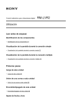
Calibration options
Figure 28: DCMS with NSL-4601
The NSL-4601 displays support all the functionality of DCMS. Note that the
option to set the mid gray color is disabled. Mid gray calibration is not needed as
a full gray tracking is done. Gray tracking is done with the help of high precision
look-up tables embedded in the display and programmed by DCMS.
Barco - DCMS - User Manual _________________________________________________________ 47
Display connection and calibration options
The monitor ID is the address of a monitor. The monitor address is a double (x,
y) where x represents the horizontal position (column) and y the vertical
position (row) of the monitor in the wall. The top left monitor (seen from front)
has the address (0,0):Numbering starts with zero and goes from left to right and
from top to bottom. The address is set in binary code via two 4-dip switches at
rthe rear sid of the monitor, one for x and one for y. The following table shows
how the dip-switch settings are mapped to monitor ID’s:
Vertical Dip Switches
0
1
2
3
4
5
6
7
8
9
10
11
12
13
14
15
0
0
16
32
48
64
80
96
112
128
144
160
176
192
208
224
240
1
1
17
33
49
65
81
97
113
129
145
161
177
193
209
225
241
2
2
18
34
50
66
82
98
114
130
146
162
178
194
210
226
242
3
3
19
35
51
67
83
99
115
131
147
163
179
195
211
227
243
4
4
20
36
52
68
84
100
116
132
148
164
180
196
212
228
244
Horizontal Dip Switches
5
6
7
8
9 10
5
6
7
8
9 10
21 22 23 24 25 26
37 38 39 40 41 42
53 54 55 56 57 58
69 70 71 72 73 74
85 86 87 88 89 90
101 102 103 104 105 106
117 118 119 120 121 122
133 134 135 136 137 138
149 150 151 152 153 154
165 166 167 168 169 170
181 182 183 184 185 186
197 198 199 200 201 202
213 214 215 216 217 218
229 230 231 232 233 234
245 246 247 248 249 250
11
11
27
43
59
75
91
107
123
139
155
171
187
203
219
235
251
12
12
28
44
60
76
92
108
124
140
156
172
188
204
220
236
252
13
13
29
45
61
77
93
109
125
141
157
173
189
205
221
237
253
14
14
30
46
62
78
94
110
126
142
158
174
190
206
222
238
254
15
15
31
47
63
79
95
111
127
143
159
175
191
207
223
239
255
Figure 29: Monitor ID mapping table
Note that a valid input source is required on this type of display for the internal
test pattern generator to work as the generator, as it uses the applied input
timing for the generation of the test patches.
Once the calibration is completed, a dialog box appears to ask if you want to
continue. When pressing continue, the calibration data will be written to the
flash. When finished, the display will be automatically restart.
Figure 30: Calibration NSL-4601 completed
48 __________________________________________________________Barco - DCMS - User Manual
Display connection and calibration options
Color versus brightness
NOTE:
Note that reducing the color temperature reduces the overall achievable brightness.
The table below provides an indication of the relative brightness compared to the
brightness at native color temperature, which is 10000K.
Color temperature
Brightness (relative)
3200K
between 50% and 55%
5000K
between 70% and 75%
5500K
between 75% and 80%
6500K
approx. 85%
7500K
between 90% and 95%
9300K
approx. 95%
10000K
100% as this is the native color temperature
Table 1: Color temperature versus brightness
Barco - DCMS - User Manual _________________________________________________________ 49
Calibration
8
Calibration
Calibration is done in 3 major steps:
START
Reset
Measurement
native
characteristics
Iterative calibration
1
2
3
STOP
1
Calibration reset
2
Measurement of native characteristics
3
Interative calibration
Figure 31: Calibration steps flowchart
Each of these steps is explained in detail in the following subparagraphs.
Calibration reset
The first step in the calibration process is resetting all parameters that are to be
calibrated or may influence the calibration. Not all parameters are supported by
every display. Unsupported parameters are skipped.
Resetting these parameters to their default, neutral or disabled value allows us
to measure the native characteristics of the display in the next step.
Native characteristics
In the second step of the calibration process, the native characteristics are
measured and calculated. First, the black is measured. This will later be used in
the algorithms to compensate for black. In this context, black is not the total
absence of light but is the darkest possible luminance that can be achieved.
Since this black has a luminance that is not equal to zero, it also has a color and
therefore needs to be reckoned with when calibrating the display.
Next, we loop over the three primary colors red, green and blue. For each of
these colors, we measure luminance, color and native gamma.
50 __________________________________________________________Barco - DCMS - User Manual
Calibration
Finally, we measure the luminance and color of the maximum native white. This
is our starting point from where we calibrate to the required white point.
Calibration
The third step in the calibration process is the actual calibration. Everything is
done by gray tracking calibration as full white can be seen as just a special kind
of gray. This gray tracking is done for a reduced set of gray levels to reduce
calibration time without compromising the end result.
Barco - DCMS - User Manual _________________________________________________________ 51
Verification
9
Verification
The verification table below lists an example output of a verification table. After
the calibration process, the user can start a verification of the results by pressing
the ‘Start verification’ button in the calibration dialog. The layout of this table is
always the same but the content may depend on the type of display that is
calibrated. The example below is taken after calibration of a Barco MDPW476.
Table 2: Verification table
Verification is done by measuring the color and luminance of a set of gray levels,
including white. The measured results are compared to the calculated theoretical
values and printed on screen.
52 __________________________________________________________Barco - DCMS - User Manual
Verification
The report shows:
Table 3: Verification table explanation
Barco - DCMS - User Manual _________________________________________________________ 53
The log file
10
The log file
Each time the DCMS application is started, a new log file is created. This file is
named ‘dcmsxxx.log’ where xxx is the timestamp of creation. The log file
contains all text that is displayed in the instructions panel of the ‘calibration
dialog’ and ‘get calibration dialog’. It also lists the measurement results of the
verification routine and single measurements. The file is stored in the installation
folder of DCMS.
54 __________________________________________________________Barco - DCMS - User Manual
List of abbreviations
11
List of abbreviations
A
ADP
Auxiliary Display Panel
ALC
Ambient Light Controller
B
BCM
Barco wall Control Manager
BIT
Built In Test
Bkl
Backlight
BLOS
Backlight OpticaL Stabilisation
Bri
Brightness
C
Cal
Calibrate
CCFL
Cold Cathode Fluorescent Lamp
cd
candela
COMM
Communication
Conn.
Connector
CRT
Cathode Ray Tube
D
DCMS
Display Consistency Management Software
Diff
Differential
DVI
Digital Video Interface
L
LCD
Liquid Crystal Display
LUT
Look-Up Table
M
MDPW
Main Display Panel Wide screen
MISC
Miscellaneous (keypad)
ms
Millisecond
N
N/A
Not Applicable
Nr
Number
NSL
Near Seamless LCD
O
Opt
Optical
OSD
On Screen Display
P
PWR
Power
R
RGB
Red Green Blue
RX
Receiver
S
Barco - DCMS - User Manual _________________________________________________________ 55
List of abbreviations
SMPTE
Society of Motion Picture and Television Engineers
STD
Standard
SVGA
Super Video Graphic Array
SW
Software
SXGA
Super extended Graphics Array
S/N
Serial Number
T
Temp
Temperature
TX
Transmitter
U
UMAN
User Manual
USB
Universal Serial Bus
UXGA
Ultra eXtended Graphic Array
V
V
Volt
VGA
Video Graphic Array
VHDL
Is the VHSIC Hardware Description Language
W
WUXGA
Widescreen Ultra eXtended Graphics Array
X
XGA
EXtended Graphic Array
Y
Y
Luminance
56 __________________________________________________________Barco - DCMS - User Manual
Appendix A: Open Source Software
12
Appendix A: Open Source Software
DCMS copyright
DCMS is copyrighted by Barco nv with exception of the RXTXComm library.
RXTXComm is open source software, licensed under the ‘RXTX extension to
LGPL’. The full RXTXComm and LGPL license can be found on the DCMS CD-ROM.
RXTX extension to LGPL
RXTX License v 2.1 - LGPL v 2.1 + Linking Over Controlled Interface. RXTX is a
native interface to serial ports in java. Copyright 1997-2007 by Trent Jarvi
[email protected] and others who actually wrote it. See individual source files for
more information.
A copy of the LGPL v 2.1 may be found at http://www.gnu.org/licenses/lgpl.txt
on March 4th 2007. A copy is here for your convenience.
This library is free software; you can redistribute it and/or modify it under the
terms of the GNU Lesser General Public License as published by the Free
Software Foundation; either version 2.1 of the License, or (at your option) any
later version.
This library is distributed in the hope that it will be useful, but WITHOUT ANY
WARRANTY; without even the implied warranty of MERCHANTABILITY or
FITNESS FOR A PARTICULAR PURPOSE. See the GNU Lesser General Public
License for more details.
An executable that contains no derivative of any portion of RXTX, but is designed
to work with RXTX by being dynamically linked with it, is considered a "work that
uses the Library" subject to the terms and conditions of the GNU Lesser General
Public License.
The following has been added to the RXTX License to remove any confusion
about linking to RXTX. We want to allow in part what section 5, paragraph 2 of
the LGPL does not permit in the special case of linking over a controlled
interface. The intent is to add a Java Specification Request or standards body
defined interface in the future as another exception but one is not currently
available.
http://www.fsf.org/licenses/gpl-faq.html#LinkingOverControlledInterface
As a special exception, the copyright holders of RXTX give you permission to link
RXTX with independent modules that communicate with RXTX solely through the
Sun Microsytems CommAPI interface version 2, regardless of the license terms
of these independent modules, and to copy and distribute the resulting
combined work under terms of your choice, provided that every copy of the
combined work is accompanied by a complete copy of the source code of RXTX
(the version of RXTX used to produce the combined work), being distributed
under the terms of the GNU Lesser General Public License plus this exception.
An independent module is a module which is not derived from or based on RXTX.
Note that people who make modified versions of RXTX are not obligated to grant
this special exception for their modified versions; it is their choice whether to do
so. The GNU Lesser General Public License gives permission to release a
modified version without this exception; this exception also makes it possible to
release a modified version which carries forward this exception.
You should have received a copy of the GNU Lesser General Public License along
with this library; if not, write to the Free Foundation, Inc., 59 Temple Place, Suite
330, Boston, MA 02111-1307 USA. All trademarks belong to their respective
owners.
Barco - DCMS - User Manual _________________________________________________________ 57
Appendix B: Specifcations
13
Appendix B: Specifcations
13.1
Specifications of the USB sensor
•
Connection type: USB
•
Power supply: through USB.
•
() ( )
Accuracy: y λ = V λ
•
Maximum deviation from reference sensor (Minolta CA 210) on reference
color and grayscale LCD displays:
3
3
3
3
3
•
Y
x
y
x
y
≤
≤
≤
≤
≤
5% from 0.2 to 1000 cd/m2 (typical)
0.005 from 1 to 1000 cd/m2 (typical)
0.005 from 1 to 1000 cd/m2 (typical)
0.01 from 0.2 to 1 cd/m2 (typical)
0.01 from 0.2 to 1 cd/m2 (typical)
Repeatability over 5 measurements:
Y:
3
3
3
3
x, y :
3
3
13.2
∆
∆
∆
∆
∆
0.01 cd/m2 in the range of 0.2 to 1 cd/m2 (typical)
0.05 cd/m2 in the range of 1 cd/m2 to 10 cd/m2 (typical)
0.1 cd/m2 in the range of 10 cd/m2 to 100 cd/m2 (typical)
1 cd/m2 in the range of 100 cd/m2 to 1000 cd/m2 (typical)
0.005 in the range of 0.2 cd/m2 to 0.5 cd/m2 (typical)
0.003 in the range of 0.50 cd/m2 to 1000 cd/m2 (typical)
DCMS specifications
For a typical target of 6500 K, gamma 2.35 and luminance 150 cd/m2, the user
may expect an accuracy of
for gray levels down to 20% drive level.
These values are not binding as results may vary depending specified targets,
display and display type.
58 __________________________________________________________Barco - DCMS - User Manual
Table of contents
14
Table of contents
1 About .............................................................................................. 3
1.1 Contents of the user manual............................................................... 3
1.2 Change record .................................................................................. 3
1.3 Notation convention .......................................................................... 4
2 Important notice ............................................................................... 5
2.1
2.2
2.3
2.4
2.5
2.6
Commercial In Confidence..................................................................
Copyright.........................................................................................
Open Source Software .......................................................................
Embedded pictures............................................................................
Product safety notice .........................................................................
Software License Terms .....................................................................
5
5
5
5
5
6
3 About DCMS ................................................................................... 10
3.1 What is DCMS? ............................................................................... 10
3.2 Why using DCMS? ........................................................................... 10
3.3 Key components ............................................................................. 11
3.3.1 Calibration system............................................................................ 11
3.3.2 Display ........................................................................................... 12
3.3.3 Sensor ............................................................................................ 12
3.4 Package content ............................................................................. 13
4 Installing DCMS .............................................................................. 14
4.1
4.2
4.3
4.4
System requirements ......................................................................
Before installing DCMS.....................................................................
Installing DCMS ..............................................................................
Uninstalling DCMS ...........................................................................
14
14
14
19
5 Connecting the components.............................................................. 21
5.1 Optical sensor connection................................................................. 21
5.2 Calibration system connection........................................................... 24
6 Running the DCMS application .......................................................... 26
6.1 User Interface ................................................................................ 26
6.1.1
6.1.2
6.1.3
6.1.4
DCMS User Interface ........................................................................ 26
Connection panel.............................................................................. 27
Sensor panel ................................................................................... 27
Calibration target panel..................................................................... 29
6.2.1
6.2.2
6.2.3
6.2.4
Proper use and general remarks ......................................................... 35
Calibrate a display ............................................................................ 35
Match displays ................................................................................. 37
Single measurement ......................................................................... 39
6.2 Using DCMS ................................................................................... 35
7 Display connection and calibration options .......................................... 41
7.1
7.2
7.3
7.4
7.5
ADP361 .........................................................................................
LCx-4x ..........................................................................................
MDP471 (ISIS) ...............................................................................
MDPW476 ......................................................................................
NSL-4601 ......................................................................................
41
42
43
45
47
8 Calibration ..................................................................................... 50
9 Verification..................................................................................... 52
10 The log file ................................................................................... 54
Barco - DCMS - User Manual _________________________________________________________ 59
Table of contents
11 List of abbreviations ...................................................................... 55
12 Appendix A: Open Source Software.................................................. 57
13 Appendix B: Specifcations .............................................................. 58
13.1 Specifications of the USB sensor...................................................... 58
13.2 DCMS specifications....................................................................... 58
14.1
Figure
Figure
Figure
Figure
Figure
Figure
Figure
Figure
Figure
Figure
Figure
Figure
Figure
Figure
Figure
Figure
Figure
Figure
Figure
Figure
Figure
Figure
Figure
Figure
Figure
Figure
Figure
Figure
Figure
Figure
Figure
14.2
List of figures
1: External calibration system ........................................................................ 11
2: The input source as part of the calibration system .......................................... 11
3: Sensor head removal ................................................................................. 21
4: Calibration system connection ..................................................................... 24
5: DCMS User Interface .................................................................................. 26
6: Sensor Calibration Dialog ............................................................................ 27
7: Single measurement .................................................................................. 28
8: External test patch .................................................................................... 29
9: Internal test patch ..................................................................................... 29
10: Additive colors ........................................................................................ 30
11: Color temperature examples ...................................................................... 30
12: Color temperature scale* .......................................................................... 30
13: CIE1931xyY color space ............................................................................ 31
14: Match of white and mid gray color .............................................................. 32
15: Mismatch of white and gray color ............................................................... 32
16: The gamma power-law ............................................................................. 32
17: Gamma 4 .............................................................................................. 33
18: Gamma 2 .............................................................................................. 33
19: Gamma 1 .............................................................................................. 33
20: Barco DCMS – Calibration window .............................................................. 34
21: Display calibration .................................................................................... 35
22: Matching of displays ................................................................................. 37
23: DCMS with ADP361 .................................................................................. 41
24: DCMS with LCx-4x ................................................................................... 42
25: DCMS with MDP471 .................................................................................. 43
26: DCMS with MDPW476 ............................................................................... 45
27: MDPW LUT selection ................................................................................. 46
28: DCMS with NSL-4601 ............................................................................... 47
29: Monitor ID mapping table .......................................................................... 48
30: Calibration NSL-4601 completed ................................................................ 48
31: Calibration steps flowchart ........................................................................ 50
List of tables
Table 1:Color temperature versus brightness .............................................................. 49
Table 2:Verification table .......................................................................................... 52
Table 3:Verification table explanation ......................................................................... 53
60 __________________________________________________________Barco - DCMS - User Manual
Table of contents
End of document
Barco - DCMS - User Manual _________________________________________________________ 61