1
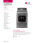
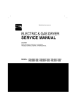
U.S.A. Website: http://us.lgservice.com Canadian Website: http://lg.ca ELECTRIC & GAS DRYER SERVICE MANUAL CAUTION READ THIS MANUAL CAREFULLY IN ORDER TO PROPERLY DIAGNOSE PROBLEMS AND TO SAFELY PROVIDE QUALITY SERVICE ON THESE DRYERS. MODEL : DLEX5101W DLEX5101V DLEX5170W DLEX5170V DLGX5102W DLGX5102V DLGX5171W DLGX5171V OCT. 2009 PRINTED IN KOREA P/No.: MFL62119910 IMPORTANT SAFETY NOTICE ! WARNING ! Toavoid personal injury, disconnect power before servicing this product. If electrical power is required for diagnosis or test purposes, disconnect the power immediately after performing the necessary checks. Toreduce the risk of personal injury, adhere to all industry recommended safety procedures including the use of long sleeved gloves and safety glasses. Failure to follow all of the safety warnings in this manual could result in property damage, personal injury or death. RECONNECT ALL GROUNDING DEVICES WHAT TO DO IF YOU SMELL GAS: Immediately call your gas supplier from a neighbor’s phone. Follow the gas supplier’s instructions carefully. If you cannot reach your gas supplier, call the fire department. Do not try to light a match, or cigarette, or turn on any gas or electrical appliance. Do not touch any electrical switches. Do not use any phone in your building. Clear the room, building or area of all occupants. IMPORTANT 2 CONTENTS 1. SPECIFICATIONS ............................................................................................................... 4 2. FEATURES AND BENEFITS ............................................................................................... 6 3. INSTALLATION INSTRUCTIONS ........................................................................................ 6 4. DRYER CYCLE PROCESS ................................................................................................ 10 5. COMPONENT TESTING INFORMATION ......................................................................... 11 6. MOTOR DIAGRAM AND SCHEMATIC ............................................................................. 14 7. WIRING DIAGRAM ............................................................................................................ 15 8. STEAM FUNCTION ............................................................................................................ 16 8-1. STEAM CYCLE GUIDE ............................................................................................ 16 8-2. TROUBLESHOOTING .............................................................................................. 17 8-3. DISPLAY FAULT/ERROR CODES ............................................................................ 18 9. FLOW SENSOR FUNCTION ............................................................................................. 19 9-1. FLOW SENSOR ....................................................................................................... 19 9-2. INSTALLATION CHECK .......................................................................................... 20 9-3. TROUBLESHOOTING FOR FLOW SENSOR DRYER ............................................ 21 10. DIAGNOSTIC TEST ........................................................................................................ 22 10-1. TEST 1 120 VAC ELECTRICAL SUPPLY ............................................................. 23 10-2. TEST 2 THERMISTOR TEST - MEASURE WITH POWER OFF ......................... 26 10-3. TEST 3 MOTOR TEST ......................................................................................... 27 10-4. TEST 4 MOISTURE SENSOR .............................................................................. 28 10-5. TEST 5 DOOR SWITCH TEST ............................................................................. 29 10-6. TEST 6 HEATER SWITCH TEST - ELECTRIC TYPE .......................................... 30 10-7. TEST 7 GAS VALVE TEST - GAS TYPE .............................................................. 31 10-9. TEST 8 MOTOR ASSEMBLY, DC, PUMP ............................................................ 32 10-10. TEST 9 GENERATOR ASSEMBLY .................................................................... 33 11. CHANGE GAS SETTING (NATURAL GAS, PROPANE GAS) ....................................... 34 12. DISASSEMBLY INSTRUCTIONS .................................................................................... 36 13. EXPLODED VIEW ............................................................................................................ 46 13-1. CONTROL PANEL AND PLATE ASSEMBLY ......................................................... 46 13-2. GUIDE ASSEMBLY ................................................................................................. 47 13-3-1. CABINET AND DOOR ASSEMBLY: ELECTRIC TYPE ....................................... 48 13-3-2. CABINET AND DOOR ASSEMBLY: GAS TYPE ................................................. 49 13-4-1. DRUM AND MOTOR ASSEMBLY: ELECTRIC TYPE ......................................... 50 13-4-2. DRUM AND MOTOR ASSEMBLY: GAS TYPE ................................................... 51 3 1 SPECIFICATIONS Name: Electric and Gas Dryer Power supply: Refer to the rating label on the dryer. Gas: 120 VAC Electric: 240VAC Size: 27 X 28.9 X 45.3 (inch) Dryer capacity: IEC 7.3 cu.ft. Weight: 133.2 (Ibs) Specifications are subject to change by manufacturer. ACCESSORIES Dryer rack (1 each) See page 6 of this manual for usage instruction. 4 Color DLEX5101W DLGX5102W DLEX5101V DLGX5102V DLEX5170W DLGX5171W DLEX5170V DLGX5171V Blue White / Stainless Silver Top Plate Powder coating ITEM Material & Finish Door Trim Power Supply Power Consumption Elec. Gas Spray 120 V / 240 V / 60 Hz (26 A) 120 V / 208 V / 60 Hz (23 A) 120 V / 60 Hz (11.5 A) Motor 250W (4.5A) AC 120V Heater 5400W (22.5A) AC 240V(Electric Model) Lamp 15 W (0.2A) DC 12V Gas Valve 13 W (0.11A) x 2 DC 120V(Gas Model) AG Heater 1100W (9.2A) DC 120V(Steam Model) Pump 2.4W (0.15A) DC 9V(Steam Model) Control Type Electronic Drum Capacity 7.3 cu.ft. Weight (lbs) - Net 133.2 No. of Programs 14 No. of Dry Options 6 No. of Temperature Controls 5 No. of Dry Levels 5 Sound levels 3 Sensor REMARK Moisture Available Electrode sensor Temperature Available Thermistor Reversible Door Available Drum Stainless Steel Dryer Rack Available Child Lock Available Interior Light Available Product (WxDxH) 27 x 28.9 x 45.3 (inch) Packing (WxDxH) 29.8 x 31.3 x 47.24 (inch) 5 2 FEATURES AND BENEFITS 3 INSTALLATION INSTRUCTIONS Dryer Rack Installation Instructions Open the door. Hold the dryer rack with both hands. Put the dryer rack into the drum 6 Check and be sure that the front of the rack is properly seated behind the lint filter. Review the following options to determine the appropriate electrical connection for your home: Option 1: 4-wire connection with a Power supply cord. • If your local codes or ordinances do not allow the use of a 3 wire connection, or you are installing your dryer in a mobile home, you must use a 4wire connection. 4-wire receptacle (NEMA type14-30R) Use the instructions under option 1 if your home 1" ) type 14-30R). homehas a 4-wire receptacle (NEMA cm (2.5 3V2" ) m (8.9 c 3-wire receptacle (NEMA type10-30R) Use the instructions under option 2 or 3 if your home has a 3-wire receptacle (NEMA type 10-30R). Use option 2 if local codes and ordinances permit the connection of a chassis ground to the neutral connector. If this is not permitted, use option 3. D E F a b C 7 1. Connect the neutral wire (white) of the power cord to the center terminal block screw. 2. Connect the red and black wires to the left and right terminal block screws. 3. Connect the ground wire (green) of the power cord to the external ground screw. Remove the neutral ground wire of appliance and connect it to center screw. 4. Make sure that the strain relief screw is tightened and that all terminal block nuts are tight and the power cord is in the right position. Option 2: 3-Wire Connection with a Power Supply Cord lf your local codes or ordinances permit the connection of a frame-grounding conductor to the neutral wire, use these instructions. If your local codes or ordinances do not allow the connection of a frame-grounding conductor to the neutral wire, use the instructions under Section 3: Optional 3-wire connection. 1. Connect the neutral (white or center) wire (B) to the center, silver colored, screw (A) and tighten securely. 2. Connect the other two power cord wires (red and black) to the left and right terminal block screws and tighten securely. 3. Tighten the strain relief screws (C) securely. A B C 8 3-2. Connect Gas Supply Pipe (Gas Dryer ONLY) For further assistance, refer to section on Gas Requirements. 1. Make certain your dryer is equipped for use with the type of gas in your laundry room. Dryer is equipped at the factory for natural gas with a 3/8” N.P.T. gas connection. 3. Connect to gas supply pipe using a new flexible stainless steel connector. 4. Tighten all connections securely. Turn on gas and check all pipe connections (internal & external) for gas leaks with a non-corrosive leak detection fluid. 5. For LP (Liquefied Petroleum) gas connection, refer to section on Gas Requirements. 2. Remove the shipping cap from the gas connection at the rear of the dryer. Make sure you do not damage the pipe thread when removing the cap. 1 2 5 3 4 1 New Stainless Steel Flexible Connector - U s e only if allowed by local codes (Use Design A.G.A. Certified Connector) 2 1 /8 ” N.P.T. Pipe Plug ( for checking inlet gas pressure) 3 Equipment Shut-Off Valve-Installed w i t h i n 6 ’ (1.8 m) of dryer 9 4 Black Iron Pipe Shorter than 20’ (6.1 m) - Use 3/8” pipe Longer than 20’ (6.1m) - Use 1 /2” pipe 3 5 /8” N.P.T. Gas Connection 4 DRYER CYCLE PROCESS Conditions of operation and termination Default Cooling Drying Cycle STEAM FRESHTM STEAM SAINTARYTM Sensor Dry * ANTIBACTERIAL BULKY/ BEDDING HEAVY DUTY Temperature Dry Level HIGH MEDIUM Off 20min Saturation 66 4 151 °F 5min 47 5 113 °F HIGH Off 39min Saturation 68 4 155 °F 5min 47 5 113 °F Very Dry Normal Adjustable Normal Adjustable Normal Adjustable Normal Adjustable Normal Adjustable Normal Adjustable Normal Adjustable Normal Adjustable 70min Saturation 5min 47 5 113 °F 55min Saturation 54min Saturation HIGH MEDIUM HIGH PERM PRESS LOW CASUAL COTTON/ MEDIUM NORMAL DELICATES TOWELS SMALL LOAD SPORTS WEAR Manual Dry ** LOW MEDIUM HIGH HIGH MEDIUM Display time Electro- Temp- Default Temptime Control** sensor Control 36min Saturation 41min Saturation 32min Saturation 55min Saturation 30min Saturation 68 155 60 140 68 155 52 126 60 140 52 126 66 151 68 155 4 °F 4 °F 4 °F 3 5min 5min °F 5min °F 5min 4 3 °F 4 5min °F 5min °F 5min 27min 60 4 Saturation 140 °F 5min 4 SPEED DRY HIGH Off 25min (68 4 Saturation (155 °F) 5min AIR DRY NO HEAT Off 30min Saturation Off 50min Saturation (52 3 5min 126 °F) RACK DRY Wrinkle care LOW EXTRA LOW NO HEATER 5min 47 113 47 113 47 113 47 113 47 113 47 113 47 113 47 113 5 °F Time 3Hr 5 °F 5 °F 5 °F 5 °F 5 °F 5 °F 5 °F 47 5 113 °F (47 5 (113 °F) 3Hr N/A Off Time: 6min Motor On Time: 10sec Load Temperature Control for each cycle Heater * Sensor dry: Dry Level is set by users. ** Manual dry: Temperature control is set by users. Default settings can be adjusted by users. 10 5 ! COMPONENT TESTING INFORMATION CAUTION Component 1. Thermal cut off When checking the Component, be sure to turn the power off, and do voltage discharge sufficiently. Test Procedure Measure resistance of terminal to terminal Open at 284 (140 5°C) • Check Top Marking: N140 2.Hi limit Thermostat (Auto reset) 3.Outlet Thermostat ( Auto reset) If thermal fuse is open must be replace Continuity (250°F Open at 257 (125 5°C) 9°F Resistance value Close at 221 (94 7°C) 9°F Resistance value < 5Ω Measure resistance of terminal to terminal 41°F Resistance value Close at 167 41°F (75 5°C) Same shape as Thermal cut off. Measure resistance of terminal to terminal 5. Door switch Measure resistance of the following terminal Resistance value < 5Ω Resistance value: 80Ω ~ 100Ω 1) Door switch knob: open Terminal: COM - NC(1-3) Terminal: COM - NC (1-2) Resistance value < 1Ω Resistance value 2) Door switch push: push Terminal: COM - NC (1-3) Terminal: COM - NC (1-2) Resistance value Resistance value < 1Ω Measure resistance of the following terminal: COM - NC 1. lever open Resistance value < 1Ω 2. Lever push (close) Resistance value 11 • Heater caseSafety • Electric type ) < 1Ω Measure resistance of terminal to terminal 4. Lamp holder 6. Idler switch Remark Resistance value 41°F Auto reset -31°F (-35°C) Same shape as Outlet Thermostat. Open at 185 (85 5°C) • Check Top Marking: N85 Check result • Heater case Hi limit • Electric type • Blow housing Safety • Electric type 5 Component Test Procedure 7. Heater Check result • Electric type Measure resistance of the following terminal Resistance value: 10Ω Terminal: 1 (COM) - 2 Terminal: 1 (COM) - 3 Terminal: 2 - 3 Resistance value: 10Ω Resistance value: 20Ω Measure resistance of terminal to terminal Temperature condition: 58°F ~ 104°F (10~40°C) 8. Thermistor Resistance value: 10Ω 9. Motor 10. Gas valve Remark • Heater case Hi limit • Electric type • See Page 14 valve 1 Measure resistance of the following terminal Valve 1 terminal Valve 2 terminal Resistance value 2.3k~2.7kΩ • Gas type Resistance value 2.3k~2.7kΩ valve 2 11. Igniter 5318EL3001 Resistance value 50~800 Ω (for 5318EL3001) 40-150 Ω (for MEQ1841001) Measure resistance from terminal to terminal. • Gas type MEQ61841001 12. Frame Detect Measure resistance of termina to terminal Open at 370°F (Maximum) Close at 320°F 12 • Gas type Resistance value Resistance value < 1Ω Component 13. Outlet Thermostat (Auto reset) Test Procedure Check result Remark • Gas type • Gas funnel Measure resistance of terminal to terminal Open at 203 41°F (95 5°C Resistance value Close at 159 41°F (70 5°C) Continuity < 1Ω • Check Top Marking: N95 14. Outlet Thermostatt (Manual reset) • Gas type • Gas funnel Measure resistance of terminal to terminal Open at 230 (110 5°C) 41°F Resistance value Continuity < 1Ω Manual reset • Check Top Marking: N100 13 6 NOTE MOTOR DIAGRAM AND SCHEMATIC When checking Component, be sure to turn Power off, then do voltage discharge sufficiently. ■Contact On / Off by Centrifugal Switch Terminal No Remark Mode Resistance Motor 2 ~ 3Ω Motor STOP Motor RUN ᴾᴬ Heater (Electric Models) ᴾᴬ Gas Valve (Gas Models) 3 ~ 5Ω Motor < 1Ω Heater (Electric Models) < 1Ω Gas Valve (Gas Models) ■.RUN MODE ■ STOP MODE (Motor operates) (When Motor does not operate) Centrifugal switch (Pull Drive forward) Centrifugal switch 14 7 WIRING DIAGRAM CAUTION Label all wires prior to disconnection when servicing controls. Wiring errors can cause improper and dangrous operation. Verify proper operation after servicing. ELECTRIC DRYER WIRING DIAGRAM GAS DRYER WIRING DIAGRAM 15 8 STEAM FUNCTION 8-1. Steam Cycle Guide STEAM STEAMSANITARYTM DEFAULT TIME TEMP. DRY FABRIC CONTROL LEVEL STATE Dry 39 minutes 20 minutes Sports wear Comforter Bedding Children’s clothing Comforter Shirts* Dry O + 10 minutes STEAMFRESHTM REDUCE Only reduce static STATIC + 12 minutes EASY IRON + HEAVY DUTY COTTON/TOWELS REDUCE STATIC NORMAL Follow selected PERM.PRESS + cycle DELICATES EASY IRON TIME DRY FABRIC TYPE MAXIMUM AMOUNT Single (1 each) 3 lbs. Single (1 each) 5 each 8 lbs. (18 Items.) Dry Shirts* Dry Shirts* (5 each) O Wet Follow selected cycle 8 lbs. (18 Items.) O Wet Follow selected cycle Shirts* (5 each) + REDUCE STATIC 45 minutes O Wet Follow selected temp 8 lbs. (18 Items.) + EASY IRON 47 minutes O Wet Follow selected temp Shirts* (5 each) + EASY IRON 27 minutes Wet Sports wear *Shirt: 70% cotton/30% poly blend. Except especially delicate fabrics. IMPORTANT NOTES ABOUT STEAM CYCLES: • The steam feeder must be filled with water up to the MAX line. Otherwise, an error message will be displayed. • If the lint filter or exhaust duct is clogged, the Steam options will not give proper results. • For best results, load articles of similar size and fabric type. Do not overload. • Water only - Do not add any additives or other materials as these will damage your dryer. • Before moving the dryer, make sure the steam feeder is empty. • Best results are obtained with cotton/poly blend fabrics. 16 8-2. Troubleshooting for Steam Dryer PROBLEM POSSIBLE CAUSES SOLUTIONS ADD WATER indicator light is on during the drying cycle • Water supply error. • Check steam feeder drawer: (1) Make sure steam feeder is filled with water to MAX line. (2) Make sure steam feeder is seated properly and drawer is fully closed. (3) Turn the dryer off then restart the Steam cycle. • Do not use distilled water; the water level sensor in steam generator will not work. • Pump not working. Unplug dryer and call for service. Water drips from orifice when Steam Cycle starts. • This is normal. • This is steam condensation. The dripping water will stop after a short time. Steam doesn’t generate but no error code is shown. • Water level error. • Unplug dryer and call for service. Garments still wrinkled after STEAM FRESH™. • Too many or to different types of garments in dryer. • Small loads of 1 to 5 items work best. • Load fewer garments. Load similar-type garments. There are no creases left on garment after STEAM FRESH™. • The function of this cycle • Use an iron to make creases. is to remove wrinkles from fabric. Garments have static after REDUCE STATIC. • This is normal. Garments are too damp or too dry after REDUCE STATIC. • Correct drying options • Select load weight manually before starting not selected. REDUCE STATIC option. Garments are not uniformly damp after EASY IRON. • This is normal. • Depends on the amount or type of garments. Water drips from door during Steam Cycle. • This is normal. • This is steam condensation on door surface. Steam is not visible during Steam Cycle. • This is normal. • Steam vapor is difficult to see when the door is closed. Drum does not turn during Steam Cycle. • This is normal. • The drum is turned off so that the steam vapor remains in the drum. • Depends on individual moisture level in skin. 17 POSSIBLE CAUSES PROBLEM SOLUTIONS Cannot see steam vapor at the beginning of cycle. • This is normal. • Steam is released at different stages of the cycle for each option. The display shows BULKY LOAD. • MORE TIME button pressed. • Pressing the MORE TIME button several times will set the cycle for a large load such as a comforter. Odors remain in clothing after STEAM FRESH™. • STEAM FRESH™ did not remove odor completely. • Fabrics containing strong odors should be washed in a normal cycle. 8-3. Display Fault/Error Codes for Steam Dryer The error codes below will be displayed when attempting to start a drying cycle, or after activating the Diagnostic Test mode. DISPLAY Checking Part Cause Remark Thermistor of blower housing • Thermistor open or shorted • tE1 error is displayed in the drying cycle or test mode. • Replace the steam generator. dE Door SW • Door SW is abnormal. (Only TEST MODE ) • dE error is only displayed in the test mode. PS Wire Connection (Black-White-Red) Wire Connection is wrong. Wire Connection is loose. tE4 Thermistor of steam generator • Steam generator thermistor open or shorted. Steam generator See the 7-9 page. Guidance of the wire connection. For only electric dryer. *PS : Power Supply • tE4 error is only displayed in the test mode. • Replace the steam generator. If water in the steam feeder is not enough this error may be isplayed. Fill the feeder and restart the cycle. tE1 tE2 E5 Water supply pump • Sensors do not detect that steam generator is full within 60 seconds. • When the pump valve is less than • E5 error is only displayed in the 10 in the test mode test mode. • Check the connection between harness wire and connector. • Replace the water supply pump. EE EE PROM Error • EE PROM operation is abnormal. • EE error is only displayed in the test mode. Add Water 18 9 FLOW SENSOR FUNCTION 9-1 Flow sensor This FlowSenseTM function detects the clogging or blocking of ducts. Clogged duct vents or hoses decrease efficiency in drying clothes. Clogged vents can also cause fire. This function alarms you, when to clean the ducts. When the alarm about duct clogging is on display of the panel, your duct vents should be cleaned by yourself or serviceman. Flow Sensor Function 19 9-2 Installation check This feature allows you to quickly verify that the exhaust system is adequate for the normal function of the dryer. The check takes only two minutes. The results of the check are displayed in the FlowSense display window as shown below (Fig. 1). The dryer must be at room temperature for this test to be reliable. To perform this test, start the machine in standby mode (power off). Press and hold both the DAMP DRY BEEP and the TEMP . CONTROL buttons together while turning on the dryer with the POWER button i.e. Press together the three buttons DAMP DRY BEEP + TEMP . CONTROL + POWER. The dryer will start and run for 2 minutes while it checks temperatures. At the end of this short cycle, it will display the results as follows. Fig.1 PRESS TOGETHER (Three buttons) If YES is shown in the display, the ductwork is free from blockages or restrictions. After installation check, If the display shows…. OR If NO is shown in the display, the dryer ductwork has a blockage that needs to be removed immediately. 20 9-3 Troubleshooting for flow sensor dryer 1. FLOW SENSE indicator light is on Is lint filter full? Yes Clean lint filter before every load Yes Check & clean duct. No Is duct clogged? 2. FLOW SENSE indicator light is on and does not disappear. 1. FLOW SENSE indicator light is on even when vents have been clean and even when the vents are off. This is Normal. After flow sensor recheck full next cycle, flow sensor is reset. (Flow sensor bars will disappear after dryer has operated two cycle) Bars Are Displayed but Don’t Disappear *Control Panel Avoid long runs of ducts or runs with multiple elbows or bends. Make sure that the ductwork is not crushed or restricted. Check for blockages and lint build up. 21 10 DIAGNOSTIC TEST 1. This TEST should be used for Factory test /Service test. Do not use this DIAGNOSTIC TEST other than specified. 2. Activating the Heater manually with the Door open may trip the Thermostat attached to the Heater, therefore do not activate it manually. (Do not press the door switch to operate the heater while the door is open ) ACTIVATING THE DIAGNOSTIC TEST MODE 1. UNIT must be in standby (unit plugged in, display off) 2. Press POWER while pressing MORE TIME and LESS TIME simultaneously. 3. Press START/PAUSE button to advance through diagnostics. Pressing the START/PAUSE None CHECKING ACTION Electric control & Temperature sensor Once Motor+Controller Twice ELECTRIC TYPE Motor+Heater1(2700W) GAS TYPE Motor 3 times ELECTRIC TYPE Motor+Heater1+Heater2 (5400W) GAS TYPE Motor+Gasvalve 4 times DISPLAY CHECKPOINT 8E9 (Elec Type) 898 (Gas Type) Standard V00 PGM Ver (8E8-V008E8) tE1 Thermistor open tE2 tE4 Thermistor shorted AG Thermistor open or shorted Motor runs 30 = Low moisture 239 = High moisture Displays Moisture Sensor Operation If moisture sensor is contacted with damp cloth. The display number is below180innormalcondition Current Temp. (5~70) ELECTRIC TYPE Heater 1 is energized - 2700 W GAS TYPE Valve not energized (Temperature in the drum is displayed in degrees C.) Current Temp. (5~70) ELECTRIC TYPE: Heater 1 and heater 2 are energized - 5400 W GAS TYPE: Gas valve is energized (Temperature in the drum is displayed in degrees C.) Motor+Pump+ Heater2 (runs for 1sec) (Heater1 off) Pump AD valve (11~255) Pump runs E5 Pump Error 5 times Motor, Pump, Heater2 off OO 6 times Loads, Controller off Power off To check pump operation: At the fourth press of the test mode, if the AD value of the pump is higher than 10 on the display, the pump is normal. If it is lower than 10, E5 error will be displayed. 22 Test 1 120V AC Electrical Supply When measuring power, be sure to wear insulated gloves, to and avoid an electric shock Caution Trouble Symptom No power was applied to controller. (LED, LCD Display off) Measurement Condition With dryer power on; connector linked to controller. Check the outlet, is the voltage 110V ~ 125V AC? NO • Check the fuse or circuit breaker NO • Check if Power Cord is properly connected. NO • Reconnect the controller. YES BK2 or WH2 BL2- BK 1 2 WH Check if the voltage measured between connector BK2 or WH2- (Black Wire) linked to the Controller and BL2(White Wire) Is 110~125V? 1 YES N (White) L (Black) L (Red) Check if the Controller wire is disconnected. Check if Terminal Block and Power Cord are connected (Check Plug ). - Does Power Cord N (Natural) line match to Terminal Center N (Natural) line? YES Replace controIler. 23 Caution When measuring power, be sure to wear insulated gloves, to and avoid an electric shock. Check the Tab Relays Connection properly. Trouble Symptom Measurement Condition With dryer power on; connector linked to controller. 1. Power Connection : Connection of the Tab Relay with Heater (Electric) Tab Relay 1 Tab Relay 2 Heater 1 Heater 2 Remark High Mid High Medium on on on on Temperature Control below 68ᴦ 4 Turn on Heater1 and Heater2. Low Extra Low on off on off Temperature Control below 52ᴦ 4 Only Turn on Heater1. : Connection of the Tab Relay with Burner (Gas) Tab Relay 1 Burner Remark High Mid High Medium O O Temperature Control below 70ᴦ 4 Turn on Burner Low Extra Low O O Temperature Control below 47ᴦ 4 Turn on Burner Tab Relay 1 Tab Relay 2 Trans A Tab Relay 1 Tab Relay 2 ✽ PCB ASSEMBLY LAYOUT 2. Status Mode Of The Connection : Connection of Tab Relay with the PCB ASSEMBLY (Electric) Color Connection Harness PCB Yellow wire Check the Matching color Between Harness wire and Tab Relay. (Black Housing – Black Tab Relay) 1 Black 2 Black wire Connector Housing Connector Housing Tap relay 1 Blue wire Check the Matching color Between Harness wire and Tab Relay. (White Housing – White Tab Relay) 1 White 2 Black wire Connector Housing 24 Remark Tap relay 2 3. Incorrect Connection Error and Results. : Incorrect Connection of the Tab Relay and Connector Housing (Elec) Items ✽ Case Heater1 Operation(black) Heater2 Operation(White) PCB condition Of operation 1.Black and White Housing Wire ၂, ၃ CROSS Off Off Power Off 2.Black Housing Wire ၂, ၃ CROSS Off Off Power Off 3.White Housing Wire ၂, ၃ CROSS Normal Normal Power On 4.Black and White Housing Housing CROSS Heater2 Heater1 Power On 5.Black and White Housing Housing and Wire ၂, ၃ CROSS Off Off Power Off : Incorrect Connection of the Tab Relay and Connector Housing (Gas) Items 1.Black and White Housing ! Case Heater1 Operation(black) Heater2 Operation(White) Off Off Wire ၂, ၃ CROSS CAUTION - Caution! Improper connection of the heater can damage the heater or the main board. 25 PCB condition Of operation Power Off ᅐ Test 2 Thermistor Test --- Measure with Power Off Before measuring resistance, be sure to turn power off, and do voltage discharge. (When discharging, contact the metal plug of power cord with the ground.) Caution Trouble Symptom ၂ During Diagnostic Test, tE1 and tE2 error occur. ၃ During operation, heater would not turn off, or remains on. ၄ Difference between actual and sensed temperature is significant. Measurement Condition After turning power off, measure the resistance. Take the NA6 Connector from the Controller. Short with metal to the NA6 connector’s Pin ၂ (Blue Wire) and Pin ၅ (Orange Wire) to controller. YES • Check if control and the 6 pin connector are properly connected. • Replace controller NO Check if resistance is in the range of Table 1 when measuring resistance between terminals after separating harness from thermistor assembly connector. NO • Replace thermistor. YES Check harness-linking connector. ■ Table 1. Resistance for Thermistor Temperature. Air TEMP. [°F( )] RES. [KΩ] Air TEMP. [°F( )] RES. [KΩ] Air TEMP. [°F( )] RES. [KΩ] 50°F (10 ) 18.0 90°F (32°C) 7.7 130°F (54 ) 2.9 60°F (16 ) 14.2 100°F (38°C) 6.2 140°F (60 ) 3.0 80°F (21 ) 11.7 110°F (43°C) 5.2 150°F (66 ) 2.5 70°F (27 ) 9.3 120°F (49°C) 4.3 160°F (71 ) 2.2 26 Test 3 Motor Test Caution Trouble Symptom Before measuring resistance, be sure to turn power off, and do voltage discharge. (When discharging, contact the metal plug of power cord with earth line.) Drum will not rotate; no fan will function; no heater will work. Measurement Condition Turn the dryer’s power off, then measure resistance. Is resistance below 3Ω between connector BL2- (White wire) and WH4- (Brown wire)? Measure while door is closed. YES • Replace control. (Relay check) • Check controller connector. NO • Check if door frame presses door switch knob. • Check door switch. • Check harness connection. YES • Replace control. (Relay check) • Check controller connector. NO Is resistance below 3Ω between connector BL2- (White wire) and WH4- (Yellow wire)? Measure while door is closed. YES Is resistance below 3Ω between connector WH4- (Yellow wire) and WH4- (Brown wire)? NO Is resistance below 1Ω between terminals of outlet thermostat attached to blower housing? NO YES • Replace outlet • Thermostat. (Refer to ‘component’) Does idle switch attached to motor bracket operate level by drum belt? (Not operating Lever is normal.) YES • Check Idler assembly. • Drum belt cuts off • Drum belt takes off from Motor pulley. Is resistance below 1Ω between Idler switch terminals? NO • Replace Idler switch. YES • Check motor. (Refer to ‘motor diagram & check’) • Check if control connector is contacted. 27 Test MoistureSensor sensor Test44 Moisture Before measuring resistance, be sure to turn power off, and do voltage discharge. (When discharging, contact the metal plug of power cord with ground line.) Caution Trouble Symptom Degree of dryness does not match with dry Level. Measurement Condition Turn the dryer’s power off, then measure resistance. Take NA6 Connector from the Controller. Short with metal to the 6 pin connector’s Pin (Orange Wire) and Pin (Blue Wire) to controller. Metal or Wire When measuring resistance in electric load, is resistance below 1Ω? NO • Check electro Load and harness connector • Check harnesslinking connector. NO • Replace control and check. YES Damping cloth When contacting cloth to electro load: 1.Is the measurement within the range of Table 2 during Diagnostic Test? 2.Is the measurement within the range of Table 2 when measuring the voltage in the NA6 connector’s Pin (Orange wire) and Pin (Blue wire)? YES Normal Condition ■ Table 2. IMC Ratio and Display Value / Voltage (IMC: Initial Moisture Content) IMC Display Value Voltage (DC) (between NA6 terminal , ) Remark 70% ~ 40% 50 ~ 130 2.5V Weight after removing from washing machine 40% ~ 20% 130 ~ 20 2.0V ~ 4.0V Damp dry 10% ~ Dried clothes 205 ~ 240 Over 4.0V Completely-dried clothes 28 Test 5 Door Switch Test Before measuring resistance, be sure to turn power off, and do voltage discharge. (When discharging, contact the metal plug of power cord with earth line.) Caution Trouble Symptom Door opening is not sensed. (During operation, when opening door, drum motor and Heater run continuously) door close is not sensed. (Drum motor will not operate. Display will flash at 0.5 second intervals.) Measurement Condition After turning Dryer Power Off, measure resistance. BK2 WH1 1 2 1 Measure while door is closed. Check it resistance is below 2500Ω between BL2- (White wire) and BK2- Connector BL2,WH4 after taking BL2,WH4 out from controller. YES • Door switch check (Refer to component testing.) NO • Check lamp. (When opening lamp, replace then measure again.) • Door switch check (Refer to component testing.) YES • Door switch check (Refer to component testing.) NO • Door switch check (Refer to component testing.) NO Measure while door is open. Check it resistance is 300~60 Ω between BL2- (White wire) and BK2(Black wire). Connector BL2,WH4 after taking BL2,WH4 out from controller YES 1 Measure while door is open. Check it resistance is below 1Ω between WH4- (Yellow wire) and BL2- (White wire) after taking connector BL2,WH4 out from controller. NO Measure while door is closed. Check it resistance is below 1Ω between WH4- (Yellow wire) and BL2- (White wire) after taking connector BL2,WH4 out from controller. YES Check controller. Check Harness-linking connector. 29 Test 6 Heater Switch Test - Electric Type Before measuring resistance, be sure to turn power off, and do voltage discharge. (When discharging, contact the metal plug of power cord with earth line.) Caution Trouble Symptom While operating, heating will not work. Drying time takes longer. Measurement Condition After turning power off, measure the resistance. 1. Is resistance between heater terminal and below 18 ~ 22Ω? 2. Is resistance between heater terminal and below 18 ~ 22Ω? 3. Is resistance between heater terminal and below 9 ~ 11Ω? NO • Replace heater. YES Check if the value of measured resistance is below 1Ω between terminal TH2 (Safety thermostat). NO L2D(White) TH3 TH2 L2 (Red) YES Check if the value of measured resistance is below NO 1Ω between terminal TH3 (HI-Limit thermostat). L2S(White) YES TH3 TH2 L2(Red) L2S(White) Wires • L2(Red) • L2D(White) : Go to the duct (YL3 in main pcb • L2S(White) : Go to the safety. Check motor. Check if the value of measured resistance is below 1Ω between terminal and at RUN condition. YES Check controller. Check Harness-linking connector. 30 NO • Replace TH2 (Safety thermostat) and TH3 (Hi-Limit thermostat) • Replace TH2 (Safety thermostat) and TH3 (Hi-Limit thermostat) • Check motor and replace it. Test- -Gas GasType Type Test 7 GAS Valve test Caution Trouble Symptom When measuring power, be sure to wear insulated gloves, to avoid electric shock. While operating, heating will not work. Drying time takes longer Measurement Condition With dryer power on Power on & start (Normal cycle) NO Valve 1 When measuring Valve 1 voltage, More than DC 90V? NO • Check thermostat hi-limit safety NO • Check Igniter & frame detect YES • Check gas connection or gas supply YES Igniter operates? (after 1 min, igniter becomes reddish) YES Valve 2 When measuring Valve 2 voltage, value is more than DC 90V? (10 sec after Igniter off) NO When measuring terminal resistance on valve 1 and valve 2, valves are more than1.5 ~ 2.5kΩ? YES (Measure after off ) • Change valve NO If valve 1 and valve 2 are under DC 10V, valves are Off? NO YES • Harness check • Controller change NOTE: When the gas valve operates after disassembling, ignition will be off several seconds. It is normal because there is no circulation of air 31 • Change valve ᅐ Test 8 Motor Assembly, DC, Pump Caution Trouble Symptom Before measuring resistance, be sure to turn power off, and do voltage discharge. (When discharging, contact the metal plug of power cord with earth line.) During diagnostic test, E5 error occur. Measurement Condition Turn the dryer’s power off, then measure resistance. After activating the *diagnostic test, press START/PAUSE button 4 times. Is AD value displayed higher than 10 ? YES Normal condition * diagnostic test : go to page 23 32 NO • Replace the DC pump ᅐ Test 9 Generator Assembly Caution Trouble Symptom Before measuring resistance, be sure to turn power off, and do voltage discharge. (When discharging, contact the metal plug of power cord with earth line.) During Steam cycle, generator assembly is not heating. During diagnostic test, tE4 error occur. Measurement Condition Turn the dryer’s power off, then measure resistance. Is resistance 14.3 ( 5%) between heater terminal and ? YES Normal condition 33 NO • Replace the DC Pump assembly • If measured resistance value is , replace the generator assembly, too. 11 CHANGE GAS SETTING The dryer must be used with the correct gas. If the dryer is converted to propane (LP.) using natural gas could result in fire, explosion, or personal injury. Conversion must be done a qualified technician. The dryer is set for natural gas at the factory. A propane conversion kit is available through the parts department to licensed technicians only. The part numbers are listed below. 34 GAS VALVE FLOW START KEY PUSH VALVE 1 ON (VALVE 2 OFF) IGNITER ON IGNITER TEMPERATURE ABOUT NO YES FLAME DETECT OPEN VALVE 2 ON GAS IGNITION NO FLAME DETECT CLOSE YES DRYING VALVE 2 OFF GAS IGNITION GAS VALVE STRUCTURE VALVE 1 IGNITER FLAME DETECT VALVE 2 35 12 DISASSEMBLY INSTRUCTIONS Disassemble and repair the unit only after pulling out power plug from the outlet. CONTROL PANEL ASSEMBLY 1. Remove the 3 screws from the back panel. 2. Place a towel over the top cover to prevent scratch to the surface. Gently lift each corner of the back panel, then roll it forward so it rests on top of the dryer. 3. With a flat blade screwdriver, press the tabs on the side of the PWB (PCB) box and gently pry it open. 4. Disconnect the wiring from the PWB (PCB) board. 5. Disassemble the control panel assembly from top cover. 36 CONTROL PANEL 1. Remove 8 screws from control panel assembly. 2. Separate PCB from control panel. PANEL REAR [ELECTRIC] 1. Remove 1 screw. 2. Pull out the cover. 1. Remove 3 screws. 2. Disassemble terminal block and wire from panel rear. 37 PANEL REAR [COMMON] 1. Remove one screw for removing safety cover. 2. Remove 3 screws remained on the panel rear. 3. Lift out the panel rear. TOP COVER WARNING! Before lifting the top cover, remove the safety cover. If you don’t remove the safety cover, it will be destroyed. when you press the holder, be careful scratch. For preventing the scratch, prepare the soft material. 1. Remove 1 screw for lifting safety cover. 2. After checking the safety cover, press the holder with flat-tip screw driver inside the top cover. 3. Open the top cover. 4. Disassembly top cover from cabinet assembly. 38 TOP COVER [CLOSING] WARNING! When you close the top cover, drawer has to be inserted to the end. Otherwise drawer will be stuck in the guide. And it will be destroyed. 1. Press the drawer to the end. 2. Put the locker into CLOSE. 3. Close the top cover. 4. Test moving of the locker to make sure the drawer is properly located and the locker is operated correctly. 39 FRAME BODY & LID 1. Open the top cover. 2. With a flat blade screwdriver, press the tabs on the side of frame body and gently take it out. Inside GUIDE ASSEMBLY 1. Disconnect wiring to the harness. 2. Remove 3 screws. 3. Pull out the guide assembly. 40 CABINET COVER 1. Open the door and remove the 4 screws from the cabinet cover then close the door. 2. Remove the 2 screws, then tilt the cabinet cover toward the front of dryer slightly. 3. Disconnect wiring to the door switch and lift the cabinet cover. 41 WARNING! TUB DRUM [FRONT] WHEN YOU DISASSEMBLY THE LAMP CONNECCTOR, BE SURE TO TAKE GLOVES AND CAREFUL CABINET EDGE. FAILURE TO DO SO CAN CAUSE SERIOUS INJURY. 1. Disassemble the top plate. 2. Remove cabinet cover. 3. Disconnect the door lamp and electrode sensor connector. 4. Remove 4 screws. 5. Disassemble the tub drum [Front ]. DRUM ASSEMBLY -1 1. Disassemble the top plate. 2. Remove the cabinet cover and tub drum [front ]. -1 3. Loosen belt from motor and idler pulleys. 4. Carefully remove the drum. -2 CHANGING THE DRUM LAMP 1. Disassemble the door. 2. Hold the lamp shield in place while removing the screw. 3. Slide the shield up and remove. 4. Remove the bulb and replace with a 15 watt, 120 volt, candelabra-base bulb. 5. Replace the lamp shield and screw. 42 WARNING! DRYER EXHAUST CHANGE BEFORE PERFORMING THIS EXHAUST INSTALLATION, BE SURE TO DISCONNECT THE DRYER FROM ITS ELECTRICAL SUPPLY. TO REDUCE THE RISK OF PERSONAL INJURY, ADHERE TO ALL INDUSTRY RECOMMENDED SAFETY PROCEDURES INCLUDING THE USE OF LONG SLEEVED GLOVES AND SAFETY GLASSES. FAILURE TO FOLLOW ALL OF THE SAFETY WARNING IN THE MANUAL COULD RESULT IN PROPERTY DAMAGE, PERSONAL INJURY OR DEATH. 1. 2-1. ! " ! ڻ ں ڹ 2-2. DUCT TAPE 3-1. #$ %& %& ' ( DUCT TAPE 3-2. ) " DUCT TAPE 43 FILTER ASSEMBLY 1. Remove the filter. 2. Remove 3 screws. 3. Remove the cover grid. 4. Disconnect the electrode sensor. BLOWER HOUSING 1. Disassemble the top plate. 2. Remove the cabinet cover and tub drum [Front ]. 3. Remove the drum assembly. 4. Remove 2 screws and cover (Air guide). 5. Remove the bolt and washer. 6. Remove the fan. 7. Disconnect the motor clamp and motor. BACK COVER 1. Disassemble the top plate. 2. Remove the cabinet cover and tub drum [Front ]. 3. Remove the drum assembly. 4. Remove 7 screws. 5. Pull the tub drum [Rear] towards the front. 44 AIR DUCT 1. Disassemble the top plate. 2. Remove the cabinet cover . 3. Remove the filter and 2 screws. 4. Remove the air duct. ROLLERS 1. Disassemble the top plate. 2. Remove the cabinet cover and tub drum [Front ]. 3. Remove the drum assembly and tub drum [Rear]. 4. Disconnect the air duct from the tub drum [Front ]. 5. Remove the roller from the tub drum [Front ] and tub drum [Rear ]. 45 13 EXPLODED VIEW 13-1. Control Panel & Plate Assembly A130 A150 A140 A120 A110 A215 A211 A211 A260 A265 A210 A255 45 A250 13-2. Guide Assembly K503 K502 K508 K506 K501 K504 K505 K507 A090 A161 A171 A350 A170 47 13-3-2. Cabinet and Door Assembly: Gas Type A800 A700 A212 A590 A212 A320 A600 A311 A315 A330 A550 A500 A310 A131 A510 A520 A540 A545 A410 A440 A470 A475 A420 A430 A400 49 A450 13-4-2. Drum and Motor Assembly: Gas Type K400 K420 K410 F200 K120 K100 K140 K130 K251 K250 K310 K320 K330 K225 K340 K222 K221 K224 K360 K230 K250 K210 K550 K620 K560 K610 K350 K251 K540 K240 K530 K510 K520 K640 M141 M150 M240 K651 K660 K655 M220 K515 M160 K650 M171 K600 M170 M210 M140 M230 M110 M190 M180 M250 M171 : Propane Gas orifice M170 : Natural Gas orifice M181 51