1
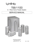
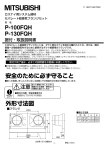
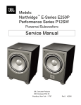
Project Array
™
1500 Array
Subwoofer
Service Manual
JBL Consumer Products
250 Crossways Park Dr.
Woodbury, New York 11797
Rev0 4/2006
1500 Array Subwoofer
- CONTENTS BASIC SPECIFICATIONS …………….……..…………..1
PACKING……..……......................................................2
DETAILED SPECIFICATIONS ……….……..…………..3
CONNECTIONS………………………...……..…...…..…5
OPERATION ……..………………….……...…….….…...6
BASIC TROUBLESHOOTING……………………………7
EXPLODED VIEW/PARTS LIST…….….….…………....8
TEST SET-UP AND PROCEDURE….………………….9
BLOCK DIAGRAM….…………………………………….10
ELECTRICAL PARTS LIST……………………………..11
P.C.B. DRAWINGS….……………...........................….16
IC/TRANSISTOR PINOUTS..……..….…….….….….….22
SCHEMATICS…………………….………………………23
1500 ARRAY SPECIFICATIONS
General
Output
1000W
Low-Frequency Transducer
W1500H 15" Pulp-cone driver
Frequency Response (-3dB)
25Hz – 400Hz, variable
Crossover Frequencies
40Hz-140Hz HP
Port
4" Flared
Dimensions (H x W x D)
23" x 19-1/2" x 19" (584mm x 495mm x 483mm)
21" (533mm) Deep with grille
Weight
125 lb (57kg)
JBL continually strives to update and improve existing products, as well as create new ones. The
specifications and details in this and related JBL publications are therefore subject to change without
notice.
1
1500 Array Subwoofer
2
Ref#
Part Number
Description
1
2
3
4
5
6
361041-002
331994-001
361408-001
354374-001
354374-001
340805-006
1500 Array Owner’s Manual
JBL Warranty Card
1500 Array Outer Carton
Packing Foam (Top)
Packing Foam (Bottom)
(Plate) Feet
Qty
1
1
1
1
1
4
1500 Array Subwoofer
1500 Array Powered Sub/ Plate Amp
LINE VOLTAGE
US 120VAC/60Hz
EU 230VAC/50-60Hz
Asia 100VAC/50Hz
Parameter
Amp Section
Type (Class AB, D, other)
Load Impedance (speaker)
Rated Output Power
THD @ Rated Power
THD @ 1 Watt
Yes/No
YES
YES
YES
Hi/Lo Line
108-132
207-264
90-110
Nom.
120
230
100
Specification
Unit
QA Test
Limits
n/a
Ohms
Watts
%
%
n/a
n/a
593
1
0.2
D
8
650
0.5
0.1
Unit
Vrms
Vrms
Vrms
Notes
Normal Operation
Normal operation, MOMS required
Normal operation, MOMS required
Conditions
Notes
Bridge type amplifier, None of the speaker terminals
must be connected to system GND at any time.
Nominal
1 input driven
22K filter
22K filter
Test frequency 100 Hz
Dynamic Power
DC Offset
700
20
Watts
mV-DC
690
100
Damping factor
>20
DF
15
Power is the average measurement
of the first four consecutive peaks of 3/20 Cycles @ 50 Hz, burst test into 8 Ohms, input
the burst signal
driven with 800mV RMS
@ Speaker Outputs
Measured at the speaker cable. 500 Watts,
measured at speaker output terminals located at the
amp board.
Measured at amplifier board
Input Sensitivity
Input Frequency
100
Hz
100
Nominal Freq.
mVrms
±2dB
Line level input
11.69
Single input driven, Ap Zo=600 Ohms, LFE mode,
Volume ctrl. at max.
To 1 Watt
Signal to Noise
SNR-A-Weighted
SNR-unweighted
SNR rel. 1W-unweighted
100
95
70
dBA
dBr
dBr
95
90
65
Residual Noise Floor
0.5
mVrms
1
Relative to rated power (650 Watts) A-Weighting filter
Relative to rated power (650 Watts) 22K filter
Relative to 1W Output
22K filter
Volume @max, LFE Mode, using
RMS reading DMM/VOM (or A/P)
1
Volume @max, LFE Mode, w/ A/P
Swept Bandpass Measurement
(Line freq.+ harmonics)
Residual Noise Floor
0.5 mVrms(max)
Input Impedance
Line Input
Filters
LP 4th order variable
Subsonic filter (HPF) 3rd Orde
LFE Mode
Features
Line Level output
Volume pot Taper (lin/log)
Variable crossover 40-140 Hz
LP Selector switch LFENormal
Phase switch
Auto- On-Off selector
Input Configuration
Single Line input
10K
ohms
40-140 Hz
Fixed Hz
Fixed Hz
YES
LOG
--
YES
n/a
Nominal
± 10
± 10
± 10
LP Mode switch at LFE
functional
functional
functional
RCA Line buffered line level output
A Taper
4th Order LP Filter, 2nd order fix and 2nd order
variable.
YES
YES
YES
--
functional
functional
functional
Pass through from the speaker input section
Disables LP filter, intended for LFE
Switch located at the back panel
YES
--
functional
Single RCA jack (BLK Color)
Line output configuration
Single Line level output
YES
Signal Sensing (ATO)
Auto-Turn-On (yes/no)
ATO Input test frequency
ATO Level, Line Input
YES
50
2.5
ATO Turn-on time
Auto Mute/ Turn-OFF Time
Power on Delay time
ATO mode
ON mode
Gain=0dB respect to line level input,
Functional Zo=600 Ohms
Single RCA jack (BLK Color)
Hz
mV
2
seconds
15
minutes
4
2
sec.
sec.
functional Auto - on selection switch in Auto
functional
"
functional
"
Amp connected and AC on, then
functional input signal applied
(T) Time before muting, after input
17
signal is removed
Auto turn of time (T) must be 10 > T < 17 Minutes
5
2
After applying the minimum ATO voltage (2mVRMS)
After turning the stand-by knob to ON position
3
1500 Array Subwoofer
Parameter
Transients/Pops
ATO Transient
Turn-on Transient
Turn-off Transient
Specification
Unit
5
50
50
mV-peak
mV-peak
mV-peak
73
%
QA Test
Limits
Conditions
n/a
@ Speaker Output
1V-pk-pk @ Speaker Output
1V-pk-pk @ Speaker Output
Notes
AC Line cycled from OFF to ON
AC Line cycled from ON to OFF
Efficiency
Efficiency
Stand-by Input Power
Stand-by Input Power
Power Cons. @ 500W
3
2
10
678
70
Watts
Watts
8
714
500W of output power into rated
impedance
@ nominal line voltage, Amp in
OFF state, RED LED activated
Nominal Line voltage
Maximum allowable input power LED in RED,
Class D inactive
@ nom. line voltage, Amp in On
state, Green LED activated
@ nom. line voltage
Maximum allowable input power under nominal
Input voltage and frequency, in stand-by mode
(HOT or COLD operation, LED GREEN). Class D
active but no stimulus signal applied.
500 Watts into rated impedance 8 Ohms
Protection
Thermal Protection
DC Offset Protection
Line Fuse Rating
Japan 100V & USA- Versions
Europe 220-240V
functional @1/8 max unclipped Power
DC present at Speaker Out leads
YES
YES
6.3
3.15
Amps
Amps
Temperature rise in accessible metal parts should
not exceed 35K rise for domestic version or 30K
rise for European versions (refer to requirements
sheet). Unit is protected for over-temperature
conditions
Relay opens during a DC output condition
Type-T or Slo Blo-250 V
UL, PSE Approved
Type-T, Low breaking capacity-250VSEMKO Approved
4
Project Array OM
1/10/06
12:21 PM
Page 8
1500 Array Subwoofer
SPEAKER CONNECTIONS
Subwoofer Controls and Connections (15 0 0 Array Only)
¡ Line-Level Input
2
3
4
5
6
™ Line-Level Output
7
0
£ Power Indicator
1
¢ Subwoofer Level (Volume) Control
∞ Crossover Adjustment
§ Phase Switch
¶ LP/LFE Selector
• On/Off Auto Switch
ª Power Switch
Connection:
If you have a Dolby® Digital or DTS®
receiver/processor with a low-frequencyeffects (LFE) output, set LFE/LP switch to
LFE. If you prefer to use the crossover
built into the 1500 Array, set the LFE/LP
Switch ¶ to LP.
8
SUBWOOFER OR
LFE OUTPUT
The 1500 Array includes
a line output. This output
allows you to “daisy chain”
one 1500 Array to multiple
1500 Array subwoofers.
Simply connect the first
subwoofer as described
above and then run a
subwoofer cable from the
line output(s) to the line
input on the next sub.
SUBWOOFER OR
LFE OUTPUT
5
Project Array OM
1/10/06
12:21 PM
Page 9
1500 Array Subwoofer
1500 ARRAY OPERATION
Power On
Plug your subwoofer’s AC cord
into a wall outlet. Do not use
the outlets on the back of the
receiver.
Initially set the Subwoofer
Level (Volume) Control ¢ to
the “min” position.
Turn on your sub by pressing
the Power Switch ª on the
rear panel.
Auto On/Standby
With the Power Switch ª
in the “on” position, the Power
Indicator LED £ will remain
backlit in red or green to
indicate the On/Standby
mode of the subwoofer.
RED = STANDBY (No signal
detected, Amp Off)
GREEN = ON (Signal detected,
Amp On)
The subwoofer will automatically enter the Standby
mode after approximately 10
minutes when no signal is
detected from your system.
The subwoofer will then power
ON instantly when a signal is
detected. During periods of
normal use, the Power Switch
ª can be left on. You may turn
off the Power Switch ª for
extended periods of nonoperation, e.g., when you are
away on vacation.
If the Auto Switch • is in the
“on” position, the subwoofer
will remain on.
Adjust Level
Turn on your entire audio
system and start a CD or movie
soundtrack at a moderate
level. Turn up the Subwoofer
Level (Volume) Control ¢
about halfway. If no sound
emanates from the subwoofer,
check the AC-line cord and
input cables. Are the connectors on the cables making
proper contact? Is the AC
plug connected to a “live”
receptacle? Has the Power
Switch ª been pressed to
the “on” position? Once you
have confirmed that the subwoofer is active, proceed by
playing a CD or movie. Use a
selection that has ample bass
information.
Set the overall volume control
of the preamplifier or stereo
to a comfortable level. Adjust
the Subwoofer Level (Volume)
Control ¢ until you obtain a
pleasing blend of bass. Bass
response should not overpower the room but rather
should be adjusted so there is
a harmonious blend across the
entire musical range. Many
users have a tendency to set
the subwoofer volume too
loud, adhering to the belief
that a subwoofer is there to
produce lots of bass. This is
not entirely true. A subwoofer
is there to enhance bass,
extending the response of
the entire system so the bass
can be felt as well as heard.
However, overall balance
must be maintained or the
music will not sound natural.
An experienced listener will
set the volume of the subwoofer so its impact on bass
response is always there but
never obtrusive.
Crossover Adjustments
NOTE: This control will have
no effect if the LP/LFE Selector
Switch ¶ is set to “LFE.” If
you have a Dolby Digital or
DTS processor/receiver, the
Crossover Frequency is set
by the processor/receiver.
Consult your owner’s manual
to learn how to view or change
this setting.
The Crossover Adjustment
Control ∞ determines the
highest frequency at which the
subwoofer reproduces sounds.
6
If your main speakers can
comfortably reproduce some
low-frequency sounds, set this
control to a lower frequency
setting, between 50Hz and
100Hz. This will concentrate
the subwoofer’s efforts on
the ultradeep bass sounds
required by today’s films and
music. If you are using smaller
bookshelf speakers that do
not extend to the lower bass
frequencies, set the Crossover
Adjustment Control to a higher
setting, between 120Hz and
150Hz.
Phase Control
The Phase Switch § determines whether the subwoofer
speaker’s pistonlike action
moves in and out with the main
speakers (0˚) or opposite the
main speakers (180˚). Proper
phase adjustment depends
on several variables, such as
subwoofer placement and
listener position. Adjust the
Phase Switch to maximize
bass output at the listening
position.
1500 Array Subwoofer
BASIC TROUBLESHOOTING
If there is low (or no) bass output
•
Make sure the connections to the left and right “Speaker
Inputs” have the correct polarity (+ and –).
•
Make sure the subwoofer is plugged into an active electrical
outlet.
•
Make sure the Power Switch is on.
•
In Dolby Digital or DTS modes, make sure your
receiver/processor is configured so that the subwoofer
and LFE output are enabled.
•
Adjust the Subwoofer Level Control
7
1500 Array Subwoofer
1500 ARRAY SUB EXPLODED VIEW
X RAY VIEW FOR
ILLUSTRATIVE PURPOSES ONLY
DAMPING MATERIAL NOT SHOWN
1500 ARRAY MECHANICAL PARTS LIST
Item #
8
1
2
3
4
5
6
7
8
9
10
11
12
13
Description
Part Number
Qty
CABINET ASSEMBLY-1500 ARRAY
15" WOOFER-W1500H
AMPLIFIER ASSEMBLY,120V-ARRAY
POWER TRANSFORMER-1500 ARRAY BG
PORT TUBE -1500 ARRAY
CARBOARD TUBE,4 1/4x4x1/8x6-4338
FOOT,NUT,INSERT,BLK
FOOT,SPIKE,BLK
GRILLE,FRONT, 1500 ARRAY
WOOFER SCREW,10-32 X 1,FIL,PH,BLK ZINC,LCS
AMPLIFIER SCREW,8 X 1,PAN,PH,PB,BLK ZINC,LCS
GASKET,DRVR,15"
LOGO-JBL
Not for Sale
353721-001
Not for Sale
361407-001
360806-001
47909-68
340805-004
340805-005
354507-001
804-01110-16
883-41110-16
338073-001
360813-001
1
1
1
1
1
1
4
4
1
8
10
1
1
1500 Array Subwoofer
1500 Array TEST PROCEDURE
Equipment needed:
• Function/signal generator/sweep generator
• Multimeter
• RCA cable
General Unit Function (UUT = Unit Under Test)
Switch/Controls:
GAIN control full Counterclockwise (Min)
CROSSOVER (Hz) Full Clockwise (140)
PHASE switch - either position
LFE/LP – LP position
1)
2)
3)
4)
5)
6)
From the signal generator, connect one line level (RCA) cable to the Line In jack on the UUT.
Turn on generator; adjust to 200mV, 50 Hz.
Plug AC power cord in UUT, turn power switch ON.
LED should be ON (faceplate). Turn up LEVEL control to full Clockwise (Max).
LED should be Green; Bass response should be heard and felt vigorously from woofer and port tube.
Turn LEVEL control full Counterclockwise (Min). Turn power switch OFF.
Sweep Function
1) Follow steps 1-5 above, using a sweep generator as a signal source – adjust the generator to 75mV, 50 Hz.
2) Sweep generator from 20Hz to 300Hz. Listen for any rattles, clicks, buzzes or any other noises. If any unusual
noises are heard, test woofer according to the instructions below.
Driver Function
1) Remove woofer from the enclosure.
2) Check DC resistance of woofer; it should be 5.9 Ω ±10%,
3) Connect a pair of speaker cables to woofer terminals. Cables should be connected to an integrated amplifier
fed by a signal generator. Turn on generator and adjust so that speaker level output is 6.0V.
4) Sweep generator from 20Hz to 1kHz. Listen to driver for any rubbing, buzzing, or other unusual noises.
9
1500 Array Subwoofer
1500 ARRAY BLOCK DIAGRAM
10
1500 Array Subwoofer
1500 Array 120V Electrical parts list
Part number
Qty Description
Reference Designator
DRIVER PCB
Resistors
024-000098-120ZS
024-100298-120ZS
024-100498-120ZS
024-100598-120ZS
024-110598-120ZS
024-200598-120ZS
024-220398-120ZS
024-220498-121ZS
024-220598-120ZS
024-220798-120ZS
024-270498-120ZS
024-390498-120ZS
024-390598-120ZS
024-470398-120ZS
024-470498-120ZS
024-470598-120ZS
024-470698-120ZS
024-560598-120ZS
024-680498-120ZS
4
4
10
12
2
4
2
1
1
2
3
2
2
1
4
1
2
1
2
GS SMD Resistor 0R 1/8W J 0805
GS SMD Resistor 10R 1/8W J 0805
GS SMD Resistor 1K 1/8W J 0805
GS SMD Resistor 10K 1/8W J 0805
GS SMD Resistor 11K 1/8W J 0805
GS SMD Resistor 20K 1/8W J 0805
GS SMD Resistor 220R 1/8W J 0805
GS SMD Resistor 2K2 1/8W J 0805
GS SMD Resistor 22K 1/8W J 0805
GS SMD Resistor 2M2 1/8W J 0805
GS SMD Resistor 2K7 1/8W J 0805
GS SMD Resistor 3K9 1/8W J 0805
GS SMD Resistor 39K 1/8W J 0805
GS SMD Resistor 470R 1/8W J 0805
GS SMD Resistor 4K7 1/8W J 0805
GS SMD Resistor 47K 1/8W J 0805
GS SMD Resistor 470K 1/8W J 0805
GS SMD Resistor 56K 1/8W J 0805
GS SMD REsistor 6K8 1/8W J 0805
R313,314,318,320
R89,90,140,150
R81,85,96,97,131,137,142,147,162,179
R75,83,92,98,132,133,151,156,163,164,183,82,
R74,99
R95,141,148,181
R136,167
R134
R37
R87,93
R80,84,157
R130,161,
R86,94
R91
R34,36,152,153
R35
R32,33
R38
R135,166
4
2
6
2
4
4
1
1
GS SMD Ceramic cap. 0u01/50V K 0805 X7R
GS SMD Cap. 100pF/50V J 0805 NPO
GS SMD Cap. 0u1/50V K 0805 X7R
GS SMD Cap. 0u18/50V K 0805 X7R
GS SMD Cap. 0u047/50V K 0805 X7R
GS SMD Cap. 56pF/50V J 0805 NPO
GS SMD Cap. 560pF/50V J 0805 NPO
GS Elec. Cap. 100uF/16V M (R)0611 P:2.5
C108,118,131,140
C81,84
C75-78,82,85
C80,83
C93,94,101,124
C92,102,105,125
C79
C117
2
1
2
2
2
2
5
2
1
2
2
1
2
GS SMD DIODE: PN:ES1D 200V 1A
GR SMD ZENER DIODE PN:BZV55C3V6 (PHILIPS)
GS SMD IC: (JRC) M072M-DUAL OP-AMP
GR SMD ZEN DIODE:(PHILIPS) BZX84C10-7-F SOT-23
GR SMD ZEN DIODE:(PHILIPS) BZX84C5V6-7-F SOT-23
GR SMD Transistor (ON) PN:MMBT3906LT1G SOT23
GS SMD DIODE: PN:LL4148 MINI-MELF
GR SMD Transistor PNP (ON SEN) MMBT5401 LT1 SOT-23
GR SMD Transistor (NPN) PN:MMBT5551 LT1R (ON)
GR Transistor NPN (ON SEM) PN:MPS2222ARLRAR TO-92
GR Transistor NPN PN:2N5551 TO-92
GR Transistor NPN PN:MPSW06RLRA TO-92 (ON)
GR IC:DIP,HALF-BRIDGE DRIVER PN:IR2111 8PIN (IR)
D35,43
D60
U9,10
D42,49
Z7,8
Q34,35
D36,39,46,52,61
Q33,40
Q32
Q20,22
Q21,23
Q31
U7,8
1
1
GR HEADER Right Angle PN:211-107-000-400 7PIN
GR HEADER Right Angle PN:211-111-000-400 11PIN
PIN2
PIN1
5
4
15
1
1
5
1
GS SMD Resistor PN:1206J000 0R 1/4W J 1206
GS SMD Resistor PN:1206F102 1K 1/4W F 1206
GS SMD Resistor 10K 1/4W J 1206
GS SMD Resistor 1K5 1/4W J 1206
GS SMD Resistor 15K 1/8W F 0805
GS SMD Resistor PN:1206F203 20K 1/4W F 1206
GS SMD Resistor 22R 1/4W J 1206
R258,290,297,302,303,
R238,264,288,291
R202,206,207,212,222,235,252-254,257,228,229,262,268,284
R251
R223,
R256,208,209,231,232
R249
Capacitors
031-100244-100ZS
031-100343-100ZS
031-100344-100ZS
031-180344-100ZS
031-470244-102ZS
031-560243-100ZS
031-560343-102ZS
034-100614-300ZS
Semiconductors
054-000100-100ZS
054-005501-100ZR
054-007200-100LZS
054-008406-000ZR
054-008408-000ZR
054-033906-100ZR
054-414803-100ZS
054-540100-100ZR
054-555100-100ZR
051-222200-100ZR
051-555100-000ZR
051-000600-100ZR
053-211100-000ZR
Miscellaneous
072-040229-000ZR
072-040230-000ZR
PREAMP PCB
Resistors
024-000097-120ZS
024-100497-100ZS
024-100598-121ZS
024-150498-121ZS
024-150598-100ZS
024-200597-100ZS
024-220298-121ZS
11
1500 Array Subwoofer
Part number
Qty Description
Reference Designator
PREAMP PCB
024-220397-120ZS
024-237598-120ZS
024-270498-121ZS
024-330397-120ZR
024-330498-121ZS
024-330598-121ZS
024-365697-100ZR
024-402597-100ZS
024-432598-100ZR
024-470598-121ZS
024-470698-121ZS
024-470797-100ZS
024-536597-100ZR
024-560598-121ZS
024-620398-121ZS
024-680498-121ZS
024-680598-121ZS
024-820598-121ZS
021-432598-100ZS
021-475498-100ZR
026-500495-005ZS
026-500595-267ZS
1
1
1
2
1
4
1
1
1
1
1
2
1
1
2
1
1
1
1
1
1
1
GS SMD Resistor 220R 1/4W J 1206
GS SMD Resistor 23K7 1/8W F 0805
GS SMD Resistor 2K7 1/4W J 1206
GR SMD Resistor 330R 1/4W J 1206
GS SMD resistor 3K3 1/4W J 1206
GS SMD resistor 33K 1/4W J 1206
GR SMD resistor 365K 1/4W F 1206
GS SMD resistor 40K2 1/4W F 1206
GR SMD resistor 43K2 1/8W F 0805 TPAING
GS SMD resistor 47K 1/4W J 1206
GS SMD resistor 470K 1/4W J 1206
GS SMD resistor 4M7 1/4W F 1206
GR SMD resistor 53K6 1/4W F 1206
GS SMD resistor 56K 1/4W J 1206
GS SMD resistor 620R 1/4W J 1206
GS SMD resistor 6K8 1/4W J 1206
GS SMD resistor 68K 1/4W J 1206
GS SMD resistor 82K 1/4W J 1206
GS Metal film 43K2 1/8W F
GR MF resistor 4K75 1/8W F
GS VR 5K PN:RD163111R22B-5K15A-EJ GAIN
GS VR 50KBx4 PN:RD1631411001D-50KBx4
R255
R281
R237
R211,282
R240
R298,406,408,414
R285
R260
R214
R280
R259
R244,243
R283
R224
R221,226,
R247
R250
R263
R214
R204
R216
R233
2
8
1
3
1
1
2
1
2
1
6
1
1
2
2
1
2
GS SMD cap. 0u01/50V K 1206 X7R
GS SMD cap. 0u1/50V K 1206 X7R
GS SMD cap. 100pF/50V K NPO 1206
GS SMD cap. 220pF/50V K X7R 1206
GR SMD cap. 0u027/50V K 0805 X7R
SMD cap. 2700pF/50V K 1206 X7R
GS SMD cap. 0u0047/50V K 0805 X7R
GS SMD cap. 0u0068/50V K 0805 X7R
GS elec. Cap. 10uF/16V M (R)0511 P:2.5 TAPIN
GS Elec. Cap. 100uF/16V M (R)0611 P:5
GS elec. Cap. 22uF/16V M (R)0511 P:2
GS PE Cap. 0uF1/50V J P:5
GR PE Cap. FE-M 0u022/63V J P:5m/m
GR PE Cap. PN:ESK063S33JT 0u033/63V J P:5
GR PE Cap. P:5 0u47/63V J P/N:R82DC347DQJ
GR PE Cap. FE-M PN:ESK063S68JT 0u068/63V J P:5mm
GS NPE cap. 33uF/16V M (R)0511 P:2
C12,13
C227,229,230,232-235,200
C222
C215,216,204
C280
C224
C2G1,C281
C212
C220,237
C221
C223,416,14,15,411,415
C213
C202
C209,218
C207,208
C201
C214,225
6
1
2
14
1
1
1
GS SMD IC: (JRC) M072M-DUAL OP-AMP
GR SMD Transistor PN:DTC114TKA SMT3 (ROHM
GR SMD Transistor (SC00044) PN:MMBT3904TR(Fairchild)
GS SMD DIODE: PN:LL4148 MINI-MELF
GR SMD ZENZER DIODE: (GMT) GMBZ5237B 8V2 SOT23
GS LED PN:LT-2402-21
GR JFET N-Channel PN:J111 TO-92 (FAIRCHILD
U200-205
Q202
Q203,204
D201,204,207,209,212,216,218,219,405,413,414,217,203,200,
D206
LED1
Q200
1
1
2
1
GR RCA JACK PN:B217CK
GS Terminal housing PN:JS-1001-08 8P P:2.5
GR TOGGLE SW PN:L101-T2B4QE LFE, PHASE
GR TOGGLE SW PN:L103-T2-B4 AUTO ON-OFF
J201
P2
SW201,202
SW200
2
1
3
1
2
1
GS FUSE CLIP P/N:CT-FH1206
GR FUSE T6.3A/250V GSL-6.3 φ5x20m/m
GR (PCB TYPE) PC205 (t=0.8m/m) T205MA
GR Terminal (PCB TYPE) PC250 (t=0.8m/m) T250MA
Capacitors
031-100244-101ZS
031-100344-102AZS
031-100344-104AZS
031-220344-106AZS
031-270244-100ZR
031-270444-101
031-470144-101AZS
031-680144-100ZS
034-100515-304ZS
034-100615-301ZS
034-220516-301ZS
035-100343-300ZS
035-220243-100ZR
035-330293-300ZR
035-470353-302ZR
035-680253-300ZR
033-330515-300ZS
Semiconductors
054-007200-100LZS
054-011400-100ZR
054-390402-100ZR
054-414803-100ZS
054-523701-100ZR
050-505200-001ZS
051-011100-100ZR
Miscellaneous
072-010360-000ZR
072-040008-110ZS
074-030002-000ZR
074-030018-000ZR
FUSE PCB
073-050001-000ZS
091-000132-000ZR
072-040039-000ZR
072-040064-000ZR
039-220384-100ZR
043-155300-000ZR
for F1
F1
T2,TER5,6,
TER1
GR X2 Safety Cap. 0u22/250V HQX0.22K275VX2 18x16.5x8.5 CXAC1,CXAC2
GR COIL PN:YT-13192 155uH±10%
L7
12
1500 Array Subwoofer
Part number
Qty Description
Reference Designator
FUSE PCB
043-324300-000ZR
025-006000-000ZR
1
1
GR INDUCTOR 324uH YT-10778
GR Thermister P/N:CL-60
L13
TH3
3
4
1
1
2
4
3
2
1
1
1
6
2
GS END Mylar cap. 1uF/250V K P:15
GR Elec. Cap. (LP) 85℃ 6800uF/80V M (R)3050 P:10
GR Ceramic cap. 180pF/250V K X7R P:5
GS SMD Cap. 0u22/100V K 1206 X7R
GS SMD cap.0u1/250V K 1206 X7R
GS SMD cap. 0u1/50V K 1206 X7R
GS SMD cap. 0u01/50V K 1206 X7R
GS electrolytic cap. 220uF/25V M (R)0812 P:5
GS elec. Cap. 330uF/25V M (R)1013 P:5
GS electrolytic cap. 4u7/50V M (R)0511 P:2.0
GR elec. Cap. 47uF/16V M (R)0511 P:2.5
GS electrolytic cap. 22uF/16V M (R)0511 P:2
GR ESK mylar cap. 1u/100V K P:5
C410,418,427
C420-423,
C419( in series with R403 T400 pin2-5)
C424
C428,429
C417,401-403,
C404-406
C414,413
C412
C407
C408
C223,416,14,15,411,415
C425,426
1
2
2
4
1
GR FUSIBLE RES 100R 1W J
GS SMD resistor 9K1 1/8W J 0805
GS SMD resistor 470R 1/4W J 1206
GS SMD resistor PN:1206F103 10K 1/4W F 1206
GS SMD resistor 2K2 1/4W J 1206
R403(C419 in sereis with C403 T400 pin2-5)
R413,415
R401,402
R409,416,417,405
R400
3
4
1
1
1
1
1
1
1
GR SMD ZEN DIODE:(PHILIPS) PN:BZX84C15-7-F SOT-23
GR GS SMD DIODE: PN:ES1D 200V 1A (PANJIT)
DIODE TVZ:DIP PN:P6KE130A (CONCORD)
GR transistor NPN PN:MPSW06RLRA TO-92 (ON)
GR transistor PNP PN:MPSW56RLRAR TO-92 (ON
GS transistor NPN PN:TIP 31C TO-220 (MOSPEC)
GR SMD Transistor (SC00044) PN:MMBT3904TR(Fairchild)
GR bridge rectifier PN:GBJ1504
IC:DIP PN:TOP102YAI (PWM Switch)
D400,402,403
D406-409
D404
Q406
Q408
Q404
Q402
BR400
U400
3
1
1
2
1
GS SMD FERRITE BEAD PN:321611 600R/100MHz 1206
GS SMD FERRITE BEAD PN:321611 800R/100MHz 1206
GR INDUCTOR 56uH YT-10779
GR Terminal (PCB TYPE) PC250 (t=0.8m/m) T250MA
GR X'former PN:YT-13167 KAPPA-1000
FB403-405
FB406
L400
TER401,404
T400
POWER PCB
Capacitors
032-100484-200ZS
034-680794-200ZR
030-180384-300ZR
031-220364-100ZS
031-100384-100RZS
031-100344-102AZS
031-100244-101ZS
034-220625-300ZS
034-330625-300ZS
034-470415-300ZS
034-470515-200ZR
034-220516-301ZS
035-100464-300ZR
Resistors
028-100301-020ZR
024-910498-120ZS
024-470398-121ZS
024-100598-101ZS
024-220498-120ZS
Semiconductors
054-008407-000ZR
054-000100-100ZR
050-013000-100
051-000600-100ZR
051-005600-100ZR
051-003100-000ZS
054-390402-100ZR
052-150400-000ZR
053-010200-000
Miscellaneous
044-100100-000ZS
044-100103-000ZS
043-560200-000ZR
072-040064-000ZR
042-010115-000ZR
DAUGHTER PCB (Attached to Power PCB)
054-033904-100ZR
054-033906-100ZR
054-414803-100ZS
024-100598-120ZS
024-220298-120ZS
034-100444-300ZR
072-040337-000ZR
1
1
1
2
1
1
1
SMD (TRANSISTOR) PN:MMBT3904LT1G SOT23 ING
SMD transistor (ON) PN:MMBT3906LT1G SOT23 ING
GS SMD DIODE:PN:LL4148 MINI-MELF ING
GS SMD resistor 10K 1/8W J 0805 ING
GS SMD resistor 22R 1/8W J 0805 ING
GR electrolytic cap. 1uF/50V K (R)0511 P:5 TAING
HEADER Right Angle PN:211-110-000-400 10PIN
Q403B
Q405B
D410B
R404B,R407B
R412B
C430B
CONNECT
1
17
1
1
GS SMD resistor 1K 1/8W J 0805
GS SMD resistor 10K 1/8W J 0805
GS SMD resistor 100K 1/8W J 0805
GS SMD resistor 13K 1/8W J 0805
R119
R1,4,7,16,121-123,126,128,138,165,168,170,125,143,169,19,
R120
R118
MAIN PCB
Resistors
024-100498-120ZS
024-100598-120ZS
024-100698-120ZS
024-130598-120ZS
13
1500 Array Subwoofer
Part number
Qty Description
Reference Designator
MAIN PCB
024-150598-100ZS
024-220298-121ZS
024-220498-121ZS
024-220598-120ZS
024-332498-100ZS
024-332598-101ZS
024-392498-100ZR
024-470398-120ZS
024-470598-120ZS
024-560298-120ZS
024-560498-120ZS
024-560598-120ZS
024-680498-120ZS
2
2
4
1
1
2
1
4
2
4
1
1
1
GS SMD resistor 15K 1/8W F 0805
GS SMD resistor 22R 1/4W J 1206
GS SMD resistor 2K2 1/8W J 0805
GS SMD resistor 22K 1/8W J 0805
GS SMD resistor 3K32 1/8W F 0805
GS SMD resistor 33K2 1/8W F 0805
GR SMD resistor 3K92 1/8W F 0805
GS SMD resistor 470R 1/8W J 0805
GS SMD resistor 47K 1/8W J 0805
GS SMD resistor 56R 1/8W J 0805
GS SMD resistor 5K6 1/8W J 0805
GS SMD resistor 56K 1/8W J 0805
GS SMD resistor 6K8 1/8W J 0805
R20,21
R28,29
R17,31,110,139
R127
R22
R60,60B
R63
R145,155,177,186
R3,171
R24-27
R30
R15
R23
1
2
1
7
1
1
1
1
2
1
5
2
2
2
1
2
1
1
GS SMD cap. 0u001/50V K 0805 X7R
GS SMD cap. 0u01/50V K 0805 X7R
GS SMD cap. 0u1/50V K 0805 X7R
GS SMD cap. 0u1/100V K 1206 X7R
GS SMD cap. 0u1/250V K 1206 X7R
GS SMD cap. 220pF/50V K 0805 NPO
GS SMD cap. 0u0047/50V K 0805 X7R
GS SMD cap. 470pF/50V K 0805 X7R
GS elect. Cap. 1000uF/16V M (R)1017 P:3.5
GS elec. Cap. 330uF/16V M (R)0812 P:3.5 loose package
GS END mylar cap. 1uF/250V K P:15
GS NPE cap. ELYTONE 3u3/63V K10 (R) 8x13 TBE
GS NPE cap. 印ELYTONE 6u8/100V K10 (R)1020 GNE
GR elec. Cap. (LP) 85℃ 8200uF/80V M (R)3545 P:10
GS elect. Cap. 100uF/25V M (R)6.3x11 P:5
GR elec. Cap. 22uF/25V M (R)5x11 P:2.5 TAPIN
GS elect. Cap. 220uF/16V M (R)0611 P:2.5
GS elec. Cap. 220uF/25V M (R)0812 P:5
C130
C27,28
C116
C5,6,69,112,115,135,138
C39B
C40
C1G1
C123
C109,132
C32
C30,37,39,C31,38
C114,137
C113,136
C1,4
C62
C25,26
C8
C100
2
1
1
GS MOF resistor 1K 2W J FK TYPE
GS resistor PN:SQM 0R05 5W J 25x13
GS film resistor 2K2 1/2W J
R173,48
R2
R6
5
1
7
2
1
15
3
1
4
4
1
GS SMD DIODE: PN:ES1D 200V 1A
GR SMD ZENER DIODE:(PHILIPS) BZX84C3V0-7-F SOT-23
GR SMD (TRANSISTOR) PN:MMBT3904LT1G SOT23
GR SMD transistor (ON) PN:MMBT3906LT1G SOT23
GR SMD transistor (ON) PN:MMBT2907ALT1 SOT-23
GS SMD DIODE:PN:LL4148 MINI-MELF
GR SMD transistor PNP (ON SEN) MMBT5401 LT1 SOT-23
GR SMD transistor (NPN) PN:MMBT5551 LT1R (ON)
GR MOSFET N-CHANNEL PN:2SK3594-01SC (FUJI)
GR Transistor PNP (ON) PN:MPS2907A RLRAR TO-92
GR Transistor PNP(FAIRCHILD PN:2N5401 TO-92
D23,37,40,44,47
D32
Q28,29,50,51,127,128,130
Q30,38
Q52
D1,4-6,21,22,31,33,34,38,41,45,48,53,54
Q1,2,26
Q25
Q11,13,15,17
Q12,14,16,18
Q3
8
2
1
1
1
2
1
1
1
2
1
GR terminal (PCB TYPE) PC205 (t=0.8m/m) T205MA
GS SMD FERRITE BEAD PN:321611 600R/100MHz 1206
GR thermister PN:NTSE103KZ072 K L:50mm
GS thermister (PTC) PN:PTMS2101RP516Y
GR COIL PN:YT-13141 110uHx2±10%
GR INDUCTOR PN:YT-10033 30uH
GR INDUCTOR 56uH YT-10779
GS terminal housing SWA101 PN:JS-1001-07 7P
GS terminal housing PN:JS-1001-08 8P P:2.5
GR terminal (PCB TYPE) PC250 (t=0.8m/m) T250MA
GR shorting strap 54.9x13.6x1mm
TER402,403,406,407,TER2,4,8,3
FB1,2
TH1
TH2
L8 (L8+L11)
L9,10
L12
P9
P1
T1,TER7
J7
Capacitors
031-100144-103ZS
031-100144-106ZS
031-100344-100ZS
031-100364-100ZS
031-100384-100RZS
031-220344-300ZS
031-470144-101ZS
031-470344-100ZS
034-100715-300ZS
034-330615-301ZS
032-100484-200ZS
033-330494-270ZS
033-680464-270ZS
034-820794-200ZR
034-100625-300ZS
034-220525-300ZR
034-220615-300ZS
034-220625-300ZS
Resistors
021-100402-021ZS
022-005105-020ZS
020-220496-100ZS
Semiconductors
054-000100-100ZS
054-008409-000ZR
054-033904-100ZR
054-033906-100ZR
054-290701-100ZR
054-414803-100ZS
054-540100-100ZR
054-555100-100ZR
051-359400-000ZR
051-290700-100ZR
051-540101-000ZR
Miscellaneous
072-040039-000ZR
044-100100-000ZS
025-010300-000ZR
025-210100-000ZS
043-110300-000ZR
043-300101-000ZR
043-560200-000ZR
072-040007-000ZS
072-040008-110ZS
072-040064-000ZR
073-111003-000ZR
14
1500 Array Subwoofer
Part number
Qty Description
Reference Designator
Mechanical Parts
073-111004-000ZR
074-300018-000ZR
1
1
GR shorting strap 29.5x12.4x0.8m/m
GR RELAY PN:943-1C-48D
J9
K1
008-061215-000ZR
008-061602-022ZR
008-063702-002ZR
008-065757-002ZR
061-001052-000ZS
061-100016-000ZR
061-700044-000ZR
061-700090-900ZR
061-700119-000ZR
061-701003-000ZR
063-010010-000ZR
063-060606-000ZR
063-401602-000ZR
073-014103-500ZR
073-032141-600ZR
074-020005-000ZR
074-020018-000ZR
1 GR GASKET C4305 12x15 t=5mm CR spa
2 GR GASKET CR4305 spa 155.8x16.8 t=1.5mm (UL94-HF1)
2 GR GASKET CR4305 spa 372.3x16.1 t=1.5mm (UL94-HF1)
1 GR GASKET CR4305 spa 56.9x57.2 t=1.0mm (UL94-HF1)
2 GS Knob w/white indicator 49001-W (18 t)D=15.1 H=14.5
7 GR post PN:BCMS-8 L=8mm NYLON 66(UL)
2 GR mica 13x18mm TO-220 holeless
2 GR ceramic washer 16x21mm t=2mm white
1 GR insulator 114.3x84mm t=0.254mm FR700
1 GR insulator w/adhesive M 467 170x85mm t=0.432mm
5 GR Transistor Bracket P/N:TRK-2
1 GR X'FORMER PLATE SPCC 56.9x57.2 t=2.0mm
1 GR Plate SPCC (1500 Array) 402x156.8 t=2.3mm
1 GR Bracket (HB5000) 6.64"x3.5"x3.2" SPCC
1 GR Heatsink (HB5000) 82.8x120.7x19.1mm black anodiz
1 GR 2-pin AC socket P/N 3516-T3C02
1 GR ROCKER SW (AC POWER) PN:RF1003-BB4-0
086-021836-004ZR/120V
1 GR Power cord SJT 16AWGx2C L=3660mm WS004+WS002E
FOR MAIN POWER TRANSFORMER SEE EXPLODED VIEW
15
thermistor
plate x2
Plate x2
X'FORMERPLATE
GAIN, CROSSOVER KNOBS
POWER PCBx4,FUSE PCBx3
for Q13,17
for Q11,15
POWER PCB
bracket+plate
for Q11,13,15,17,TH1
platex1
bracketx1
AC POWER Receptacle
SW4
AC POWER Cord
1500 Array Subwoofer
16
1500 Array Subwoofer
17
1500 Array Subwoofer
18
1500 Array Subwoofer
19
1500 Array Subwoofer
20
1500 Array Subwoofer
21
1500 Array Subwoofer
22
1500 Array Subwoofer
01
02
New Sub design originated from HB5000 Platform
07/25/2005
2006/02/16
23
1
2
3
1500 Array Subwoofer
01
02
New Sub design originated from HB5000 Platform
07/25/2005
2006/02/16
24
1500 Array Subwoofer
01
02
New Sub design originated from HB5000 Platform
07/25/2005
2006/02/16
25
1500 Array Subwoofer
01
2006/02/16
26
1500 Array Subwoofer
27