1
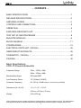
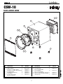
file:///C|/Documents%20and%20Settings/bob/My%20Documents/manualdirectory.htm
This file was downloaded and provided FREE OF CHARGE
from the ManualDirectory community.
You can find many free to download Service Manuals & Schematics at
http://www.manualdirectory.co.uk
file:///C|/Documents%20and%20Settings/bob/My%20Documents/manualdirectory.htm01/04/2007 01:34:00
Beta SW Series
™
CSW-10 Subwoofer
SERVICE MANUAL
Infinity Systems, Inc.
250 Crossways Park Dr.
Woodbury, New York 11797
Rev1
9/2004
CSW-10
- CONTENTS BASIC SPECIFICATIONS
…………………………….………………….………..1
DETAILED SPECIFICATIONS…..……………………………………………….…..2
AMPLIFIER ACCESS………………..………………………………………………..3
CONTROLS AND CONNECTIONS…………………………………….…..………..4
OPERATION….……………………………………………………………………..….6
EXPLODED VIEW/PARTS LIST………………………………..……………....……7
TEST SET UP AND PROCEDURE…………….………..………………..…....……8
BULLETIN INF2004-02…..…………………………………….………………….…..9
BLOCK DIAGRAM…………………………..…………………………………..…….11
PCB DRAWINGS………………………………………………………………..….…12
ELECTRICAL PARTS LIST (120/230v) …………………………………………….20
SEMICONDUCTOR PINOUTS…………………………………….………….……..25
SCHEMATICS (120/230v)…………… …………………………...………………...26
PACKING….……………………………………………………………………………30
Basic Specifications
CSW-10 Powered Subwoofer
Frequency Range:
22Hz – 150Hz (-3dB)
20Hz – 150Hz (-6dB)
Max Amplifier Output:
650 watts RMS
Low-Frequency Driver:
10" (254mm) C.M.M.D.
Crossover Frequency:
50 -150 Hz (24dB/octave, continuously variable)
Dimensions (H x W x D):
14" x 13-1/4" x 15-3/8"
(356mm x 337mm x 391mm)
Weight:
52 lb (23.6 kg)
Infinity continually strives to update and improve existing products, as well as create new ones. The specifications
and construction details in this and related Infinity publications are therefore subject to change without notice.
1
CSW-10
CSW-10
LINE VOLTAGE
US 120VAC/60Hz
EU 230VAC/50-60Hz
Parameter
Amp Section
450W Powered Sub/ Plate Amp
Yes/No
Yes
Yes
Hi/Lo Line
108-132
207-264
Nom.
120
230
Specification
Unit
QA Test
Limits
Type (Class AB, D, other)
Load Impedance (speaker)
Rated Output Power
THD @ Rated Power
THD @ 1 Watt
D
4
450
0.5
0.1
n/a
Ohms
Watts
%
%
n/a
n/a
425
1
0.2
Unit
Vrms
Vrms
Notes
Normal Operation
Normal operation, MOMS required
Conditions
Notes
Bridge type amplifier, None of the speaker
terminals must be connected to system GND at
any time.
Nominal
1 input driven
22K filter
22K filter
Dynamic Power
DC Offset
450
80
Watts
mV-DC
430
100
Damping factor
>20
DF
15
Power is the average measurement 3/20 Cycles @ 50 Hz, burst test into 4 Ohms,
of the first four consecutive peaks of input driven 6dB above its maximum sensitivity,
the burst signal
volume level at Maximum, RABOS Section OFF
@ Speaker Outputs
Measured at the speaker cable. 200 Watts,
measured at speaker output terminals located at
the amp board.
Measured at amplifier board
50
Hz
30
Nominal Freq.
Input Sensitivity
Input Frequency
Left or Right inputs
10.29
mVrms
±2dB
To 1 Watt
Single input driven, Ap Zo=600 Ohms, LP ON,
RABOS OFF, Volume ctrl & crossover at max
Left & Right with LFE or LP
filter OFF Mode selected
10.17
mVrms
±2dB
To 1 Watt
Single input driven , Ap Zo=600 Ohms, LP OFF,
RABOS OFF, Volume ctrl & crossover at max
Speaker/Hi Level Input
158
mVrms
±2dB
To 1 Watt
Single input driven, Ap Zo=25 Ohms, Normal,
RABOS OFF, Volume ctrl & crossover at max
Signal to Noise
SNR-A-Weighted
SNR-unweighted
SNR rel. 1W-unweighted
100
95
70
dBA
dBr
dBr
95
90
65
Residual Noise Floor
0.5
mVrms
1
Residual Noise Floor
0.5 mVrms(max)
Input Impedance
Line Input (L, R,LFE)
Speaker/Hi Level Input
10K
10K
Filters
LP 4th order variable
Subsonic filter (HPF) 3rd Orde
Low pass filter OFF
50-150 Hz
Fixed Hz
Fixed Hz
BOS
Frequency Control
Range
Level Control
Range
Width(Q) Control
Range
Limiter
THD at Max. Output Power
Features
Auto - On -Off
Phase switch
Volume pot Taper (lin/log)
ohms
ohms
1
n/a
n/a
± 10
± 10
± 10
Relative to rated power (400 Watts) A-Weighting filter
Relative to rated power (400 Watts) 22K filter
22K filter
Relative to 1W Output
Volume @max, using RMS reading
DMM/VOM (or A/P)
Volume @max, w/ A/P Swept
Bandpass Measurement (Line
freq.+ harmonics)
Nominal
Nominal
L or R input driven, LP Filter OFF
Refer to AP graph 1
Refer to AP graph 1
Refer to AP graph 1
-20-80 Hz
--14.1 to 0 dB
-4.5% to 49.5% octave
YES
functional 21 detent pot (0.1 oct. steps)
-functional 21 detent pot (0.5dB steps)
-functional 21 detent pot (5steps/0.1 octave)
Refer to AP graph 2
Refer to AP graph 3
Refer to AP graph 4
n/a
functional
-deg
--
functional
functional
functional
--
functional
functional
functional
A Taper
4th Order LP Filter, 2nd order fix and 2nd order
variable.
Pass through from the speaker input section
Disables LP filter, intended for LFE
-YES
0-180
LOG
No switch to select the ATO mode is provided,
Refer to ATO section
Variable crossover 50-150 Hz
HP Speaker out
LP On- Off Select switch
YES
YES
YES
Input Configuration
Line In (L,R) & LFE
Spkr/Hi Level In
YES
--
functional
Dual RCA jack, L or R is used in LFE mode
YES
--
functional
Binding post connector L&R
2
CSW-10
Parameter
Signal Sensing (ATO)
Auto-Turn-On (yes/no)
ATO Input test frequency
ATO Level LFE Input
ATO Level Speaker in
ATO Turn-on time
Specification
Unit
YES
50
2.5
30
Hz
mV
mV
2
seconds
15
minutes
2
sec.
Transients/Pops
ATO Transient
Turn-on Transient
Turn-off Transient
5
50
50
mV-peak
mV-peak
mV-peak
Efficiency
Efficiency
68
%
Stand-by Input Power
18
Auto Mute/ Turn-OFF Time
Power on Delay time
Stand-by Input Power
Power Cons. @ 400W
22
584
Protection
Short Circuit Protection
NO
Thermal Protection
DC Offset Protection
Line Fuse Rating
USA-Domestic
EU
Watts
Watts
Conditions
Notes
functional Auto - on selection switch in Auto
functional
"
functional
"
functional
"
Amp connected and AC on, then
functional input signal applied
(T) Time before muting, after input Auto turn of time (T) must be 10 > T < 17
17
signal is removed
Minutes
4
AC Power Applied
n/a
@ Speaker Outputs
1V-pk-pk @ Speaker Outputs
1V-pk-pk @ Speaker Outputs
65
20
25
615
AC Line cycled from OFF to ON
AC Line cycled from ON to OFF
400W of output power
@ nominal line voltage, Amp in
OFF state, RED LED activated
Nominal Line voltage 120 VAC
Maximum allowable input power LED in RED,
Class D inactive
@ nom. line voltage, Amp in On
state, Green LED activated
@ nom. line voltage
Maximum allowable input power under nominal
Input voltage and frequency, in stand-by mode
(HOT or COLD operation, LED GREEN). Class
D active but no signal applied.
400 Watts into 4 Ohms nominal line voltage
N/A
functional @1/8 max unclipped Power
DC present at Speaker Out leads
YES
YES
5
2.5
QA Test
Limits
Amps
Amps
Type-T or Slo Blo-250 V
Type-T or Slo Blo-250 V
3
Temperature rise in accessible metal parts
should not exceed 35K rise for domestic version
or 30K rise for European versions (refer to
requirements sheet). Unit is protected for overtemperature conditions
Relay opens during a DC output condition
Internal fuse with UL/SEMKO rated holder
CSW-10
CONTROLS AND CONNECTIONS
Rear Panel
∞
§
•
™
ª
¡
£
¢
‚
⁄
¶
¡ Line-Level Inputs
Bass Optimization Controls (see page 5)
™ Power Indicator
• Bass Optimization System Selector
£ Subwoofer Level (Volume) Control
ª Center-Frequency Adjustment
¢ Crossover Adjustment
‚ Bass Optimization System Level Adjustment
∞ Phase Switch
⁄ Bass Optimization System Bandwidth Adjustment
§ Normal/LFE Selector
¶ Power Switch
4
CSW-10
CSW-10
CONNECTIONS
If you have a Dolby* Digital or DTS® receiver/processor
with a low-frequency-effects (LFE) output:
If your receiver/processor has subwoofer
outputs for the left and right channels:
SUBWOOFER OR
LFE OUTPUT
• Set Normal/LFE Switch to LFE.
• Set Normal/LFE Switch to Normal.
NOTE: In this case, you do not need to use a Y connector. Simply
connect the LFE output on your receiver/processor to either the
left or right input on the subwoofer.
NOTE: Some receivers have a single subwoofer output (do not confuse
this with a single LFE output as described to the left). In that case, it is
recommended that you use a Y connector (not included) to maximize
performance.
CSW-10
5
CSW-10
OPERATION
Power On
Crossover Adjustments
Plug your subwoofer’s AC cord into a wall outlet. Do not use the
outlets on the back of the receiver.
Initially set the Subwoofer Level (Volume) Control £ to the
“min” position.
Turn on your sub by pressing the Power Switch ¶ on the
rear panel.
NOTE: This control will have no effect if the Normal/LFE Selector
Switch § is set to “LFE.” If you have a Dolby Digital or DTS
processor/receiver, the Crossover Frequency is set by the
processor/receiver. Consult your owner’s manual to learn how
to view or change this setting.
The Crossover Adjustment Control ¢ determines the highest
frequency at which the subwoofer reproduces sounds. If your main
speakers can comfortably reproduce some low-frequency sounds,
set this control to a lower frequency setting, between 50Hz
and 100Hz.This will concentrate the subwoofer’s efforts on the
ultradeep bass sounds required by today’s films and music. If you
are using smaller bookshelf speakers that do not extend to the
lower bass frequencies, set the Crossover Adjustment Control to
a higher setting, between 120Hz and 150Hz.
Auto On/Standby
With the Power Switch ¶ in the ON position, the Power
Indicator LED ™ will remain backlit in red or green to
indicate the On/Standby mode of the subwoofer.
RED = STANDBY (No signal detected, Amp Off)
GREEN = ON (Signal detected, Amp On)
The subwoofer will automatically enter the Standby mode after
approximately 10 minutes when no signal is detected from your
system.The subwoofer will then power ON instantly when a
signal is detected. During periods of normal use, the Power
Switch ¶ can be left on.You may turn off the Power Switch ¶
for extended periods of nonoperation, e.g., when you are away
on vacation.
Phase Control
The Phase Switch ∞ determines whether the subwoofer
speaker’s piston-like action moves in and out with the main
speakers, 0,˚ or opposite the main speakers, 180˚. Proper phase
adjustment depends on several variables such as room size,
subwoofer placement and listener position. Adjust the phase
switch to maximize bass output at the listening position.
Adjust Gain
Turn on your entire audio system and start a CD or movie
soundtrack at a moderate level.Turn up the Subwoofer Level
(Volume) Control £ about half way. If no sound emanates from
the subwoofer, check the AC-line cord and input cables. Are the
connectors on the cables making proper contact? Is the AC
plug connected to a “live” receptacle? Has the Power Switch ¶
been pressed to the “On” position? Once you have confirmed that
the subwoofer is active, proceed by playing a CD, record or
cassette. Use a selection that has ample bass information.
Set the overall volume control of the preamplifier or stereo to a
comfortable level. Adjust the Subwoofer Level (Volume) Control £
until you obtain a pleasing blend of bass. Bass response should
not overpower the room but rather be adjusted so there is a
harmonious blend across the entire musical range. Many users
have a tendency to set the subwoofer volume too loud,
adhering to the belief that a subwoofer is there to produce lots
of bass.This is not entirely true. A subwoofer is there to enhance
bass, extending the response of the entire system so the bass
can be felt as well as heard. However, overall balance must
be maintained or the music will not sound natural. An
experienced listener will set the volume of the subwoofer so
its impact on bass response is always there but never obtrusive.
6
CSW-10
CSW-10
Technical Manual
CSW-10
CSW-10
Exploded View
EXPLODED VIEW
9
1
2
4
7
10
11
5
6
ITEM
NO.
1.
2.
3.
QTY.
DESCRIPTION
CSW-10 Amplifier
1
1
CSW-10 Cabinet
1
Trim Ring, 10” CSW-10 (Black)
Trim Ring, 10” CSW-10 (Beech/Cherry) 1
4. Cup, Grille (Black)
4
Cup, Grille (Beech/Cherry)
4
5. Logo CSW-10
1
6. Foot Assembly, Rubber,
4
Blk w/Threaded Insert
8
ITEM
QTY.
DESCRIPTION
NO.
7. DD Screw (woofer), 10-32 x 1 FIL
8
6
8. Screw (trim ring)
#8 x 1”, PB, HXS, ZINC
9. Screw (amplifier)
12
#8 x 1”, PB, PPH, BLK
10. Woofer, 10” Sub DCR=3.4 ohms ±10% 1
11. Grille Assembly, Frnt CSW-10 (Black) 1
(Beech/Cherry)
1
PART NO.
Not for Sale
Not for Sale
352438-001
352438-002
333249-001
333249-003
351617-001
338037-002
PART NO.
21754
903802-016
CSW-10
3
900101-016
351508-001
352332-003
352332-004
Infinity Systems, 250 Crossways Park Drive, Woodbury, New York 11797
7
6/04
CSW-10
CSW-10 Test Set Up and Procedure
SYSTEM AURAL SWEEP TEST
Equipment needed:
• Function/signal generator/sweep generator
• Integrated Amplifier
• Multimeter
• RCA cables
General Unit Function (UUT = Unit Under Test)
Switches/knobs on the amplifier faceplate:
Crossover Frequency Adjust full CW (150Hz)
Phase switch – either position
RABOS On/Off switch – OFF
LFE switch - Normal
1. Remove the subwoofer grille.
2. From the signal generator, connect both right and left line level inputs (RCA jacks) – to signal generator and
UUT. Use Y-cable if necessary from mono source.
3. On the amplifier, turn the LEVEL control full Counterclockwise (Min).
4. Turn on generator, adjust to 100mV, 50 Hz.
5. Plug in UUT; turn the power switch ON. Turn LEVEL control full Clockwise (Max).
6. LED should now be Green; aggressive bass response should be seen from woofer – near maximum
excursion.
Sweep Function
1. Follow steps 1-6 above, using a sweep generator as a signal source.
2. Sweep generator from 20Hz to 1kHz. Listen to the cabinet and drivers for any rattles, clicks, buzzes or
any other noises. If any unusual noises are heard, remove woofer and test.
Driver Function (Woofer)
1. Remove woofer from cabinet; detach + and - wire clips.
2. Check DC resistance of woofer; it should be 3.4 ohms ±10%.
3. Connect a pair of speaker cables to driver terminals. Cables should be connected to an integrated
amplifier fed by a signal generator. Turn on generator and adjust so that speaker level output is 5.0V.
4. Sweep generator from 20Hz to 1kHz. Listen to driver for any rubbing, buzzing, or other unusual noises.
8
CSW-10
Service Bulletin
Service Bulletin INF2004-02 – September 2004
To:
This is considered a Minor repair
All Infinity Service Centers
Model: Beta CSW-10
Subject: Premature Limiting
A small number of CSW-10 subwoofers may limit the amplifer output prematurely when they are driven to
high volume levels. This may result in the subwoofer “popping”, and then a lower than normal output. A
normal output will not return until the volume is decreased, or the subwoofer is switched Off, then On again.
In the event you receive a CSW-10 subwoofer with a complaint of “Premature Limiting When Driven At
High Levels”, follow the procedure below to correct this condition:
Synopsis: Add two diodes to the limiter section on the MAIN PCB, D90 and D91.
1) Remove the amplifier assembly from the cabinet by removing the (12) screws located around the
perimeter of the plate (Red circles in image); it will still be connected by the speaker wires.
2) Remove the (2) screws used to secure the plastic cover to the amp panel (Blue arrows in image),
separate the panel from the plastic cover, and unplug the speaker wires from MAIN PCB (Red & Blk).
3) Remove the MAIN PCB from the faceplate:
a. Remove the (5) screws used to secure the amp module to the front panel (Pointing fingers in image).
b. Unplug P1 Signal Harness (Harness with white wires)
c. Remove ground wire (Black wire with ring terminal)
d. Unplug Power Transformer wires (Red-White-Red)
4) Locate D90 & D91 trace locations close to the main power capacitors (refer to the image)
5) Solder two RLS4148 SMD Diodes in their designated areas, D90 and D91, Infinity part # 054-414803-100.
IMPORTANT: POLARITY - Diodes should be soldered with their cathode facing into the amplifier
assembly, anodes facing the PCB edge of the amplifier. You should be able to solder the diodes in place
without PCB disassembly from the heatsink plate with care, and a long, pointed soldering tip.
6) Re-Attach the MAIN PCB to the faceplate, following in reverse order items #3a-d. Assure that the power
transformer wires are connected with White in the center and Red wires to the outer sides of the rectifier.
Location of D90 & D91
(Installed)
9
CSW-10
TESTING
7) Set the amplifier controls as follows:
a. Gain control to full CCW (MIN)
b. Crossover control to full CW (150)
c. Phase switch to 0
d. LFE/Normal switch to Normal
e. RABOS Switch to OFF
f. AC Power switch to OFF
8) Connect the amplifier to an 8 ohm resistive load (250W minimum)
9) Connect a Sine wave signal: 50Hz, 0.250VRMS signal to the amplifier Left or Right input.
10) Connect an oscilliscope to both terminals of the load resistor. IMPORTANT: Make sure that the scope is floating
or isolated; (this amplifier is configured in BRIDGE mode and a Ground connection to any of its terminals could
cause a malfunction).
11) Connect the unit to a 120V source (or 230V for 230 models); Turn ON AC Main power switch.
12) Increase the gain control to MAX for few seconds and verify the signal on the scope; clipping must be
symmetrical and should extend to the 60V area (positive & negative peaks). Refer to the sample graph.
13) Reduce the Gain to minimum; turn AC mains switch to OFF and disconnect the unit from the AC source.
14) Re-install the amplifier assembly into the cabinet.
FINAL TEST
15) Connect the unit to a 120V source (or 230V for 230 models); Turn ON AC Main power switch.
16) Connect a Sine wave signal: 50Hz, 0.100VRMS signal to the amplifier Left or Right input.
17) Increase gain control to MAX and make sure that unit produces sound, make sure that there is no evidence of
air leaks or any other objectionable sound by moving the gain control up and down.
18) Turn OFF AC Main power switch, disconnect the unit from the AC source and reset the Gain control to
minimum.
Model
IDENTIFICATION
STATUS
ACTION
CSW-10
Missing All Indicators Described Below
Premature Limiting When
Driven At High Levels
Add two RLS4148 SMD
Diodes in location D90 & D91
CSW-10
Modified CSW-10 subwoofers will have one or more
of the following indicators:
1) Blue mark on the serial number (amp faceplate)
2) Silver/light marker on rear of plastic amp cover
3) “QC” stamp on outer carton near bar code label.
4) Serial Number starts with prefix:
Modified by Factory
None Required
HA0234, HA0235, or HA0236.
5) Serial Numbers:
HA0217-05000 and above
HA0226-05000 and above
10
CSW-10
11
CSW-10
12
CSW-10
13
CSW-10
14
CSW-10
15
CSW-10
16
CSW-10
17
CSW-10
18
CSW-10
19
CSW-10
CSW-10 120/230v Electrical parts list
Part number
Qty
Description
Reference Designator
MAIN PCB
Resistors
021-100401-020
1
MOF Resistor
1K 1W J FK TYPE
R173
021-560305-020
1
MOF Resistor
560R 5WS J 8x25 KINK
R76
022-005105-020
1
Resistor
PN:SQM 0R05 5W J 25x13
R2
022-470307-020
1
Winding resistor KNP
470R 7W J (KNP-700S)
R78
024-000098-120
1
SMD Resistor
0R 1/8W J 0805
R8
024-100498-120
1
SMD Resistor
1K 1/8W J 0805
R110
024-100598-120
15
SMD Resistor
10K 1/8W J 0805
R5,7,16,118,121,122,125,1,
024-100698-120
2
SMD Resistor
100K 1/8W J 0805
R15,120
024-110598-120
4
SMD Resistor
11K 1/8W J 0805
R187,188,190,191
024-130498-120
2
SMDResistor
1K3 1/W J 0805
R189,192
024-150598-120
2
SMDResistor
15K 1/8W J 0805
R20,21
024-160598-100
2
SMDResistor
16K 1/8W F 0805
R13,13B
024-220298-120
2
SMDResistor
22R 1/8W J 0805
R28,29
024-220498-120
1
SMD Resistor
2K2 1/4W J 1206
R119
024-220498-121
2
SMD Resistor
2K2 1/8W J 0805
R17,31
024-220598-120
2
SMD Resistor
22K 1/8W J 0805
R127,37
024-330498-120
4
SMD Resistor
3K3 1/8W J 0805
R77,79,22,169
024-330598-120
5
SMD Resistor
33K 1/8W J 0805
R4,6,14,60,60B
024-412498-100
1
SMD Resistor
4K12 1/8W F 0805
R63
024-470298-120
4
SMD Resistor
47R 1/8W J 0805
R24-27
024-470398-120
4
SMD Resistor
470R 1/8W J 0805
R145,155,177,186
024-470598-120
2
SMD Resistor
47K 1/8W J 0805
R3,171
024-510498-120
5
SMD Resistor
5K1 1/8W J 0805
R48A,48B,48C,48D,48E
024-560498-120
1
SMD Resistor
5K6 1/8W J 0805
R30
024-680498-120
1
SMD Resistor
6K8 1/8W J 0805
R23
031-100144-106F
2
SMD Cap.
0u01/50V K 0805 X7R
C27,28
031-100184-100F
2
SMD Cap.
0u01/250V K 0805 X7R
C104,119
031-100344-100F
6
SMD Cap.
0u1/50V K 0805 X7R
C10,69,112,115,135,138
031-100384-100F
2
SMD Cap.
0u1/250V K 1206 X7R
C5,6
031-220344-300F
1
SMD Cap.
220pF/50V K 0805 NPO
C40
031-470144-101F
1
SMD Cap.
0u0047/50V K 0805 X7R
C1G1
034-100614-300
1
Electrolytic Cap.
100uF/16V M (R)0611 P:2.5
C8
034-100625-300
1
Electrolytic Cap.
100uF/25V M (R)6.3x11 P:5
C62
034-100695-300
1
Electrolytic Cap.
100uF/63V M (R)1012 P:5
C142
034-220525-300
2
Electrolytic Cap.
22uF/25V M (R)5x11 P:2.5 TAPIN
C25,26
034-330625-300
2
Electrolytic Cap.
330uF/25V M (R)1013 P:5
C11,100
034-470415-300
1
Electrolytic Cap.
4u7/50V M (R)0511 P:2.0
C7
032-100484-200
3
ENDMylar Capacitor
1uF/250V K P:15
C37,39,30
033-330444-270
2
NPE Cap.
3u3/50V K10 (R)8x13 SBE
C114,137
033-680464-270
2
NPE Cap.
6u8/100V K10 (R)1020 GNE
C113,136
034-150895-200
2
Electrolytic cap. 85
15000uF/63V M (R)3555 P:10mm
C1,4
054-000100-100
6
SMD DIODE
PN:ES1D 200V 1A
D1,23,37,40,44,47
054-001002-100
1
SMD ZENER DIODE
PN:BZX84C10 10V SOT-23
D32
054-001501-100
2
SMD ZENER DIODE
PN:BZX84C15 15V SOT-23
D2,3
054-033904-100
6
SMD Transistor
PN:MMBT3904LT1 SOT23 (ON
Q25,28,29,37,50,51
054-033906-100
5
SMD Transistor
PN:MMBT3906LT1 SOT23 (ON
Q26,27,30,36,52
Capacitors
Semiconductors
20
CSW-10
Part number
Qty
Description
Reference Designator
MAIN PCB
054-050601-100
1
SMD ZENER DIODE
PN:BZX84C5V6 5.6V SOT-23 TAPIN
D30
054-414803-100
16
SMD DIODE
PN:LL4148 (Wishay)
D4-5,13,14,21,22,31,33,38,
054-540100-100
1
SMD Transistor (PNP)
PN:MMBT5401 LT1 SOT-23
Q1
054-555100-100
1
SMD Transistor (NPN)
PN:MMBT5551 LT1 (ON)
Q2
051-000600-100
1
Transistor NPN
PN:MPSW06RLRA TO-92 (ON)
Q6
051-005600-100
1
Transistor PNP
PN:MPSW56RLRA TO-92 (ON)
Q8
051-290700-100
4
Transistor PNP (ON)
PN:MPS2907A RLRA TO-92
Q12,14,16,18
051-540101-000
1
Transistor PNP(FAIRCHILD PN:2N5401 TO-92
051-002301-000
4
MOSFET N CHANNEL
PN:FB23N20D
Q11,13,15,17
052-400080-000
1
Bridge Regulator
PN:RS804 400V,8A
BR1
053-257400-100
1
IC;DIP,Regulator
PN:LM2574 HVN-15V 8PIN (NS)
U6
044-100100-000
2
SMD FERRITE BEAD
PN:321611 600R/100MHz 1206
FB1,FB2
043-300101-000
2
INDUCTOR
PN:YT-10033 30uH
L9,10
043-560200-000
1
INDUCTOR
56uH YT-10779
L12
043-700100-000
1
INDUCTOR
70uHx2 YT-10024
L8
043-820300-000
1
INDUCTOR
820uH YT-10034
L1
025-010300-000
1
Thermister
TSE-103 K L:50mm
TH1
025-210100-000
1
Thermister (PTC)
PN:PTMS2101RP516B
TH2
072-040008-110
1
8P Terminal housing
JS-1001-08
P1
072-040039-000
1
Terminal (PCB TYPE)
PC205 (t=0.8m/m) T205MA
T1
072-040064-000
2
Terminal (PCB TYPE)
PC250(t=0.8),T250MA
T2,TER6
072-040096-000
2
Terminal T187MA(PCB)
(t=0.8mm) PC187(0.8)
TER5,TER7
073-111003-000
1
Shorting Strap
54.9x13.6x1mm
J7
073-111004-000
2
Shorting Strap
29.5x12.4x0.8m/m
J4,9
074-300018-000
1
RELAY
PN:943-1C-48D
RLY1
024-000098-120
4
SMD Resistor
0R 1/8W J 0805
R313,314,318,320,
024-100298-120
4
SMD Resistor
10R 1/8W J 0805
R89,90,140,150
024-100498-120
10
SMD Resistor
1K 1/8W J 0805
R81,85,96,97,131,137,142,
024-100598-120
12
SMD Resistor
10K 1/8W J 0805
R75,82,83,92,98,132,133,
024-100798-120
2
SMD Resistor
1M 1/8W J 0805
R32,33
024-110598-120
2
SMD Resistor
11K 1/8W J 0805
R74,99
024-200598-120
2
SMD Resistor
20K 1/8W J 0805
R95,141
024-220398-120
2
SMD Resistor
220R 1/8W J 0805
R136,167
024-220498-121
1
SMD Resistor
2K2 1/8W J 0805
R134
024-220598-120
1
SMD Resistor
22K 1/8W J 0805
R37
024-220798-120
2
SMD Resistor
2M2 1/8W J 0805
R87,93
024-270498-120
3
SMD Resistor
2K7 1/8W J 0805
R80,84,157
024-390498-120
2
SMD Resistor
3K9 1/8W J 0805
R130,161
024-390598-120
2
SMD Resistor
39K 1/8W J 0805
R86,94
024-470398-120
1
SMD Resistor
470R 1/8W J 0805
R91
024-470498-120
6
SMD Resistor
4K7 1/8W J 0805
R151-153,183,34,36
024-470598-120
1
SMD Resistor
47K 1/8W J 0805
R35
024-560598-120
1
SMD Resistor
56K 1/8W J 0805
R38
024-680498-120
2
SMD Resistor
6K8 1/8W J 0805
R135,166
034-100625-303
1
Electrolytic Cap.
100uF/25V M (R) P:2.5
C117
034-100715-202
2
Electrolytic Cap. 85
1000uF/16V M (R)1017 P:5
C109,132
Q3
Miscellaneous
DRIVER PCB
Capacitors
21
CSW-10
Part number
Qty
Description
Reference Designator
DRIVER PCB
034-330615-301
1
Electrolytic Cap.
330uF/16V M (R)0812 P:3.5
C32
031-100144-106F
4
SMD Cap.
0u01/50V K 0805 X7R
C108,118,131,140
031-100343-100F
2
SMD Cap.
100pF/50V J 0805 NPO
C81,84
031-100344-100F
6
SMD Cap.
0u1/50V K 0805 X7R
C75-78,82,85
031-180344-100F
2
SMD Cap.
0u18/50V K 0805 X7R
C80,83
031-470244-102F
4
SMD Cap.
0u047/50V K 0805 X7R
C93,94,101,124
031-560243-100F
4
SMD Cap.
56pF/50V J 0805 NPO
C92,102,105,125
031-560343-101F
1
SMD Cap.
560pF/50V J 1206 X7R
C79
051-000600-100
1
Transistor NPN
PN:MPSW06RLRA TO-92 (ON)
Q31
051-222200-100
2
Trasistor NPN (ON SEM)
PN:MPS2222ARLRA TO-92
Q20,22
051-555100-000
2
Transistor NPN
PN:2N5551 TO-92
Q21,23
053-211100-000
2
IC;DIP,DRIVER
PN:IR2111 8PIN (IR)
U7,8
054-000100-100
2
SMD DIODE
PN:ES1D 200V 1A
D35,43
054-001002-100
2
SMD ZENER DIODE
PN:BZX84C10 10V SOT-23
D42,49
054-005501-100
1
SMD ZENER DIODE
PN:BZV55C3V6 (PHILIPS)
D60
054-007200-100L
2
SMD IC; DUAL OP-AMP
PN:M072M-TE1 DMP8 (JRC)
U9,10
054-033906-100
2
SMD PNP Transistor
PN:MMBT3906LT1 SOT23 (ON
Q34,35
054-050601-100
2
SMD ZENER DIODE
PN:BZX84C5V6 5.6V SOT-23 TAPIN
Z7,8
054-414803-100
5
SMD DIODE
PN:LL4148 (Wishay)
D36,39,46,52,61
054-540100-100
2
SMD Transistor (PNP)
PN:MMBT5401 LT1 SOT-23
Q33,40
054-555100-100
1
SMD Transistor (NPN)
PN:MMBT5551 LT1 (ON)
Q32
072-040229-000
1
HEADER Right Angle
PN:211-107-000-400 7PIN
PIN2
072-040230-000
1
HEADER Right Angle
PN:211-111-000-400 11PIN
PIN1
021-100398-100
1
MF Resistor
100R 1/8W F
R339
021-100498-100
2
MF Resistor
1K 1/8W F
R363,381
021-100598-100
9
MF Resistor
10K 1/8W F
R338,342,343,346,348,353,
021-100798-100
1
MF Resistor
1M 1/8W F
R356
021-100898-100
1
MF Resistor
10M 1/8W F
R362
021-110698-100
1
MF Resistor
110K 1/8W F
R347
021-120598-100
2
MF Resistor
12K 1/8W F
R354,369
021-140598-100
1
MF Resistor
14K 1/8W F
R380
021-150198-100
1
MF Resistor
1K5 1/8W F
R341
021-162398-100
1
MF Resistor
162R 1/8W F
R384
021-267498-100
1
MF Resistor
2K67 1/8W F
R336
021-330498-100
1
MF Resistor
3K3 1/8W F
R204
021-330598-100
1
MF Resistor
33K 1/8W F
R383
021-340398-100
2
MF Resistor
340R 1/8W F
R357,371
021-357498-100
1
MF Resistor
3K57 1/8W F
R335
021-470598-100
1
MF Resistor
47K 1/8W F
R214
021-549398-100
1
MF Resistor
549R 1/8W F
R344
021-590498-100
1
MF Resistor
5K9 1/8W F
R382
021-619498-100
2
MF Resistor
6K19 1/8W F
R359,374
021-680398-100
1
MF Resistor
680R 1/8W F
R360
021-787398-100
2
MF Resistor
787R 1/8W F
R350,364
021-909398-100
1
MF Resistor
909R 1/8W F
R385
021-931498-100
1
MF Resistor
9K31 1/8W F
R351
Semiconductors
Miscellaneous
PREAMP/RABOS PCB
22
CSW-10
Part number
Qty
Description
Reference Designator
PREAMP/RABOS PCB
024-000097-120
3
SMD Resistor
0R 1/4W J 1206
R302,303,297
024-100498-121
3
SMD Resistor
1K 1/4W J 1206
R238,264,298
024-100598-121
14
SMD Resistor
10K 1/4W J 1206
R202,206,207,212,222,
024-150498-121
1
SMD Resistor
1K5 1/4W J 1206
R251
024-150598-121
1
SMD Resistor
15K 1/4W J 1206
R223
024-200598-121
1
SMD Resistor
20K 1/4W J 1206
R256
024-220298-121
1
SMD Resistor
22R 1/4W J 1206
R249
024-226598-100
4
SMD Resistor
22K6 1/4W F 1206
R208,209,231,232
024-237597-100
1
SMD Resistor
23K7 1/4W F 1206
R281
024-270498-121
1
SMD Resitor
2K7 1/4W J 1206
R237
024-300398-121
1
SMD Resistor
300R 1/4W J 1206
R258
024-300598-121
1
SMD Resistor
30K 1/4W J 1206
R260
024-330498-101
2
SMD Resistor
3K3 1/4W F 1206
R203,215
024-330498-121
1
SMD Resistor
3K3 1/4W J 1206
R240
024-470598-120
2
SMD Resistor
47K 1/8W J 0805
R280,283
024-470698-121
1
SMD Resistor
470K 1/4W J 1206
R259
024-470798-120
1
SMD Resistor
4M7 1/8W J 0805
R244
024-470798-121
1
SMD Resistor
4M7 1/4W J 1206
R243
024-510398-121
1
SMD Resitor
510R 1/4W J 1206
R261
024-560598-121
1
SMD Resistor
56K 1/4W J 1206
R224
024-620398-121
2
SMD Resistor
620R 1/4W J 1206
R221,226
024-680498-121
1
SMD Resistor
6K8 1/4W J 1206
R247
024-680598-121
1
SMD Resistor
68K 1/4W J 1206
R250
024-820598-121
1
SMD Resistor
82K 1/4W J 1206
R263
031-100244-101F
4
SMD Resistor
0u01/50V K 1206 X7R
C12,13,224,280
031-100344-102F
7
SMD Resistor
0u1/50V K 1206 X7R
C227,229,230,232-235
031-100344-104F
1
SMD Resistor
100pF/50V K NPO 1206
C222
031-100345-300F
2
SMD Resistor
0u1/50V M 1206 X7R
C305,306
031-220344-103F
4
SMD Resistor
220pF/50V K NPO 1206
C200,210,215,216
031-330445-100F
1
SMD Resistor
3300pF/50V M 1206 X7R
C281
031-470444-101F
1
SMD Resistor
4700pF/50V K X7R 1206
C2G1
031-680444-100F
1
SMD Resistor
6800pF/50V K X7R 1206
C212
026-100595-001
2
VR 10KAx2 (NOBLE)
XV012311YGPJ25F15A10K-21PC/1
VR302,303
026-100595-002
1
VR 10KCx2 (NOBLE)
XV012311YGPJ25F15C10K-21PC/1
VR301
026-500595-254
1
VR 50KA
P/N:RK163111R405-EJ
R216
026-500595-267
1
VR 50KBx4
PN:RD1631411001D-50KBx4 (EJ)
R233
034-100515-300G
1
Electrolytic Cap.
10uF/16V M (R)0511 P:2
C220
034-100615-301
1
Electrolytic Cap.
100uF/16V M (R)0611 P:5
C221
034-220516-301
2
Electrolytic Cap.
22uF/16V M (R)0511 P:2
C223,225
034-220525-300
4
Electrolytic Cap.
22uF/25V M (R)5x11 P:2.5 TAPIN
C303,304,14,15
035-100363-300
5
PE Cap.
0u1/100V J P:5m/m
C322,323,328,380,381
035-220243-100
1
PECap. FE-M
0u022/63V J P:5m/m
C202
035-330293-300
2
PE Cap.
0u033/63V J P:5
C209,218
035-470353-301
2
PE Cap FE-M
0u47/63V J P:5m/m
C207,208
035-680253-300
2
PE Cap FE-M
0u068/63V J P:5m/m
C201,213
054-007200-100L
7
SMD IC; DUAL OP-AMP
PN:M072M-TE1 DMP8 (JRC)
U200-205,301
054-007400-100
1
SMD IC; QUAD OP-AMP
PN:TL074CDR (TI)
U300
054-011400-100
1
SMD NPN Transistor
PN:DTC114TKA SMT3 (ROHM
Q202
054-033904-100
2
SMD NPN Transistor
PN:MMBT3904LT1 SOT23 (ON
Q203,204
Capacitors
Semiconductors
23
CSW-10
Part number
Qty
Description
Reference Designator
PREAMP/RABOS PCB
054-414803-100
8
SMD DIODE
PN:LL4148 (Wishay)
D201,204,207,209,212,216,
050-505200-001
1
LED
PN:LT-2402-21
LED1
072-010058-000
1
RCA JACK 2P
PN:0502000W1G (Red,White)
J201
072-040007-000
2
7P Terminal hous SWA101 JS-1001-07
P3,4
072-040008-110
1
8P Terminal housing
JS-1001-08
P2
073-010021-000
3
Screw fixing house
PN:PCB-2(M3) 4PIN
T1,2,3
074-030002-000
3
TOGGLE SW
PN:L101-T2B4QE
SW200-202
043-324300-000
1
INDUCTOR
324uH YT-10778
L13
072-040064-000
1
Terminal (PCB TYPE)
PC250(t=0.8),T250MA
TER2
072-040096-000
3
Terninal T187MA(PCB)
(t=0.8mm) PC187(0.8)
039-220180-100
1
X2 Safety Cap. 0u22/250V 18x16.5x8.5mm PN:XG275M224VHS2
CXAC1
073-050001-000
2
FUSE CLIP
P/N:CFFH1206
F1,B1
091-000200-000
1
FUSE (230V)
T2.5A/250V φ5x20m/m
F1
093-205205-300
1
FUSE (120V)
T5A/250V φ5x20m/m, 120V version
F1
008-060302-072
4
GASKET (UL) PORON
PN:MO-48C 25x18 t=5mm PSA
X'FORMER
008-061215-000
1
GASKET C4305
12x15 t=5mm CR PSA
Thermister
008-062401-032
4
GASKET
235.3x11mm t=2mm PSA
COVERx2,PANELx2
008-062501-022
4
GASKET
253.3x11mm t=2mm PSA
COVERx2,PANELx2
042-010139-000
1
Transformer
PN:YT-13438 CSW-10 120V/60Hz
PT1
042-010142-000
1
Transformer
PN:PT-3034 CSW-10 230V/50Hz
061-001052-000
2
Knob w/white dot indicator PN:49001-W (18teeth)D=15.1 H=14.5
061-016001-000
3
061-100016-000
3
061-314002-000
2
061-700044-000
Miscellaneous
FUSE PCB
TER1,3,4
MISCELLANEOUS
PT1
R233,216
φ16x14.8mm D TYPE P.P+TPR
for VR301-303
Partition
PN:BCMS-8 L=8mm NYLON 66(UL)
Power PCB
Strain Relief
P/N SB4F-2
PANEL,COVER
2
Mica
13x18mm TO-220 holeless
for Q13,17
061-700090-900
2
Ceramic Gasket
16x21mm t=2mm alum. Oxide, wht
for Q11,15
062-252506-000
1
Bucket (CSW-10)
10"x10"x4.89" HIPS UL94 V0 blk
063-010010-000
5
Bracket for IC
P/N:TRK-2
063-252604-900
1
Panel
10"x10"x.0984" SPCC silver painting
073-014084-500
1
Bracket
6.64"x3.5"x3.2" SPCC cadium plated
074-020018-000
1
ROCKER SW (POWER)
PN:RF1003-BB4-0
SW4
082-022611-000
1
Wire set #26 UL1007
L=110mm blk+whtx6 XH7Px2
RABOS TO PRE
082-082620-000
1
Wire set #26 UL1007
L=200mm XH8Px2 Blk/wht
MAIN TO PRE
086-021836-000
1
Power Cord
SPT-2 #18 12feet+T187 sleeve
181-911800-338
1
Wire set #18AWG UL1007 blk L=110mm Ring type
C211
181-921400-002
1
Wire set #14AWG UL1015 blk 625mm T205/T205(t=0.8)+ sleeve
SPE-
181-921422-002
1
Wire set #14AWG UL1015 red 625mm T250/T250+ sleeve
SPE+
181-921600-000
1
Blk Wire #16 UL1015
T187 transparent sleeve L:140mm
FUSE TO SW
181-921699-000
1
Wht wire #16 UL1015
T187 transparent sleeve L:160mm
FUSE TO SW
for Q11,13,15,17,TH1
24
CSW-10
25
CSW-10
01
02
New DESIGN
26
CSW-10
01
02
New DESIGN
27
CSW-10
01
02
New DESIGN
28
CSW-10
01
02
New DESIGN
29
CSW-10
Technical Manual
CSW-10
CSW-10
Packaging
PACKAGING
2
6
7
8
5
4
1
4
3
PART NO.
352332-003
352332-004
352519-001
352519-002
352517-001
352517-002
352517-003
ITEM
NO.
DESCRIPTION
QTY.
1
3. Outer Carton CSW-10 230v (Black)
Outer Carton CSW-10 230v (Beech)
1
Outer Carton CSW-10 230v (Cherry)
1
2
4. End Pad, Top & Bot CSW-10
5. Spacer Pad
1
6. Warranty Card, 3/5 Year, Infinity
1
7. Spike Foot Set
1
8. RABOS Kit
1
PART NO.
352517-004
352517-005
352517-006
352518-001
353100-001
352004-001
338076-001
335852-003
CSW-10
ITEM
NO.
DESCRIPTION
QTY.
1. Grille Assembly, Frnt CSW-10 (Black) 1
(Beech/Cherry)
1
2. Owner’s Manual CSW-10 (120v)
1
1
Owner’s Manual CSW-10 (230v)
3. Outer Carton CSW-10 120v (Black)
1
Outer Carton CSW-10 120v (Beech)
1
Outer Carton CSW-10 120v (Cherry)
1
Infinity Systems, 250 Crossways Park Drive, Woodbury, New York 11797
30
6/04