1
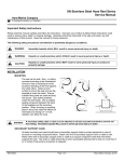
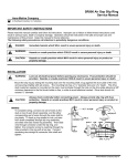
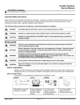
5F & 5FLR Series
Service Manual
AERO-MOTIVE COMPANY
A Woodhead Industries, Inc. Subsidiary
IMPORTANT SAFETY INSTRUCTIONS
Please read this manual carefully and follow its instructions. Improper use or failure to follow these instructions could
result in serious injury, death or property damage. Operators should be instructed in the safe and proper use and
maintenance of this product. Keep this manual for future reference.
The following safety precautions call attention to potentially dangerous conditions.
DANGER:
Immediate hazards which WILL result in severe personal injury or death.
WARNING:
Hazards or unsafe practices which COULD result in severe personal injury or death.
CAUTION:
Hazards or unsafe practices which MAY result in minor personal injury or product or
property damage.
NOTE: Instruct operators in the safe, proper use and maintenance. Keep this manual for future reference.
INSTALLATION
WARNING:
Failure to read, understand or follow these instructions could lead to hazards or unsafe
practices COULD result in severe personal injury or death.
CAUTION:
Operators need to be instructed on the safe, proper use and maintenance of this product.
Keep this manual for future references. Hazards or unsafe practices MAY result in minor
personal injury or product or property damage.
SWINGING MOUNTING
Hang retractor reel in desired location by clevis provided at
top. Reel should be suspended directly over work area (see
illustration), using an eyebolt or similar device with a breakstrength exceeding 6 times the combined weight of reel and
load it is supporting. Reel should be mounted in such a
manner as to minimize cable contact with cable guide. For
proper alignment, utilize three (3)-mounting holes at top of
reel. If shackle is removed to make connections, be sure
nut and cotter pin are properly replaced on shackle pin.
SECONDARY SUPPORT CHAIN
WARNING:
Attach a secondary safety cable, or chain, to all reels mounted overhead to prevent reel
from falling. Immediate hazards WILL result in severe personal injury or death.
A hole has been provided at side of housing to permit installation of a secondary support chain. All reels
mounted over head must have a secondary support chain to protect personnel in case of structure or
mounting component failure. Attach one end of secondary support chain or cable to secondary support
point (shackle) on reel. Attach other end of secondary support chain or cable to a support component
other than that which supports the retractor reel. Chain or cable should be as short as possible allowing
reel to drop no more than 6 to 12 inches if the primary connection is released. (See Illustration above). A
secondary support is offered as an accessory item.
SM111004D
Page 1 of 5
©Aero-Motive Company Dec-02
OPERATION
TOOL ATTACHMENT
WARNING:
Never pull cable to device to be retracted. Always lift object to hook. If the hook is
accidentally released when it is extended, it will snap back. Hazards or unsafe practices
which COULD result in severe personal injury or death.
Retractor reel is furnished with a tool clip. Attach tool complete with hose or cable and fittings. If, after
installation, it is determined the cable overhang is not sufficient; an overhang extension cable can be
used to extend overhang without reducing active travel. This is available as an optional item. To adjust
length of overhang, remove all tension, then pull down and position hook at desired height. Loosen cable
stop, then slide cable stop upward to roller guide and tighten. Move cable stop upward and lengthen
overhang of cable to reduce active travel distance. For every foot more of overhang adjusted on retractor
cable, there is an equal reduction in cable travel.
SPRING TENSIONING
WARNING:
Attach full load including all attachments before adjusting tension. Hazards or unsafe
practices COULD result in severe personal injury or death.
CAUTION:
When releasing tension, always do so slowly, and with wrench held firmly on shaft flats.
Gloves should be worn when using tension release lever. Hazards or unsafe practices
which MAY result in minor personal injury or product or property damage.
Tool including all attachments and connections must be in place before adjusting spring tension.
• If load exceeds spring tension, tool will drop, and tension must be increased.
• If tool is fully retracted but spring tension, seems excessive (rapid retraction), decrease tension.
Tension should always be
enough to retract tool and to keep
cable stop against guide.
To Increase Tension
Engage a wrench on flats on
mainspring shaft and turn in “+”
direction (as shown in diagram).
To Decrease Tension
Engage a wrench on flats on mainspring shaft. As tension release lever on opposite side of retractor is
gently pushed, shaft will unwind. Control unwinding with firmly held wrench.
After adjusting tension, pull cable to fullest extension to ensure full cable travel. If cable does not reach
full extension, some tension must be released. If proper tension and extension cannot be achieved,
another unit may be required. Please consult factory.
RATCHET LOCK (FOR 5FLR ONLY)
The ratchet lock can engage about every 6.5” of cable travel. Pull cable to desired location and let cable
retract slightly until lock engages, If it doesn’t engage, pullout a further, and then allow to retract. To
release lock, pull cable out at least 6 “. For constant tension, ratchet lock may be disengaged. Turn lock
release knob counter-clock wise while pulling cable in and out slightly to engage lock release lever.
SM111004D
Page 2 of 5
©Aero-Motive Company Dec-02
CABLE STOP ADJUSTMENT
NOTE: Moving the cable stop will reduce the active travel distance. If additional cable extension is required,
extension cable assemblies are offered as an accessory.
Cable stop can be moved up along the cable to attain the most desirable working height.
SERVICE
MAIN SPRING REPLACEMENT
CAUTION:
Remove all tension before removing mainspring. Hazards or unsafe practices MAY result
in minor personal injury or product or property damage.
WARNING:
Spring is dangerous. Always wear gloves. Before removing broken spring, weld coils
together at four (4) locations or wrap securely with wire. Hazards or unsafe practices
COULD result in severe personal injury or death.
Remove All tension from main spring (See Spring Tension
Adjustment). Remove cotter pin and then clevis. Next,
remove the retaining ring and the three (3) screws, also
plates and screws. Remove housing. Remove drum-cover
nuts and cover. Carefully remove mainspring from drum.
Hub may come off shaft with spring.
If so, replace hub into new spring while making sure hub engages spring coils. Replace spring in drum
while making sure the spring hook engages with drum outer hook. To reassemble, reverse the above
procedure. Be sure the hub engages the pin on the main shaft when reassembling.
CABLE REPLACEMENT
Whenever a cable shows signs of deterioration, it should be replaced with a new cable. Remove All
tension from main spring (See Spring Tension Adjustment). Remove clevis by removing the cotter pin.
Next, remove the retaining ring and the three (3) screws, also plates and screws. Remove housing.
Replace with new cable while threading it through guide first when reassembling.
RATCHET LOCK REPLACEMENT
Remove All tension from main spring (See Spring Tension Adjustment). Remove clevis by removing the
cotter pin. Next, remove the retaining ring and the three (3) screws, also plates and screws. Remove
retaining ring, washer, and spring lock, and retaining ring. The housing can now be removed. Remove
retaining ring and unclip spring, then remove ratchet lock. To reassemble, reverse the above procedure.
PARTS REPLACEMENT
CAUTION:
Always remove all spring tension (see “Spring Tension Adjustment”) before attempting to
disassemble internal parts. Always remove retractor reel from service. Hazards or unsafe
practices MAY result in minor personal injury or product or property damage.
NOTE: When ordering replacement parts, always include retractor reel model number and serial number.
All parts are replaceable in the field without special tools.
LUBRICATION
All bearings, springs, etc. are permanently lubricated at factory and should require no further lubrication.
MAINTENANCE & INSPECTION
Due to the design, this reel will require little maintenance other than a periodic check of the cable, safety
chain, and hanger for wear. All worn parts or cable should be removed from service and/or replaced at
once.
SM111004D
Page 3 of 5
©Aero-Motive Company Dec-02
REPLACEMENT PARTS
Ref. No.
1
2
3
4
5
6
7
8
9
10
11*
12
13
14
15
16
17
18
19
20*
21
SM111004D
Part Number
00580P0035
M62730003
01240P0010
00002P0202
1409900000
0980600000
0980500001
1402800000
1316000001
0982800000
1405800001
0981100226
1400500000
0981300000
00580P0045
0986200000
1361100000
00002P0200
1361300000
0983300000
0989300001
01146P0015
Qty.
1
2
1
2
1
1
1
2
1
1
1
1
2
2
1
1
2
1
1
1
1
Description
Ring; Retaining (.625)
Hanger; Mounting Bracket
Clevis
Screw; Machine
Spacer
Spacer; Cable Drum
Assembly; Drum (5FLR)
Assembly; Drum (5F)
Bearing; Main Shaft
Assembly; Main Shaft
Hub; Spring
Spring
Cover
Spacer
Ring; Retaining (.625)
Housing; Main
Lock; Spring Tension
Screw; #6-32 X ¼
Guide; Cable Outlet
Stop; Adjustable Cable
Cable (8ft.)
Clip; Tool
Page 4 of 5
©Aero-Motive Company Dec-02
0988800000
0985800000
25
00101P0017
26
00151P0015
Optional Items and Kits
KIT A
H16510008
KIT B
0985700001
0988200000
KIT C
0988300000
KIT D
4963800000
4965000009
4965000001
4965000002
4965000003
KIT E
4965000004
4965000005
4965000006
4965000007
4965000008
KIT F
0985800000
Misc.
H05040010
* Recommended Spare Parts
24
Aero-Motive Company
W
A Woodhead Industries Inc. Subsidiary
PO Box 2678
Kalamazoo, MI 49003-2678
USA
(269) 337 7700 / (800) 999 8559
FAX: (800) 333 6119
www.aeromotive.com
[email protected]
SM111004D
1
4
4
1
1
1
1
1
1
1
Assembly; STD Housing (5F)
Assembly; Housing w/Ratchet (5FLR)
Washer; Lock #6
Nut; Hex #6-32
Kit; Hanger ( Includes 2,3, & 4)
Complete cable ( Includes 19, 20, & 21)
Assembly; Shaft & Drum (5F) ( Includes 7-14)
Assembly: Shaft & Drum (5FLR) ( Includes 7-14)
Chain; Safety
Over Hang Cable (2 ft.)
Over Hang Cable (3 ft.)
Over Hang Cable (5 ft.)
Over Hang Cable (10 ft.)
Over Hang Cable (15 ft.)
Over Hang Cable (20 ft.)
Over Hang Cable (25 ft.)
Over Hang Cable (30 ft.)
Over Hang Cable (35 ft.)
Housing Assembly (includes all ratchet components)
Ratchet Spring Kit (From Kit F)
Woodhead Connectivity LTD.
W
A Woodhead Industries Inc. Subsidiary
Factory No. 9
Rassau Industrial Estate
Ebbw Vale Gwent NP23 5SD
United Kingdom
44-1495-356300
FAX: 44-1495-356301
[email protected]
Page 5 of 5
Woodhead Asia PTE LTD.
W
A Woodhead Industries Inc. Subsidiary
No. 4 Toh Tuck Link
Level 3 Mezzanine
Markono Logisitics Bldg.
Singapore 596226
65-6-261-6533
FAX: 65-6-261-3588
[email protected]
Woodhead Canada LTD.
W
A Woodhead Industries Inc. Subsidiary
1090 Brevik Place
Mississauga Ontario
L4W 3Y5 Canada
(905) 624-1079
FAX: (905) 624-9151
www.woodhead.ca
©Aero-Motive Company Dec-02