1
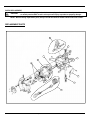
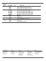
E, EA & EL Series Balancer
Service Manual
Aero-Motive® Balancers
IMPORTANT SAFETY INSTRUCTIONS
Please read this manual carefully and follow its instructions. Improper use or failure to follow these instructions could result
in serious injury, death or property damage. Operators should be instructed in the safe and proper use and maintenance of
this product. Keep this manual for future reference.
The following safety precautions call attention to potentially dangerous conditions.
DANGER:
Immediate hazards which WILL result in severe personal injury or death.
WARNING:
Hazards or unsafe practices which COULD result in severe personal injury or death.
CAUTION:
Hazards or unsafe practices which MAY result in minor personal injury or product or
property damage.
NOTE: Instruct operators in the safe, proper use and maintenance. Keep this manual for future reference.
INSTALLATION
WARNING:
Failure to read, understand or follow these instructions could lead to hazards or unsafe
practices COULD result in severe personal injury or death.
CAUTION:
Instruct operators in the safe, proper use and maintenance of this product. Hazards or
unsafe practices MAY result in minor personal injury or product or property damage.
MOUNTING
Hang balancer in the desired location by the shackle provided at the top. The balancer should be
suspended directly over work area using an eyebolt or similar device with a break strength exceeding 6
times the combined weight of the balancer and the load it is supporting. Balancer should be mounted in
such a manner as to minimize cable contact with the cable guide. For proper alignment, utilize the three
mounting holes at the top of balancer. If shackle is removed to make the connections, be sure that the nut
and cotter pin are properly replaced on the shackle pin.
SECONDARY SUPPORT CHAIN
WARNING:
A secondary safety cable or chain must be attached to all balancers mounted overhead to
prevent balancer from falling. Immediate hazards which WILL result in severe personal
injury or death.
A boss with a hole has been provided at the side of the housing to permit installation of a secondary support
chain. All balancers mounted over head should have a secondary support chain to protect personnel in case
of structure or mounting component failure. Attach one end of secondary support chain or cable to
secondary support point on balancer. Attach the other end of secondary support chain or cable to a support
component other than that which supports the balancer. The chain or cable should be as short as possible
allowing the balancer to drop no more than 6 to 12 inches if the primary connection is released. See
illustration below. Secondary chain is offered as an accessory item.
OPERATION
TOOL ATTACHMENT
WARNING:
SM113102F
Never pull cable to device to be retracted. Always lift object to hook. If the hook is
accidentally released when it is extended, it will snap back. Hazards or unsafe practices
which COULD result in severe personal injury or death.
Page 1 of 5
©Jul-05
When attaching tool to lower hook,
the tool should be lifted to the hook
rather than pulling empty hook out
against the reel tension. The drum
lock can be engaged to prevent
cable from retracting (see
illustration under “Tool
Replacement”). The retaining latch
on lower hook must be snapped
back in the closed position after tool
is attached.
SPRING TENSION ADJUSTMENT
NOTE: Attach full load including all attachments before adjusting tension. Only use adjusting nut to set
tension. If tension is removed well below the rated range of the balancer during spring adjustment,
automatic lock will engage. It will be necessary to apply more tension to release lock.
If weight of tool exceeds amount of existing tension of the balancer
mainspring, cable will descend. Spring tension can be adjusted by
turning adjustment nut clockwise to increase tension or
counterclockwise to decrease tension. If tension exceeds the load,
the tool will move upward. The adjustment is accomplished through
a worm gear. The 30:1 gear requires many turns to significantly
affect tension. If cable does not reach full extension, some tension
must be released. After adjusting tension, pull cable to fullest
extension to insure proper travel is achieved. If proper tension
cannot be achieved, consult factory.
AUTOMATIC LOCK
NOTE: If tension is removed well below the rated range of the Balancer during spring adjustment, the lock
will engage. It will be necessary to apply more tension to release the lock.
If a spring should break or lose tension for any reason, an automatic pin lock will engage to prevent drum
from turning. Lock will disengage when tension is applied to a new spring.
RATCHET LOCK (EL SERIES)
The ratchet/holding lock (separate from automatic lock) will function in
three positions per revolution, providing five to six inch increments. To
hold, pull cable down to desired height, halt, and let lock engage. To
disengage, simply pull cable down slightly, permitting the lock to
release. Cable will retract until end of travel, or until lock is re-engaged.
If ratchet lock is not required, it can be disengaged by moving the pin in
the housing downward and engaging hook-shaped lock arm over it.
CABLE STOP ADJUSTMENT
NOTE: Moving cable stop will reduce the active travel distance.
Relocating cable stop is not recommended. Rather, overhang cable assembly (see replacement parts,
Accessory “A”) is recommended.
SM113102F
Page 2 of 5
©Jul-05
SERVICE
TOOL REPLACEMENT
WARNING:
NEVER release drum lock unless full load is hung on balancer. If released with no load,
hook will retract rapidly, which causes hazards or unsafe practices and COULD result in
severe personal injury or death.
Pull tool down to the most convenient height and set manual drum lock
by lifting tab allowing pin to snap in (see illustration). This locks the
drum in place. The tool can now be removed and replaced. After
replacing tool, drum lock can be released by pulling outward on tab and
folding it back into its original position.
CABLE REPLACEMENT
NOTE: Whenever cable shows signs of deterioration, it should be replaced with new cable.
WARNING:
Never release the drum lock unless the full load is hung on the Balancer.
(If it is necessary to disassemble Balancer to change cable,
always remove all spring tension prior to disassembly (see Spring Tension Adjustment).
Hazards or unsafe practices COULD result in severe personal injury or death.
Whenever a cable shows signs of deterioration, it should be replaced
with a new cable. To replace cable, there is no need to disassemble
the balancer, just remove tension. Remove the bolts and cover. Pull
cable to its extreme lower limit, exposing threaded plug in drum as
shown in the illustration. Engage manual drum lock (as described in
“Tool Replacement”) and remove tool. Remove plug and old cable.
Insert new cable and replace plug and cover securely. Reattach tool
to lower hook and disengage drum lock.
MAIN SPRING REPLACEMENT
CAUTION:
Remove all tension before servicing. Hazards or unsafe practices MAY result in minor
personal injury or product or property damage.
Remove balancer from service, remove the
bolts, and cover assembly. Now remove bolts
and pull spring assembly from drum. Remove
bearing from old spring housing and replace it
in the new one, or replace bearing with a new
bearing. Reassemble in reverse order and
readjust tension as described in Spring
Tension Adjustment. To align springs with
spring hub, it may be necessary to rotate
spring assembly back and forth slightly as
spring assembly is pushed back onto shaft.
MAINTENANCE, INSPECTION & LUBRICATION
Periodic inspection of the cable and lower hook and upper swivel mount assembly is strongly recommended
for safe operation. Bearings and guide rollers should also be inspected periodically to insure efficient
operation. All bearings, springs, etc. are permanently lubricated at the factory and should require no further
lubrication.
SM113102F
Page 3 of 5
©Jul-05
PARTS REPLACEMENT
CAUTION:
Always remove all spring tension before attempting to disassemble internal parts. Hazards
or unsafe practices MAY result in minor personal injury or product or property damage.
NOTE: When ordering replacement parts, always include the balancer model number and serial number.
REPLACEMENT PARTS
SM113102F
Page 4 of 5
©Jul-05
Reference
Number
1
2
3
4
5
6
7
8
9
Part Number
CBAEB7
CBAEBL
CBAET7
CBAETL
4191000000
3167200040
4191200000
3165900020
3165900030
3165900040
DRME7
SHFE
DLKE
UHKEB
UHKES
CBGE
WRME
DSAEA
Qty.
1
1
1
1
1
1
1
1
1
1
1
1
1
1
1
1
1
1
Description
Cable Assembly; Bullard Type (E, EA, Series)
Cable Assembly; Bullard Type (EL Series)
Cable Assembly; Tool Clip Type (E, EA, Series)
Cable Assembly; Tool Clip Type (EL, Series)
Mainspring Assembly with Bearing (25EL)
Mainspring Assembly with Bearing (40EL)
Mainspring Assembly with Bearing (10E & 10EA)
Mainspring Assembly with Bearing (20E & 20EA)
Mainspring Assembly with Bearing (30E & 30EA)
Mainspring Assembly with Bearing (40E & 40EA)
Drum Kit
Shaft Kit
Drum Lock Kit
Shackle Assembly Kit: Bullard Type
Shackle Assembly Kit: Shackle Type
Cable Guide Assembly
Worm Gear Kit
Drop Stop Actuator Kit for EA
United States/Mexico
Canada
Europe
Asia
Japan
Woodhead L.P.
3411 Woodhead Drive.
Northbrook, IL 60062
800 999 8559
FAX: 800 333-6119
www. Woodhead.com
Woodhead Canada Limited
1090 Brevik Place
Mississauga Ontario L4W 3Y5
905 624-6518
FAX: 905 624-9151
www. Woodhead.ca
Woodhea Connectivity Ltd.
Factory No. 9
Rassau Industrial Estate
Ebbw Vale, Gwent, Wales
United Kingdom NP3 5SD
+44 1495 356 300
FAX: +44 1495 356 301
[email protected]
Woodhead Asia Pte. Ltd.
No.4, Toh Tuck Link,
Level 3, Mezzanine
Markono Logistics Bldg.
SINGAPORE 596 226
+65 6261 6533
FAX: +65 6261 3588
[email protected]
Woodhead Japan Corp.
Unit 2-1, Kawashima No. 3 Bldg.
30-2 Imaike-Minami, Chikusa-ku
Nagoya, Japan 464-0851
+81 52 745 7621
FAX: +81 52 745 7622
SM113102F
Page 5 of 5
©Jul-05