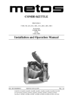
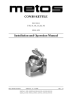
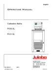
1
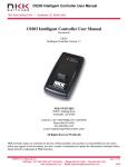
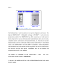
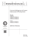
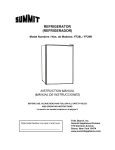
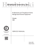
Hoshizaki
Hoshizaki America, Inc.
Commercial Refrigerators & Freezers
Models
SafeTemp
®
“A Superior Degree
of Reliability”
SERVICE MANUAL
www.hoshizaki.com
Number: 73096
Issued: 10-9-2000
Revised: 3-7-2007
IMPORTANT
Only qualified service technicians should attempt to service or maintain this
unit. No such service or maintenance should be undertaken until the technician
has thoroughly read this Service Manual.
HOSHIZAKI provides this manual primarily to assist qualified service technicians in the
service and maintenance of the unit.
Should the reader have any questions or concerns which have not been satisfactorily
addressed, please call, write or send an e-mail message to the HOSHIZAKI Technical
Support Department for assistance.
HOSHIZAKI AMERICA, INC.
618 Highway 74 South
Peachtree City, GA 30269
Attn: HOSHIZAKI Technical Support Department
Phone: 1-800-233-1940 Technical Service
(770) 487-2331
Fax: 1-800-843-1056
(770) 487-3360
E-mail: [email protected]
Web Site: www.hoshizaki.com
NOTE: To expedite assistance, all correspondence/communication MUST include the following information:
• Model Number
• Serial Number
• Complete and detailed explanation of the problem
Please review this manual. It should be read carefully before the unit is serviced or
maintenance operations are performed. Only qualified service technicians should service
and maintain the unit. This manual should be made available to the technician prior to
service or maintenance.
CONTENTS
I. Specifications....................................................................................................................... 5
A. Nameplate Ratings........................................................................................................ 5
B. Dimensions.................................................................................................................... 5
1. Notes for All Units..................................................................................................... 5
2. RH1-AAC(-HD), FH1-AAC(-HD)............................................................................... 6
3. RH2-AAC(-HD), FH2-AAC(-HD)............................................................................... 7
4. RH3-AAC(-HD)......................................................................................................... 8
II. General Information............................................................................................................ 9
A. Sequence of Operation and Timing Charts.................................................................... 9
1. Refrigerator ............................................................................................................. 9
2. Freezer................................................................................................................... 11
B. Control Module............................................................................................................. 13
1. Settings and Adjustments....................................................................................... 13
2. Service Menu......................................................................................................... 14
C. Thermistors.................................................................................................................. 16
1. Cabinet Thermistor (SEN1: white and black leads)................................................ 16
2. Defrost Thermistor (SEN2: black and red leads) ................................................... 16
3. Thermistor Check Procedure.................................................................................. 16
D. Compressor Protector.................................................................................................. 17
E. Safety Devices............................................................................................................. 17
1. Pressure Switch...................................................................................................... 17
2. Defrost Protection................................................................................................... 17
F. Perimeter Frame Heater............................................................................................... 17
III. Service Diagnosis............................................................................................................ 18
A. Diagnosis Chart........................................................................................................... 18
IV. Removal and Replacement of Components.................................................................... 21
A. Service for Refrigerant Lines....................................................................................... 21
1. Refrigerant Recovery.............................................................................................. 21
2. Brazing................................................................................................................... 21
3. Evacuation and Recharge [R-134a, R-404A]......................................................... 22
B. Removal and Replacement of Compressor................................................................. 23
C. Removal and Replacement of Expansion Valve.......................................................... 24
D. Removal and Replacement of Evaporator................................................................... 25
E. Removal and Replacement of Door Gasket................................................................. 25
F. Removal and Replacement of Door Closure Spring..................................................... 26
G. Door Re-Hinging.......................................................................................................... 27
H. Removal and Replacement of Control Module............................................................ 28
I. Removal and Replacement of Thermistors................................................................... 29
V. Cleaning Instructions........................................................................................................ 32
VI. Wiring Diagrams.............................................................................................................. 33
A. RH1-AAC(-HD)............................................................................................................. 33
B. RH2-AAC(-HD)............................................................................................................. 34
C. RH3-AAC(-HD)............................................................................................................. 35
D1. FH1-AAC(-HD) (auxiliary code P-7 and earlier)......................................................... 36
D2. FH1-AAC(-HD) (auxiliary code P-8 and later)............................................................ 37
E1. FH2-AAC(-HD) (auxiliary code P-5 and earlier)......................................................... 38
E2. FH2-AAC(-HD) (auxiliary code P-6 and later)............................................................ 39
I. Specifications
A. Nameplate Ratings
RH1-AAC / RH1-AAC-HD
FH1-AAC / FH1-AAC-HD
RH2-AAC / RH2-AAC-HD
FH2-AAC / FH2-AAC-HD
RH3-AAC / RH3-AAC-HD
RH1-AAC-W
AC Supply Voltage
115/60/1
115/60/1
115/60/1
115/60/1
115/60/1
115/60/1
Amperes
5.0
12
7.0
15.5
12.0
7.0
Design Pressure
(PSIG)
HI
LO
240
120
475
250
240
120
450
250
250
120
450
200
Refrigerant and
Refrigerant Charge
R-404A
R-134a
9.3 OZ
15.2 OZ
11.6 OZ
20.1 OZ
20.6 OZ
12.2 OZ
B. Dimensions
1. Notes for All Units
1) Units shipped with 4" casters
2) Optional legs have 25.4 mm (1 in.) height adjustment
Door Opening
RH1-AAC / FH1-AAC
RH1-AAC-HD / FH1-AAC-HD
RH2-AAC / FH2-AAC
RH2-AAC-HD / FH2-AAC-HD
RH3-AAC
RH3-AAC-HD
Width
mm (in.)
554.8 (21.8)
554.8 (21.8)
554.8 (21.8)
554.8 (21.8)
554.8 (21.8)
554.8 (21.8)
Height
mm (in.)
1507 (59.3)
681.7 (26.8)
1507 (59.3)
681.7 (26.8)
1507 (59.3)
681.7 (26.8)
Total
Refrigerated
Volume ft3
Total Shelf
Space ft2
22.3
22.3
48.3
48.3
73.7
73.7
11.5
25.9
40.3
See the nameplate for electrical and refrigeration specifications. The nameplate is
located on the right side wall of the cabinet interior.
Note: We reserve the right to make changes in specifications and design without prior
notice.
2. RH1-AAC(-HD), FH1-AAC(-HD)
mm (in.)
* Shown with optional 6" legs; 4" casters are standard
3. RH2-AAC(-HD), FH2-AAC(-HD)
mm (in.)
* Shown with optional 6" legs; 4" casters are standard
4. RH3-AAC(-HD)
mm (in.)
* Shown with optional 6" legs; 4" casters are standard
II. General Information
A. Sequence of Operation and Timing Charts
1. Refrigerator
a) Sequence of Operation
POWER ON
1. Frame heaters on
2. Evaporator fan on
Cycle On (Cut-on
temperature reached)
[Minimum 2.0 minutes]
1. Compressor on
2. Condenser fan on
2.0 minute delay
1. Compressor start-up
2. Condenser fan start-up
Cycle Off (Cut-out
temperature reached)
[Minimum 2.0 minutes]
1. Compressor off
2. Condenser fan off
If evaporator temperature
reaches 13°F, unit initiates
defrost. Defrost initiation for
RH1-AAC-W is 7°F.
1. Compressor off
2. Condenser fan off
(Note: Evaporator fan is on.)
Evaporator temperature
reaches 40°F, defrost
terminated
1. Compressor on
2. Condenser fan on
Normal cycling continues
Note: The start circuit of the compressor is timed such that at power-up and during any
compressor off time, there will be at least a 2 minute delay before the compressor
will start. The compressor has a 2 minute minimum run time during every run
cycle. The only exception is when the overload activates and deactivates.
b) Timing Chart
For Refrigerator
10
2. Freezer
a) Sequence of Operation
POWER ON
Defrost End
Defrost thermistor
reaches 100°F;
Defrost heater off
Initiate Defrost
1. Compressor off
2. Evaporator fan off
3. Condenser fan off
4. Defrost heater on
5. "dEF" displayed
6. Frame heaters on
Evaporator temperature
drops to 70°F
1. Evaporator fan on
Cycle On (Cut-on
temperature reached)
[Minimum 2.0 minutes]
1. Compressor on
2. Condenser fan on
Cycle Off (Cut-out
temperature reached)
[Minimum 2.0 minutes]
1. Compressor off
2. Condenser fan off
Defrost Start
Preprogrammed time interval
1. Compressor off
2. Evaporator fan off
3. Condenser fan off
4. Defrost heater on
5. "dEF" displayed
Normal cycling continues
Five minutes after
defrost heater off
1. Compressor on
2. Condenser fan on
3. "rEC" displayed
Defrost End
Defrost thermistor
reaches 100°F;
Defrost heater off
Cabinet thermistor drops to
15°F above setpoint.
1. "rEC" no longer displayed;
cabinet temp. displayed
Cabinet thermistor drops
to 15°F above setpoint.
1. "rEC" no longer
displayed; cabinet temp.
displayed
Five minutes after
defrost heater off
1. Compressor on
2. Condenser fan on
3. "rEC" displayed
Evaporator temperature
drops to 70°F
1. Evaporator fan on
Note: For freezers, defrost will be initiated at power-up. To bypass initial defrost, press
and hold the up arrow button on the control module while turning on the toggle
switch. The display should read a temperature. There will be at least a 2 minute
delay before the compressor will start even if the initial defrost cycle is bypassed.
The compressor has a 2 minute minimum run time during every run cycle. The
only exception is when the overload activates and deactivates.
11
b) Timing Chart
For Freezer
12
B. Control Module
The control module for -AAC models is located on the face of the refrigeration circuit,
behind the front panel. To open the front panel, swing the bottom of the panel up and allow
the panel hinges to catch securely on the side panel frames in the locked position; the
control module can then be accessed.
Front Panel
Control Module
Door
1. Settings and Adjustments.
a) Current Temperature Display
• The cabinet temperature is displayed on the control module. The cabinet temperature is
displayed in °F only.
• The cabinet temperature is updated every 2 seconds.
• When the fan, compressor and defrost are initiated, the corresponding indicator lights
will switch on.
b) Temperature Setpoint
The temperature setpoint is the temperature at which the compressor comes on. For
refrigerators, the temperature differential for the compressor to turn off is 5°F below the
setpoint. For freezers, the temperature differential for the compressor to turn off is 6°F
below the setpoint, If necessary, adjust the setpoint temperature as follows:
1) Press "SET." The display reads: SP1
2) Press "SET." The display reads: Current Setpoint
3) Use the up/down arrows to change the setpoint. For refrigerators, the cabinet
temperature is adjustable between 37°F and 55°F. The factory default is 39°F. For
freezers, the cabinet temperature is adjustable between -10°F and 28°F. The factory
default is -1°F for the FH1-AAC(-HD) and 0°F for the FH2-AAC(-HD).
4) Press "SET" to save. If no button is pressed in 15 seconds, the display will return to
normal, and the setpoint will remain unchanged.
13
c) Defrost
(1) For Refrigerators
This unit uses an off-cycle defrost. A thermistor in the evaporator coil determines the
need for a defrost. When the sensor reaches the initiation setpoint, the unit enters
defrost. When the unit reaches the termination setpoint, the unit ends defrost. The offcycle defrost requires no programming; it automatically initiates and terminates.
(2) For Freezers
This unit is preset at the factory to defrost 6 times per day for general conditions. Please
note that the defrost is a heated defrost, and therefore will have a tendency to raise
the cabinet temperature. Cabinet temperature is not displayed during defrost; "dEF"
is displayed in its place. Five minutes after defrost ends, the display changes to "rEC"
(recovery period). Once the cabinet thermistor drops to 15°F above the setpoint, the
display reverts back to cabinet temperature.
2. Service Menu
The menu may be used to view settings and the defrost thermistor temperature and to
make adjustments to the defrost frequency.
To access this menu, press and hold the "°F" and down arrow buttons. Once released,
you will have access to the menu. To advance to the next display press "°F". To store
changed settings, you may either advance through all menus by pressing "°F" until
you return to cabinet temperature, or you may press "SET". Either procedure will store
changed settings and return to the cabinet temperature.
WARNING
This unit has been factory tested with the default settings listed. If a value
is changed from the default, field problems may result. If a value has been
changed from the default and you need to change it back, use the up or down
arrow buttons.
Display
Indication
dIF
Next display is cabinet differential setting
-5
Indicates that the cabinet differential is set to -5°F.
HI
Next display is the maximum allowable setpoint (from the setpoint
menu).
55
Indicates that the maximum allowable setpoint is 55°F.
LO
Next display is the minimum allowable setpoint (from the setpoint
menu).
37
Indicates that the minimum allowable setpoint is 37°F.
CAL
0
Next display is for calibration of the thermistor.
Do not adjust, unless replacing thermistors.
14
Default
Refrigerator
Freezer
-5°F
-6°F
55°F
28°F
37°F
-10°F
NA
NA
Display
dEF
In1
(Refrigerator
Only)
13
dEF
Indication
Next display after these is the defrost initiation
temperature.
Default
Refrigerator
Freezer
13°F
(7°F for
RH1-AAC-W)
NA
40°F
NA
NA
Every 4
hours
NA
60 min.
NA
100°F
2.0 min.
2.0 min.
NA
70°F
NA
NA
Indicates that the setpoint for defrost initiation is 13°F.
Next display after these is the defrost termination temperature.
End
(Refrigerator
Only)
40
dEF
Indicates that the setpoint for defrost termination is 40°F.
Next display after these is the number of hours between defrosts.
Int
(Freezer Only)
4
Indicates that there will be one defrost every 4 hours.
WARNING: This value should be adjusted only after consulting with
the factory.
dEF
Next display after these is the maximum allowable time for a defrost.
The freezer’s target is to terminate before this value is reached. This
value is a safety.
dUr
(Freezer Only)
60
dEF
HI
(Freezer Only)
Indicates that the maximum time for a defrost is 60 minutes.
WARNING: This value should never be changed from the default.
Next display after these is the defrost termination temperature. The
freezer’s target is to terminate at this value.
100
Indicates that the defrost termination temperature is 100°F.
SHo
Next display after these is the short cycle timer. The short cycle time
is the minimum time the compressor must remain off in an off cycle
or on in an on cycle.
CyC
2
FAn
HI
(Freezer Only)
Indicates that the short cycle timer is set to 2.0 minutes.
Next display after these is the re-initiation temperature of the
evaporator fan after a defrost.
0
Indicates that the evaporator fan re-initiation temperature after a
defrost is 70°F.
COI
Next display after these is the defrost sensor temperature.
SEn
20
Indicates that the temperature of the defrost sensor is 20°F.
15
C. Thermistors
Thermistors (semiconductors) are used for cabinet temperature control and defrost
termination. The resistance varies depending on temperature. No adjustment is required.
If necessary, check for resistance between thermistor leads and visually check the
thermistor mounting.
1. Cabinet Thermistor (SEN1: white and black leads)
This temperature reading can be identified by looking at the temperature shown on the
display. However, in some cases the display may be reading "dEF". In this case turn the
unit to the "OFF" position. Next press the up arrow button while turning the unit "ON" with
the toggle switch. This will by-pass the initial defrost cycle and allows the display to show
the cabinet thermistor reading. This temperature should correspond closely with the
actual cabinet temperature.
2. Defrost Thermistor (SEN2: black and red leads)
This temperature reading can be found by entering the service menu. To access this
menu, press and hold the "°F" and down arrow buttons. Once released, "dIF" is displayed
and you have access to the menu. To advance to the next display, press the "°F" button.
Press "°F" until "SEn" is displayed. Press "°F" one more time and this reading should be
the evaporator coil temperature.
Note: This thermistor is mounted in the evaporator; therefore, when the machine is in
the freeze cycle you will see temperatures that correspond to actual evaporator
temperature.
3. Thermistor Check Procedure
1) Unplug the unit from the electrical outlet and disconnect thermistor leads on the control
module.
2) Remove the thermistor.
3) Immerse the thermistor sensor portion in a glass containing ice water for 2 or 3 minutes.
4) Check for a resistance between thermistor leads. Replace the thermistor if it exceeds
the normal reading. See "IV.I. Removal and Replacement of Thermistors."
Temperature
Resistance Ω
°F
°C
0
-17.8
704
10
-12.2
713
32
0.0
812
50
10.0
880
70
21.1
961
90
32.2
1,046
16
D. Compressor Protector
When a combined temperature/amperage value is above the limit specified by the
compressor manufacturer, a protector will operate independently, turning off the
compressor. The compressor will restart when this protector has reset.
Note:
1. Compressor protector resets automatically.
2. If the condenser fan is operating and the compressor is off, it is likely that the
protector has operated.
E. Safety Devices
1. Pressure Switch
When pressure on the high-side of the refrigeration circuit is detected to be above
a preset limit, a pressure switch will activate causing power to be interrupted to the
compressor relay. This power interruption will shut down the compressor. The pressure
switch will reset automatically. When the pressure switch resets, power will be resupplied
to the compressor. See "VI. Wiring Diagrams" for preset values.
2. Defrost Protection
For freezers, primary defrost termination is controlled by the defrost thermistor. However,
two additional safeties are also present:
1) Time Termination - 1 hour maximum
2) Safety Defrost Thermostat - In-line with the heaters and independent of the control
module.
F. Perimeter Frame Heater
This unit is equipped with a perimeter frame heater. This prevents the formation of
condensate on the front frame of the unit under high humidity conditions. If operating the
unit under conditions where condensate will not form, these heaters may be turned off
using the switch on the control box.
17
III. Service Diagnosis
A. Diagnosis Chart
Problem
Possible Cause
[1] Compressor will
not start—no
current draw.
a) Power Supply
Remedy
1. "OFF" position.
1. Move to "ON" position.
2. Loose connection.
2. Tighten.
3. Failure.
3. Call electrician.
b) Cord and Plug
1. Defective.
1. Replace.
c) Ground Fault Circuit
Interrupter
1. Tripped.
1. Check and reset.
2. Defective.
2. Replace.
d) Transformer
1. Open coil winding.
1. Check continuity and
replace.
e) Wiring to Control Module 1. Loose connection.
2. Check continuity and
replace.
f) High Pressure Switch
1. Bad contacts.
1. Check continuity and
replace.
g) Thermistor
1. Defective.
1. See "II.C. Thermistors."
Check and replace.
h) Control Module
1. Defective.
1. Replace control module.
i) Compressor Overload
1. Defective (contacts
open).
1. Replace.
j) Compressor
1. Open windings.
1. Check continuity and
replace.
k) Compressor Relay
[2] Compressor will
not run—draws
current and trips
on overload.
[3] Compressor runs
intermittently and
trips on overload.
[4] Cabinet temperature
too high; compressor
will not start.
1. Tighten.
2. Faulty.
1. Bad contacts.
1. Replace.
2. Open coil winding.
2. Check and replace.
a) Voltage
1. Too low.
1. Call electrician.
b) Start Relay
1. Bad contacts.
1. Replace.
2. Open coil windings.
2. Replace.
c) Compressor
1. Locked rotor.
1. Replace.
d) Start Capacitor
1. Defective.
1. Check and replace.
a) Voltage
1. Too low.
1. Call electrician.
2. Too high.
2. Call electrician.
b) Condenser Filter
1. Clogged.
1. Clean filter.
c) Refrigerant Line or
Component
1. Plugged or restricted.
1. Clean and replace drier.
d) Condenser Fan Motor
1. Failed
1. Replace.
e) Refrigerant
1. Overcharged.
1. Evacuate and recharge.
2. Non-condensibles in
system.
2. Evacuate and recharge.
f) Location of Unit
1. Restricted air flow to
condenser.
1. Move unit or increase
ventilation.
a) Thermistor
1. Defective.
1. See "II.C. Thermistors."
Check and replace.
b) Compressor Relay
1. Defective.
1. Check and replace.
c) Control Module
1. Defective.
1. Replace.
18
Problem
Possible Cause
[5] Cabinet temperature
too high.
a) Setpoint
1. Incorrect.
Remedy
1. Correct setpoint. See
"II.B.1.b) Temperature
Setpoint."
b) Door
1. Not sealing, or open for
long intervals.
1. Check for sealing, check for
door open at time of warm
cabinet temperature.
c) Defrost
1. Not enough defrosts
occurring per day.
Operation in humid
conditions.
1. See "II.B.1.c) Defrost."
d) Refrigerant
1. Leak.
1. Repair leak and recharge.
e) Fan Motor
1. Defective.
1. Check and replace.
f) Air Filter
1. Clogged.
1. Clean.
g) Condenser
1. Dirty.
1. Clean.
h) Thermistor
1. Defective.
1. See "II.C. Thermistors."
Check and replace.
i) Control Module
1. Defective.
1. Replace.
[6] Cabinet temperature
a) Control Module
display indicator does
not illuminate properly.
1. Defective.
1. Replace.
[7] Cabinet temperature
too low.
a) Thermistor
1. Defective.
1. See "II.C. Thermistors."
Check and replace.
b) Compressor Relay
1. Defective; contacts
welded.
1. Replace.
c) Control Module
1. Defective.
1. Replace.
1. Defective.
1. See "II.C. Thermistors."
Check and replace.
b) Defrost
1. Not enough defrosts
occurring per day.
Operation in humid
conditions.
1. See "II.B.1.c) Defrost."
c) Defrost Heaters
(freezers only)
1. Defective.
1. Replace heaters.
d) Safety Defrost
Thermostat
(freezers only)
1. Defective, turning off
heaters prematurely, or
fused open.
1. Replace safety defrost
thermostat.
a) Defrost Thermistor
1. Defective.
1. Replace.
b) Control Module.
1. Defective.
1. Replace.
c) Defrost
1. Not enough defrosts
occurring per day.
Operation in humid
conditions.
1. See "II.B.1.c) Defrost."
d) Defrost Heaters.
(freezers only)
1. Defective.
1. Replace heaters.
e) Safety Defrost
Thermostat
(freezers only)
1. Defective, turning off
heaters prematurely, or
fused open.
1. Replace safety defrost
thermostat.
[8] Evaporator does
a) Defrost Thermistor
not defrost completely.
[9] Defrost cycle
lasts too long.
19
Problem
Possible Cause
[10] Condensate
water overflow.
a) Cabinet Contents
1. Loading of large
1. Cover product with plastic
volumes of warm, moist,
wrap.
uncovered product.
b) Location of Unit
1. Unit located near high
1. Relocate.
humidity source such as
fryer, steamer, etc.
c) Seals
1. Poor sealing around
1. Adjust or replace.
evaporator, door gaskets.
d) Environment
1. Extreme environment
and door-opening
conditions.
1. Adjust conditions.
a) Fasteners
1. Loose fasteners allow
vibration of part.
1. Tighten fasteners.
b) Compressor
1. Problem with mount.
1. Properly mount compressor.
Replace any missing
grommets.
2. Floodback to
compressor.
2. Check for signs of floodback
to compressor. Evacuate
and recharge if necessary.
3. Defective.
3. Replace.
1. Fan blade loose.
1. Adjust and tighten.
2. Defective motor.
2. Replace.
1. Chattering.
1. Replace.
[11] Abnormal Noise
c) Fan
d) Relay
Remedy
20
IV. Removal and Replacement of Components
IMPORTANT
1. Ensure all components, fasteners and thumbscrews are securely in place
after the equipment is serviced.
2. The Polyol Ester (POE) oils used in R-134a and R-404A units can absorb
moisture quickly. Therefore it is important to prevent moisture from entering
the system when replacing or servicing parts.
3. Always install a new drier every time the sealed refrigeration system is
opened. Do not replace the drier until after all other repair or replacement
has been made.
4. Do not leave the system open for longer than 15 minutes when replacing or
servicing parts.
A. Service for Refrigerant Lines
WARNING
Do not use R-134a or R-404A as a mixture with pressurized air for leak
testing. Refrigerant leaks can be detected by charging the unit with a trace
of refrigerant, raising the pressure with nitrogen and using an electronic leak
detector.
1. Refrigerant Recovery
The unit is provided with refrigerant access valves. Using proper refrigerant practices
recover the refrigerant from the access valves and store it in an approved container. Do
not discharge the refrigerant into the atmosphere.
2. Brazing
WARNING
1. Refrigerants R-134a and R-404A themselves are not flammable at
atmospheric pressure and temperatures up to 212°F (100°C) for R-134a and
176°F (80°C) for R-404A.
2. Refrigerants R-134a and R-404A themselves are not explosive or poisonous.
However, when exposed to high temperatures (open flames) R-134a and
R-404A can be decomposed to form hydrofluoric acid and carbonyl fluoride
both of which are hazardous.
3. Always recover the refrigerant and store it in an approved container. Do not
discharge the refrigerant into the atmosphere.
4. Do not use silver alloy or copper alloy containing arsenic.
5. Do not use R-134a or R-404A as a mixture with pressurized air for leak
testing. Refrigerant leaks can be detected by charging the unit with a trace
of refrigerant, raising the pressure with nitrogen and using an electronic leak
detector.
21
1) Always install a new drier every time the sealed refrigeration system is opened. Do not
replace the drier until after all other repair or replacement has been made. Install the
new drier with the arrow on the drier in the direction of the refrigerant flow.
2) Braze all fittings while purging with nitrogen gas flowing at a pressure of 3 to 4 PSIG.
3) Check for leaks using nitrogen gas (140 PSIG) and soap bubbles. Do not use R-134a
or R-404A as a mixture with pressurized air for leak testing. Refrigerant leaks can
be detected by raising the pressure with nitrogen and a trace of refrigerant, using an
electronic leak detector.
Note: Because the pipes in the evaporator case are specially coated to resist corrosion,
it is important to make connections outside the evaporator case when possible. If
it is necessary to braze inside the evaporator case, use sandpaper to remove the
coating from the brazing connections before unbrazing the components.
3. Evacuation and Recharge [R-134a, R-404A]
1) Attach a vacuum pump to the system. Be sure the charging hoses are connected to
both high and low-side lines.
IMPORTANT
The vacuum pump may be the same as those for current refrigerants. However,
the rubber hose and gauge manifold to be used for evacuation and refrigerant
charge should be exclusively for POE oils.
2) Turn on the vacuum pump. Never allow the oil in the vacuum pump to flow backward.
3) Allow the vacuum pump to pull down to a 29.9" Hg vacuum. Evacuating period depends
on pump capacity.
4) Close the low-side valve and high-side valve on the service manifold.
5) Disconnect the vacuum pump, and attach a refrigerant service cylinder to the highside line. Remember to loosen the connection and purge the air from the hose. See
the nameplate for the required refrigerant charge. Hoshizaki recommends only virgin
refrigerant or reclaimed refrigerant which meets ARI Standard No. 700-88 be used.
6) A liquid charge is recommended for charging an R-134a or R-404A system. Invert the
service cylinder and place it on scales. Open the high-side, service manifold valve.
7) Allow the system to charge with liquid until the proper charge weight is met.
8) If necessary, add any remaining charge to the system through the low-side. Use a
throttling valve or liquid dispensing device to add the remaining liquid charge through
the low-side access port with the unit running.
9) Close the two refrigerant access valves and disconnect the hoses and service manifold.
10) Cap the access valves to prevent a possible leak.
22
B. Removal and Replacement of Compressor
IMPORTANT
Always install a new drier every time the sealed refrigeration system is opened.
Do not replace the drier until after all other repair or replacement has been
made. Install the new drier with the arrow on the drier in the direction of the
refrigerant flow.
Note: When replacing a compressor with a defective winding, be sure to install the
new start capacitor and start relay supplied with the replacement compressor.
Due to the ability of the POE oil in the compressor to absorb moisture quickly,
the compressor must not be opened more than 15 minutes for replacement or
service. Do not mix lubricants of different compressors even if both are charged
with R-134a or R-404A, except when they use the same lubricant.
1) Unplug the unit from the electrical outlet.
2) Remove the panels.
3) Recover the refrigerant and store it in an approved container.
4) Remove the terminal cover on the compressor, and disconnect the compressor wiring.
5) Remove the hold-down bolts, washers, rubber grommets and sleeves.
6) Remove the discharge and suction pipes.
7) Remove the compressor. Unpack the new compressor package.
8) Attach the rubber grommets of the prior compressor.
9) Place the compressor in position and secure it using the bolts and washers.
10) Remove the drier, then place the new drier in position.
11) Remove plugs from the suction, discharge and process pipes.
12) Braze all fittings while purging with nitrogen gas flowing at a pressure of 3 to 4 PSIG.
13) Check for leaks using nitrogen gas (140 PSIG) and soap bubbles.
14) Evacuate the system, and charge it with refrigerant. See the nameplate for the required
refrigerant charge.
15) Connect the terminals and replace the terminal cover in its correct position.
16) Replace the panels in their correct positions.
17) Plug the unit back in.
23
C. Removal and Replacement of Expansion Valve
IMPORTANT
Sometimes moisture in the refrigeration circuit exceeds the drier capacity and
freezes up at the expansion valve. Always install a new drier every time the
sealed refrigeration system is opened. Do not replace the drier until after all
other repair or replacement has been made. Install the new drier with the arrow
on the drier in the direction of the refrigerant flow.
1) Unplug the unit from the electrical outlet.
2) Remove the panels.
3) Recover the refrigerant and store it in an approved container.
4) Remove the insulation and the expansion valve bulb on the suction line.
5) Remove the expansion valve cover and disconnect the expansion valve. Place the new
expansion valve in position.
6) Remove the drier, then place the new drier in position.
7) Braze all fittings while purging with nitrogen gas flowing at a pressure of 3 to 4 PSIG.
WARNING
Always protect the valve body by using a damp cloth to prevent the valve from
overheating. Do not braze with the valve body exceeding 250°F (121°C).
8) Check for leaks using nitrogen gas (140 PSIG) and soap bubbles.
9) Evacuate the system, and charge it with refrigerant. See the nameplate for the required
refrigerant charge.
10) Attach the expansion valve bulb to the suction line in the same location as the previous
bulb. The bulb should be at the 12 o'clock position on the tube. Be sure to secure the
bulb with the clamp and holder and to insulate it.
11) Place the expansion valve cover in position.
12) Replace the panels in their correct positions.
13) Plug the unit back in.
24
D. Removal and Replacement of Evaporator
IMPORTANT
Always install a new drier every time the sealed refrigeration system is opened.
Do not replace the drier until after all other repair or replacement has been
made. Install the new drier with the arrow on the drier in the direction of the
refrigerant flow.
1) Unplug the unit from the electrical outlet.
2) Remove the panels and the top cover over the evaporator.
3) Recover the refrigerant and store it in an approved container.
4) Remove the insulation tubing, and disconnect the evaporator inlet and outlet tubing.
Elevate the evaporator to avoid overheating the evaporator housing.
5) Place the new evaporator in position.
6) Remove the drier, then place the new drier in position.
7) Check for leaks using nitrogen gas (140 PSIG) and soap bubbles.
8) Evacuate the system, and charge it with refrigerant. See the nameplate for the required
refrigerant charge.
9) Replace the removed parts in the reverse order of which they were removed.
10) Replace the top cover and the panels in their correct positions.
11) Plug the unit back in.
E. Removal and Replacement of Door Gasket
CAUTION
In order to get a proper gasket fit, it is important not to stretch gasket material
during assembly.
1) Remove old gasket by pulling it directly out of the vinyl gasket retainer.
2) Thoroughly clean the gasket area with mild soap and water prior to installing the new
gasket.
3) The new gasket should be installed by assembling it at the corners first, then working
toward the center at the top, bottom and sides.
4) The arrow-shaped portion of the gasket should be firmly seated in the retainer
groove for proper assembly. This can be checked by lifting the edge of the gasket and
observing the engagement.
25
F. Removal and Replacement of Door Closure Spring
CAUTION
Wear eye protection and use caution when removing the tension screw
(step 3).
1) Open the front panel assembly to gain access to the upper hinge brackets.
2) Remove the bushing cover from the top of the spring cartridge assembly.
Pivot Pin
Hinge Stop Pin
Hinge Washer
Hinge Bracket
Bushing Cover
Tension Screw
Spring Cartridge
Spring Guide Pin
Spring
3) Insert a small drift pin or long leg of an allen wrench into one of the threaded tension
screw holes in the spring guide pin. Turn the spring guide pin to access the tension
screw. Securely hold the spring guide pin in this position while removing the tension
screw. Carefully rotate (walk) the spring guide pin to release spring tension.
4) Use a 1/2" socket wrench to remove the top pivot pin and hinge washer from the top
hinge bracket.
5) Firmly grasp the door and pull it forward at the top. Then raise the door, disengaging it
from the bottom pivot pin.
6) Remove the spring guide pin and spring from the spring cartridge.
7) Replace the spring with one of the same color. Be certain that the spring ends are
engaged in both the spring cartridge and the top of spring guide pin.
8) Repeat steps 1 through 7 for additional
doors as necessary.
Side
Color
Part Number
Left
Blue
4A3312-02
Right Black
4A3312-01
9) Reverse procedure to reassemble door(s)
to cabinet.
Note: Tighten spring guide pin one complete rotation to set proper spring tension.
26
G. Door Re-Hinging
The door on any unit is reversible as shown below. Depending on the model and door
configuration, instructions for re-hinging the door(s) will vary. Instructions for re-hinging
are provided in the kits listed below.
Convert
Right to Left
Left to Right
Right to Left
Left to Right
Door Type
Full
Full
Half
Half
Kit Number
HS-3527
HS-3528
HS-3529
HS-3530
The door is rotated and hinged on the left
cabinet wall.
The door hinges on the right cabinet wall.
27
H. Removal and Replacement of Control Module
IMPORTANT
1. Both thermistors, cabinet and defrost, must be replaced with the ones
supplied by the factory with the replacement control module.
2. Thermistors are factory calibrated to the new control module. No control
module calibration is needed.
3. When connecting wires to the control module terminals, make sure that no
wire strands are touching neighboring wires. Otherwise, the unit may not
operate correctly.
1) Unplug the unit from the electrical outlet.
2) Remove the panels and the top cover over the evaporator.
3) Open the control box cover.
4) Unhook all wiring connections to the control module.
5) Remove the control module by carefully squeezing the mounting tabs and pushing the
control module through the front of the control box.
6) Remove the cabinet thermistor. Route the cabinet thermistor (white and black) in the
same manner as the original one.
Note: It may be helpful to pull the wire leads of the new thermistor through the
protective sheathing at the condenser using the old thermistor.
7) Connect the new cabinet thermistor leads (white and black) to the terminals of SEN1.
Connect the white lead to terminal "S" and the black lead to terminal "G".
Note: There is a blank terminal between terminals "S" and "G".
8) Remove the defrost thermistor (red and black) from the evaporator. Route the
replacement defrost thermistor using the same routing as the original. Be careful not
to pull or damage the metal end cap of the thermistor sensor. Wire tie the thermistor
wiring to the plastic clip. To prevent condensate water from running into the thermistor,
provide a low point in the wiring below the thermistor.
9) Connect the new defrost thermistor leads (red and black) to the terminals of SEN2.
Connect the red lead to terminal "S" and the black lead to terminal "G".
10) Tie the excess thermistor wire length together and place it behind the control box. Insert
the new control module into the front of the control box taking care not to damage it.
11) Hook all wiring connections back to the control module. Be sure wires are not touching
at the terminal block.
12) Replace all parts and panels in their correct postions.
13) Plug the unit back in.
28
I. Removal and Replacement of Thermistors
IMPORTANT
When replacing a faulty thermistor, it is necessary to:
a) Verify the control module calibration.
b) Replace both the cabinet and defrost thermistors.
1) Unplug the unit from the electrical outlet.
2) Remove the panels and the top cover over the evaporator.
3) Open the control box cover.
4) Disconnect all thermistor leads from the control module.
1. Determine Control Module Calibration
Note: The control module has been factory adjusted to the original thermistors.
Therefore, calibration must be checked and adjusted when replacing thermistors
only.
5) Connect the new defrost thermistor leads to the terminals of SEN2. The red lead
connects to terminal "S" and the black lead connects to terminal "G". Be sure wires are
not touching at the terminal block.
6) Connect the 32°F resistor (included in HS-3540 kit) to SEN1 terminals "G" and "S".
7) Securely close the control box cover.
8) Plug the unit back in.
9) Press and hold the up arrow button on the control module while turning the power
switch to the "ON" position. Temperature is displayed.
10) If the display reads 32°F, the control module is properly calibrated. Skip to step 20. If the
display does not read 32°F, the control module must be reset and calibrated. Continue
to step 11.
2. Reset Control Module
11) Enter the menu for the control module by pressing the down arrow button and the "°F"
button at the same time and release. The display should now read "dIF." Press the "°F"
button until it reads "CAL" - press "°F" once more it should read "00."
12) If it does read "00" skip to step 15. If it does not read "00" press the up or down arrow
button to change it to "00."
13) Press the "SET" button and wait for the temperature display to stabilize.
14) If the control reads 32°F, the control is properly calibrated. Skip to step 20. If the control
does not read 32°F, the control module must be calibrated. Continue to step 15.
29
3. Calibrate Control Module
15) Make a note of the display temperature.
16) Enter the menu for the control module by pressing the down arrow button and the "°F"
button at the same time and release. The display should now read "dIF." Press the "°F"
button until it reads "CAL" - press "°F" once more it should read "00."
17) Press the up or down arrow button to change "00" to the number in the chart below that
corresponds to the display temperature noted at step 15.
If temperature is:
Change 00 in Cal
(Step 1)
04
03
02
01
Do Not Change
-01
-02
-03
-04
28°F
29°F
30°F
31°F
32°F
33°F
34°F
35°F
36°F
18) Press the "SET" button and wait for the temperature display to stabilize.
19) If the display reads 32°F, the control is properly calibrated. Go to step 20. If the display
does not read 32°F, restart from step 11.
4. Thermistor Installation
20) Place the power switch in the "OFF" position.
21) Unplug the unit from the electrical outlet.
22) Open the control box cover and gain access to the back of the control module.
23) Remove the calibration resistor.
24) Remove the cabinet thermistor. Install the new cabinet thermistor. Route the cabinet
thermistor (white and black) in the same manner as the original one.
Note: It may be helpful to pull the wire leads of the new thermistor through the
protective sheathing at the condenser using the old thermistor.
25) Connect the new cabinet thermistor leads (white and black) to the terminals of SEN1.
Connect the white lead to terminal "S" and the black lead to terminal "G".
Note: There is a blank terminal between terminals "S" and "G".
26) Remove the defrost thermistor (red and black) from the evaporator. Route the
replacement defrost thermistor using the same routing as the original. Be careful not
to pull or damage the metal end cap of the thermistor sensor. Wire tie the thermistor
wiring to the plastic clip. To prevent condensate water from running into the thermistor,
provide a low point in the wiring below the thermistor.
27) Connect the new defrost thermistor leads (red and black) to the terminals of SEN2.
Connect the red lead to terminal "S" and the black lead to terminal "G".
30
28) Tie the excess thermistor wire length together and place it behind the control box.
29) Connect all wiring to the control module. Be sure wires are not touching at the terminal
block connection.
30) Replace all parts and panels in their correct positions.
31) Plug the unit back in.
31
V. Cleaning Instructions
1. Exterior
Wipe the exterior occasionally with a clean, soft cloth. Use a damp cloth containing a
neutral cleaner to wipe off oil or dirt build up.
2. Interior
Spills should be wiped up promptly to avoid unpleasant odors. The cabinet interior should be cleaned periodically with a mild soap or detergent.
3. Door Gaskets
Both door gaskets should be cleaned regularly with mild soap and water to remove dirt and grease.
4. Air Filter
Check the filter at least once a month. If it is dirty, use warm water and a neutral cleaner to wash the filter. The filter is located behind the upper front panel. This filter can
be removed by bending the condenser filter bracket back, sliding the filter up and out and
allowing the bracket spring back into place.
5. Condenser
Check the condenser once a year and use a
brush or vacuum cleaner to clean the unit as
required.
32
VI. Wiring Diagrams
* Pressure Switch (normally closed)
Cut-out (open)
270±10 PSIG
Cut-in (closed)
190±20 PSIG
A. RH1-AAC(-HD)
*
CAUTION
Before diagnosing and/or servicing the unit, confirm that you have the proper
wiring diagram by checking against the diagram located on the evaporator
case cover.
33
* Pressure Switch (normally closed)
Cut-out (open)
270±10 PSIG
Cut-in (closed)
190±20 PSIG
B. RH2-AAC(-HD)
*
CAUTION
Before diagnosing and/or servicing the unit, confirm that you have the proper
wiring diagram by checking against the diagram located on the evaporator case
cover.
34
* Pressure Switch (normally closed)
Cut-out (open)
270±10 PSIG
Cut-in (closed)
190±20 PSIG
C. RH3-AAC(-HD)
*
CAUTION
Before diagnosing and/or servicing the unit, confirm that you have the proper
wiring diagram by checking against the diagram located on the evaporator
case cover.
35
* Pressure Switch (normally closed)
Cut-out (open)
490±10 PSIG
Cut-in (closed)
370±20 PSIG
D1. FH1-AAC(-HD) (auxiliary code P-7 and earlier)
*
CAUTION
Before diagnosing and/or servicing the unit, confirm that you have the proper
wiring diagram by checking against the diagram located on the evaporator case
cover.
36
* Pressure Switch (normally closed)
Cut-out (open)
490±10 PSIG
Cut-in (closed)
370±20 PSIG
D2. FH1-AAC(-HD) (auxiliary code P-8 and later)
*
CAUTION
Before diagnosing and/or servicing the unit, confirm that you have the proper
wiring diagram by checking against the diagram located on the evaporator
case cover.
37
* Pressure Switch (normally closed)
Cut-out (open)
490±10 PSIG
Cut-in (closed)
370±20 PSIG
E1. FH2-AAC(-HD) (auxiliary code P-5 and earlier)
*
CAUTION
Before diagnosing and/or servicing the unit, confirm that you have the proper
wiring diagram by checking against the diagram located on the evaporator case
cover.
38
* Pressure Switch (normally closed)
Cut-out (open)
490±10 PSIG
Cut-in (closed)
370±20 PSIG
E2. FH2-AAC(-HD) (auxiliary code P-6 and later)
*
CAUTION
Before diagnosing and/or servicing the unit, confirm that you have the proper
wiring diagram by checking against the diagram located on the evaporator case
cover.
39
* Pressure Switch (normally closed)
Cut-out (open)
490±10 PSIG
Cut-in (closed)
370±20 PSIG
F. RH1-AAC-W
*
CAUTION
Before diagnosing and/or servicing the unit, confirm that you have the proper
wiring diagram by checking against the diagram located on the evaporator case
cover.
40