1
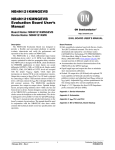
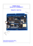
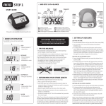
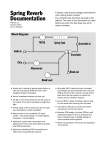
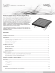
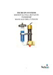
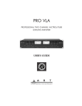
nonlinearcircuits cellF action build guide & BOM VERS. 1 Please read thru before soldering anything, there are some component values that need to be changed or decided upon before starting. If you spot any errors please let me know and check for updated versions of this guide. BOM notes 1. get spares of everything, you might drop some, destroy some whilst soldering or I miscounted 2. read the build notes regarding component choices following the BOM before going shopping (particularly regarding the pots, jacks, LEDs and capacitors) Component power connector Quantity 1 Notes Molex, .156 in KK, up, 3 pin OR regular 10 pin Euro-rack power connector Kobiconn type 3.5mm jacks DPDT on-on toggle switch 4PDT on-on toggle switch 250k pot (100k ok if difficult to get) 100k pot 75 1 1 1 23 TL074 (TL084 ok) TL072 4013 4024 4046 4070 DG411 NJM13700 TLP291-4 12 2 1 1 1 1 1 3 2 PT2399 2 SMT SOIC 0.050 pitch SMT SOIC 0.050 pitch SMT SOIC 0.050 pitch SMT SOIC 0.050 pitch SMT SOIC 0.050 pitch SMT SOIC 0.050 pitch SMT SOIC 0.050 pitch DMP16 see build notes SMT SOIC 0.050 pitch – see build notes DIP single vactrol 4 Silonex NSL-32 or similar LED 5mm 10 LED 3 pin dual (common cathode) LED 2 pin dual (bipolar) 5 1 L1, L2, L6, L7, L8, L9, L10, L12, L13, L14, L3, L4, L5, L11, L16 L15 2k multi-turn trimpot (5k ok) 1 20k multi-turn trimpot 100k multi-turn trimpot 100k single turn trimpot 1 2 1 see build notes see build notes see build notes 3269w 3269w 3269w 6mm top adjust 10uF electro 38 100uF electro 8 25V or higher rating, Lead spacing 0.079 inch (2mm) Unmarked electros on PCB can be 10uF-100uF but included in the 10uF count, used for decoupling 25V or higher rating, Lead spacing 1000uF 2 10uF BP or NP 6 J108 or J112 FET BC557 (PNP) 4 5 BC547 (NPN) 78L05 1N4148 1N4004 1k tempco 28 1 18 2 2 0.1 inch (2.5mm) 25V or higher rating, 5mm spacing 12.5mm diameter Lead spacing 0.1 inch (2.5mm) marked ‘gsd’, TO-92 marked ‘p’, TO-92, The two for the QUO should be matched, if you care about that sort of thing. marked ‘n’ or unmarked, TO-92 TO-92 thru-hole thru-hole marked ‘1kT’ draped over transistors in QUO and VCO sections ALL RESISTORS AND CAPACITORS LISTED BELOW ARE 0805 100R 220R 470R 1k 2k2 3k 3k3 4k7 5k6 6k2 7k5 8k2 10k 15k 18k 22k 24k 30k 33k 39k 47k 56k 68k 91k 100k 120k 150k 200k 220k 300k 470k 680k 820k 910k 1M 6M8 10M RL 1 11 2 64 11 1 1 4 1 1 1 1 51 2 1 4 1 4 6 1 14 1 1 1 91 2 6 16 3 1 5 1 1 1 4 1 1 21 0805 – select value to suit LED brightness 20p 22p 47p 151 (150p) 102 (1n) 222 (2n2) 103 (10n) 473 (47n) 104 (100n) 105 (1u) 1 1 2 4 6 1 4 4 68 3 Purchasing components Capacitors Try to find good quality capacitors. The ones from Tayda are not so great (they will work but I suspect the tolerances are at least +/20%). Many of the 100nF (104) caps are for decoupling so you can use whatever, but for the DP filter, be sure to use good 100nF. The 2n2 (222), 150pF (151) and 1nF (102) are used in the VCO and QUO/LPF so get good ones for these. Look for good tolerance +/-5% or better and low leakage, in the 0805 range there are plenty of choices and they are very cheap. There are a number of unmarked electro capacitors on the PCB. These are for decoupling so you can use 10uF (the quantity is included in the 10uF count) but feel free to install a larger value if you like, such as 100uF. Jacks Use Kobiconn types Pots and toggle switches The 4PDT toggle switch has a fairly high profile, which means you want to find pots with slightly longer shafts than usual. Or mount the pots so they are sitting a bit off the PCB (a PITA). Of course buy a 4PDT toggle switch with the lowest profile you can (probably 13mm) I use pots from Song Huei as shown below with L=25mm These do not have a thread to bolt to the panel. The large number of jacks means the PCB is firmly attached to the panel except at one end (where the mixer is) these two pots are the standard threaded 9mm ones from Tayda and are bolted to the panel. The unthreaded 9mm pots at Tayda have very short shafts and are not suitable for this project. This page on my blog has several pictures of a completed panel/pcb : http://nonlinearcircuits.blogspot.com.au/2014/12/cellf-panel-pcb-pics.html The picture below shows the two pots bolted to the panel and the others are not. Note these two pots are raised a little off the PCB, but the connection is very firm once the side tabs are soldered. NJM13700 These are an unusual wide package: DMP-16, though easy enough to find from the larger retailers. The SOIC package LM13700 should fit on the solder tabs, with some careful positioning. TLP291-4 This is a quad opto-coupler package. There are a number of different versions made by various companies, most will work, but be sure the internal components and pinout matches the one shown below. Check with me if you are not sure. LEDs As mentioned in the BOM, select RL values to suit your LEDs. You may need to go back and change some of these once the board is running, it is easy to replace 0805 parts, heat them up and flick them off! The 3 pin dual LEDs are used in the Divider, QUO and FF chaos. For the latter two, it does not matter which way they are installed, but for the Divider it does. If your 3 pin dual LEDs are red/green (most common), you should install red LEDs for /16 and /32 (the top two LEDs) and then install the 3 pin dual LEDs so the red side is activated by /64, /128 and ‘stair’. The green LEDs light up for the /2, /4 and /8 outputs. The LED positions on the PCB are logically laid out so the hole closest to the nearest jack is the hole that corresponds to that jack. The image below is an example, the left side LED hole is for LED corresponding to the staircase output, the right side hole is the one for the /8 output. The centre hole is the common cathode. The two pin bipolar LED (L15) is used for the Sloth Chaos. KLUDGES The Slew sub-circuit of the Logic module needs 5 fixes. See the diagram below. It would be best to solder on the revised resistor values first and just mark the transistor to be changed with a pen to sort out when you are installing the transistors. 1. 2. 3. 4. 5. replace 22k with 100k replace 100k with 10k replace 100k with 10k replace PNP transistor with NPN transistor installed facing the ‘wrong direction’ After installing the NPN transistor, next to L10, solder 47k across the middle and upper pins (the collector and the base), this can be done underneath the PCB for easiest access. Building 1. 2. 3. 4. 5. 6. 7. 8. 9. Start with low components; resistors 0805 caps and then ICs. Once these are all on, start on diodes & transistors. The highest components, the electros come last. Check several times as it is easy to miss components. Attach the jacks to the panel and the pots & switches to the PCB without soldering anything. Attach the PCB to the panel, ensure none of the jack tabs get bent under the PCB and are poking up thru the holes. Tighten up the switch nuts, but not too much as the threaded shaft can break free of the switch body. I usually do finger tight and then a 1/8th to a ¼ of a turn with a spanner. Tighten up the nuts on the two threaded shaft pots at the mixer end of the panel. Ensure all the pot shafts are straight and turn easily, then get soldering. When all the pots, switches and sockets are soldered on, you will need to remove the PCB from the panel to solder on ground connections for the jacks (unless you used Thonkiconn jacks). Maybe you can be lazy and just solder on the ground wires to the easily accessible jacks and rely on the panel to do the rest of the ground connection….I probably wouldn’t do that, maybe Testing This section will give a description of each module and discuss how to test them. Some modules, such as the VCA, need to be setup before they will work properly. Setup instructions are in the next section. The QUO/LPF, VCO, Chopper, DelayNoMore, Sloth, FF Chaos and DP filter have all been released as individual modules, check the build guides for these for more information - http://www.sdiy.org/pinky/data/data.html Divider Patch a clock signal, a square-wave from a LFO, into the clock input. The LEDs should start indicating the outputs are high or low. Check the outputs are giving approx. 5V gate signals. The stair out will look like a sawtooth at higher frequencies but should show obvious steps at lower clock frequencies. The stair is made up of the Divider outputs run thru a R2R ladder. Logic Leave the Divider running and patch some of the outputs into the Logic inputs, you should see the LEDs lighting up and be able to obtain varying gate signals from the outputs. The Logic uses a 4070 XOR chip. The slide output is similar to the smooth output of the Buchla265 SOU and is made of the logic gate outputs run thru a R2R ladder. Patching a CV or gate signal into the slew jack should vary the slide output signal from very smooth to stepping. There is a trimpot to preset the slide output, see the setup section. QUO/LPF See the setup section for tuning info. When the Q pot is turned up to 9 or 10, the module should self-oscillate and can be used as a Quadrature LFO or VCO depending upon the setting of the Range switch. The dual LED should indicate oscillation in low freq mode, but will stay on all the time at higher frequencies. If you wind back the Q pot and patch in an audio signal, the module will operate as a very useful low-pass filter, adjust the freq pot to find the sweet spot. VCO See Setup section for tuning. Check the outputs for tri and square waves. VCA Will need to be setup before it will work, see Setup section. Chopper Patch CV signals into the ‘comp’ and chop2’ jacks and adjust pots, the LEDs should start flashing and you should be able to obtain CVs from the ‘chop’ and ‘chop slewy’ outputs, plus gates from the two gate outputs. Delay No More Patch in some audio signal and monitor the outputs whilst tweaking the pots, expect all kinds of garbled stuttering carcrash noises. Patch in some CVs to automate this process. Note the version on this PCB is different to the stand-alone version. This one has vactrol based CV control of both delay stages. DP Filter See Setup section. Patch in an audio signal and check the outputs. At some pot settings there will be no signal from the ‘trans’ output as this section needs to be ‘turned on’ by the diode ladder. This filter is quite uncontrollable, especially when the resonance feedback paths are switched over. Another fun thing to do is patch unused outputs back into the spare input or FM jack. Vactrol Pill This is basically a noise module that makes blips, squirts and various video game type noises. It needs a CV signal into CV1 or CV2 to operate. CV1 and CV2 control different functions so it is best to give it two signals in order to get the most from this module (gates and triggers are good too). Then FM input is for audio rate signals which will phase modulate the VCO output, this appears at the ‘pm’ output. Sloth Chaos This chaos module takes 15 minutes to complete a cycle. The pot allows you to vary the cycle time between 12-16 minutes, though it may be 2 hours before any effect takes place. The LED changes colour when the ‘big’ output is a positive or negative output. Usually it will change colour every 15 minutes or so, but sometimes it will not change for up to an hour. The ‘big’ output is a voltage ranging from +10V to -10V, the ‘small’ is approx. +/-3V. The signals are different as they are extracted from different parts of the circuit. The best way to test the Sloth is to plug it into a VCO and listen for the VCO pitch to slowly change over a few minutes. FlipFlop Chaos To test, patch a gate signal into ‘gate’ and monitor the outputs. Add a CV, adjust the CV pot to increase its effect. Offset Mixer This mixer can handle audio and CV signals. An important point: if nothing is patched into jacks 3 and 4, pots 3 and 4 can be used to add a positive or negative DC offset to the output of the module (the two outputs are the same). It is important to keep pots 3 & 4 turned to 0 if you do not want to use the offset function. Patching anything into jacks 3 & 4 disconnects the offset voltage from the circuit. Setup This section covers the trimpots, assuming everything is working. Single turn 100k trimpot in Logic module This gives an offset to turn on the slew vactrol. To set up, put a clock signal into the divider, patch some of the outputs of the divider into the logic input and monitor the slide output. If you have an oscilloscope, that is best, otherwise patch the slide output into a VCO and listen to the VCO output. You should be able to see/hear the difference between stepping voltage changes and slewed voltage changes when you adjust the trimpot and nothing is patched into the slew input jack. I set the trimpot so the slide output is slightly slewed. A positive CV signal or gate on the slew input decreases the amount of slew, squaring up the signal from the slide jack. A negative CV increases the slew. 100k multi and 20k multi in VCO module The 100k multi-turn trimpot is used to set the VCO so there are no dead zones on the panel mount ‘tune’ pot. You should get approx. 18Hz to 11.5kHz from this VCO, just adjust the 100k trimpot so you can get this range from the ‘tune’ pot. The 20k multi-turn trimpot is used to get 1V/octave tuning. This VCO is not designed to be the most stable, drift-free oscillator ever invented (note the lack of matched transistors), generally expect to get good tuning over a three octave range. Anyway, the simplest way to tune the 20k trimpot is to set the VCO to cycle at 220Hz. Patch in 1V to the CV jack, adjust the 20 trimpot so the VCO is now at 440Hz. Patch in 2V and hope to see 880Hz, adjust 20k trimpot to make it so. Go back to 1V CV and adjust to get 440Hz, remove the CV patch and adjust to get 220Hz. It takes a few times until the values are near enough for 0V, 1V and 2V, don’t be too anal about it. 2k multi-turn trimpot in DP Filter module This is used to set the range of the Tr Freq pot. Patch an audio signal into the filter and monitor the output of the transistor ladder (trans). Adjust the FrD and Qd pots so the transistor ladder is active. Adjust the Tr freq panel pot to see how much of an effect it has, tune the 2k trimpot so the panel pot has a greater active range. If you want to more technical procedure, google the Minimoog Service manual and check sections 5.13 and 5.14 (filter scale), really though the DP filter is not designed to be so precise, none of the transistors are matched for a start and the transistor ladder is fed audio by infra-red from the LEDs of the diode ladder. 100k multi-turn trimpot in VCA module Set the trimpot to approx. middle position Patch an audio signal into the input jack, monitor the output. Patch a 5V signal into the CV jack and adjust the trimpot so the output is approx. the same amplitude as the input. It is quite a sharp change, but near enough is good enough. The idea is you want unity gain for a 5V CV signal. Schematics For the DP Filter, please download the DP filter BOM & manual from http://www.sdiy.org/pinky/data/bp.html The only changes from the stand-alone version are the use of quad package opto-couplers and R3 is replaced with a 2k trimpot.