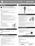
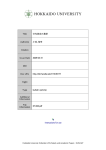
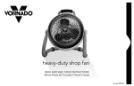
1
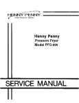
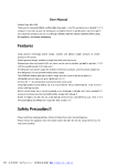
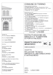
Galley Manual 1/23/01 3:15 PM Page 2 Galley Line ® Warranty, Installation, Parts and Service Manual Modular Products For: Foodservice, Healthcare, Scientific, and Laboratory Use Gal l eywar r ant st ot heor i gi nalpur chaserofever ynewGal l ey modul et hatsuchmodul e,andal lpar t st her eof ,wi l lbef r ee f r om def ect si nmat er i alandwor kmanshi pundernor maluse &ser vi cef oraper i odst at edonyouror der . Gal l eyof f er s3war r ant i esf orpur chasewi t hdi f f er ent" l engt hs ofcover age" .Pr oductpr i ci ngvar i esdependi ngupont he war r ant ysel ect edatt i meofor der .Eachwar r ant yi ncl udesal l l aborandal lpar t si ncl udi ngt hecompr essorandcondensi ng syst em.Thewar r ant yt hatappl i est oanor derwi l lbeshownon quot at i ons,acknowl edgement s,andi nvoi ces.Theavai l abl e war r ant i esar e:A)5year s:l aborandpar t sasbel ow.B)1year : l aborandpar t sasbel ow.C)90days:l aborandpar t sasbel ow. Dur i ngt hi swar r ant yper i odGal l eywi l lr epai rorr epl aceany def ect i vepar torpor t i ont her eofsentt oGal l eybyt heor i gi nal pur chaserwhi chGal l eydet er mi neswasdef ect i veduet of aul t y mat er i alorwor kmanshi p.Theor i gi nalpur chaserwi l lpayl abor f orcr at i ng,f r ei ghtandr el at edcost si ncur r edi nt her emovalof t hemodul eandshi pmentt oGal l ey .Gal l eywi l lpayt her et ur n f r ei ghtcost si ft hemodul eorpar tt her eofwasdef ect i ve. Thet er m“ or i gi nalpur chaser ”meanst hatper son,f i r m,assoc. orcor por at i onf orwhom t heequi pmentwasor i gi nal l yi nst al l ed. Thewar r ant ydoesnotappl yt oanymat er i alt hathasbeen subj ect edt oshi ppi ngdamage,i mpr opervol t age,i mpr oper i nst al l at i on,mi suse,negl ect ,al t er at i on,oracci dent ,suchas acci dent aldamaget ot heext er i orf i ni sh,andt oanyr ef r i ger at ed uni torpar tt her eof ,whi chhasbeenr epai r edoral t er edbyot her t hanGal l eyi nanywaysoasi nourj udgementt oaf f ecti t squal i t y oref f i ci ency .Thi swar r ant yal sodoesnotcovert her ef r i ger at or dr i erorl i ghtbul bs.Thewar r ant yi ssubj ectt ot heor i gi nal pur chaser ’ snor malcar eandr esponsi bi l i t y ,suchascl eani ngt he condensercoi landi si nl i euofal lot herobl i gat i onsofGal l ey . Gal l eyexpr essl ydi scl ai msal l ot herwar r ant i es, whet her wr i t t enoror al , expr essori mpl i ed, i ncl udi nganywar r ant yof per f or mance, mer chant abi l i t y , orf i t nessf orapar t i cul arpur pose. Thi swar r ant ysuper sedesandexcl udesanypr i oror al orwr i t t en r epr esent at i onsorwar r ant i es.Gal l eynei t herassumes,nor aut hor i zesanyot herper sont oassumef orGal l ey ,anyot her l i abi l i t yi nconnect i onwi t hourpr oduct s. I nnoeventwi l lGal l eybel i abl ef orspeci al ,i nci dent alor consequent i aldamages,orf ordamagesi nt henat ur eof penal t i es.Nocl ai mscanbemadeagai nstt hewar r ant yf or spoi l ageofpr oduct sonaccountoff ai l ur e.Thesol eand excl usi ver emedi esandt hef ul ll i abi l i t yofGal l eyf oranybr each oft hi swar r ant ywi l lbeaspr ovi dedi nt hi swar r ant yandi sl i mi t ed t ot hepur chasepr i ceoft hepr oduct s.Pur chaser ’ ssol er emedy i st her epai r ,r epl acementorr ef undoft hepur chasepr i ceon nonconf or mi ngpr oduct s. I fshi pmentofar epl acementpar ti sr equest edpr i ort ot he ar r i valatGal l eyoft hepar tcl ai medt obedef ect i ve,t heor i gi nal pur chasermustacceptdel i ver yoft her epl acementpar tona C. O. D.basi s,wi t hcr edi tbei ngi ssuedwhent hedef ect i vepar t hasbeenr ecei vedandi nspect edatourpl antandpr ovedt o bewi t hi nt hi swar r ant y . Per f or mancebyGal l eyundert hi swar r ant yi scont i ngent uponcausesbeyondGal l ey’ scont r ol .Gal l eyshal lnotbel i abl e f oranydef aul tordel ayi nper f or mancet her eundercausedby anycont i ngencybeyondGal l ey’ scont r ol ,i ncl udi ngwar , gover nment alr est r i ct i onsorr est r ai nt s,st r i kes,f i r e,f l oods,act s ofnat ur e,shor torr educedsuppl yofr awmat er i al s,or di scont i nuanceoft hepar t sbyt heor i gi nalpar tmanuf act ur er . Thi swar r ant yappl i esonl ywi t hi nt hecont i nent alUni t ed St at es.I nAl aska,Hawai i ,Puer t oRi coandCanada,t he war r ant yappl i esonl yt oandi sl i mi t edt ot hesuppl yof r epl acementpar t satt heBuyer ’ sexpense. War r ant yExcl usi ons 1.Pr obl emsduet ooper at i onatvol t agesot hert han speci f i edont heequi pmentnamepl at es. 2.Pr obl emsduet ot heuseofcl eaner snotr ecommended i nt hi smanual . 3.I nst al l at i on,l aborandj obcheckout sar enot consi der edwar r ant y . 4.Repl acementofi t emssubj ectt onor malwearsuchas aknobs,l i ghtbul bs,br eat hguar ds,et c. 5.Repl acementofi t emssubj ectt omi suse. Galley Manual 1/23/01 3:15 PM Page 3 Galley Line ® INSTALLATION INSTRUCTIONS FOOD SHIELD INSTALLATION PROCEDURE CANOPY INSTALLATION PROCEDURE 1. Remove screw (A), located at both ends of the canopy. 1.2. Lift Laypanel out (D) mounting brackets on the top where desired. straight up to disengage andcounter pull the bottom of the panel toward the center of the unit. the panelwill which canabeclearance set aside. hole for the electrical conduit. Drill a ½” hole in the counter top where the 2. This Oneshould of thefree brackets have A 3. Removewiring the nutswill andfeed washers from the 8 studs (B) on the table top (4 at each end). Place the canopy electrical through. over the studs, making sure the end with the electric wiring matches the wired end of the table. 3. Replace Mount the brackets to and the tighten. counterIMPORTANT: top. the 8four washers and nuts Do not overtighten. 4.4. Connect Feed flexible conduit through the ½” hole in the counter top.and will only fit one way. the electrical harness connector halves together, This is polarized C (Not Shown) NOT CONNECTOR. 5. DO With theFORCE four posts over the brackets and firmly touching the counter top, insert and tighten the screws through the posts 5. Carefully fold harness into inside of canopy upright and replace panel (D) and fasten with screw (A). into the mounting brackets. 6. Remove the black plastic knobs from the studs (c) (not shown). Install the clear plastic food protector, replace and tighten the black plastic knobs. DO NOT OVERTIGHTEN. 7. Instructions for drilling stud holes in clear acrylic buffet canopy. A. Blanket a work table & remove tools to prevent plastic from being scratched. B. Raise breath guard & test to see if studs align with pre-drilled holes in canopy. C.For, those studs that do not align, mark plastic where a hole should be or where the hole needs to be enlarged. D. Put 3"square piece of masking tape on each side of plastic over where hole is to be drilled. E. Use no oil; protect surface from scratching; drill hole; remove duct tape; mount plastic. HOT FOOD PROTECTOR AND DOUBLE DECK DISPLAY STAND INSTALLATION PROCEDURE Hot Food Protector BREATH GUARD TOP SHELF D.D.D.S. TOP SUPPORT BOTTOM SHELF BREATH GUARD HFP SUPPORT 10 x 1/4 Truss Head Machine Screw / Leg Mounting Bracket Assembley LINE UP Double Deck Display Stand SHELF 1. Set accessory on table close to mounting location. 2. Lift up right leg (as viewed from server’s side), and pull out upper wire harness (about 3 inches). Connect upper and lower wire harness (A). 3. Push wire harness up leg, and set accessory on mounting brackets and stud. Caution: Care must be taken not to damage wiring during installation. 4. Install screws (B) and nuts (C), and tighten. 5. Remove black plastic knobs under shelf, and install plastic breath guards. 1. Place modules and end, allowing the male/female “Matelock” interlocking ends to face each other. 2. Push modules together to form the desired self-aligning, self-locking serving line configuration. 3. Lock the wheel toe brakes of each module as you set it in place in the serving line-up. To easily separate the modules, release the toe brakes, grip the push handle and pull while exerting a slight twisting action on the push handle. On Cafeteria Modules with Trayslide, Port-a-clamp Locking Device #9000877 should be used to attach each individual trayslide to the adjacent unit. B KNURLED NUT MALE END D.D.D.S. BOTTOM SUPPORT FEMALE END WHEEL TOE BRAKES (On all wheels) TRAYSLIDE TRAYSLIDE TRAYSLIDE CLAMP #9000877 TRAYSLIDE PROCEDURE FOR FIELD INSTALLATION OF CUTTING BOARD 1. When trayslides are in the vertical position, they may be swung into the horizontal position by grasping the front edge and lifting out until the trayslide locks into place. 2. The trayslides of the entire serving line may be fastened together with the aid of an interlocking device that levels the trayslides, part 9000877. Proceed to find the center line for the mounting brackets by the same method as used with the trayslide. Place bracket spacer, long end down, against the top edge of the unit. Using a square, align bracket spacer with center line and center punch. Using a #7 or 13/64 dia. drill and 1/4-20 tap, drill land tap the locations that are center punched. Mount the cutting board with the 1/4-20 x 12 truss head screws provided. PROCEDURE FOR FIELD INSTALLATION OF TRAYSLIDES Place back edge of trayslide on top and align ends of trayslide with unit. Using a pencil, mark the top hole of the bracket. This locates the center line for mounting the brackets. Using a square to locate the center line, center punch 4-13/16” and 7-1/8” down from the top. Using a #7 or 13/64 dia. drill land 1/4-20 tap, drill and tap the locations that are center punched. Mount the trayslide with the 1/4-20 x 1/2 truss head screws provided. The Port-A-Clamp will fasten the front edge of the trayslide together for added rigidity. MISCELLANEOUS 1. The Silverware Dispenser may be mounted to face either the front or back by removing the cap screws from the studs and reversing the unit. 2. The End Shelf and Low End Shelf may be mounted on either end of the module. Align the End shelf brackets with the push handle and push down until the top is flush with module top. 3. The Transition Section (“Mateflat” End Panel) is installed by aligning REMOVABLE INTERIOR SHELVING 1. The brackets which supports for removable interior shelving are factory installed. 2. The shelving is placed into position by inserting it through the opening on the server’s side of the Galley units. 3. If repositioning of the shelving is desired, this can be easily accomplished by drilling new holes and rebolting the support to the new location. the male/female “Matelock” features and by pushing the gripper clips onto the push handle. Level the Transition Section by adjusting the bullet feet tightly to the floor. 4. The top of the Deluxe Cashier Module may be positioned at either end of the module. Remove the diagonal cross brace from the top and bottom, then remove the four mounting bolts for the top. Reposition the top, install the four mounting bolts, and install diagonal cross brace. 3 Galley Manual 1/23/01 3:15 PM Page 4 Galley Line ® OPERATION INSTRUCTIONS GENERAL OPERATION Remove the side access panel that is convenient to the electrical controls as follows: 1. Grasp the bottom edge of the side access panel and slide it up. 2.Then pull the bottom of the side panel towards you and lift out. 3.Plug electrical cord into proper receptacle and then switch on the overhead canopy light. • Hot well module has individually controlled wells. Turn dial to “6” for normal operation. • Refrigerated cold module has one main temperature control. • Utility module does not have a control. • Replace the side access panel by reversing the removal procedure. • On entree module, adjust position of overhead heat and light canopy by twisting the two hand knobs on the vertical upright. The light control is located in the canopy housing and the temperature control is located in the control box (see drawing). HOT WELL AND SOUP MODULES- 9010, 9011, 9012 and 9030, 9054 1. Each rectangular or round hot food well is controlled by a separate infinite switch controller located on the electrical control panel. 2. It is recommended that wells be preheated for approximately 30 minutes at a setting of HI initially and adjust as needed, prior to inserting food service pan from oven or holding cabinet. Foods preheated to a minimum of 160° should be used. It is intended that the hot wells will maintain pre-heated foods during a 2 hour serving period. 3. The Hot Wells are intended to be used DRY. Water should not be used. 4.6” Deep food service pans may be used in hot well with the use of #8750 Hot food Well Pan Adapter. 5. Caution: Never place food directly into warmer well. Always use an inset pan. 6. The hot well will discolor from heat. To clean the hot well, use a stainless steel cleaner or mild abrasive. Do not use steel wool. Use a plastic scouring pad. Rinse with vinegar and water solution to neutralize detergent cleaner residue. HEAT LAMPS ON BUFFET STYLE MODULES 1.Each Heat Lamp in controlled by a separate ON-OFF Switch located underneath the end of the canopy. 2. CAUTION-DO NOT USE OVER 150 watt bulbs. 125 watt is recommended. REFRIGERATED AND FREEZER MODULES-START-UP 1. Connect Module to proper power source (120V AC, 60Hz, 15 AMP 1 Phase). 2. Turn unit one. 3. With an ambient room temperature of 75°, allow 60 to 90 minutes on Refrigerated Modules and 120 to 180 minutes on Freezer and Refrigerator/Freezer dual temp modules to pull down to operating temperature before loading with food. This allows the interior to cool down to the correct storage temperature. The thermostat is preset at the factory to maintain an average interior temperature of 38°F (3.3°C). 4.On sandwich preparation modules, it is recommended that the covers be kept in the closed position when the module is not in use. All pans should be in the top at all times. REFRIGERATOR AND FREEZER MODULES -ADJUSTMENTS 1. Refer to cleaning instructions below and remove the access control panel as outlined. 2.The temperature adjustment control is located inside the compressor housing and temperature may be adjusted by turning the adjustment knob. 3. The 9214, 9234 and 9244 Refrigerated Modules are especially designed to adjust the temperature downward for use with milk shakes. 4.If unit cannot be adjusted to desired temperature contact you nearest authorized Galley Service Agency. 4 REFRIGERATOR AND FREEZER MODULES- CLEANING CONDENSING UNITS Condensing units for refrigerated chest type models have a slide out 1. Unplug Module condensing unit for ease in cleaning and servicing. 2. Remove side panel 1. Remove plasticplastic side panels on both sidesexposing by grasping the bottom edge of the panel, sliding it up, and pulling it out toward you. compressor housing. 2. Remove thumb screws for condensing unit compartment access panels; 3. (4)Remove four on each the side. four screws on the louver panel 3. Unplug condensing unit cord from receptacle in compartment from exposing the condenser. operator side. 4. Replace louver panel, screws, and plastic. 4. Remove thumb screw fastener in slide out base from customer side. 5. Grasp edge of slide out base from customer side and pull out slowly to expose the condenser for cleaning. 6. Replace by reversing the above procedure. SALAD BARS-TO DRAIN COLD WELL To Drain Cold Well module, remove side panel. Place drain pan, or bucket on the floor beneath cold well drain. Open drain valve and drain. CONVECTION HOT FOOD MODULES #9056 &9057 1.Preheat for approximately 20 minutes with lids on unit. 2.With a dial setting of 8 to 9, sandwich type packaged food will take approximately 1 hr. to heat to serving temperature of 140 to 165 F. 3. With a dial setting of 7 to 8, convention type A will take approximately 1 hr. and 15 minutes to heat to serving temperature from refrigerated state. 4.Partial loads will require less time. 5.During serving period, lids may be removed and stored in Utility Unit. Preheated foods will continue to be maintained at serving temperature. 6. ON-OFF Switch may be operated by reaching under side panel on lower right side. To adjust heat setting on control box, it is necessary to remove the side panel. ADJUSTMENTS 1.With a setting of 10 on the thermostat dial, the tank ambient temperature will cycle between 210°F and 220°F after approximately 20 minutes preheat and with lids in place. 2.If unit does not perform within this range proceed to adjust, using the following steps. 3.Suspend a temperature measuring probe in the center of the unit. Measure temperature with lids closed. 4. To adjust, pull knob from thermostat stem. 5.Locate center screw in stem. A clockwise turn decreases and a counterclockwise turn increases temperature. 6.A quarter turn of the center screw in either direction will equal approximately 15° to 20° Fahrenheit. 7.Recheck temperature after unit has stabilized by operating module, and after thermostat pilot light has cycled three times. CLEANING PLASTIC CAUTION: Always turn power OFF and disconnect electrical cord from power source before performing ANY cleaning or maintenance. PLEXIGLAS–should be washed with a mild soap and luke warm water solution using a soft cloth or sponge. Apply liberally and blot dry. Grease and oil can be removed with hexane or naphtha (plexiglas only) followed by washing. A period waxing with a good grade of hard automobile paste wax (not cleaner-wax) will help maintain a beautiful luster. DO NOT USE– window cleaning sprays, scouring compounds, or solvents such as: acetone, gasoline, benzene, carbon tetrachloride, lacquer thinner. etc. ABS–should be washed with a mild solution (5% or less) of detergent and warm water. The solution should be rinsed off with water and wiped dry. NEVER– scrape the plastic to remove dirt. CLEANING STAINLESS STEEL SURFACES Clean with soap and water solution. Rinse and wipe off dry. Rub with the grain or polish lines. A stainless steel cleaner may be used after cleaning with soap and water. A high luster can be obtained by applying baby oil or lemon oil. Galley Manual 1/23/01 3:15 PM Page 5 Galley Line ® PARTS REMOVAL INSTRUCTIONS GENERAL INSTRUCTIONS MODULE PARTS Description 1. Read manual before attempting to make any repairs. 2. Replacement Parts are on Pages 8 through 10. 1 2 3 4 Side Skirt Access Panel Female End Panel Ass. Male End Panel Ass. Flat Ends 5 6 7 8 Side Skirt Access Panel Female End Panel Ass. Male End Panel Ass. Flat Ends 9 10 11 12 Side Skirt Access Panel Female End Panel Male End Panel Flat Ends 16 13 14 15 16 Side Skirt Access Panel Female End Panel Ass. Male End Panel Ass. Flat Ends 19 17 18 Side Panel Female End Panel Ass. Male End Panel Ass. Flat Ends 1 3 3. Disconnect unit from electrical outlet before servicing. 2 4. Wiring Schematics are shown on Pages 11 through 15 4 5. Electrical Data is on the Name Plate. 6. Include Model Number and Serial Number on In-Warranty Report. 5 7. Parts replaced require authorization to return. 8 7 6 GENERAL PARTS REMOVAL 1. Side Panel is removed by raising panel up 3/4” to 1” and then pulling out at the bottom. 2. Side Skirt is removed.by feeling along the bottom edge of the plastic side skirt, to locate the truss head screws that hold on the plastic side skirt to the side skirt bracket. First remove these truss head crews and then remove the plastic side skirt. 9 11 12 10 3. Bottom Panel on Heated Units--remove screws and take off panel. 4. Hot Food Well — after removing Side Panel, Side Skirt and Bottom Panel, remove two hangers by loosening and removing two bolts, nuts and lock washers from each. The hot well is held in place by two spot welds, one each on the center of each side fastened to the top, that could be broken with a chisel. This would only be necessary if the entire hot well or inner pan were being replaced. Service on the Hot Well itself, such as replacing an element, may be accomplished by removing the bottom cover of the hot well which is held in place by four screws. 5. Food Breath Shields Guard andand Breath Guard Supports 5. Over Counter Displays. A. Simply remove the 4 black knurled knobs (2 located at each end underneath the canopy) and remove the entire one piece Breath Guard. Unplug the unit. a. b. Disconnect the wiring in the main control box and free the 6. Buffet style Canopy from Module conduit from its fitting. A. Remove Pylon covers inside Canopy Pylon by Loosening the 10-32 c. Unscrew fourend mounting screws in the legs. screws the on each at the top. d. Lift the unit flexible conduit through the B. Slide Panelvertically up and pullpulling bottom the outward. topC. Disconnect Harness Pylon Connector Carefully. 13 15 14 18 19 17 CANOPY PARTS D. Remove four 1/4-120 nuts from each side. E. Lift Canopy off and carefully lay aside. 7. Canopy Cover from Buffet Style Canopy — the bottom edge should be pulled toward serviceman and lifted off as the plastic is flexible. 8. Double Deck Display Shelves and Food Protectors A. Remove Knurled nuts on the front legs. B. Remove truss head screws from rear leg. C. Lift up gently so wiring is not damaged. D. Disconnect connector halves and lay aside entire assembly. E. To remove plexiglass for cleaning or replacement, unscrew the black knurled knobs underneath the shelf. Buffet - Lighted Buffet - Heated 9. Condensing Unit A. Remove After removing side panel from refrigerated cold pan unit, then remove a. all access covers. six screwsbolts from Access Cover. b. Remove holding condensing unit to the housing. On refrigerated chest type models #9214,9215,9234, c.B.Disconnect the refrigerant lines 9235,9244,9245 andunit 9249, remove the thumb screws from condensing d. Pull condensing through front opening. unit compartment access panels; (4) four on each side; unplug cord from receptacle in compartment; on other side remove thumb screw fastener in slide out base; grasp edge of slide out base and pull out slowly to expose the condenser for cleaning or servicing. Food Protector Double Deck Display Description Pewter Tan Shelf Dove White Shelf Black Pearl Shelf Stainless Shelf Breath Guard,Clear Portable Breath Guard Entree Breath Guard Pewter Tan Shelf Dove White Shelf Black Pearl Shelf Stainless Shelf Breath Guard,Clear Pewter Tan Shelf Dove White Shelf Black Pearl Shelf Stainless Shelf Breath Guard,Clear Pewter Tan Shelf 9” Pewter Tan Shelf 15” Dove White Shelf 9” Dove White Shelf 15” Black Pearl Shelf 9” Black Pearl Shelf 15” Breath Guard,Clear 5 Galley Manual 1/23/01 3:15 PM Page 6 Galley Line ® TROUBLE SHOOTING AND SERVICING INSTRUCTIONS HEATED MODULES-Model 9010 and 9030 to 9054 FREEZER/REFRIGERATOR MODULE- Model 9249 1. Hot Food Wells FREEZER TEMPERATURE ADJUSTMENT A. Trouble Shooting 1. DISCONNECT UNIT FROM POWER SUPPLY. 2. Remove plastic side panel on control box side. 3. Identify faulty hot food well element by performing a resistance test on the heating elements. This can be accomplished by setting all infinite switch controls to the “Off” setting and turning all switches Off. Attach the leads of an Ohm meter (accurate in the 5-200 ohm range) to the supply cord plug. Measurements should be made between the current carrying prongs of the plug. Turn the infinite switch controls on one-at-a-time, reading the resistance for each control individually. The resistance reading obtained should be as follows: 120V, 500W-29 ohms; 208V, 500W-86 ohms, 240V, 500W-115 ohms; NOTE; 3-Phase units will require relocation of the ohm meter leads so that accurate measurements from phase to phase can be obtained. NOTE: Remember to test only one element at a time, as measuring multiple elements can cause errors of measurements. If resistance readings are not within 5-10% or if element does not show continuity, proceed to the trouble shooting section for “Defective Infinite Switch Control.” If Infinite switch control process is OK, proceed to “Replacement of Element” Section. B.Replacement of Heating Element 1.DISCONNECT UNIT FROM POWER SUPPLY. 2.Remove plastic side skirt from unit. 3.Remove bottom cover from unit. 4.Remove hot well support angles (Four Bolts). 5.Remove bottom cover of food well. 6.Remove insulation. 7.Remove 3 screws holding heat sink to food well pan. 8.Examine and test element in hot food well to verify that it is defective and replace if found to be defective. 9.Remove terminal screws and replace element. NOTE: If terminals are badly oxidized or show sign of having arced, replace terminals with nickel plated steel-type ring-tongue terminals only; tin-plated copper terminals will not be suitable for the high heat environment. 10. To assemble, reverse the preceding procedure. 2. Infinite Switch Control A. Trouble Shooting 1. Follow steps 1 through 3 under hot food well above. 2.Remove electrical Control Box Cover. 3. If heating element resistance is found to be correct, determine proper continuity of control by first setting it to “Hi” position and checking for continuity from terminal L1 to H1, L2 to H2 and from L1 to P. Set Control to the “Off” position and check for no continuity between each set of terminals. 4.If proper continuity is observed, control may not be defective and other causes of the malfunction should be investigated. However, if control lis found to be defective, proceed to “Replacement of Infinite Switch Control.” B. Replacement of Infinite Switch Control 1. Remove control knob by pulling knob from shaft. 2. Unscrew lug nut that is located under knob and remove control from panel. 3. Disconnect terminals by carefully pulling them off, taking care not to damage the terminals. Damage to the terminals may prevent positive connections to the new control. 4. Install new control by reversing the preceding procedure. Be sure to orient the new control properly so that the “Off” position will be the same as for the original control. 5. Check continuity of control prior to final assembly of sheet metal parts to determine if defect has been corrected. 6 1. Remove plastic side panel on operator’s side (Lift up-Swing bottom out-Lower to remove) 2. Remove machine compartment access cover on operator’s side (4 screws). 3. Locate temperature control in upper right corner of compartment. 4. Check differential setting to be sure that it is set 5°F. 5. Check temperature setting control to be sure that it is set at approximately minus 100°F. If unit is running too warm, adjust control to a lower temperature If unit is running too cold, adjust control to a higher temperature. 6. Temperature measurements in the freezer should be made by sensing the air temperature approximately 2 inches above the bottom of the compartment in the center with the plastic cover for the compartment in place. REFRIGERATOR TEMPERATURE ADJUSTMENT 1. Remove plastic side panel and machine compartment access cover as shown for freezer adjustment. 2. Locate pressure regulating valve (large T-shaped assembly in machine compartment pipe). 3. The refrigerator cavity is controlled by a coil at a pressure of approximately 34 to 36 PSI. This pressure reading relates to an evaporator coil temperature of 320° to 35°F which will result in a cabinet air temperature of 380° to 42°F. Adjustment of this regulating valve should not be necessary, as it is pre-set when the unit manufactured. However, if the temperature of both cavities does not seem to balance properly, it may be due to the fact that the regulating valve needs to be re-adjusted. Adjustment should be made by a qualified refrigeration service technician only. 4. A low set pressure gauge should be attached to the Schrader valve on the regulating valve and the adjustment screw cover should be removed from the end of the regulating valve. Some foam insulation may need to be removed from the end of the regulating valve in order to gain access to the screw type cover. A 1/4” hex key wrench should be used to make the adjustment. Turning the wrench clockwise will increase the pressure setting turning counter-clockwise will decrease the pressure setting. Adjustments should be made approximately 1/8 turn steps allowing sufficient time for the system to re-balance before another adjustment is made. A nominal pressure setting of 34 lbs. on the R-12 scale on the low gauge is desired. It should be noted that the regulating valve setting is not dependent on the temperature control setting for the compressor. This temperature control setting of minus 100°F controls the cut off temperature for the compressor and maintains the minus 100°F temperature level in the freezer compartment Galley Manual 1/23/01 3:15 PM Page 7 Galley Line ® ELECTRICAL SERVICE HELPS HOT FOOD WELL MODULES GENERAL: To insure proper operation, this equipment must be plugged into a receptacle that can supply the full voltage as stated on the serial number label. Other appliances on the same line must not cause a voltage fluctuation exceeding 10% of what is on the name plate. Such voltage fluctuation voids the warranty. Trouble Possible cause Remedy Unit does not operate Insufficient electrical power to unit Defective Plug or Cord Original plug removed and replaced by plug configuration (See page 26 & 27 for NEMA numbers). Faulty Connection in control Box Check power source Check and replace if necessary Replace with proper plug Power switch defective Lamp does not light Burned out lamp Lamp contact not fully in sockets Lamp switch in canopy defective Harness pylon connector not fully assembled or contact is loose. Food Wells do not heat properly Supply wiring controls in control box defective User is not preheating sufficiently before placing Food Service Pans in unit which should be 160° to 175° when placed in unit User is putting water in bottom of heat well Direct blast of air conditioner Knob incorrectly mounted on control Infinite switch control defective Control box or hot well wiring defective Heating element or element terminals defective Check wiring diagram for specific model number Replace Replace Rotate lamp until contacts are fully in socket. If socket is damaged, replace entire fixture. Check wiring and replace if necessary. Check and re-connect or replace as necessary. Check wiring and terminals. See wiring diagram for specific unit Instruct user on proper operation. At setting of High on Infinite Control Unit should stabilize at 375° at bottom of well after approx. 45 minutes. Instruct user-Unit is intended to be used dry. Water in well limits top temperature. Relocate unit or shield from air conditioning Replace or re-align if necessary Check and replace if necessary. See “Infinite Switch Control” above. Check and replace if necessary. See “Hot Food Well” section above. Check according to “Defective Hot Food Well” section above. REFRIGERATED AND FREEZER MODULES Trouble Possible cause Remedy Unit does not operate or does not cool properly See Fig. 5, 6, 7, & 8, on page 13 of this manual Compressor needs cleaning. Temperature control not functioning properly Refrigeration leaks See Page 4 Adjust or replace as necessary Repair and re-charge 7 8 . 9 Galley Manual 1/23/01 3:15 PM Page 10 Galley Line ® PARTS LIST Entrée Module 9010 Infrared Warmer in Canopy Breath Guard Cutting Board 1/9th Size Stainless Steel Pan Heater Switch Fluted Torque Knob on Pylon Cross Knob Assembly (inside) Lamp Holder (socket) in Canopy Hot Well Assembly 120V Entrée Canopy Assembly Hot Well Heating Element 120V Breath Guard Knob Infinite Control 120V Pilot Light Lamp Toggle Switch Knob for Infinite Control 4040111 7000736 8766 2503006 4090002 2502034 9000513 4090163 9000500 9000524 4040060 2502049 4030033 4040015 4090279 2502035 Hot Wells - 4" Deep Used on 9010, 9030 thru 9054 Hot Well Assembly 120V Hot Well Assembly 208V Hot Well Assembly 240V Infinite Control 120V Infinite Control 208/240V On/Off Knob for Infinite Control Heating Element 120V Heating Element 208V Heating Element 240V Pilot Light Porcelain Bushing 9000500 9000501 9000502 4030033 4030022 2502035 4040060 4040061 4040062 4040015 4070288 Condensing Units 1/5 HP used on 9214 and 9215 1/4 HP used on all except 9214, 9215, 9245, & 9249 1/3 HP used on 9245 and 9249 4060014 4060012 4060081 Temperature Control Valve For refrigerators For freezers 4030016 4030041 Evaporator Regulating Valve For dual temp 9249 2605014 Toggle Switches For Lighted Buffet Canopies & Food Protectors For Heated Buffet Canopies & Food Protectors For 9010 Infrared heater For Chest refrigerator & freezers 4090260 4090279 4090002 4090004 Tray Slide Bracket Parts Acorn Nut S/S Lockwasher Zinc Flat Washer S/S Shoulder Bolt Tray Slide Clamp 2131001 2222005 2211010 2021029 9000877 Refrigerator & Freezer Lids Small Lids (22 1/2" X 21") Large Lid (22 1/2" X 28 1/4") 9002372 9002373 Casters 2707009 10 PASSTHRU/ SEETHRUREACHI NREFRI GERATORS-120Vol t ,1Phase PASS THRU /SEE THRU REACH-IN REFRIGERATORS -- 120 Volt, 1Phase Galley Manual 1/23/01 3:15 PM Page 12 Galley Line ® 18 12 NEMA CONFIGURATION FOR PLUGS 19 Galley Manual 1/23/01 3:15 PM Page 14 Galley Line ® SERVICE AGENCY NAME Certified Service Center Commercial Parts & Service Inc Commercial Parts & Service Inc Food Service Purchasing Chandler’s Parts & Service Reliance Commercial Service Bana Parts, Inc. Bana Commercial Service Pete DiPirro Company GCS Service, Inc. Ace Service Co Limited Mre Inc GCS Service, Inc. The Electric Motor Repair EMR Services EMR Services MRE, Inc. Restaurant Equipment Repari Micro Herros S.A. Sage Financial Commercial Kitchen Service Co Bildon Parts And Service Inc E&G Appliance Service GCS Service, Inc Midwest Food Equipment Service, Inc. Commercial Service & Install GCS Service, Inc Swanson Food Equip Svc Inc Town Center Inc GCS Service, Inc. Mr Gas Inc A&R Repairs Baker’s Kneads Inc General Parts GCS Service, Inc GCS Service, Inc GCS Service, Inc General Parts Inc GCS Service, Inc. Kaemmerlen Parts & Svc Commercial Kitchen Services GCS Service, Inc. Miller Ice Machine Company Camp Svc. & Parts Inc Commercial Parts & Service Inc Appliance Equipment Repair Service Enginieering Co. Whaley Foodservice Repairs Authorized Appliance Servicenter Natl Scale & Equipment Co Inc Whaley Foodservice Repairs Hobart Sales & Svc Authorized Appliance Servicenter Whaley Foodservice Repairs Whaley Foodservice Repairs Authorized Appliance Servicenter Authorized Appliance Servicenter Watkins Rest Equipment Company Whaley Foodservice Repairs Awh Corporation Authorized Appliance Servicenter General Parts & Supply Co., Inc. Goodwin Tucker Group National Service Cooperative Commercial Equipment Repair Casco Food Equipment Srvc Inc Tuv Essem Malachy Mechanical Maxwell’s Services GCS Service, Inc Jay Hill Repairs Public Service Company R&B Service Company Geoshare Sheet Metal/Food Service Meyers Electric Maintenance Burney’s Commercial Service GCS Service, Inc Burney’s Commercial Service Troutback Alpro Service Acme American Repairs Inc Hobart Sales & Svc A.I.S. Commercial Parts & Service A.I.S. Commercial Parts & Service Whitestone Refridgeration Inc A.I.S. Commercial Parts & Service All Service Kitchen Equipment Repair Blue Flame Northern Parts Distributor Reliable Dishwasher Rebuilders A.I.S. Commercial Parts & Service Duffy’s Restaurant Equipment Service Action Commercial Service Inc. J.B. Brady, Inc. Hobart Sales and Service GCS Service, Inc ARR/CRS Hobart Corporation Certified Service Center 20 14 DIRECTORY OF PARTS AND SERVICE DISTRIBUTORS ADDRESS 1051 Goodwin Drive 1002 Nandino Boulevard 4204 Brook Street 950 Breckenridge Ln 11656 Darryl Dr 5515a Pepsi Court 1501 Kuebel Street 4028 Greenwood Road 465 Rutherford Avenue 180 Second Street 95 Hampton Av 101 John Roberts Road 6400 Baltimore National Place, #494 700 East 25th Street 428 Mill Street 2626 Pittman Drive Route 111 PO BOX 1167 N. 1237 Loc. 19-A Col 2170 Pontiack 704 E John Street 16910 West 7 Mike Road 1435 Lawndale 3516 Roger B. Chaffee SE 3055 Dixie 1224 Turner St 31829 West Eight Mile Road 117 N Main St 44485 Grand River Avenue 21477 Bridge Street 25204 Ryan Road 5510 East 10 Mile Road 11311 Hampshire Avenue South 2020 W. Superior Street 2619 60th Street NW 6107 Connecticut 1101 East 13th Street 2213 Front Street 2728 Locust Street 10667 Midwest Ind Blvd 9722 Reavis Park Drive 319 Teagarden Road 328 B Oakdale Street 5755 Gallant Drive 1114 Cedar 16 Pearl Street 349-J West Tremont Avenue 1020 Tuckaseegee Road 1510 Mechanical Boulevard Suite 100 203-D Creek Ridge Road 2603 Greengate Dr 2248 Augusta Road 3206-B Gum Branch Road 335-105 Sherwee Drive 800 North Person Street 109 Hinton Avenue, Suite 4 3505 Market Street 6418-101 Amsterdam Way One Salem Tower Suite 203 904 South Marshall Street 10 S. 18th Street 815 North 19th 9100 F Street 6607 Sunshine Drive 10 Dunklee Rd 22 Cotton Road 205 Orient Street 445 Ellis St 1 Madison Street, Bldg F 90 Clinton Road Albarado Sqaure Mail Stop 0506 2404 Morningside Ne 1194 Winnipeg Court 1410 Western Avenue 4480 Aldebaran Avenue 3585 East Patrick Lane, Ste 1000 1528 Linda Way Leedsville Rd. 1127 Willoughby Avenue 99 Scott Avenue 111 Dingens St 221 W. Manilus 9 West Main Street 141-20 Holly Avenue 109 Main Street 10 Charles St 523 W 125th 171 S. Catherine Street 99 Ridge Road 80 Rockwood Place 3138 Oneida Street 45 South Fagan Avenue 811 N. Alvord Street 26055 State RTE 37 309 Mamaroneck Avenue, Ste 333 1169 W Waterloo Road 61 N Cleveland Massillon Rd 4946 Paddock Road CITY Lexington Lexington Louisville Louisville Baton Rouge Harahan New Orleans Shreveport Boston Chelsea Needham South Portland Baltimore Baltimore Salisbury Silver Spring Biddeford Lewiston Portales Auburn Hills Bay City Detroit Detroit Grand Rapids Grandville Lansing Livonia Nashville Novi Southfield Warren Warren Bloomington Duluth Rochester Kansas City Kansas City Kansas City Saint Louis Saint Louis Saint Louis Gulfport Jackson Jackson Missoula Asheville Charlotte Charlotte Garner Greensboro Greensboro Greenville Jacksonville Raleigh Raleigh Wilmington Wilmington Wilmington Winston-Salem Winston-Salem Fargo Omaha Omaha Omaha Bow Nashua Bayonne Burlington East Rutherford Fairfield Albuquerque Albuquerque Henderson Las Vegas Las Vegas Las Vegas Sparks Amania Brooklyn Brooklyn Buffalo E. Syracuse Falconer Flushing Johnson City New Hyde Park New York Plattsburg Rensselaer Rochester Sauquoit Schenectady Syracuse Watertown White Plaines Akron Akron Cincinnati STATE KY KY KY KY LA LA LA LA MA MA MA MA MD MD MD MD ME ME Mexico MI MI MI MI MI MI MI MI MI MI MI MI MI MN MN MN MO MO MO MO MO MO MS MS MS MT NC NC NC NC NC NC NC NC NC NC NC NC NC NC NC ND NE NE NE NH NH NJ NJ NJ NJ NM NM NV NV NV NV NV NY NY NY NY NY NY NY NY NY NY NY NY NY NY NY NY NY NY OH OH OH ZIP 40505 40511-1207 40214-1899 40207-4674 70815 70123 70123-6959 71109 02129 02150 02494-2628 02149 21228 21218 21801 20910-1817 04005 04243-1167 0330 48326 48706 48235 48209 49548 49418 48906 48152 49073-9576 48375 48034 48091 48091-3899 53438 55806 55901 64120 64106 64120 63103-1479 63132 63123 39507 39202 39206 59806 28801 28203 28266 27529 27406 27406-5244 29606 28546 27603 27604 28403 28403-1395 28405 27101 27107 58103 68102-4419 68127-1308 68107 03304 03063 07002 08016 07073 07004 87158 87110 89015 89102-2602 89103-4127 89120 89431 12501 11237 11237 14206-2304 13057 14733 11355 13790 11040 10027 12901 12144 14610 13456-2814 12304-4574 13208 13601-5203 10605 44314 44333-2420 45237 PHONE 859-254-8854 859-255-0746 502-367-1788 502-897-8763 225-272-6620 504-734-8864 504-734-0076 318-631-6550 617-242-4420 800-225-1155 781-449-4220 207-772-1152 410-792-0388 800-879-4994 301-543-8080 301-588-8080 617-868-1930 207-783-0826 525-539-2478 248-371-3500 517-893-4561 313-272-6515 313-842-2252 800-823-4866 616-261-2000 517-487-5051 800-772-2936 517-852-0779 734-380-1290 734-354-5500 810-757-1116 810-758-4440 952-944-5800 218-722-9063 507-288-9443 800-229-6477 816-421-5400 816-472-6477 314-535-2222 314-890-0700 800-284-4427 228-896-1423 601-353-9700 601-952-7800 406-549-7122 828-252-6297 704-377-1811 704-377-4501 919-772-0835 336-333-2333 336-378-1731 864-235-9616 910-455-5648 336-779-2266 919-834-3476 910-313-1250 910-762-0126 910-791-1000 336-722-5195 336-725-5396 701-235-4161 402-345-7400 402-592-9710 402-733-5009 603-224-2663 603-882-9266 201-823-1415 800-378-4381 800-399-8294 973-575-9145 505-241-2518 505-889-4090 702-558-6147 702-384-2300 702-736-0006 800-500-9060 775-355-9111 845-373-9681 718-386-2515 718-456-6544 716-826-8760 315-463-5921 716-665-6556 718-358-3658 607-797-3440 516-378-1176 212-662-6990 518-563-3200 518-477-7539 716-461-2370 800-836-1014 518-377-0911 315-422-9271 315-782-1510 914-949-1030 330-753-6634 937-228-0162 513-242-3139 FAX 859-231-7781 859-255-0748 502-367-0400 502-893-4162 225-272-7168 504-733-2559 504-734-8456 318-636-5675 617-242-0539 617-889-1222 781-444-4789 207-772-1445 301-495-4410 410-243-2509 301-548-4038 301-588-6985 617-868-1930 207-783-0826 525-674-7032 734-930-6138 517-893-2996 313-272-0051 734-542-2281 616-241-0541 616-261-2020 517-487-5051 248-426-7555 517-852-1999 734-380-1296 734-354-9905 810-757-3997 810-758-0740 952-996-9301 218-727-5742 763-546-4286 816-920-7387 800-279-9968 816-472-6134 314-535-6205 314-890-0705 314-638-0135 228-896-1448 601-354-2940 601-956-1200 406-549-7122 828-253-0849 704-377-0245 704-377-4504 919-779-0061 336-333-2533 336-373-8750 864-235-9623 910-938-2011 336-779-2224 336-834-3477 910-313-6130 910-762-2431 910-791-6020 336-722-5198 336-721-1289 701-235-0539 402-346-6145 402-596-0125 402-733-4776 603-224-9173 603-882-9820 201-823-3926 609-239-1897 973-614-0320 973-575-5890 505-241-2355 505-889-3845 702-558-6149 702-382-1866 702-798-7531 702-450-3491 775-355-9128 845-373-7080 718-417-6380 718-366-5359 716-826-0092 315-463-5948 716-665-4227 718-358-3529 607-797-3525 516-378-1735 212-663-2026 518-563-3219 518-477-7530 440-461-5545 315-737-7132 518-377-1704 315-472-5400 315-788-9364 718-486-6772 330-753-7244 937-228-0553 513-242-6037 Galley Manual 1/23/01 3:15 PM Page 15 Galley Line ® SERVICE AGENCY NAME Otis Refrigeration Valley Refrigeration Watertek International Ltd Hobart Corporation Commercial Parts & Service Inc Certified Service Center Dmo Food Equipment Services Electrical Appliance Repair Service Inc. International Approval Svc Arr/Crs Inc Stewart’s Tri-State Service Co. Commercial Parts & Service Inc Hobart Corporation Layer Electric Service Commercial Parts & Service Inc Hobart Corporation Thurston Engineering Hobart Sales & Service Wheeling Agency Summit Commercial Services Wichman Company Hobart Corporation Hobart Corporation S&P Alliance Of Nw Ohio Inc Authorized Factory Service Inc Hobart Corporation Hagar Restaurant Service Krueger Incorporated Hagar Restaurant Service H.l. Moss Bressie Company Rons Service Incorporated Howard Refrigeration & Ac Co Authorized Factory Service A.I.S. Commercial Parts & Service Commercial Applicance Contract K & D Parts & Service Co GCS Service, Inc Authorized Factory Service Inc Coordinated Instalation Inc Priority Resource Services Elmer Schultz Services Inc American Kitchen Machines John F Brenner GCS Service, Inc. GCS Service, Inc Electric Repair Company PM&M Services & Support GCS Service, Inc. Marshall Electric Company Authorized Appliance Servicenter Whaley Foodservice Repairs Whaley Foodservice Repairs Gibson Restaurant Service Whaley Foodservice Repairs Whaley Foodservice Svc Dept Food Equipment Service Company Commerical Service Company Camp Electric Company Henry T. Smith Co. Commercial Parts & Service Inc. Commercial Parts & Service Inc Commercial Appliance Service Atech, Inc. Food Equipment Service Co. Area Refrigeration & Air Cond Diversified Ceramics Corp City Kitchen Service Co. Argos Food Equipment Inc Guardian Tower Cleaning GCS Service, Inc Stove Parts Supply Company Inc Horton Sales Refrigeration Armstrong Repair Center GCS Service, Inc. W.h. Kirk Co. GCS Service, Inc Commercial Kitchen Repair Skip’s Restaurant Equipment Peterson’s Commercial Parts & Service Sun Electric Appliance Service Restaurant Equipment Repair GCS Service, Inc Dauber’s Inc Restaurant Equipment Parts & Svc Ltd GCS Service, Inc Authorized Appliance Service Restaurant Appliance Service Commercial Equipment Svc Ajax Electric Co., Inc. Appliance Service Center Hobart Sales & Svc Appliance Service Ctr General Parts of Wisconsin Hepex, Inc. General Parts Inc Appliance Service Center Authorized Factory Service State Wide Service DIRECTORY OF PARTS AND SERVICE DISTRIBUTORS ADDRESS 4224 Airport Road 627 North Wayne Avenue 1230 Hillsmith Drive 271 Northland Blvd 6940 Plainfield Road 890 Redna Terrace 8001 Sweet Valley Dr 2021 East 32nd Street 8501 East Pleasant Valley Road 2830 Johnstown Road 2324 East Third St. 204 Linden Avenue 2548 Stanley Ave 603 South Ludlow Street 465 Diven Lane 181 Industrial Pkwy 125 S Main St 47257 National RD W 133 South Thomas Road 1720 Arlington Avenue 1156 S Expressway Dr 701 Ridge Avae PO BOX 417 600 Industrial Road 701 South Ridge Avenue 1229 West Main Street PO BOX 18715 4144 S. 70th East Avenue 1714 East 15th Street 922 SE Oak Street 16364 Sw 72nd Avenue 1020 North Sherman Street 1010 First Avenue Po Box 31 1816 W 26th Street 628 Barkey Rd 1833 N Cameron Street 4400 Lewis Road, Ste E Eisenhower Boulevard Industria 524 Front Street 28 Rodney Lane 540 North Third Street 204 Quarry Street 5233 Oxford Ave 817 North Third Street 210 Vista Park Drive 502-504 North 9th Street Vending St. 39-Local 202/203 1002 Waterman Avenue 200 Broad Street 1811 Taylor Street 2456 S Hwy 17 748 Congaree Road 125 Russell St PO BOX 4023 2544 Morningside Dr 1209 S Watkins Street PO BOX 10028 647 Madison Avenue 588 S. Cooper 3717 Cherry Rd 748 Fesslers Lane 919 8th Avenue South 424 Sixth Avenue South 16-18 State Street 531 Veritas Street 1501 N Gordon 8222 N. Lamar 10203 Plano Rd #112 PO BOX 36332 2133 Butler Stre 2422 Arbuckle Court 2120 Solona Street P O Box 41009 3705 Lee St 5750-A Royalton 7800 Bissonnet Ste 330 1100 Cordell Street 8150 Westpark 1377 North Brazos 1604 Houston Hwy 1370 South 400 West 4554 E. Princess Anne Road 1363 West Broad Street 3735 Franklin Road, PMB 257 7645 Dynatech Court 233 1St Colonial Rd 5760 Northampton Blvd #106 74 River St 7219 Rosevelt Way Ne PO BOX 88316 2911 First Avenue South 786 Morris Av 3950 Commercial Ave 2439 Atwood Ave 6633 West National Avenue 9036 North 51st Street W 223 N 735 Saratoga Drive 6843 W. Beloit Road Rt 1, Box 288 603 Main Avenue CITY Cincinnati Cincinnati Cincinnati Cincinnati Cincinnati Cincinnati Cleveland Cleveland Cleveland Columbus Dayton Dayton Dayton Dayton Gahanna Mansfield Mount Vernon St Clairsvle Tallmadge Toledo Toledo Troy Upper Sandusky Youngstown Troy Oklahoma City Oklahoma City Tulsa Tulsa Portland Portland Allentown Corapolis Erie Grove City Harrisburg Harrisburg Johnstown Lititz Lititz Philadelphia Philadelphia Philadelphia Philadelphia Pittsburgh Reading Manati E. Providence Providence Columbia Garden City Greenville Spartanburg West Columbia West Columbia Chattanooga Knoxville Memphis Memphis Memphis Nashville Nashville Nashville Nashville Nashville Alvin Austin Dallas Dallas Dallas Fort Worth Greenville Houston Houston Houston Houston San Antonio Victoria Salt Lake City Norfolk Richmond Roanoke Springfield Virginia Beach Virginia Beach Rutland Seattle Seattle Seattle Green Bay Madison Madison Milwaukee Milwaukee Waukesha West Allis Charleston Nitro STATE OH OH OH OH OH OH OH OH OH OH OH OH OH OH OH OH OH OH OH OH OH OH OH OH OHIO OK OK OK OK OR OR PA PA PA PA PA PA PA PA PA PA PA PA PA PA PA PR RI RI SC SC SC SC SC SC TN TN TN TN TN TN TN TN TN TN TX TX TX TX TX TX TX TX TX TX TX TX TX UT VA VA VA VA VA VA VT WA WA WA WI WI WI WI WI WI WI WV WV ZIP 45226 45215 45215 45246 45236 45215 44125 44115 44131-5575 43219 45403 45403 45404 45402 43230-2708 44903 43050-3327 43950-8712 44278-2101 43609-3098 43608-1515 45373 43351-0417 44509-2919 45374 73106-7802 73154-0715 74145 74104 97214 97224 18103 15108 16508 16127 17103 17111 15904 17543-1708 17543-1140 19123-2935 19106-1989 19124-1895 19123-2203 15205 19604 00674 02914 02903-4076 29201 29576 29607 29307-3029 29171-4023 29169-4656 37404 37939 38103-3396 38104-5397 38118 37210-4316 37203 37203-3908 37203-2928 37211 77511 78753 75238 75235 75229 76117 75401 77081 77074 77009 77063 78207-1271 77901-6229 84115-5160 23502 23220 24014 22153-2881 23454 23455 05701 98115-5692 98138-2316 98134 54304 53714 53704-5698 53214 53223 53186 53219 25312 25143-2137 PHONE 513-533-5330 513-624-2828 513-771-7400 513-771-8833 513-984-1900 937-882-6600 216-328-0600 216-431-2222 330-725-7442 614-476-3225 800-256-7600 800-589-5251 937-223-4114 937-224-9608 614-418-0174 419-526-5711 740-397-9518 740-695-3002 330-633-1994 419-385-9121 440-442-2200 937-332-2747 419-294-3808 330-792-1407 937-332-7111 405-235-2184 405-528-8883 918-664-4665 918-744-1305 503-231-7171 503-624-0890 610-434-3877 412-262-2330 814-456-3732 724-458-4300 717-236-9039 800-367-3225 814-262-0400 717-626-8985 717-627-0030 215-627-5400 215-627-7760 215-831-9595 800-441-9115 800-738-1221 610-376-5444 787-854-0071 401-434-6803 401-331-1163 803-254-8414 843-651-6800 864-234-7011 864-585-4585 803-791-5400 803-926-5252 423-624-3381 865-546-8778 800-238-7543 901-274-7589 901-366-4587 615-244-8050 615-254-0906 615-255-2002 615-329-4024 615-833-4216 281-331-8173 512-719-4445 214-340-2228 214-637-6520 800-442-5026 817-831-0381 903-455-1798 713-666-7100 713-771-4271 713-861-2301 800-868-6957 210-735-2811 361-578-7310 801-487-3653 757-855-3052 804-358-6617 800-899-5949 703-866-3600 757-425-5038 800-476-4278 802-775-5588 206-524-8200 206-575-3971 206-622-9948 800-236-0871 608-246-3100 608-246-3160 262-650-6666 414-354-8200 262-656-6666 414-543-6460 304-344-8225 304-755-1811 FAX 513-321-5419 513-395-7993 513-771-7439 513-771-5615 513-984-2111 513-612-6600 216-328-0604 216-459-8707 216-642-3081 614-476-1196 937-256-6444 937-259-0753 937-223-1722 937-224-0938 614-221-3622 419-526-3833 740-397-9502 740-695-6199 330-630-4900 419-385-0202 440-442-3356 937-332-2545 419-294-4062 330-792-1894 937-332-2772 405-236-5592 405-528-5405 918-664-1618 918-743-9741 503-231-4122 503-684-6107 610-434-2677 412-262-2245 814-452-4843 724-458-8117 717-238-4367 717-564-9286 814-262-0185 717-627-5353 717-626-0433 215-627-1638 215-627-1604 215-831-9594 215-925-6208 412-787-5005 610-376-1400 787-884-6673 401-438-9400 401-521-5560 803-254-5146 843-651-9231 864-235-0666 864-582-3280 803-794-4630 803-926-5260 423-624-3383 865-546-8779 901-526-3379 901-272-3909 901-366-4588 615-244-8885 615-254-0919 615-255-2698 615-321-0839 615-833-5677 281-585-3814 512-477-6925 214-340-2363 214-673-1525 972-484-2531 817-834-7754 903-455-8803 713-665-5542 713-771-4275 713-861-4625 713-785-3979 210-735-7421 361-578-8547 801-487-2253 757-857-6544 804-358-8201 804-672-2888 703-866-4071 757-425-5955 757-464-4106 802-775-9593 206-525-2890 206-870-0107 206-622-5024 920-496-9927 608-246-3103 608-246-2721 800-279-9978 414-354-8240 262-650-6660 414-543-6480 304-744-6882 304-755-4001 21 15 Galley Manual 1/23/01 3:15 PM Page 16 Ga Warranty, Installation, Parts and Service Manual Custom Looks at a Standard and Affordable Price Galley designs and manufactures custom serving lines at standard and affordable prices. The Galley Line of modular, interlocking food serving units with independent storage, heating and cooling systems, provides an excellent alternative to rigid, institutional-looking food display carts. These attractive and highly functional systems are ideal for buffet,cafeteria,soup and salad bar lines,and will meet many other serving line needs.Only one employee is needed to set up an inviting,permanent looking display in a matter of minutes. Galley Lines merchandise food,seize attention,and shine like no others. Modules are in schools,hospitals,hotels, employee cafeterias,universities, food markets,casinos, restaurants,correctional and industrial locations.Galley has exclusive and patented features:high efficiency hot wells which use one-half less energy, and a Matelock latching system that ensures modules lock together and unlock easily with no exposed hardware. Galley agents will design and budget the project for you.There is no charge for this service. Thank you for considering Galley. For a free video, or free design services; Contact factory sales: 1-561-748-5200 e-mail: [email protected] www.galleyline.com Galley INC. ® 50 South US Highway One, Jupiter, FL 33477-5107 Phone:1-561-748-5200 Fax:1-561-748-5250 Web Site:www.galleyline.com