1
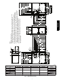
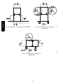
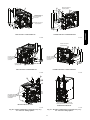
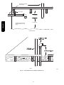
bottom of furnace is used for return air connection. See Fig. 27 for
proper orientation of roll--out shield.
Supply Air Connections
For a furnace not equipped with a cooling coil, the outlet duct shall
be provided with a removable access panel. This opening shall be
accessible when the furnace is installed and shall be of such a size
that the heat exchanger can be viewed for possible openings using
light assistance or a probe can be inserted for sampling the air
stream. The cover attachment shall prevent leaks.
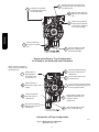
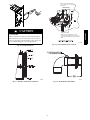
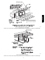
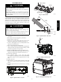
Connect supply--air duct to flanges on furnace supply--air outlet.
Bend flange upward to 90_ with wide duct pliers. See Fig. 20. The
supply--air duct must be connected to ONLY the furnace
supply--outlet--air duct flanges or air conditioning coil casing
(when used). DO NOT cut main furnace casing side to attach
supply air duct, humidifier, or other accessories. All supply--side
accessories MUST be connected to duct external to furnace main
casing.
PG95XAT
Return Air Connections
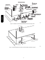
The return--air duct may be connected to bottom of the furnace.
The side of casing that faces downward may also be used for return
air connection. A combination of the bottom and downward
facing side may also be used. The upward facing side of the casing
cannot be used as a return air connection. See Fig. 26.
Bottom Return Air Inlet
These furnaces are shipped with bottom closure panel installed in
bottom return--air opening. Remove and discard this panel when
bottom return air is used. To remove bottom closure panel, perform
the following:
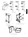
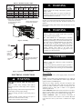
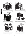
1. Tilt or raise furnace and remove 4 screws holding bottom
plate. See Fig. 22.
2. Remove bottom plate.
3. Remove bottom closure panel.
4. Reinstall bottom plate and screws.
Side Return Air Inlet
These furnaces are shipped with bottom closure panel installed in
bottom return--air opening. This panel MUST be in place when
side return air inlet(s) are used without a bottom return air inlet.
Not all horizontal furnaces are approved for side return air
connections See Fig. 26.
Filter Arrangement
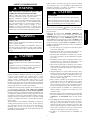
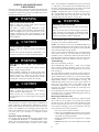
!
WARNING
Due to the relatively high pressure drops of 1--in. (25 mm) thick
after--market filter media, it is recommended that the filtration
system be designed for at least 2--in. (51 mm) thick media.
TIPS FROM CONTRACTORS: Install a media cabinet capable
of incorporating a 4--in. (102 mm) thick media filter. This allows
room for future upgrades to other IAQ devices.
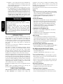
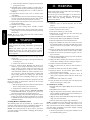
NOTICE
Design the duct system FIRST to determine how much
pressure drop may be allowed in the filter system. See the Air
Ducts section. Excessive filter pressure drop often
compromises system airflow and duct performance, causes
inadequate airflow to the furthest ends of the duct system, as
well as causes excess noise and higher than anticipated
electrical consumption.
Provide duct transitions, as required, to smoothly transition airflow
from the return duct system to the filter (or IAQ device) to the
furnace when the dimensions of the ductwork or furnace return air
opening do not match the required filter or IAQ device dimensions.
See the instructions supplied with factory--accessory duct adapters.
There are no provisions for an internal filter in these furnaces. An
external filter rack is required and is purchased separately. A field
supplied accessory air cleaner may also be used in place of the filter
rack.
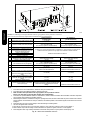
For upflow applications, the filter can be installed on either side of
the furnace, the bottom of the furnace or any combination of side
and bottom of the furnace. (See Fig. 18 and 24.)
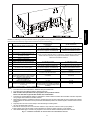
For downflow applications, the filter rack (or field supplied
accessory air cleaner) must only be connected to the bottom
opening on the furnace. (See Fig. 18 and 25.)
For horizontal applications, the filter rack (or field supplied
accessory air cleaner) can be connected to the bottom opening on
the furnace. For side return use in the horizontal position, refer to
Fig. 26. If both side and bottom openings are used in Fig. 26, each
opening used will require a filter.
A filter rack or any field supplied accessory air cleaner can also be
installed in the common return duct prior to entering the return air
opening in any orientation.
Refer to the instructions supplied with the Filter Rack or accessory
air filter for additional assembly and installation options.
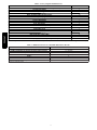
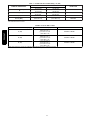
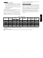
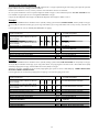
See Table 7 for recommended filter size details.
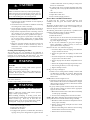
FIRE, CARBON MONOXIDE AND POISONING
HAZARD
Failure to follow this warning could result in fire, personal
injury or death.
Never operate a furnace without a filter or filtration device
installed. Never operate a furnace with filter or filtration
device access doors removed.
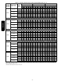
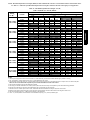
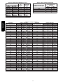
Pressure drop must be taken into account when sizing filters, filter
racks, IAQ devices, and associated system ductwork. See Table 5
for a comparison of Pressure Drop (initial/clean resistance to
airflow) versus Airflow for a variety of filter media types and sizes.
These are representative numbers. Consult the filter or IAQ device
manufacturers’ specification sheet for performance data for a
particular filter media or IAQ device.
Design the filter and associated ductwork for the best match of
pressure drop versus filter size. Best practice usually chooses filter
systems with pressure drops under 0.2 in. W.C. (50 Pa), with the
best blower electrical efficiency and system airflow performance
occurring with filter pressure drops under 0.1 in. W.C. (25 Pa).
22