1
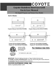
Espresso Machine
Technical Manual
Copyright Notice
The material in this document is the intellectual property of Style Café Ltd technical department. We
take every care in the preparation of this document, but no guarantee is given as to the correctness of
its contents. Our products are under continual improvement and we reserve the right to make changes
without notice.
Trademarks
All trademarks used in this manual are the sole property of their respective owner. “Stafco” is a
registered trade mark of Style Café Ltd.
Designed By Lee Rushton 2004
Stafco
Contents
1
2
3
4
5
6
7
8
9
10
11
12
13
14
15
17
18
19
20
Introduction
Machine Range
Installation
Keypad Programming
Keypad
Flow System
Group Head Flow
Pump
Old Group Head
New Group Head
Steam/Water Valve
Boiler
Elements
Sight Glass
Various
Grinder Motor
Grinder Doser
Office Wiring
Cleaning
Stafco
Intro
INTRODUCTION
This manual is intended for the machine service engineer.
The sole objective of this manual is to enable the service engineer to better understand the machines
operating principals and how to ensure that the installation and any maintenance work carried out
make the machine safe for user operation.
The manual should be kept for future use as we accept no responsibility for any damage caused by
the equipment if it is used in other ways not described in this manual or if the servicing and
maintenance guidelines are not adhered to.
We reserve the right to update any information contained in this manual without prior notice. Any
information that is updated does not mean that the previous information was inadequate.
If the machine is used incorrectly or installed in other ways not contained in this manual then any
warranties issued will become void.
The installer must check any local bylaws to ensure that the machine is fitted to meet local
regulations.
The machine is not to be operated by children or unsuitable persons.
If the machine is to be left in an un-operational state in temperatures below 0 the boiler system
should be drained to avoid any damage to the pipes or boiler.
SAFETY PRECAUTIONS
Do not tamper with any of the machines components and use only approved replacement components.
The machine should be disconnected from the mains electricity supply before removal of any covers.
Various parts of the machine do become very hot during normal use and caution should be used when
working near group heads or steam and water sections on the machine.
The machine should never be operated without a water supply connected.
It is the installers/users responsibility to ensure an adequate clean water supply to the machine and a
filter/softener should be used on all installations.
1
Stafco
Range
TECHNICAL OVERVIEW
Stafco Traditional Digital Espresso Machine
The machine range is available from the baby Office machine right up to a 3 Group Avanti raised for
take away cups. All the Stafco machines come complete with automatic fill and built in pump as well as
utilising the same components across the entire range. This means that the engineer needs to carry
less parts when servicing a Stafco espresso machine.
All our machines are supplied from our factory complete with all group handles, a backwash filter,
mains plug, drain hose, and water connection pipe in order to ease installation. You will only need to
obtain an adapter to fit from your customers mains supply to our standard 3/8 female.
Office
2 Group Inter
2 Group Avanti
1 Group Plus
Compact Avanti
2 Group Plus
3 Group Avanti
2
Stafco
Installation
The machine is connected to the mains electrical supply via a 13A plug (excluding 3 group and upgrades)
and to the main cold water supply via a flexible 3/8” stainless steal hose.
In all areas we strongly recommend the fitting of a suitable water treatment system. Where the water
supply is totally lime free (and this area is declining) a standard carbon based filter will be sufficient,
this should then be changed on a 6 month basis. In all other areas the fitting of a resin based softener
should be used, using the following table as a guideline:
Machine
1 Group Inter Plus
2 Group Inter Compact
2 Group Inter Compact Avanti
Softener Size
CTU5
Approx. Ltrs
3300
2 Group Inter Standard
2 Group Inter Plus
2 Group Inter Avanti
CTU10
7700
3 Group Avanti
3 Group Elegance
CTU18
13000
Initial Installation
On all installations where the incoming water supply pressure is above 4 bar, then the fitting of a 3 bar
pressure regulator is required, this is in order to protect the machine and the water treatment system.
Installation of the machine should be on a perfectly horizontal surface, this allows even distribution of
the coffee into the cups when using the 2 cup handle, adjustment can be carried out using the
adjustable feet of the machine.
The water supply to the machine area should be flushed through, this will remove any debris that may
be left in the pipe system from plumbing work, after complete flushing, the water supply should then be
connected to the filter system. Connect a hose to the outlet of the filter/softener and flush the unit
through until clear water flows, if using a CTU then 5 times the volume of the CTU size should be
flushed through, i.e. CTU5 = 25ltrs.
After flushing, the machine hose can then be connected to the water filter. Make sure that the water
supply is turned on, the machine can now be connected to the mains electrical supply, open the steam
knob and switch the machine on.
Upon turning the machine on, you should see the keypad lights flash once and after a few seconds the
machine will begin to auto fill. If the keypad lights start to flash during filling then this indicates that
the boiler has not filled in time (safety timeout), please switch the machine off for a moment and then
on again to resume normal filling.
After approximately 20 mins when steam starts to come out of the open steam arm, close the steam
knob and after a few more minutes the boiler will be completely up to pressure.
It is normal that during the heating up phase that water will drip from the expansion valves into the
drip tray.
3
Stafco
Programming
Start/Stop
1 Espresso
1 Cappuccino
2 Espresso
2 Cappuccino
Programming The Group
1.
Press and hold the START/STOP button on the group required.
2.
Hold the button in for approx. 8 seconds until the LED’s light up.
3.
Press the selection button for the coffee required.
4.
When the coffee in the cup has reached the required level press the button aginn.
Example of Programming 1 Cappuccino
1.
Press and hold
until LED’s light up. release
2.
Then press
when the level in the cup is right press
3.
After appro. 15 seconds all the lights on the keypad will go out and the new setting
will be
stored automatically.
Fault Conditions Indicated By The Keypad
1.
One LED flashing = Indicates that the keypad is not receiving a signal from the
flowmeter. This could be no water supply, flowmeter faulty, or group head solenoid. When this
happens the keypad will disable the selection until a signal from the flowmeter is received.
2.
All LED’s flashing = Boiler has not filled up in allowed time. Possible causes of this
could be again no water supply, inlet solenoid faulty, customer drawing hot water off whilst
boiler is trying to fill. After cause is rectified turning the machine off then on again will clear
this fault.
4
Stafco
Keypad
Keypad Definition
We only use one type of keypad throughout the entire range of Stafco machines, because the
keypad can be factory programmed into serving several modes of operation, please specify exactly
the type of machine and if the keypad is for left or right side operation!
Keypad Input/Outputs
CN1
CN2
CN3
CN5
CN6
2 wire connection to the level probe on the boiler.
Used for communication between the keypad and a PC using our interface.
Can be used to connect an external tea water switch (not recommended).
Main power in and out.
Used for turbine/flowmeter
CN1
CN3
CN5
CN2
CN6
CN5
SUPPLY AC
SUPPLY AC
COM OUT
GROUP SOLENOID
PUMP MOTOR
FILLING SOLENOID
RELAY 3 TEA/ELEMENT
5
CN6
CN3
TEA PAD
TEA PAD
LED –
LED +
+21 VDC
SIGNAL PULSE
0 VDC
Stafco
Flow
1
2
3
4
5
6
7
8
9
Water Softener
Pump
Fill Solenoid
Turbine (flow meter)
Pressure Switch
Element
Heat Exchanger
Boiler
Pressure Gauge
10
11
12
13
14
15
16
17
Anti-vac Valve
Level Probe
Safety Valve (1.6 bar)
Group Solenoid
Group Handle
Steam Valve
Group Head
Hot Water Valve
15
17
16
16
14
14
13
13
10
1
0
11
12
9
2
3
6
5
7
7
8
MAINS
3
4
WATE R
1
4
2
6
Stafco
Group Head
1
2
4
3
5
6
Old Style Group Head
Brass Injector and Stem
1
2
3
4
5
6
7
8
9
10
11
Injector Filter
Group Head Plug
Flow Reducer
Injector
Group Diffuser
Injector Stem
Group Solenoid
Solenoid Coil
Shower
Group Head Gasket
Access Screw
New Style Group Head
Teflon Injector and
Stem
C50020000 Flow Reducer 3.5mm
7
10
7
9
8
11
Stafco
Pump
C70000000 Filter Body
C70000009 Filter
*
C70000001 Filter Support
C30000240 3/8” Fitting
C650000010
Retention Valve
C60000020 Motor
C60000032 Pump Inc Filter
C50100000 Motor Damper
*
It is recommended that this filter is either
cleaned or changed during a service due to
dirt/scale build up.
8
Stafco
Old Group Head
C30200030 Group Head Plug
C50010040 Teflon Gasket
C70000009 Injector Filter
C30200050 Injector
C30200020 Injector Stem
C50020000
Flow Reducer 3.5mm
C50000010 Chassis Gasket
C30200010 Group Head
C50000100 Valve O Rings
C30200040 Group Diffuser
C60000112 3 Way Valve
C75000010 Shower
C75000081 Group Gasket
C75000030 7g Filter Basket
C30000040 Exhaust Diffuser
C75000040 14g Filter Basket
C75000120 Filter Basket Spring
C75000020 Blind Filter Basket
C75000110 Filter Holder
C75000105 Filter Handle Black
C75000100 Filter Handle Red
C75000060 2 Cup Spout
9
C75000050 1 Cup Spout
Stafco
New Group Head
C30200035 Group Head Plug
C50010040 Teflon Gasket
C70000009 Injector Filter
C30200060 Teflon Injector
C50030000 Teflon Stem Supportr
30200025 Teflon Injector Stem
C25091250 Allen Screw 6 x 10
C50020000
Flow Reducer 3.5mm
C50000010 Chassis Gasket
C30200010 Group Head
C50000100 Valve O Rings
C30200040 Group Diffuser
C60000112 3 Way Valve
C75000010 Shower
C75000081 Group Gasket
C75000030 7g Filter Basket
C30000040 Exhaust Diffuser
C75000040 14g Filter Basket
C75000120 Filter Basket Spring
C75000020 Blind Filter Basket
C75000110 Filter Holder
C75000105 Filter Handle Black
C75000100 Filter Handle Red
C75000060 2 Cup Spout
C75000050 1 Cup Spout
10
Stafco
Steam/Water Valve
C30370110 Split Pin
C40000020 Knob
C15000325 Valve
Steam C30370130
Water C30370120
C30370076 Spring
C30370100 Washer
C30370077 Washer
C30370075 Seal
High Group
C35010075 Arm Inox
Standard Steam Arm
C35010050 Arm Inox
C30370150 Seal
C30000010 Nozzle Inox
Complete Valve With
Steam Arm C15000322
C30370080 Water Pipe
11
Stafco
Boiler
C65000110 Security Valve
C60100040 Level Probe Complete
C25000003 Washer with Earth Connection
C30000200 ½ x ½ Exchanger Elow
C30000110 3 Way ¼ x ¼ x 1/8
C30000100 2 Way ¼ x 1/8
C20010020 Teflon Gasket ¼
C50010030
Element Gasket
C50010020 Teflon Gasket ¼
C30000210 Fitting ½ x ½ x ¼
C50010010 Teflon Gasket ½ x 5mm
C30000220 Injector
12
Stafco
Elements
C38027000
2 Group Element
2700W
C38045000
2 Group Element
4500W
3700W
C38040000
3 Group Element
6000W
C38060000
3-4 Group Element
C38014502
1 Group Element
1450W
C38025001
2 Group Compact Element
2500W
1200W
13
C38012000
Office Element
Stafco
Sight Glass
C20010020 Level Support
C65000200 Anti Vac Valve
C35902000 Sight Glass
M
A
X
C30100040 Gland Chrome
C30100050 V Washer
C50000115 O Ring
C30100060 Brass Level Housing
C50010050
Teflon Gasket 3/8
M
I
N
C30000215 Elbow ¼ x ¼
C70300055 Gauge Plastic
C15000310 Stop Tap
14
Stafco
C60000000
Pressure Switch
Various
C60000007
Pressure Switch
C60100050
Flowmeter - Turbine
1/L
1
C60102030
Turbine Top
2/T
2
4/A
2
3/A
1
C60102020
Turbine O Ring
C60102010
Turbine Impeller
C60800100
Solid State Relay
C60000040
Office Pump
15
Stafco
Various
0
1
C60000060
1 way small gauge
C60000065
1 way large gauge
C60100101
Level Control Box
C60100020
Keypad With Level Control
C60900000
Mains Switch 16A
C60000050
2 way large gauge
C60100200
Level Control Box
With Element Protection
C60900043
Black Switch
C60100250
New Level Probe Cable
C60100030
7 Way Keypad Connector
C60900002
Mains Switch 20A
C60900035
Red Neon Switch
C60901000
Element Neon
C40000040
Mains Switch Knob
16
Stafco
Grinder Motor
C0000560 Adjusting Ring
C0001150 Lock Release
C0000590 Upper Grindstone
C0000770 Spring
C0000550 Grindstone Holder
C0000710 Nut
C0000720 Washer
C0000600 Lower Grindstone
C0000620 Lower Grindstone Holder
C0001210 Mounting Plate
C00000880 Nut
C0000540
12mf Capacitor
17
C00001200 Motor
Stafco
Grinder Dosing Unit
C0000430 Lid
C0000400 Lid
C0000470 Microswitch
C0000440 Switch Assembley
C0000450 Auto Stop Flap
C0001140 Supplement Ring
C0000250 Weight Adjust Screw
C0000790 Square Washer
C0000660 M5 x 18 Screw
C0000090 Doser Ring
C0000070 Doser Glass 600g
C0000160 Upper Star Assembly
C0000290 Divider Plate
C0000280 Weight Adjust Spring
C0000240 Nut M4
C0000150 Lower Star
C0000190 3.5 Screw
C0000180 Tamper Top
C0000100
Doser Bottom Ring
C0000140 Doser Base
C0000260
Return Spring
C0000310
C0000300
C0000270
C0000320
Dosing Lever
C0000230
Index Cog
C0000130 M6 Screw
C0000120 Clamp
C0000200
Tamper Base
18
Stafco
Office Wiring
1
N Supply
2
L Supply
3
Fill Solenoid
4
Pump
5
Element
RL-10
Fault LED
7
Level Probe
8
Probe Earth
9
RED
7
Fault LED
WHT
10
WHT
8
10
Fault LED
G/Y
9
Level Probe
Heater Light
(Underside View)
Boiler
RL-10
Control Box
5
BLK
Trip
BLK
Pressure
Switch
Element
W/B
On/Off
Switch
Live
BRN
WHT
2
W/R
4
Pump
Fill Solenoid
Neutral
BLU
W/B
1
3
WHT
W/B
WHT
Group
Head
Switch
BRN = Brown
BLU = Blue
WHT = White
BLK = Black
W/B = White/Blue
W/R = White/Red
G/Y = Green/Yellow
19
WHT
Group Head Solenoid
Stafco
Cleaning
DAILY END OF DAY
Group Head
!
!
Blind Filter
Remove the filter basket from the group handle and
fit the blind filter.
Lock the handle into the group head and press the
star key on the keypad after 10 seconds press the
star key again to stop the group, repeat this
operation 6 times and empty the group handle
between operations.
WEEKLY OR TWICE IF BUSY
!
!
!
Group Handle
!
!
Steam Arm
STEAM ARM CARE
!
!
!
!
Gasket
With the blind filter in the group handle add one
teaspoon of Espresso Cleaner into the blind filter.
Secure the group handle into the group head and
activate the pump for 20 seconds.
Stop the pump and repeat 3 times with a 5 second
gap.
Remove the group handle and run water through the
group for 10 seconds.
Replace the group handle and operate the pump for
10 seconds, repeat this step 3 times, empty handle
between operations.
!
During the course of the day after using any
product on the steam arm wipe down with a soft
damp cloth.
After use blast a bit of steam through to clear the
arm.
DO NOT leave the steam arm standing in any sort
of liquid.
End of day remove the steam nozzle from the end
of the arm and soak the nozzle in a cup of hot water
overnight.
If the nozzle gets blocked clear the 4 holes out
with a paper clip.
Steam Nozzle
20
Style Café Ltd
Glyde Works, Byron Road
Colne, Lancashire, BB8 0BQ
Tel 01282 869641 Fax 01282 869616
www.stylecafe.co.uk