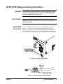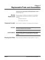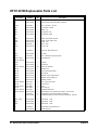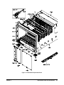
1
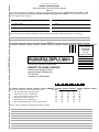
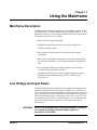
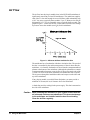
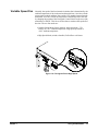
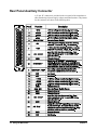
Contents
HP E1401B User’s Guide and Service Manual
Edition 3
Warranty ....................................................................................................................... 3
Safety Symbols ............................................................................................................. 4
WARNINGS ................................................................................................................. 4
Declaration of Conformity............................................................................................ 5
Reader Comment Sheet ................................................................................................ 7
Chapter 1
Using the Mainframe ..................................................................................................... 9
Mainframe Description ................................................................................................. 9
Line Voltage and Input Power ...................................................................................... 9
Air Flow ...................................................................................................................... 10
Variable Speed Fan ............................................................................................. 11
Rear Panel Auxiliary Connector ................................................................................. 12
Remote Standby Switch ...................................................................................... 14
Installing the Power Line Fuse ................................................................................... 15
Power Cords................................................................................................................ 16
HP E1401B Safety Grounding Information................................................................ 17
Grounding Procedure .......................................................................................... 17
Chapter 2
Replaceable Parts and Assemblies ............................................................................. 19
Module Replacement ........................................................................................... 19
Component Locator ............................................................................................. 19
Cleaning Fan Filters ............................................................................................ 19
HP E1401B Replaceable Parts List ............................................................................ 20
Appendix A
HP E1401B Specifications ........................................................................................... 25
Index ................................................................................................................................ 29
Contents
1
Notes:
2
Contents
Certification
Hewlett-Packard Company certifies that this product met its published specifications at the time of shipment from the factory. HewlettPackard further certifies that its calibration measurements are traceable to the United States National Institute of Standards and
Technology (formerly National Bureau of Standards), to the extent allowed by that organization’s calibration facility, and to the
calibration facilities of other International Standards Organization members.
Warranty
This Hewlett-Packard product is warranted against defects in materials and workmanship for a period of three years from date of shipment.
Duration and conditions of warranty for this product may be superseded when the product is integrated into (becomes a part of) other HP
products. During the warranty period, Hewlett-Packard Company will, at its option, either repair or replace products which prove to be
defective.
For warranty service or repair, this product must be returned to a service facility designated by Hewlett-Packard (HP). Buyer shall prepay
shipping charges to HP and HP shall pay shipping charges to return the product to Buyer. However, Buyer shall pay all shipping charges,
duties, and taxes for products returned to HP from another country
HP warrants that its software and firmware designated by HP for use with a product will execute its programming instructions when
properly installed on that product. HP does not warrant that the operation of the product, or software, or firmware will be uninterrupted
or error free.
Limitation Of Warranty
The foregoing warranty shall not apply to defects resulting from improper or inadequate maintenance by Buyer, Buyer-supplied pr oducts
or interfacing, unauthorized modification or misuse, operation outside of the environmental specifications for the product, or improper
site preparation or maintenance.
The design and implementation of any circuit on this product is the sole responsibility of the Buyer. HP does not warrant the Buyer’s
circuitry or malfunctions of HP products that result from the Buyer’s circuitry. In addition, HP does not warrant any damage that occurs
as a result of the Buyer’s circuit or any defects that result from Buyer-supplied products.
NO OTHER WARRANTY IS EXPRESSED OR IMPLIED. HP SPECIFICALLY DISCLAIMS THE IMPLIED WARRANTIES OF
MERCHANTABILITY AND FITNESS FOR A PARTICULAR PURPOSE.
Exclusive Remedies
THE REMEDIES PROVIDED HEREIN ARE BUYER’S SOLE AND EXCLUSIVE REMEDIES. HP SHALL NOT BE LIABLE FOR
ANY DIRECT, INDIRECT, SPECIAL, INCIDENTAL, OR CONSEQUENTIAL DAMAGES, WHETHER BASED ON CONTRACT,
TORT, OR ANY OTHER LEGAL THEORY.
Notice
The information contained in this document is subject to change without notice. HEWLETT-PACKARD (HP) MAKES NO
WARRANTY OF ANY KIND WITH REGARD TO THIS MATERIAL, INCLUDING, BUT NOT LIMITED TO, THE IMPLIED
WARRANTIES OF MERCHANTABILITY AND FITNESS FOR A PARTICULAR PURPOSE. HP shall not be liable for errors
contained herein or for incidental or consequential damages in connection with the furnishing, performance or use of this material. This
document contains proprietary information which is protected by copyright. All rights are reserved. No part of this document may be
photocopied, reproduced, or translated to another language without the prior written consent of Hewlett-Packard Company. HP assumes
no responsibility for the use or reliability of its software on equipment that is not furnished by HP.
U.S. Government Restricted Rights
The Software and Documentation have been developed entirely at private expense. They are delivered and licensed as "commercial
computer software" as defined in DFARS 252.227- 7013 (Oct 1988), DFARS 252.211-7015 (May 1991) or DFARS 252.227-7014
(June 1995), as a "commercial item" as defined in FAR 2.101(a), or as "Restricted computer software" as defined in FAR 52.227-19
(June 1987)(or any equivalent agency regulation or contract clause), whichever is applicable. You have only those rights provided for
such Software and Documentation by the applicable FAR or DFARS clause or the HP standard software agreement for the product
involved
HP E1401B User’s Guide and Service Manual
Edition 3
Copyright © 1997 Hewlett-Packard Company. All Rights Reserved.
3
Documentation History
All Editions and Updates of this manual and their creation date are listed below. The first Edition of the manual is Edition 1. The Edition
number increments by 1 whenever the manual is revised. Updates, which are issued between Editions, contain replacement pages to
correct or add additional information to the current Edition of the manual. Whenever a new Edition is created, it will contain all of the
Update information for the previous Edition. Each new Edition or Update also includes a revised copy of this documentation hist ory page.
Edition 1 . . . . . . . . . . . . . . . . . . . . . . . . . . . . . . . . . . . . . . . . . . . . . January 1995
Edition 2 . . . . . . . . . . . . . . . . . . . . . . . . . . . . . . . . . . . . . . . . . . . . . August 1995
Edition 3 . . . . . . . . . . . . . . . . . . . . . . . . . . . . . . . . . . . . . . . . . . . . . . March 1997
Safety Symbols
Instruction manual symbol affixed to
product. Indicates that the user must refer to
the manual for specific WARNING or
CAUTION information to avoid personal
injury or damage to the product.
Alternating current (AC)
Direct current (DC).
Indicates hazardous voltages.
Indicates the field wiring terminal that must
be connected to earth ground before
operating the equipmentÅprotects against
electrical shock in case of fault.
or
Frame or chassis ground terminal—typically
connects to the equipment's metal frame.
Calls attention to a procedure, practice, or
WARNING condition that could cause bodily injury or
death.
Calls attention to a procedure, practice, or
CAUTION condition that could possibly cause damage to
equipment or permanent loss of data.
WARNINGS
The following general safety precautions must be observed during all phases of operation, service, and repair of this product. Failure to
comply with these precautions or with specific warnings elsewhere in this manual violates safety standards of design, manufacture, and
intended use of the product. Hewlett-Packard Company assumes no liability for the customer's failure to comply with these requirements.
Ground the equipment: For Safety Class 1 equipment (equipment having a protective earth terminal), an uninterruptible safety earth
ground must be provided from the mains power source to the product input wiring terminals or supplied power cable.
DO NOT operate the product in an explosive atmosphere or in the presence of flammable gases or fumes.
For continued protection against fire, replace the line fuse(s) only with fuse(s) of the same voltage and current rating and type. DO NOT
use repaired fuses or short-circuited fuse holders.
Keep away from live circuits: Operating personnel must not remove equipment covers or shields. Procedures involving the removal of
covers or shields are for use by service-trained personnel only. Under certain conditions, dangerous voltages may exist even with the
equipment switched off. To avoid dangerous electrical shock, DO NOT perform procedures involving cover or shield removal unless you
are qualified to do so.
DO NOT operate damaged equipment: Whenever it is possible that the safety protection features built into this product have been
impaired, either through physical damage, excessive moisture, or any other reason, REMOVE POWER and do not use the product until
safe operation can be verified by service-trained personnel. If necessary, return the product to a Hewlett-Packard Sales and Service Office
for service and repair to ensure that safety features are maintained.
DO NOT service or adjust alone: Do not attempt internal service or adjustment unless another person, capable of rendering first aid and
resuscitation, is present.
DO NOT substitute parts or modify equipment: Because of the danger of introducing additional hazards, do not install substitute parts
or perform any unauthorized modification to the product. Return the product to a Hewlett-Packard Sales and Service Office for service
and repair to ensure that safety features are maintained.
4
Declaration of Conformity
according to ISO/IEC Guide 22 and EN 45014
Manufacturer’s Name:
Hewlett-Packard Company
Loveland Manufacturing Center
Manufacturer’s Address:
815 14th Street S.W.
Loveland, Colorado 80537
declares, that the product:
Product Name:
C-Size High Power VXI Mainframe
Model Number:
HP E1401B
Product Options:
All
conforms to the following Product Specifications:
Safety:
IEC 1010-1 (1990) Incl. Amend 1 (1992)/EN61010-1 (1993)
CSA C22.2 #1010.1 (1992)
UL 3111
EMC:
CISPR 11:1990/EN55011 (1991): Group1 Class A
IEC1000-3-2:1995/EN61000-3-2 (1995): Class A
IEC 801-2:1991/EN50082-1 (1992): 4kVCD, 8kVAD
IEC 801-3:1984/EN50082-1 (1992): 3 V/m
IEC 801-4:1988/EN50082-1 (1992): 1 kV Power Line, 0.5 kV Signal Lines
ENV50141: 1993/prEN50082-1 (1995): 3 Vrms
ENV50142: 1994/prEN50082-1 (1995): 1 kVCM, 0.5 kVDM
IEC1000-4-8:1993/prEN50082-1 (1995): 3 A/m
EN61000-4-11: 1994/prEN50082-1 (1995): 30%, 10ms 60%, 100 ms
Supplementary Information: The product herewith complies with the requirements of the Low Voltage Directive
73/23/EEC and the EMC Directive 89/336/EEC (inclusive 93/68/EEC) and carries the "CE" marking accordingly.
November 6, 1995
Jim White, QA Manager
European Contact: Your local Hewlett-Packard Sales and Service Office or Hewlett-Packard GmbH,
Department HQ-TRE, Herrenberger Straße 130, D-71034 Böblingen, Germany (FAX +49-7031-14-3143)
5
Notes:
6
Please fold and tape for mailing
Reader Comment Sheet
HP E1401B User’s Guide and Service Manual
Edition 3
You can help us improve our manuals by sharing your comments and suggestions. In appreciation of your time, we will
enter you in a quarterly drawing for a Hewlett-Packard Palmtop Personal Computer (U.S. government employees
are not eligible for the drawing).
Your Name
City, State/Province
Company Name
Country
Job Title
Zip/Postal Code
Address
Telephone Number with Area Code
Please list the system controller, operating system, programming language, and plug-in modules you are using.
fold here
cut along this line
NO POSTAGE
NECESSARY
IF MAILED
IN THE
UNITED STATES
BUSINESS REPLY MAIL
FIRST CLASS
PERMIT NO. 37
LOVELAND, CO
POSTAGE WILL BE PAID BY ADDRESSEE
HEWLETT-PACKARD COMPANY
Measurement Systems Division
Learning Products Department
P.O. Box 301
Loveland, CO 80539-9984
fold here
Please pencil-in one circle for each statement below:
• The documentation is well organized.
• Instructions are easy to understand.
• The documentation is clearly written.
• Examples are clear and useful.
• Illustrations are clear and helpful.
• The documentation meets my overall expectations.
Please write any comments or suggestions below–be specific.
Disagree
O
O
O
O
O
O
Agree
O
O
O
O
O
O
O
O
O
O
O
O
O
O
O
O
O
O
O
O
O
O
O
O
Chapter 1
Using the Mainframe
Mainframe Description
The HP E1401B mainframe is designed in full compliance with the VXIbus
specification (Rev. 1.4) and VMEbus system specification (Rev. C.1). The
mainframe contains 13 slots for plug-in modules and can be rack mounted
in either the forward or reverse position.
• Improved Power Supply Reliability
• Solid state automatic bus grant sensing to bypass empty slots.
• Variable speed fan cooling.
• Rear mounted 25-pin D connector for auxiliary power supply
monitoring.
• Easy replacement of major components - most can be replaced from
the rear of the mainframe, even while the mainframe is mounted in a
rack.
• Seven standard VXIbus power supply voltages - all overvoltage,
overcurrent, and temperature protected.
• Maximum Usable Power (total power supply output power before
thermal protection shutdown): 900 W @25°C, 800W @ 40°C,
650 W @ 55°C.
Line Voltage and Input Power
The HP E1401B mainframe includes a power supply which automatically
adjusts for standard nominal line voltages of 100/120 VAC and 220/240
VAC, and nominal power line frequencies of 50 Hz and 60 Hz. The power
supply has a power factor corrected input section and thus can be powered
from any nominal line input over the range of 100 VAC to 240 VAC. The
power supply can also be powered from a 400 Hz AC line frequency or DC
power line voltages. Refer to Appendix A for complete input power
specifications.
WARNING
Chapter 1
Refer to “HP E1401B Safety Grounding Information” on page 17
for complete grounding information when power line
frequencies exceed 66Hz.
Using the Mainframe
9
Air Flow
The air flow into the plug-in module slots in the HP E1401B mainframe is
significantly more than previous HP mainframes. The mainframe supplies
each of the 13 slots with enough air to cool 60 Watts while maintaining only
a 10°C rise across a typically dense module. Up to 75 Watts per slot may be
dissipated if a 15°C rise is acceptable across a typically dense module. The
graph of Figure 1-1 shows the air flow volume (liters/second) versus change
in pressure across the module (mm H2O) for the mainframe.
Figure 1-1. Minimum Airflow Available Per Slot
The mainframe has a fan chamber with three circulation fans. The speed of
the fans is controlled by the ambient temperature of the air drawn into the
mainframe. Air from the fan chamber is forced into the compartmentalized
plenum at the bottom of the mainframe. Although the plenum does contain
a compartmentalized structure, some air flow is always present in each of the
13 slots even if one of the three mainframe circulation fans fails to operate.
The air passes through the installed modules and escapes out the sides and
top of the mainframe.
If any plug-in module exceeds 40 Watts dissipation, you must provide a
minimum of 20 mm (0.8 in) of clearance above the mainframe.
A fourth fan provides cooling for the power supply. This fan is mounted on
the side of the mainframe.
Caution
10
Using the Mainframe
When installing the mainframe in your system, ensure that the
air inlets and outlets are not obstructed. This prevents damage
to the mainframe and installed modules due to overheating.
Clean the air filter regularly.
Chapter 1
Variable Speed Fan
Normally, the speed of the four internal circulation fans is determined by the
ambient temperature of the air drawn into the mainframe. One fan cools the
power supply module and three fans cool the VXI modules inserted into the
mainframe. You can override the temperature-controlled speed of the fans
by changing the position of the Fan Speed Control Switch on the rear of the
mainframe to “HIGH”. This forces all four fans to remain at full speed all of
the time. The two fan modes are:
• Variable Speed Mode (factory default): Quiet operation (~75%
airflow) at <30°C ambient temperature. High speed operation at
>40°C ambient temperature.
• High Speed Mode (switch selectable): Full airflow at all times.
Figure 1-2. Forcing the Fan to High Speed
Chapter 1
Using the Mainframe
11
Rear Panel Auxiliary Connector
A 25-pin “D” connector is provided on the rear panel of the mainframe to
allow monitoring of power supply voltages and other functions. The pinouts
for this connector are shown in the following table.
12
Using the Mainframe
Chapter 1
+5V
Chapter 1
The +5 volt output lets you power external TTL circuitry if required. The
maximum current allowed from this supply is 1.0A.
+12V
The +12 volt output lets you power a battery charging circuit to provide a
source for the +5V STDBY input. The maximum current allowed from this
supply is 1.0A.
+5V STDBY
This provides an input to the mainframe backplane for a +5 volt standby
power source. This may be from a separate battery or power supply. The
maximum current input allowed is 1.0A. This means that all of the standby
circuitry in all of the modules mounted in the mainframe can draw a total of
1.0A when active.
SYSRESET*
This pin provides an extension of the backplane SYSRESET* signal. It can
be used to monitor for SYSRESET* or to send SYSRESET* to the
backplane. Shorting this line to ground inputs a SYSRESET* signal to the
system. If you use any extension cable out of the 25-pin D connector on the
mainframe rear panel, make certain that you do not violate VXI backplane
electrical specifications (i.e. keep the cable as short as possible, or buffer the
signal, etc.).
ACFAIL*
This pin lets you monitor the ACFAIL* signal from the backplane. Since
this pin is connected directly to the backplane, do not violate VXI backplane
electrical specifications (i.e. keep the cable as short as possible, or buffer the
signal, etc.).
EXHAUST_TEMP
This pin provides an analog output that is proportional to the power supply
exhaust temperature. Using this circuit, you can monitor the actual
temperature of the power supply exhaust temperature to receive a warning
signal that the mainframe is running under abnormal conditions. This output
provides 0Vdc at 0°C, with a rise of 10mV per degree centigrade when
referenced to chassis ground.
Using the Mainframe
13
Remote Standby
Switch
The remote standby switch connection is provided to let you turn the
mainframe ON or put it in STANDBY mode remotely. These two
connections are wired in parallel with the front panel ON/STANDBY
switch. This means that the front panel switch must be in STANDBY
position for the remote switch to function correctly.
Figure 1-3. Remote Standby Switch Wiring
If you wish to completely disable the front panel switch, you can remove
R93 (a surface mount, zero-Ohm resistor) on the back of the backplane PCA.
Figure 1-4 shows the location of this resistor. Once R93 is removed, the only
way to control power is through a switch connected to pins 5 and 18 of the
25-pin D connector on the rear panel of the mainframe. To access the
interface board, remove the power supply.
Figure 1-4. Location of R93 Surface Mount Resistor
14
Using the Mainframe
Chapter 1
Installing the Power Line Fuse
The mainframe is shipped with a 15A fast blow (15AF) fuse (HP Part
Number 2110-0054) already installed. This fuse is suitable for all line
voltages. Figure 1-5 shows how to replace the fuse if necessary.
Figure 1-5. Replacing the Power Line Fuse
WARNING
For continued protection against fire hazard, replace fuse only
with fuse of specified type and current rating.
AVERTISSMENT Pour ne pas compromettre la protection contra le risque
d’incendie, remplacer le fusible par un fusible de mêmes type et
courant nominal.
Chapter 1
Using the Mainframe
15
Power Cords
Table 1-1 shows the power cords and their Hewlett-Packard part numbers.
Table 1-1. Power Cords for the HP E1401B
Country
U.K.
Part Number
Volts
Rated Amps
Type
8120-5392
250 VAC
10 A
Right Angle Connector
Australia
8120-5393
250 VAC
10 A
Right Angle Connector
Europe
8120-5394
250 VAC
10 A
Right Angle Connector
U.S./Canada*
8120-5395
125 VAC
13 A
Right Angle Connector
Switzerland
8120-5397
250 VAC
10 A
Right Angle Connector
Denmark
8120-5398
250 VAC
10 A
Right Angle Connector
Japan
8120-5400
125 VAC
15 A
Right Angle Connector
Power Cords supplied by HP have polarities matched to the power input socket on the instrument:
L = Line or Active Conductor (also called “live” or “hot”), N = Neutral or identified conductor,
E = Earth or safety Ground
* CSA Certification includes only this power cord.
Note
WARNING
These are special high power cords. Make certain that any replacement
cord is capable of handling the indicated loads.
For protection from electric shock hazard, power cord ground must
not be defeated. The front power switch on this instrument does not
disconnect all power from internal circuits. In case of emergency, the
operator may need to disconnect the power to this mainframe. Do not
block the operator’s access to the power cord, or (if installed in a
rack) to the circuit breaker which supplies power to the mainframe.
If a remote standby switch is connected to the mainframe by way of
the rear panel 25-pin Sub-D connector, then the operator may not be
able to turn this unit off by using the front panel switch. Notify the
operator of the location of the disconnect device (either the power
cord or a circuit breaker) for this mainframe.
AVERTISSMENT Pour ne pas compromettre la protection contre le choc électrique, ne
pas couper le circuit de continuité des masses de la fiche.
L’interrupteur avant de cet appariel ne coupe pas la totalité de
l’alimentation des circuits internes. En cas d’urgence, l’utilisateur
peut devoir debrancher cet appareil. Ne pas bloquer l’accès au
cordon d’alimentation ou (si l’appareil est installé sur un chassis) au
disjoncteur alimentant l’appareil.
Si un interrupteur de secours a distance est branche a cet appariel au
moyen d’un connecteur Sub D a 25 broches du panneau arriere, il est
possible que l’utilisateur n’arrive pas a mettre l’appareil hors tension
au moyen de l’interrupteur frontal. Avisez l’utilisateur de
‘emplacement du dispositif de sectionnement (cordon ou disjoncteur)
de l’appareil.
16
Using the Mainframe
Chapter 1
HP E1401B Safety Grounding Information
WARNING
For protection from electrical shock when operating at mains
frequencies greater than 66 Hz, connect the chassis ground
terminal to permanent earth ground.
AVERTISSMENT Risque de Choch électrique. Si la fréquence du secteur est
supérieure à 66 Hz, relier la borne de masse du chassis à une
prise de terre fixe.
Grounding
Procedure
Connect a 16 AWG (1.3 mm or larger) wire to the PEM nut shown in
Figure 1-6. The wire must be green with a yellow stripe or bare (no
insulation). Use an M4 x 10 screw, grounding lug, and toothed washers
(or toothed lug) as shown in Figure 1-7. Securely attach the other end of the
wire to a permanent earth ground using toothed washers or a toothed lug.
Figure 1-6. Grounding Connection
Figure 1-7. Grounding Screw, Toothed Washers
Chapter 1
Using the Mainframe
17
Notes:
18
Using the Mainframe
Chapter 1
Chapter 2
Replaceable Parts and Assemblies
There are no user sevicable parts in the HP E1401B. Repair is limited to
replacing the power supply module, the backplane module, or other
mechanical parts only.
Module
Replacement
The power supply is available on an exchange basis. The backplane
assembly should be replaced and not repaired (no exchange on the
backplane).
-- Backplane: E1401-66511
-- Power Supply: E1401-69202
Component Locator
Refer to Figures 2-1 through 2-3 for component locator information.
WARNING
There are no user servicable parts inside. Refer repair and
servicing to trained service personnel.
AVERTISSEMENT
Ne contient pas d’élément que l’utilisateur puisse réparer.
Confier les réparations et la maintenance à un technicien
qualifié.
Cleaning Fan Filters
Chapter 2
Remove and clean the mainframe’s fan filter regularly (see Figure 2-3).
Replaceable Parts and Assemblies
19
HP E1401B Replaceable Parts List
Reference
Designator
20
HP Part
Number
Total
Qty.
A1
E1401-66511
1
PC Backplane Assembly
A2
E1401-69202
1
Power Supply; Power-650 Watts; 8 Outputs
B1-B4
3160-0864
4
Fan - Tubeaxial - 12 VDC
BZL1
E1401-04306
1
Front Bezel - Bottom
BZL2
E1401-04304
1
Bezel - Top
BZL3
E1401-04301
1
Front Bezel - Left
BZL4
E1401-04302
1
Front Bezel - Right
CBL1
E1401-61611
1
Cable - Back Plane Interface
CBL2
E1401-61612
1
Cable - Power Switch LED
CBL3
E1401-61610
1
Cable - Fan
CR1
1990-1027
1
LED - Lamp
CVR1
E1401-04110
1
Cover - Top
F1
2110-0054
1
Fuse 15A, 250V NTD FE UL
Description
MP2
E1401-04603
1
Air Filter
MP94
1400-1502
1
Clip - LED Mounting Polypropylene
MP95 - MP97
MP100 - MP102
E1401-81206
6
Horizontal Rail
MP98
E1401-00102
1
Chassis
MP99
E1401-04602
1
Air Plenum
MP103 - MP128
E1401-41202
26
Guide, PC Extractor
MP129
E1401-01211
1
Bracket, Fan
MP130
E1401-00203
1
Fan Carrier (Blank Panel)
MP131
E1401-00204
1
Rear Panel
MP132
E1401-01212
1
Bracket, Power Supply Bottom
MP133
E1401-01213
1
Bracket, Power Supply Top
MP134
E1401-01215
1
Bracket, Air Filter
MP135 - MP136
5001-0543
2
Trim - Side Front Frame
MP137
5021-8411
1
Frame Front
MP138 - MP141
5041-8801
4
Foot
MP142
5041-8802
1
Trim Strip Top
MP143 - MP146
5041-8821
4
Stand-Off Rear Panel
MP149 - MP150
E1401-81205
1494-0075
E1401-21200
2
2
2
Mounting Rail, Front (uses E1401-21200; 1 per front rail)
Tapped Strip (mounts inside MP97 and MP102)
Tapped Strip Non-symmetric (mounts inside MP149 - MP150)
PNL2 - PNL4
E1400-00209
3
Filler Panel - 1 Slot
PNL5
E1400-00203
1
Filler Panel - 3 Slot
PNL6
E1400-00204
1
Filler Panel - 7 Slot
X1
2110-0565
E1401-00210
1
1
Fuseholder Cap 15A Max for UL
EMI Spring Clip
Replaceable Parts and Assemblies
Chapter 2
Figure 2-1. Mainframe Replaceable Parts
Chapter 2
Replaceable Parts and Assemblies
21
Figure 2-2. Power Supply and Rear Panel Replaceable Parts
22
Replaceable Parts and Assemblies
Chapter 2
Figure 2-3. Fan Assembly and Rear Panel Replaceable Parts
Chapter 2
Replaceable Parts and Assemblies
23
Notes:
24
Replaceable Parts and Assemblies
Chapter 2
Appendix A
HP E1401B Specifications
The HP E1401B High-Power mainframes are 100% compatible with
VXIbus specification revision 1.4.
Overall Mainframe Size
Mainframe Weight
HP E1401B: 22 Kg (48.5 lbs) with no modules installed.
Module Size
Thirteen (13) C-Size slots. The mainframes also accept A- or B- Size
modules using the optional HP E1403 Module Carrier.
Input Power
50 - 60 Hz Input Power:
Automatic Voltage Ranging, nominal range: 100 - 240 Vac ±10%
Nominal Frequency Range:50 - 60 Hz ±10%
400 Hz Input Power:
Nominal Voltage Range: 100 - 120 VAC ±10%
Nominal Frequency: 400 Hz ±10%
DC Input Power:
Input Voltage Range: 100 VDC minimum - 370 VDC maximum
General Power Supply
Power Factor Corrected
Power Switch: On/Standby with lighted indicator in front
Rear panel connection allows remote operation.
Inrush Current: 40A max
Designed to meet EN-60555-2
Socket for detachable line cord: IEC 320 "HOT"
Chassis ground tap on rear panel: M4 x 0.7 threaded insert.
Fuse:
Appendix A
Voltage
Maximum Current
Fuse
100Vac
15A
15AF
120Vac
12A
15AF
220-240Vac
8A
15AF
HP E1401B Specifications
25
Power Supply Outputs
DC Output
Voltage
Peak DC Output
Current (*IMP)
40°C
55°C
P-P Dynamic
Current (**IMD)
CD Current Limit
(supply shuts down)
+5V
65A
60A
9.0A
70 - 80A
+12V
14A
12A
2.5A
14 - 18A
-12V
14A
12A
2.5A
14 - 18A
+24V
14A
12A
5.0A
15 - 19A
-24V
12A
10A
5.0A
12 - 16A
-5.2V
65A
60A
8.5A
70 - 80A
-2V
35A
30A
4.5A
35 - 41A
* IMP = Rated mainframe peak DC output current as defined by the VXIbus Specification.
** IMD = Rated mainframe peak-to-peak dynamic current as defined in the VXIbus
Specification by a current vs. frequency curve.
VXI Ripple/Noise*
DC Output
Voltage
Allowed Variation
Max. DC Load
Ripple/Noise
Max. Induced
Ripple/Noise
+5V
+0.25/-0.125
50 mV
50 mV
+12V
+0.06/-0.36
50 mV
50 mV
-12V
-0.60/+0.36
50 mV
50 mV
+24V
+1.2/-0.72
150 mV
150 mV
-24V
-1.2/+0.72
150 mV
150 mV
-5.2V
-0.26/+0.156
50 mV
50 mV
-2V
-0.10/+0.10
50 mV
50 mV
* Per VXI Specification rev. 1.4
Maximum Power
Output**
** Uncertainty in shutdown is due to variable loading. Heavy loading on +5V, -2V, and
-5.2V will cause shutdown at the lower edge of the band. Heavy loading of the +12V,
-12V, +24V, or -24V will cause shutdown at the higher edge of the band. Low line
voltage (90Vac) will cause shutdown at the lower edge of the band.
26
HP E1401B Specifications
Appendix A
Humidity
Temperature Range
Shock and Vibration
Exceeds MIL-T-28800D test limit 3.7.2, 40 ºC and 95% RH.
Exceeds MIL-T-28800D Test Limits 3.7.2,
Non-operating:-40ºC to +75ºC
Operating: 0ºC to 55ºC
Meets the following MIL-T-28800D Test Limits:
Vibration test limits: 3.7.4.1 and 4.5.5.3.1
Shock Test Limits: 3.7.5.1 and 4.5.5.4.1
Bench handling test limits: 3.7.5.3 and 4.5.5.4.3
Cooling Provided
Fan set to "Variable": Quiet operation (approximately 75% airflow)
at <30ºC ambient temperature and high speed operation at >40ºC
ambient temperature.
Fan set to "HIGH": Full airflow all the time.
For modules with typical density:
10ºC rise at 60W per slot
15ºC rise at 75W per slot
Acoustical Noise
Low fan speed: 48 dBA sound pressure at bystander position.
Lpa = 48 dB fiktiver Arbeitsplatz, normalier Betrieb, nach DIN 45635 T.1
High fan speed: 56 dBA sound pressure at bystander position.
Lpa = 56 dB fiktiver Arbeitsplatz, normalier Betrieb, nach DIN 45635 T.1
Classification
EMC Testing
Module Weight
Safety
Appendix A
Classified under MIL-T-28800 as Type III, Class 5, Style E, Color R.
Within the requirements of MIL-STD-461 methods CE01, CE02
(relaxed 30 dB below 2 MHz, relaxed 10 dB between 2 and 15 MHz),
CS01, CS02, CS06, RE01 (relaxed 10 dB), RE02, and RS02, RS03.
Meets requirements of CISPR 11 Level A.
Maximum 3.5 Kg (7.7 lbs) per slot to comply with vibration and shock
specifications. Heavier modules may be installed if vibration and
shock environment is less severe.
IEC 348, UL 1244, and CSA C22.2 #231.
HP E1401B Specifications
27
Notes:
28
HP E1401B Specifications
Appendix A
Index
HP E1401B User’s Guide and Service Manual
A
Power Supply Outputs, 26
Air Flow, 10
R
C
Certification, 3
Cleaning Fan Filters, 19
Cooling Provided, 27
Rear Panel Auxiliary Connector, 12–13
Remote Standby Switch, 14
Replaceable Parts List, 20
S
D
Declaration of Conformity, 5
Documentation History, 4
F
Filters, cleaning fan, 19
Fuse, 25
Fuse, installing, 15
G
General Power Supply, 25
Grounding Information, 17
Grounding Procedure, 17
I
Input Power, 9, 25
Installing the Power Line Fuse, 15
L
Line Voltage, 9
Safety Grounding Information, 17
Safety Warnings, 4
Specifications, 25–27
U
Using the Mainframe, 9
V
Variable Speed Fan, 11
VXI Ripple/Noise, 26
VXIplug&play Example Programs
See VXIplug&play Online Help
VXIplug&play Function Reference
See VXIplug&play Online Help
VXIplug&play Programming
See VXIplug&play Online Help
VXIplug&play Soft Front Panel
See VXIplug&play Online Help
W
WARNINGS, 4
M
Mainframe
description, 9
size, 25
using, 9
weight, 25
Maximum Power Output, 26
P
Parts List, 20
Power Cords, 16
Index
29
30
Index