1
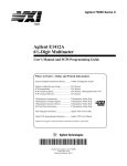
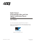
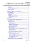
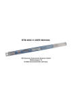
Contents
HP E1586A Rack Mount Terminal Panel User’s Manual
Description ................................................................................................................... 5
Connecting to VXIbus Instruments ............................................................................. 5
Interconnect Cables ............................................................................................... 5
Terminal Block Connections ....................................................................................... 6
Using the Terminal Panel for Reference Temperature Measurements ........................ 7
Mounting the HP E1586 Terminal Panel .............................................................. 7
Reference Thermistor Connections and Operations .............................................. 7
Using the Option 001 RF Filter ................................................................................... 9
Analog Inputs Using Three-wire Cabling ............................................................. 9
Analog Inputs Using Two-Wire Cabling ............................................................ 10
Configuration for HP E1413/E1415 with Digital I/O SCPs ............................... 11
Typical Reference Temperature Measurements ........................................................ 12
Measuring Using the Center Thermistor ............................................................. 13
Measuring Using the Left, Center, and Right Thermistors ................................. 14
Contents
1
2
Contents
Certification
Hewlett-Packard Company certifies that this product met its published specifications at the time of shipment from the factory. HewlettPackard further certifies that its calibration measurements are traceable to the United States National Institute of Standards and
Technology (formerly National Bureau of Standards), to the extent allowed by that organization's calibration facility, and to the
calibration facilities of other International Standards Organization members.
Warranty
This Hewlett-Packard product is warranted against defects in materials and workmanship for a period of three years from date of shipment.
Duration and conditions of warranty for this product may be superseded when the product is integrated into (becomes a part of) other HP
products. During the warranty period, Hewlett-Packard Company will, at its option, either repair or replace products which prove to be
defective.
For warranty service or repair, this product must be returned to a service facility designated by Hewlett-Packard (HP). Buyer shall prepay
shipping charges to HP and HP shall pay shipping charges to return the product to Buyer. However, Buyer shall pay all shipping charges,
duties, and taxes for products returned to HP from another country
HP warrants that its software and firmware designated by HP for use with a product will execute its programming instructions when
properly installed on that product. HP does not warrant that the operation of the product, or software, or firmware will be uninterrupted
or error free.
Limitation Of Warranty
The foregoing warranty shall not apply to defects resulting from improper or inadequate maintenance by Buyer, Buyer-supplied pr oducts
or interfacing, unauthorized modification or misuse, operation outside of the environmental specifications for the product, or improper
site preparation or maintenance.
The design and implementation of any circuit on this product is the sole responsibility of the Buyer. HP does not warrant the Buyer's
circuitry or malfunctions of HP products that result from the Buyer's circuitry. In addition, HP does not warrant any damage that occurs
as a result of the Buyer's circuit or any defects that result from Buyer-supplied products.
NO OTHER WARRANTY IS EXPRESSED OR IMPLIED. HP SPECIFICALLY DISCLAIMS THE IMPLIED WARRANTIES OF
MERCHANTABILITY AND FITNESS FOR A PARTICULAR PURPOSE.
Exclusive Remedies
THE REMEDIES PROVIDED HEREIN ARE BUYER'S SOLE AND EXCLUSIVE REMEDIES. HP SHALL NOT BE LIABLE FOR
ANY DIRECT, INDIRECT, SPECIAL, INCIDENTAL, OR CONSEQUENTIAL DAMAGES, WHETHER BASED ON CONTRACT,
TORT, OR ANY OTHER LEGAL THEORY.
Notice
The information contained in this document is subject to change without notice. HEWLETT-PACKARD (HP) MAKES NO
WARRANTY OF ANY KIND WITH REGARD TO THIS MATERIAL, INCLUDING, BUT NOT LIMITED TO, THE IMPLIED
WARRANTIES OF MERCHANTABILITY AND FITNESS FOR A PARTICULAR PURPOSE. HP shall not be liable for errors
contained herein or for incidental or consequential damages in connection with the furnishing, performance or use of this material. This
document contains proprietary information which is protected by copyright. All rights are reserved. No part of this document may be
photocopied, reproduced, or translated to another language without the prior written consent of Hewlett-Packard Company. HP assumes
no responsibility for the use or reliability of its software on equipment that is not furnished by HP.
HP E1586A Rack Mount Terminal Panel Installation and User's Manual
Edition 1
Copyright © 1996 Hewlett-Packard Company. All Rights Reserved.
Front Matter
3
Documentation History
All Editions and Updates of this manual and their creation date are listed below. The first Edition of the manual is Edition 1. The Edition
number increments by 1 whenever the manual is revised. Updates, which are issued between Editions, contain replacement pages to
correct or add additional information to the current Edition of the manual. Whenever a new Edition is created, it will contain all of the
Update information for the previous Edition. Each new Edition or Update also includes a revised copy of this documentation hist ory page.
Edition 1 . . . . . . . . . . . . . . . . . . . . . . . . . . . . . . . . . . . . . . . . . . . . . . . Mayl 1996
Safety Symbols
Instruction manual symbol affixed to
product. Indicates that the user must refer to
the manual for specific WARNING or
CAUTION information to avoid personal
injury or damage to the product.
Alternating current (AC)
Direct current (DC).
Indicates hazardous voltages.
Indicates the field wiring terminal that must
be connected to earth ground before
operating the equipmentÅprotects against
electrical shock in case of fault.
or
Frame or chassis ground terminal—typically
connects to the equipment's metal frame.
Calls attention to a procedure, practice, or
WARNING condition that could cause bodily injury or
death.
Calls attention to a procedure, practice, or
CAUTION condition that could possibly cause damage to
equipment or permanent loss of data.
WARNINGS
The following general safety precautions must be observed during all phases of operation, service, and repair of this product. Failure to
comply with these precautions or with specific warnings elsewhere in this manual violates safety standards of design, manufacture, and
intended use of the product. Hewlett-Packard Company assumes no liability for the customer's failure to comply with these requirements.
Ground the equipment: For Safety Class 1 equipment (equipment having a protective earth terminal), an uninterruptible safety earth
ground must be provided from the mains power source to the product input wiring terminals or supplied power cable.
DO NOT operate the product in an explosive atmosphere or in the presence of flammable gases or fumes.
For continued protection against fire, replace the line fuse(s) only with fuse(s) of the same voltage and current rating and type. DO NOT
use repaired fuses or short-circuited fuse holders.
Keep away from live circuits: Operating personnel must not remove equipment covers or shields. Procedures involving the removal of
covers or shields are for use by service-trained personnel only. Under certain conditions, dangerous voltages may exist even with the
equipment switched off. To avoid dangerous electrical shock, DO NOT perform procedures involving cover or shield removal unless you
are qualified to do so.
DO NOT operate damaged equipment: Whenever it is possible that the safety protection features built into this product have been
impaired, either through physical damage, excessive moisture, or any other reason, REMOVE POWER and do not use the product until
safe operation can be verified by service-trained personnel. If necessary, return the product to a Hewlett-Packard Sales and Service Office
for service and repair to ensure that safety features are maintained.
DO NOT service or adjust alone: Do not attempt internal service or adjustment unless another person, capable of rendering first aid and
resuscitation, is present.
DO NOT substitute parts or modify equipment: Because of the danger of introducing additional hazards, do not install substitute parts
or perform any unauthorized modification to the product. Return the product to a Hewlett-Packard Sales and Service Office for service
and repair to ensure that safety features are maintained.
4
Front Matter
HP E1586A Rack Mount Terminal Panel
Description
The HP E1586 Rack Mount Terminal Panel provides extended connections
to certain VXIbus instruments, like the HP E1413C High Speed A/D
Converter, HP E1415A Algorithmic Closed Loop Controller, and HP
E1476A 64-Channel T/C and Low Offset Relay Multiplexer. The Terminal
Panel is recommended if the VXIbus instruments are located a distance
away from the measurement connections. The Terminal Panel provides up
to 32 3-wire connections to allow for 32 channel connections to the VXIbus
instruments.
Since the Terminal panel only provides 32 channels, use an additional HP
E1586 Terminal Panel when using it with an HP E1413C, E1415A, or
E1476A.
The Terminal Panel also provides three on-board thermistors for sensing the
isothermal reference temperature of the Terminal Panel. The three
thermistors provide substantial accuracy improvements when temperature
gradients are generated across the length of the Terminal Panel.
The HP E1586 Terminal Panel can be ordered with optional High Frequency
Common Mode Filters (i.e., HP E1586 Option 001, RF Filters). These filters
are connected to the input terminal and are used to filter out AC common
mode signals present in the cables that connect between the terminal panel
and the device under test. The filters are useful for filtering out small
common mode signals below 5 Vp-p. To order these filters, order HP E1586
Option 001.
Connecting to VXIbus Instruments
Figure 1 on page 6 shows how to connect the Terminal Panel to a VXIbus
instrument. The connections are made to an HP E1413C Option A3F
Terminal Module.
Interconnect Cables
The panel uses SCSI cables to make the connections to the VXIbus modules.
Note that the modules must have the correct Terminal Modules (e.g., HP
E1413C/E1415A Opt A3F) installed to make these connections. Each cable
provides connections for 16-channels thus each Terminal Panel requires two
cables to make 32-channel connections.
The cables do not come with the Terminal Panel and must be ordered
separately. The available cables described in the following.
Standard Cable
This cable (HP E1588A) is a 16-channel twisted pair cable with an outer
shield. This cable is suitable for relatively short cable runs.
HP E1586A Rack Mount Terminal Panel
5
C-Size VXIbus Module
SCSI Cables
Option A3F
Terminal Module
*Optional
Option 001 Board
Option A3F
Terminal Module
HP E1586A
Terminal Panel
SCSI Cables
HP E1586A
Terminal Panel
*Optional
Option 001 Board
* To use the HP E1586 Terminal Panel WITHOUT
the Option 001 Board, Plug the SCSI Cables
directly into the E1586 Terminal Panel
Figure 1. Connecting the Terminal Panel
Custom Length Cable
This cable (HP Z2220A Option 050) is available in custom lengths. It is a
16-channel twisted pair cable with each twisted pair individually shielded to
provide better quality shielding for longer cable runs.
Terminal Block Connections
Figure 2 on page 7 shows typical connections to the Terminal Panel. The
panel provides four terminal blocks for the connections. These blocks
consist of eight three-wire sets of terminals with each terminal set marked
HI, LO, and G. The HI marking is for High connection, LO is for Low
connections, and G is for Guard connections.
Each terminal set also includes channel numbers, like 0(32), 4(36), etc.,
where the numbers outside the parenthesis indicate channels 00-31, and the
numbers inside the parenthesis indicate channels 32-63. These numbers, and
the HI, LO, and G terminals, correspond directly to the channel numbers and
input terminals of the HP E1413C and E1415A.
6 HP E1586A Rack Mount Terminal Panel
Using the Terminal Panel for Reference Temperature
Measurements
The following explains how to use the Terminal Panel as an isothermal
reference panel for thermocouple measurements. This explanation is for
connections to an HP E1413C High Speed A/D Converter or an HP E1415A
Algorithmic Closed Loop Controller
Mounting the HP
E1586 Terminal
Panel
The Terminal Panel can be mounted in a standard size instrument rack. To
minimize temperature gradients across the panel, it should be mounted in the
rack such that it is away from the other heat sources. The bottom of the rack
is usually the preferred location. Take particular care to minimize the
temperature differences across the horizontal width of the Terminal Panel,
since it is most susceptible to horizontal temperature gradients across its
longest dimension.
Reference
Thermistor
Connections and
Operations
The HP E1586 Terminal Panel’s three thermistors are located next to the
channel 3 terminal block, between channels 11 and 16, and next to channel
24 (see Figure 2 on page 7).
Thermistor Excitation
Sources
Both an HP E1413C or E1415A provides a 122uA current source as the
excitation for the thermistors. This is available on the Terminal Panel’s
terminals labeled HI-I and LO-I. For other modules, use an external
Voltmeter or Multimeter like the HP E1411 or E1412.
The excitation current is ONLY available to the Terminal panel connected
to channels 00-31 of the HP E1413C/E1415A. This current is NOT on the
Terminal Panel connected to channels 32-63 of the HP E1413C/E1415A.
Channels
0-3 or 32-35
Terminal Block
Channels
4-7 or 36-39
Terminal Block
Channels
8-11 or 40-43
Terminal Block
Thermistor
Terminal
Block
Channels
12-15 or 44-47
Terminal Block
Channels
16-19 or 48-51
Terminal Block
Channels
20-23 or 52-55
Terminal Block
Channels
24-27 or 56-59
Terminal Block
Thermistor
Terminal
Block
Channels
28-31 or 60-63
Terminal Block
Figure 2. Terminal Panel Connections
HP E1586A Rack Mount Terminal Panel
7
The following shows how to connect the thermistors to the HP E1413C/
E1415A current source. For the Terminal Panel’s on-board thermistors
excitation, connect HI-I to HI-TI, and LO-I to LO-TI, respectively.
Connecting One Terminal Panel for Reference Temperature
Measurements
In this configuration, a single Terminal Panel is used with an HP E1413C/
E1415A to provide up to 32 channels for temperature measurements. Make
the following connections on the thermistor terminal block of the Terminal
Panel: Connect HI-I to HI-TI Connect LO-I to LO-TI
This provides the excitation current to all three on-board thermistors on the
Terminal Panel. Figure 3 on page 8 shows the connection for a single
Terminal Panel
Connects All
Thermistors
One HP E1586 Terminal Panel
using All Thermistors
Figure 3. Connecting Three Thermistors on a Single Panel
Connecting Two Terminal Panels for Reference Temperature
Measurements
In this configuration, two Terminal Panels are used with an HP E1413C/
E1415A to provide up to 64 channels for temperature measurements. Make
the following connections on the thermistor terminal blocks of both
Terminal Panels:
Connect HI-I to HI-TI of the First Terminal panel Connect LO-I to LO-TI of
the First Terminal Panel Connect LO-TI of the First Terminal Panel to HITI of the Second Terminal Panel Connect LO-TI of the Second Terminal
Panel to LO-I of the First Terminal Panel.
This provides the excitation current to all six on-board thermistors on the
Terminal Panels. Figure 4 on page 9 shows the connection for two Terminal
Panels.
8 HP E1586A Rack Mount Terminal Panel
Connect
All Thermistors
on Both Panels
Two HP E1586 Terminal Panels
using All Thermistors on Each Panel
Figure 4. Connecting Six Thermistors on Two Panels
Using the Option 001 RF Filter
The HP E1586 Option 001 Terminal Panel has an additional board that
contains the RF Filters. These filters consist of a 3-winding common-mode
transformers for each channel. These transformers greatly attenuate
common mode signals above 1 kHz. In combination with a properly
connected Option 001 Terminal Panel, the HP E1413C/E1415A can achieve
common mode rejection ratios of >100 dB for signals from DC to >10 Mhz.
These transformers do not limit the measurement bandwidth of the HP
E1413C/E1415A. The RF Filter Board, using on board jumpers, can be
configured for various wiring and Signal Conditioning Plug-on (SCP)
combinations for the HP E1413/E1415.
Analog Inputs
Using Three-wire
Cabling
In this configuration, the HI, LO, and shield terminals are used for each
channel. This is the preferred wiring for configuration of low level analog
channels and provides the best common-mode rejection performance. To
configure the Terminal Panel, move the jumpers for each channel as shown
in Figure 5 on page 10.
The configuration in the figure removes the RC-filters from the path and
enables the common-mode transformers. Be sure the side by jumpers are
moved into the same position, or poor Common Mode Rejection will result.
HP E1586A Rack Mount Terminal Panel
9
RC Filters Removed from Signal Path and
Common-mode Transformer Enabled
Figure 5. Option 001 Three-Wire Cable Configuration
Analog Inputs
Using Two-Wire
Cabling
In this configuration, the HI and LO terminals are used for each channel,
without the shield terminal being used. This is not the preferred wiring for
low noise rejection, but may be necessary for certain configurations. For
example, some isolation Signal Conditioning Plug-ons used by the E1413 or
E1415, such as the E1514, E1515, E1516, and E1517, must use this
configuration. This is because those SCPs have no shield connections
available. To configure the Terminal Panel, move the jumpers for each
channel as shown in Figure 6 on page 11.
Since there is no shield available to drive the third winding of the
common-mode transformer, the transformer effectiveness is reduced. To
provide additional high frequency filtering, RC filters are provided on the
board.
Use of the filters decreases the low-frequency Common-mode Rejection to
about 90 dB at 60 Hz, and the measurement bandwidth to about 10 kHz for
the E1413 or E1415.
10
HP E1586A Rack Mount Terminal Panel
RC Filters Placed Into the Signal Path and
Common-mode Transformer Enabled
Figure 6. Option 001 Two-Wire Cable Configuration
Configuration for
HP E1413/E1415
with Digital I/O
SCPs
This configuration should be used for the HP E1413/E1415 Digital I/O
Signal Conditioning Plug-on (SCP). This especially the case when low level
analog SCPs are used with the digital I/O SCP. This configuration may make
it necessary to connect the digital channels through the E1586 Option 001
board. To configure the Terminal Panel, when using a digital I/O SCP, move
the jumpers for each affected channel as shown in Figure 7 on page 12
HP E1586A Rack Mount Terminal Panel
11
RC Filters Removedfrom the Signal Path and
Common-mode Transformer Disabled
Figure 7. Option 001 Digital I/O SCP Configuration
Typical Reference Temperature Measurements
The following shows how to make reference temperature measurements on
the E1586 thermistors using the HP E1413 High Speed A/D Converter or the
HP E1415A Algorithmic Closed Loop Controller.
The methods to measure the thermistor reference temperature depends on
the location of the Terminal Panel. For Terminal Panels mounted away from
heat sources, it is only necessary to measure the center thermistor. Use the
information in “Measuring Using the Center Thermistor“.
For Terminal Panels mounted in such a way that temperature gradients are
generated along its length, measure all three thermistors. Use the
information in “Measuring Using the Left, Center, and Right Thermistors”.
12
HP E1586A Rack Mount Terminal Panel
Measuring Using
the Center
Thermistor
To measure the center thermistor, select an HP E1413C or E1415A channel
as a reference channel. Connect the reference channel’s HI and LO to the
center thermistor (thermistor 2) HI-T2S and LO-T2S terminals,
respectively. These connections are shown in Figure 8 on page 13.
If two Terminal Panels are used, each panel must be connected as above so
that both panels provide reference temperature measurements. These
connections are shown in Figure 9 on page 14.
Use the information in the HP E1414C/E1415A User’s manuals to setup the
instruments to make the reference measurements. The following is an
example that uses two Terminal Panels to measure type K thermocouples.
SENS:REF THER,5000,1,(@100,132)
measures reference temperature measurements on channels 100 and 132
SENS:FUNC:TEMP TC,K,.06,(@101:131,133:163)
defines channels for temperature measurements
ROUT:SEQ:DEF (@100,101:131,132,133:163)
defines the scan list.
One HP E1586 Terminal Panel
Measuring One Thermistor
on Reference Channel 100
Figure 8. Center Thermistor Measurements on a Single Panel
HP E1586A Rack Mount Terminal Panel
13
Two HP E1586 Terminal Panels
Measuring One Thermistor on Each Panel
on Reference Channels 100, 132
Figure 9. Center Thermistor Measurements on Multiple Panels
Measuring Using
the Left, Center, and
Right Thermistors
To measure all three thermistors, select three HP E1413C/E1415A channels
as reference channels. The recommended method is to use thermistor 1, the
left thermistor (HI-T1S and LO-T1S), as a reference for channels 0 - 7 (or
32 - 39), thermistor 2, the center thermistor (HI-T2S and LO-T2S), for
channels 8 - 23 (or 40 - 47), and thermistor 3, the right thermistor (HI-T3S
and LO-T3S), for channels 24 - 31 (or 56 - 63). Connect the reference
channels HI and LO terminals to the respective
Connect the reference channel’s HI and LO terminals to the appropriate
thermistor terminals (e.g., channel 100 HI and LO terminals to thermistor 1
HI-T1S and LO-T1S terminals, respectively). These connections are shown
in Figure 10 on page 15.
If two Terminal Panels are used, each panel must be connected as above so
that both panels provide reference temperature measurements. These
connections are shown in Figure 11 on page 16.
Use the information in the HP E1414C/E1415A User’s manuals to setup the
instruments to make the reference measurements. The following are two
examples that measure type K thermocouples. One example uses a single
Terminal Panel and the other uses two Terminal Panels.
14
HP E1586A Rack Mount Terminal Panel
One HP E1586 Terminal Panel
Measuring Three Thermistors
on Reference Channels 100, 101, 102
Figure 10. Left, Center, and Right Thermistor Measurements on a Single Panel
Example Using a Single
Terminal Panel:
SENS:REF THER,5000,1,(@100,101,102)
measures reference temperature measurements on channels 100 to 102
SENS:FUNC:TEMP TC,K,.06,(@103:131)
defines channels for temperature measurements
ROUT:SEQ:DEF (@100,103:107,101,108:123,102,124:131)
defines the scan list
Example Using Two
Terminal Panels:
SENS:REF THER,5000,1,(@100,101,102,132,133,134)
measures reference temperature measurements on channels 100 to 102
SENS:FUNC:TEMP TC,K,.06,(@103:131,135:163)
defines channels for temperature measurements
ROUT:SEQ:DEF (@100,103:107,101,108:123,102,
124:131,132,135:139,133,140:155,134,156:163)
defines the scan list
Note that each reference channel (100, 101, 102, 132, 133, 134) immediately
precedes its associated measurement channels in the scan list.
HP E1586A Rack Mount Terminal Panel
15
Two HP E1586 Terminal Panels
Measuring One Thermistor on Each Panel
on Reference Channels 100, 101, 102
132, 133, 134
Figure 11. Left, Center, and Right Thermistor Measurements on Multiple Panels
16
HP E1586A Rack Mount Terminal Panel