1
HIRSCHMANN
www.hirschmann.com
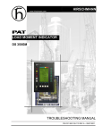
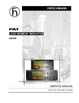
LOAD MOMENT INDICATOR
DS 350GM
for Grove Cranes
SERVICE MANUAL
TROUBLESHOOTING
P/N 031-300-190-041 REV K 12/05/2005
38 Years Specializing
in Crane Electronic Repair & Parts Sales
Call Us. We are glad to help
Bode Technical Services Inc
Email: [email protected]
Phone No.: +1.303.433.8878
38 Years Specializing
in Crane Electronic Repair & Parts Sales
Call Us. We are glad to help
Bode Technical Services Inc
Email: [email protected]
Phone No.: +1.303.433.8878
Service Manual
DS 350 GM
NOTICE
The information in this document is subject to change without notice.
Hirschmann Electronics, Inc. makes no warranty of any kind with regard to this material,
including, but not limited to the implied warranties of merchantability and fitness for a
particular purpose.
Hirschmann shall not be liable for errors contained in this manual or for incidental or
consequential damages in connection with the furnishing, performance, or use of this manual.
This document contains proprietary information, which is protected by copyright. All rights are
reserved.
No part of this document may be photocopied, reproduced, or translated into another language
without the prior written consent of Hirschmann.
Hirschmann reserves proprietary rights to all drawings and to the data shown thereon. The
drawings and data are confidential and are not to be used or reproduced without prior written
consent from Hirschmann. The drawings are subject to technical modification without prior
notice.
MANUAL REVISIONS
REV
-
DATE
11/18/98
NAME
CSH
A
01/08/98
CSH
B
02/20/98
CSH
C
06/17/99
CSH
D
10/15/99
CSH
E
11/15/99
CSH
F
G
H
J
K
01/24/00
04/25/01
04/23/02
11/07/02
12/05/05
SB
SB
CH
CH
SB
DESCRIPTION
Preliminary troubleshooting manual created for customer
review and feedback.
Add measuring points and jumper positions to drawings. Add
Theory Section 13.
Change Table of Contents
Add LED’S to DWG 7 and LED H12 TxD to pg. 17
Correct pg. 25 E91-E94 see to section 9
Correct reference notes pg. 5,15,16
Correct troubleshooting action pg. 19
Add rest boom, no pressure hydraulic lines procedure 4.
Correct minor verbiage in Theory 1,3
Add slewing angle reading problem, Section11.
Add slew potentiometer adjustment, Procedure 6.
Move error codes to Section 2.
Update/correct flow charts and drawings.
Correct Section numbers and reference numbers
Change Theory Section
Change to double sided pages
Add Grove Part Numbers
ECN 01-139
ECN 02-141
ECN 02-267
ECN 05-216
© 2000 Hirschmann, Chambersburg, PA 17201, USA
© Hirschmann Rev. K 12/05/05 // SB
38 Years Specializing
in Crane Electronic Repair & Parts Sales
Call Us. We are glad to help
190041_K
Bode Technical Services Inc
Email: [email protected]
Phone No.: +1.303.433.8878
© Hirschmann Rev. K 12/05/05 // SB
190041_K
38 Years Specializing
in Crane Electronic Repair & Parts Sales
Call Us. We are glad to help
Bode Technical Services Inc
Email: [email protected]
Phone No.: +1.303.433.8878
5
TABLE OF CONTENTS
1
General Information ......................................................................................................... 1
2
Warnings........................................................................................................................... 2
3
Flowcharts ........................................................................................................................ 3
3.1
3.2
3.3
3.4
3.5
3.6
3.7
3.8
3.9
3.10
GENERAL FLOWCHART ........................................................................................... 3
ERROR CODE DISPLAY............................................................................................ 4
LEVER LOCKOUT ACTIVATED ............................................................................... 14
BROKEN LENGTH CABLE ....................................................................................... 15
NO DISPLAY............................................................................................................. 16
ANTI-TWO BLOCK PROBLEM ................................................................................. 18
LENGTH READING PROBLEM ................................................................................ 21
ANGLE READING PROBLEM .................................................................................. 24
LOAD READING PROBLEM..................................................................................... 26
BAD DATA TRANSFER BETWEEN CONSOLE & CENTRAL UNIT OR
INTERFERENCE PROBLEM .................................................................................... 28
3.11 SLEWING ANGLE READING PROBLEM................................................................. 30
4
Drawings......................................................................................................................... 32
4.1
DRAWING 1. ELECTRICAL WIRING FOR CENTRAL UNIT TO PRESSURE
TRANSDUCERS AND CRANE ................................................................................. 32
4.2 DRAWING 2. ELECTRICAL WIRING FOR CENTRAL UNIT TO CONSOLE............ 33
4.3 DRAWING 3. ELECTRICAL WIRING FOR CENTRAL UNIT TO CABLE
REEL/ANTI-TWO BLOCK ......................................................................................... 34
4.4 DRAWING 4. CENTRAL UNIT - PARTS LIST .......................................................... 35
4.5 DRAWING 5A. CONSOLE DS350/1319 - PARTS LIST............................................ 37
4.6 DRAWING 5B. CONSOLE DS350/1318 - PARTS LIST............................................ 39
4.7 DRAWING 6. CABLE REEL - PARTS LIST .............................................................. 41
4.8 DRAWING 7. CENTRAL UNIT MAIN BOARD LAYOUT ........................................... 43
4.9 DRAWING 8. CONSOLE CONNECTION BOARD.................................................... 44
4.10 DRAWING 9. CENTRAL UNIT ANALOG INPUT MODULE ...................................... 45
5
Procedures .....................................................................................................................46
5.1 PROCEDURE 1. STRAIN RELIEF INSTALLATION ................................................. 46
5.2 PROCEDURE 2. EPROM LOCATION AND INSTALLATION ................................... 47
5.3 PROCEDURE 3. MAIN BOARD REPLACEMENT .................................................... 48
5.4 PROCEDURE 4. PRESSURE TRANSDUCER ZERO ADJUSTMENT ..................... 49
5.4.1 USING GRAPHIC CONSOLE FOR ZERO-SETTING OF PRESSURE
TRANSDUCER & FORCE INPUTS .................................................................49
5.5 PROCEDURE 5. LENGTH AND ANGLE SENSOR ADJUSTMENT ......................... 50
5.6 PROCEDURE 6. SLEW POT POTENTIOMETER ZERO ADJUSTMENT ................ 51
5.6.1 USING GRAPHIC CONSOLE FOR ZERO-SETTING OF SLEW POT
POTENTIOMETER ..........................................................................................51
© Hirschmann Rev. K 12/05/05 // SB
38 Years Specializing
in Crane Electronic Repair & Parts Sales
Call Us. We are glad to help
190041_K
Bode Technical Services Inc
Email: [email protected]
Phone No.: +1.303.433.8878
Service Manual
6
DS 350 GM
Theory .............................................................................................................................52
6.1 THEORY 1. OPERATION OF BOOM LENGTH SENSOR ........................................52
Measuring current: ...............................................................................................................52
Measuring voltage: ..............................................................................................................52
6.2 THEORY 2. OPERATION OF PISTON SIDE LOAD SENSOR .................................53
6.3 THEORY 3. OPERATION OF ROD SIDE LOAD SENSOR.......................................54
6.4 THEORY 4. OPERATION OF ANGLE SENSOR ......................................................55
6.5 THEORY 5. OPERATION OF SLEW POTENTIOMETER SENSOR.........................56
6.6 THEORY 6. OPERATION AXLE OSCILLATION OUTPUT .......................................57
© Hirschmann Rev. K 12/05/05 // SB
190041_K
38 Years Specializing
in Crane Electronic Repair & Parts Sales
Call Us. We are glad to help
Bode Technical Services Inc
Email: [email protected]
Phone No.: +1.303.433.8878
General Information
1
1
GENERAL INFORMATION
This troubleshooting manual is designed to assist a service or maintenance person in identifying
system problem areas or malfunctions. A digital voltmeter with the capability to also measure current
will be required. Regular maintenance and service tools will also be required. NOTE: Knowledge of
how to use a voltmeter to measure both voltage and current is assumed.
REFERENCE:
For system operation, refer to the operator’s manual for the console. This may differ from crane
manufacturer and model.
Section 3.1 is a general flow chart that directs you to detailed flow charts and sections.
Section 3.2 provides a list of error codes, error, cause, and possible action for the error.
Sections 3.3 – 3.11 provide detailed flow charts to define and correct the root cause.
Section 4 provides drawings that will be referenced for troubleshooting.
Section 5 provides procedures that will be referenced for troubleshooting.
Section 6 provides drawings for the theory of operation of all the different sensing devices used in the
DS350G Modular System. Use these reference drawings to better understand the operation of the
system.
© Hirschmann Rev. K 12/05/05 // SB
38 Years Specializing
in Crane Electronic Repair & Parts Sales
Call Us. We are glad to help
190041_K
Bode Technical Services Inc
Email: [email protected]
Phone No.: +1.303.433.8878
2
2
Service Manual
DS 350 GM
WARNINGS
The LMI is an operational aid that warns a crane operator of approaching overload conditions and
overhoist conditions that could cause damage to equipment and personnel. Therefore, the device is
not, and shall not be, a substitute for good operator judgment, experience and use of accepted safe
crane operating procedures.
The responsibility for the safe crane operation shall remain with the crane operator who shall ensure
that all warnings and instructions supplied are fully understood and observed.
Prior to operating the crane, the operator must carefully and thoroughly read and understand the
information in the crane’s operating manuals to ensure that the operator knows the operation and
limitations of indicator and crane.
PAT Load Moment Indicator (LMI) DS 350 Modular
The PAT Load Moment Indicator (LMI) DS 350 Modular has been designed to provide the crane
operator with the essential information required to operate the machine within the designed
parameters. Using different sensing devices, the DS 350 Modular LMI monitors various crane
functions and provides the operator with a continuous display of the crane’s capacity. The display
continually changes as the crane moves through the motions needed to make a lift.
If non-permitted conditions are approached, the DS 350 LMI will warn the operator by sounding an
audible alarm and lighting a warning light. In addition the LMI system has the capability to provide a
signal to the solenoids and thereby locking out those functions that may aggravate the crane’s
condition.
© Hirschmann Rev. K 12/05/05 // SB
190041_K
38 Years Specializing
in Crane Electronic Repair & Parts Sales
Call Us. We are glad to help
Bode Technical Services Inc
Email: [email protected]
Phone No.: +1.303.433.8878
Flowcharts
3
3
FLOWCHARTS
3.1
GENERAL FLOWCHART
This section explains how to handle a problem that may arise with the PAT DS 350 Modular LMI. The
procedures are given in flowchart format for the following sections. Start with the general flowchart below
that will guide you to one of the detailed flowcharts shown in Sections 2 through 11. The drawings and
procedures that are referenced in these sections can be found in Sections 12 and 13.
What’s Wrong?
Error Code Displayed
Go to Section 3.1
Lever Lockout Activated
Go to Section 3.3
Broken Length Cable
Go to Section 3.4
No display
Go to Section 3.5
Anti-Two Block Problem
Go to Section 3.6
Length Reading Problem
Go to Section 3.7
Angle Reading Problem
Go to Section 3.8
Load Reading Problem
Go to Section 3.9
Bad Data Transfer/Interference
Between Central Unit and
Console
Go to Section 3.10
Slewing Angle Reading
Problem
Go to Section 3.11
© Hirschmann Rev. K 12/05/05 // SB
190041_K
38 Years Specializing
in Crane Electronic Repair & Parts Sales
Call Us. We are glad to help
Bode Technical Services Inc
Email: [email protected]
Phone No.: +1.303.433.8878
4
3.2
Service Manual
DS 350 GM
ERROR CODE DISPLAY
PROBLEM: Error code displayed. Lever lockout activated. Warning lights on.
ERROR
CODE
E01
ERROR
CAUSE
ACTION
Minimum radius or
maximum angle range
exceeded
Lower boom back to a radius or
angle given in the load chart.
E02
Maximum radius or
minimum angle range
exceeded
E03
Prohibited slewing range
(no load area)
Operating mode not
available or non
permitted slewing zone.
Fallen below the minimum
radius or above the angle
given in the load chart due to
raising the boom to far.
The maximum radius or
minimum angle given in the
load chart was exceeded due
to lowering the boom too far.
Slewing range prohibited with
load.
A non existing operating mode
has been selected. The boom
Is in a non permitted slewing
zone.
Boom has been extended too
far or not far enough. Length
sensor adjustment changed;
i.e. length sensor cable slid off
the cable drum.
Fallen below the minimum jib
angle specified n the
respective load chart due to
luffing out the jib too far.
Overload relay is stuck,
defective or not being
selected.
Anti-Two-Block switch relay is
defective or not being
selected.
With the boom fully retracted,
the length differs by more than
2%.
E04
E05
Length range not
permitted
E06
Fallen below angle
range with luffing jib
operation.
E07
No acknowledgment
signal from overload
relay (K1).
No acknowledgment
signal from Anti-TwoBlock switch relay (K2).
Error in length
measurement
E08
E10
© Hirschmann Rev. K 12/05/05 // SB
Raise boom back to a radius or
angle given in the load chart.
Slew back into admissible range.
Set operating mode switch correctly
to the code assigned to the
operating mode of the crane. Slew
the boom to a permitted area.
Refer to Section 3.7.
Retract or extend boom to correct
length given in the load chart.
Luff in the jib to a radius or angle
specified in the load chart.
Replace main board in central unit.
Refer to Drawing 4 and Procedure 3
in Section 5.3
Replace main board in central unit.
Refer to Drawing 4 and Procedure 3
in Section 5.3.
Refer to Section 3.7.
190041_K
38 Years Specializing
in Crane Electronic Repair & Parts Sales
Call Us. We are glad to help
Bode Technical Services Inc
Email: [email protected]
Phone No.: +1.303.433.8878
Flowcharts
5
ERROR
CODE
E11
ERROR
CAUSE
ACTION
Fallen below limit for the
measuring channel
“length”.
a.) Cable between length
sensor and central unit
defective, not connected or
water in the connectors.
b.)Length sensor
Potentiometer defective.
c.)Electronic board in the
measuring channel defective.
Refer to Section 3.7
a.)Check cable and connector
b.) Check and reset length sensor
Potentiometer. Refer to Procedure
5.
c.) Check signal on main board and
analog input module.
E12
Fallen below lower limit
value for the measuring
channel “pressure
transducer piston side”.
Refer to Section 3.9
a.)Check cable and connector
b.) Check pressure transducer and
reset pressure channel.
c.) Check signal on main board and
analog input module.
E13
Fallen below lower limit
value for the measuring
channel “pressure
transducer rod side”.
E14
Fallen below lower limit
value for the measuring
channel “force”.
E 15
Fallen below lower limit
value for the measuring
channel “angle main
boom”.
a.) Cable leading from the
central unit to the pressure
transducer defective, loose or
water in the connector.
b.)Pressure transducer on
piston side defective.
c.)Electronic component in the
measuring channel defective.
a.)Cable leading from the
central unit to the pressure
transducer defective, loose or
water in the connector.
b.)Pressure transducer on rod
side defective.
c.)Electronic component in the
measuring channel defective.
a.)Cable leading from the
central unit to the pressure
transducer defective, loose or
water in the connector.
b.)Force transducer defective.
c.)Electronic component in the
measuring channel defective.
a.)Cable from central unit to
the length/angle sensor
defective or loose.
b.)Angle sensor defective.
c.)Electronic component in the
measuring channel defective.
© Hirschmann Rev. K 12/05/05 // SB
Refer to Section 3.9
a.)Check cable and connector
b.) Check pressure transducer and
reset pressure channel.
c.) Check signal on main board and
analog input module.
a.) Check cable and connectors as
well and replace, if necessary.
b.)Check force transducer.
c.) Check signal on main board and
analog input module.
Refer to Section 3.8
a.) Check cable.
b.) Check angle sensor and reset
adjustment. Refer to Procedure 5
c.) Check signal on main board and
analog input module.
190041_K
38 Years Specializing
in Crane Electronic Repair & Parts Sales
Call Us. We are glad to help
Bode Technical Services Inc
Email: [email protected]
Phone No.: +1.303.433.8878
6
Service Manual
DS 350 GM
ERROR
CODE
E16
ERROR
CAUSE
ACTION
Fallen below lower limit
value for measuring
channel “Luffing Jib
Angle”.
a.) Check cable.
b.) Check angle sensor and reset
adjustment.
c.) Check signal on main board and
analog input module.
E17
Fallen below lower limit
value "length telescope I
(+II)"
a.)Cable from central unit to
angle sensor defective or
disconnected or water inside
the plug.
b.)Angle sensor defective.
c.)Electronic component in the
measuring channel defective.
a.) Cable between the central
unit to the length sensor
defective or loose. Water
inside the length sensor plug.
b.) Length potentiometer
defective
c.) Electronic component in
the measuring channel
defective
Front outrigger overloaded
Electronic component on the
main board defective.
a.)Cable from central unit to
the slewing angle sensor
defective or loose.
b.)Slewing angle
potentiometer defective.
c.)Electronic component in the
measuring channel defective
on main board.
a.)Cable from central unit to
the length/angle sensor
defective or loose.
b.)Length potentiometer
defective.
c.)Electronic component in the
measuring channel defective
on main board.
E18
E19
E1A
outrigger overloaded
Error in the reference
voltage.
Below limiting value for
slewing angle 1.
E1B
Below limiting value for
slewing angle 2.
E21
Upper limiting value for
the measuring channel
“length” exceeded.
© Hirschmann Rev. K 12/05/05 // SB
a.) Check cable and connectors.
b.) Replace length sensor.
c.) Replace LMI main board or
processor board.
Check outrigger sensor
Replace main board. Refer to
Drawing 4 and Procedure 3.
Refer to Section 3.11.
a.) Check cable.
b.) Check and reset slewing angle
potentiometer. Refer to Procedure
6.
c.) Check signal on main board and
analog input module.
Refer to Section 3.7
a.) Check cable and connector
b.) Check and reset length sensor
Potentiometer. Refer to Procedure
5.
c.) Check signal on main board and
analog input module.
190041_K
38 Years Specializing
in Crane Electronic Repair & Parts Sales
Call Us. We are glad to help
Bode Technical Services Inc
Email: [email protected]
Phone No.: +1.303.433.8878
Flowcharts
ERROR
CODE
E22
7
ERROR
CAUSE
ACTION
Upper limiting value for
the measuring channel
“pressure piston side”
exceeded.
a.)Cable from central unit to
the pressure transducer
defective, loose or water in
the plug.
b.)Pressure transducer on
piston side defective.
c.)Electronic component in the
measuring channel defective
on main board.
a.) Cable lead in from the
central unit to press trans
defective, not connected or
water in the connectors.
b.) Pressure transducer on
rod side defective.
c.) Electronic component in
the measuring channel
defective.
a.) Cable leading from the
central unit to the force
transducer defective, not
connected or water in the
connectors.
b.) Force transducer
defective.
c.) Electric component in the
measuring channel defective.
a.) Cable leading from the
central unit to the length/angle
sensor defective, loose or
water in the connectors.
b.) Angle sensor defective
c.) Electronic component in
the measuring channel
defective.
a.) Cable leading from the
central unit to the jib angle
sensor defective, loose or
water in the connectors.
b.) Jib angle sensor defective.
c.) Electronic component in
the measuring channel
defective.
Refer to Section 3.9
a.) Check cable and connector
b.) Check pressure transducer and
reset pressure channel.
c.) Check signal on main board and
analog input module.
E23
Upper limit value for the
measuring channel
“pressure transducer rod
side” exceeded.
E24
Upper limit value for the
measuring channel
“force” exceeded.
E25
Upper limit value for the
measuring channel
“angle main boom”
exceeded.
E26
Upper limit value for the
measuring channel
“Luffing Jib Angle”
exceeded.
© Hirschmann Rev. K 12/05/05 // SB
Refer to Section 3.9
a.) Check cable and connector
b.) Check pressure transducer and
reset pressure channel.
c.) Check signal on main board and
analog input module.
a.) Check cable and connectors as
well and replace, if necessary. b.)
Check force transducer.
c.) Check signal on main board and
analog input module.
Refer to Section 3.8
a.) Check cable.
b.) Check angle sensor and reset
adjustment. Refer to Procedure 5
c.) Check signal on main board and
analog input module.
a.) Check cable.
b.) Check angle sensor and reset
adjustment.
c.) Check signal on main board and
analog input module.
190041_K
38 Years Specializing
in Crane Electronic Repair & Parts Sales
Call Us. We are glad to help
Bode Technical Services Inc
Email: [email protected]
Phone No.: +1.303.433.8878
8
ERROR
CODE
E27
Service Manual
DS 350 GM
ERROR
CAUSE
ACTION
Upper limit value in
measuring channel
"length telescope I (+II)
has been exceeded.
a.) Cable between the central
unit to the length sensor
defective or loose. Water
inside the length sensor plug.
b.) Length potentiometer
defective
c.) Electronic component in
the measuring channel
defective
a.) The total of the supply and
the reference voltages on
MP10 is more than 3.3V
b.) A/D converter defective.
a.) Check cable and connectors.
E29
Reference voltage
defective.
E2A
Above limiting value for
slewing angle 1.
E2B
Above limiting value for
slewing angle 2.
E31
Error in the system
program.
E37
Error in the program run
E38
System program and
Data EPROM do not
match.
E39
System program and
TLK EPROM do not
match.
E41
Error in the external
RAM.
a.)Cable from central unit to
the slewing angle sensor
defective or loose.
b.)Slewing angle
potentiometer defective.
c.)Electronic component in the
measuring channel defective
on main board.
a.) EPROM with system
program defective.
b.) Electronic component on
the main board defective.
a.) EPROM with system
program defective.
b.) Electronic component on
the main board defective.
The system program in the
LMI does not correspond to
the programming in the data
EPROM
The system program in the
LMI does not correspond to
the programming in the data
EPROM
Defective electronic
component.
© Hirschmann Rev. K 12/05/05 // SB
b.) Replace length sensor.
c.) Replace LMI main board or
processor board.
a.) Check supply voltages.
b.) Replace main board or analog
input module. Refer to Drawing 4
and Procedure 3 Steps 1,2,4,
11,12..
Refer to Section 3.11.
a.) Check cable 6.
b.) Check and reset slewing angle
potentiometer. Refer to Procedure
6.
c.) Check signal on main board and
analog input module.
a.) Replace system program
EPROM
b.) Check signal on main board and
analog input module.
a.) Replace system program
EPROM.
b.) Check signal on main board and
analog input module.
Replace system program EPROM
or Data EPROM. Refer to
Procedure 2
Replace system program EPROM
or TLK EPROM. Refer to Procedure
2
Replace main board or analog input
module. Refer to Drawing 4 and
Procedure 3, Steps 1,2,4, 11, and
12.
190041_K
38 Years Specializing
in Crane Electronic Repair & Parts Sales
Call Us. We are glad to help
Bode Technical Services Inc
Email: [email protected]
Phone No.: +1.303.433.8878
Flowcharts
ERROR
CODE
E42
9
ERROR
CAUSE
ACTION
Error in the external
write/read memory
(RAM). Part 1
Internal defect in digital part of
CPU.
E43
Error in the external
write/read memory
(RAM). Part 2.
Internal defect in digital part of
CPU.
E45
Redundancy error in
A/D conversion.
Defective electronic
component.
E46
Error in A/D
conversion.
Defective electronic
component.
E47
Malfunction in the
monitored write/read
memory.
Cyclic RAM test: Error
in the internal
write/read memory.
Error in data EPROM.
Internal defect in digital part of
CPU
Exchange write/read memory
(CMOS-RAM). Replace CPU
module. Refer to Drawing 4 and
Procedure 3, Steps 1-3, 13,14.
Exchange write/read memory
(CMOS-RAM). Replace CPU
module. Refer to Drawing 4 and
Procedure 3, Steps 1-3, 13,14.
Replace analog input module. Refer
to Drawing 4 and Procedure 3,
Steps 1,2,4, 11,12.
Replace analog input module. Refer
to Drawing 4 and Procedure 3
Steps 1,2,4, 11,12.
Replace CPU module. Refer to
Drawing 4 and Procedure 3 Steps
1-3, 13,14
Replace CPU module. Refer to
Drawing 4 and Procedure 3 Steps
1-3, 13,14
Replace Data EPROM. Make sure
BR3 on the main board is installed.
Refer to Procedure 2.
E48
E51
E52
Error in load chart
EPROM.
E56
Error in crane data
EEPROM.
Internal defect in digital part of
CPU
EPROM Module not bridged
correctly
Data EPROM on the main
board defective.
EPROM Module not bridged
correctly
Data EPROM on the main
board defective.
Memory module wrongly
bridged.
Replace EPROM Module and reset
pressure channels. Refer to
Drawing 4 and Procedure 4.
Bridge memory module acc. To
memory type
Replace crane data EEPROM
Crane data EEPROM defective Replace EPROM Module and reset
pressure channels. Refer to Drawing
4 and Procedure 4.
© Hirschmann Rev. K 12/05/05 // SB
190041_K
38 Years Specializing
in Crane Electronic Repair & Parts Sales
Call Us. We are glad to help
Bode Technical Services Inc
Email: [email protected]
Phone No.: +1.303.433.8878
10
Service Manual
ERROR ERROR
CODE
E57
Error in serial crane data
EEPROM.
CAUSE
ACTION
Serial crane data EEPROM
does not contain valid data.
Write data on the serial crane data
EEPROM (by means of test program
or on-line function), then restart the
LMI
Replace EPROM Module and reset
pressure channels. Refer to Drawing
4 and Procedure 4.
Write data on the serial analog data
EEPROM by means of the test
program, then, restart the LMI
Replace LMI main board.
Memory module defective
E58
Error in the serial analog
data EEPROM.
E60
The number of the
selected EPROM base
and the programmed
value are not identical
No valid data in the serial
analog data EEPROM.
LMI main board defective.
Load chart EPROM defective
Base number not programmed
E61
E62
E63
Error in the boom control
extension.
Error digital inputs 1 - 8 in
the boom control
extension.
Error digital inputs 9 - 16
in the boom control
extension.
DS 350 GM
Load chart EPROM wrongly
programmed
Cable between the central unit
and the boom control
extension defective.
Profibus adapter in the central
unit defective
Profibus adapter in the Boom
control extension defective
Boom control extension
defective
Module for digital inputs in the
Boom control extension
defective
Boom control extension
defective
Module for digital inputs in the
Boom control extension
defective
Boom control extension
defective
© Hirschmann Rev. K 12/05/05 // SB
Replace load chart EPROM
Program the correct base number (1
for base 1, 2 for base 2)
Check base programming in the load
chart EPROM.
Check the cable to the boom control
extension
Replace the profibus adapter
Replace the profibus adapter
Replace the boom control extension
Replace the module for the digital
inputs
Replace the boom control extension
Replace the module for the digital
inputs
Replace the boom control extension
190041_K
38 Years Specializing
in Crane Electronic Repair & Parts Sales
Call Us. We are glad to help
Bode Technical Services Inc
Email: [email protected]
Phone No.: +1.303.433.8878
Flowcharts
11
ERROR ERROR
CODE
E64
Error analog output 1 in
the boom control
extension.
E65
E66
E69
E70
E71
E72 –
E77
E80
E84
E85
E86
Error analog output 2 in
the boom control
extension.
Error analog outputs in
the boom control
extension.
Error in the load chart
EPROM
The number of the
selected EPROM base
and the programmed
value are not identical
Error in digital output
module.
CAUSE
ACTION
Module for analog output 1 in
the Boom control extension
defective
Boom control extension
defective
Module for analog output 2 in
the Boom control extension
defective
Boom control extension
defective
Module for analog outputs in
the Boom control extension
defective
Boom control extension
defective
Memory module wrongly
bridged
Load chart EPROM defective
Replace the module for the analog
output 1
Central unit unable to
correspond with digital output
module.
Incorrect
a.) Anti Two-block relay is
acknowledgment of the
stuck or defective.
1. Relay on the main
b.) Anti Two-Block relay is not
board.
being selected due to a break
on the main board.
Analogous to E71 for the Analogous to E71 for the
relays 2...7.
relays 2...7.
Error in the slewing angle The difference between the
measurement
average of the slewing angle
and one of the wipers of the
slewing potentiometer is out of
the tolerance
Wrong rigging condition. The selected rigging condition
is not contained in the data
EPROM.
Error in the radius
The computed radius is too
determination
small (negative deflection)
Faulty percentage for at
least one telescope.
Replace the boom control extension
Replace the module for the analog
output 2
Replace the boom control extension
Replace the module for the analog
outputs
Replace the boom control extension
Bridge memory module acc. to
memory type
Replace load chart EPROM
Check supply voltage.
Replace digital output module, refer
to section 14,theory 6.
Replace main board. Refer to
Drawing 4 and Procedure 3.
Analogous to E71 for the relays
2..7.
Check the slewing potentiometer
adjustment
Replace the slewing potentiometer
Select another rigging condition
Check the programming in the data
EPROM.
Check the programming in the data
EPROM.
a) Telescope has a percentage a) Read out the percentages on the
<-25 or > 106%.
console. If a telescope has to be
extended too far: retract tele and
b) Length measurement Tele
bolt.
I+II is defective.
b) Check length measurement Tele I
(see E17)
c) Measurement of overall
c) Check length measurement (see
length is defective.
E11)
© Hirschmann Rev. K 12/05/05 // SB
190041_K
38 Years Specializing
in Crane Electronic Repair & Parts Sales
Call Us. We are glad to help
Bode Technical Services Inc
Email: [email protected]
Phone No.: +1.303.433.8878
12
ERROR
CODE
E89
Service Manual
DS 350 GM
ERROR
CAUSE
ACTION
Change of the operating
code during lifting a load.
The operating mode switch in
the console was used during
lifting a load.
E91
No data transmission
from console to central
unit. (Refer to Section 9)
a.)24V supply of console
interrupted.
b.)Interruption or accidental
ground in the line from console
electronics to central unit.
c.)Transmitter/receiver module
defective.
E92
Error in the data
transmission from
console to central unit.
(Refer to also Section
3.10)
Error in the data
transmission from central
unit to console. (Refer to
also Section 3.10)
a.) Temporary interruption of
the data line from console
electronics to central unit. b.)
Transmitter/receiver module
defective.
a.) Temporary interruption of
the data line from console
electronics to central unit. b.)
Transmitter/receiver module
defective.
a.) Interruption or accidental
ground in the line from console
electronics to central unit.
Lower the load and set the
operating mode switch correctly to
the code assigned to the actual
operating mode of the crane.
a.) Check 24V at terminal X1 of
console electronics.
b.) Check the connection between
console electronics and central unit.
c.) If accidental ground occurs, the
transmitter module in the console
electronics can be damaged.
Replace the console electronics or
main board respectively.
a.) Check the connection between
console electronics and central unit.
E93
E94
No data transmission for
central unit to console.
(Refer to also Section
3.10)
b.) Transmitter/receiver module
defective.
c.) Data-EPROM defective.
d.) CPU defective.
e.) Electromagnetic
interference (when switching
contractors or valves)
© Hirschmann Rev. K 12/05/05 // SB
Refer to Section 3.10.
a.) Check the connection between
console electronics and central unit.
b.) Replace console electronics or
main board respectively.
Refer to Section 3.10.
a.) Check the connection between
console electronics and central unit.
If you find an accidental ground, the
transmitter module in the console
electronics can be damaged.
Replace the console electronics.
b.) Replace console electronics or
main board respectively. c.)Check
data EPROM.
d.) Replace CPU module. Refer to
Drawing 4 and Procedure 3 Steps
1-3, 13,14.
e.) Eliminate interference source by
inverse diodes or varistors.
190041_K
38 Years Specializing
in Crane Electronic Repair & Parts Sales
Call Us. We are glad to help
Bode Technical Services Inc
Email: [email protected]
Phone No.: +1.303.433.8878
Flowcharts
ERROR
CODE
E95
E96
E97
E98
EAB
13
ERROR
CAUSE
ACTION
Error in the crane data
EPROM
a.) Data EPROM defective
b.) Position of jumper for the
selection of the type of EPROM
is wrong
c.) Electronics component on
the main board defective.
CPU or main board of the
console defective
a.) Replace data EPROM
b.) Check the jumper position
Error in the internal
RAM of the CPU of the
console
Error in the external
RAM of the CPU of the
console
Wrong jumper position
in the console
Short circuit in the A2B
switch circuit
a.) External RAM of the
console defective
b.) Electronic component on
the main board defective.
a.) The jumper position BR
9/BR 10 in the console does
not correspond to the actual
type of central unit.
b.) Electronic component on
the main board defective.
Short circuit in the A2B switch
Short circuit in the cable to the
A2B switch
c.) Replace CPU module. Refer to
Drawing 4 and Procedure 3 Steps
1-3, 13,14
Replace CPU module. Refer to
Drawing 4 and Procedure 3 Steps
1-3, 13,14
a.) Replace console main board
b.) Replace console main board
Refer to Drawing 5.
a.) Check the jumper position
b.) Replace console main board
Refer to Drawing 5.
Refer to Section 3.6.
Replace A2B switch
Replace cable to the A2B switch
Electronic component on the
analog input module defective.
*EB0
*EB1
*EB2
EC0
EC1
Free fall switch on
Free fall solenoid on
Free fall switch and
solenoid on
Prohibited area
* Free fall monitoring
* Free fall monitoring
* Free fall monitoring
Check analog input module. Replace
if necessary, Refer to Drawing 4 and
Procedure 3 Steps 1,2,4, 11,12.
DGA 9.4=0, DGA 9.5=0
DGA 9.4=0, DGA 9.5=0
DGA 9.4=0, DGA 9.5=0
Boom is about to collide with
the engine hood, switch off
Check values in the data prom DGA
11.5.
Approaching prohibited
area
Boom is about to collide with
the engine hood, prewarning
Check values in the data prom DGA
11.5.
* Free fall monitoring (only used with data logger DL352)
Note:
If an error message is displayed which is not contained in above list, please contact the Hirschmann
service department.
© Hirschmann Rev. K 12/05/05 // SB
190041_K
38 Years Specializing
in Crane Electronic Repair & Parts Sales
Call Us. We are glad to help
Bode Technical Services Inc
Email: [email protected]
Phone No.: +1.303.433.8878
14
3.3
Service Manual
DS 350 GM
LEVER LOCKOUT ACTIVATED
PROBLEM: The lever lockout system of the crane is activated. Crane movements “hoist up”, “telescope
out”, and “boom down” are stopped. Crane is not in overload or two-block condition.
Start
Use the key switch and the LMI by-pass button on the console to
override the LMI. Refer to the Operator’s Handbook for LMI override
instructions (pages12 and 13).
Corrected
YES
NO
Does console indicate Anti-Two-block warning?
NO
YES
Fault in crane electric
or hydraulic system.
If console display are
blank. The fault is
located in power supply,
wiring or fuses .
Fault in Anti-Two
Block system.
Check lever lockout
system in crane
service manual.
Go to Section 3.5
Go to Section 3.6
© Hirschmann Rev. K 12/05/05 // SB
If the display Load Moment
Limit Light is lit. The fault is
located in LMI, cables, wiring,
fuses, or console.
Read error code displayed on
console & go to Section 3.2.
190041_K
38 Years Specializing
in Crane Electronic Repair & Parts Sales
Call Us. We are glad to help
Bode Technical Services Inc
Email: [email protected]
Phone No.: +1.303.433.8878
Flowcharts
3.4
15
BROKEN LENGTH CABLE
PROBLEM: Damaged or broken length cable.
Replace length cable using the following procedure:
Refer to Section 4 for the following drawings:
Drawing 3 - Electrical Wiring Central Unit to Cable Reel
Drawing 6 - Cable Reel - Parts List
1.
2.
3.
4.
5.
6.
7.
8.
9.
10.
11.
12.
13.
14.
Cut old cable at cable drum.
Disconnect damaged length cable from junction box at the boom nose. Refer to Drawing 3.
Open cable reel cover and disconnect wiring from terminal block. Pull 7 conductor cable out of strain
relief. Note: Mark wires to make re-connection simpler.
Remove cable reel from mounting brackets.
Remove damaged length cable, which is mounted to the slip rings in the cable reel, from slip ring
terminal. Refer to Drawings 3.
On the back side of the cable reel, open the strain relief attached to the axle in the center of the
drum. Pull existing length cable out of the cable reel.
Pull new length cable through the hole, pipe and strain relief and push it through the axle of the
reeling drum. Tighten new strain relief to ensure sealing.
Reconnect the length cable to the slip ring. Refer to Drawing 3.
Remount cable reel to the boom.
Turn reeling drum clockwise to spool the new cable neatly onto the drum.
Set pre-load on cable reel by turning the drum counter-clockwise 5 to 8 turns.
Run the new length cable through the cable guides and wrap the length cable around the boom tip
anchor pin (4 or 5 wraps) and secure with tie wraps. Leave enough length cable to connect into the
boom tip junction box.
Connect the length cable into the boom tip junction box. Refer to Drawing 3.
Reset length potentiometer in length angle transducer (screw is located in center of white gear); with
boom fully retracted, turn potentiometer carefully counter-clockwise until it stops. Recheck length and
angle display. Refer to Procedure 5 in Section 5.5.
© Hirschmann Rev. K 12/05/05 // SB
190041_K
38 Years Specializing
in Crane Electronic Repair & Parts Sales
Call Us. We are glad to help
Bode Technical Services Inc
Email: [email protected]
Phone No.: +1.303.433.8878
16
3.5
Service Manual
DS 350 GM
NO DISPLAY
PROBLEM: Blank console display with no warning light shown. All crane moments have
been stopped.
START
Check fuses in central unit.
Correct?
NO
Replace fuses.
YES
Measure voltage on the main board terminal strip between X1:1 (+12/24V) and X1:2
(ground). This is an input voltage from the crane.
Refer to Drawing 1 in Section 4.
Correct?
NO
Check crane power supply for faulty
crane electric.
YES
Measure voltage on the main board between X1:3 (+12/24V) and X1:4 (ground).
This is an output voltage to the console.
Refer to Drawing 1 in Section 4.
Correct?
NO
Replace the main board in central unit.
Refer to Drawing 4 in Section 4 and
Replacement Procedure 3 in Section 5.
YES
NEXT PAGE
© Hirschmann Rev. K 12/05/05 // SB
190041_K
38 Years Specializing
in Crane Electronic Repair & Parts Sales
Call Us. We are glad to help
Bode Technical Services Inc
Email: [email protected]
Phone No.: +1.303.433.8878
Flowcharts
17
PREVIOUS PAGE
Measure voltage in the console between X1:1 (+12/24V) and X1:2 (ground).
Refer to Drawing 2 & 8 in Section 4.
Correct?
Check connections of the cable between
console and central unit. Replace cable if
necessary. Refer to Drawing 2 in Section 4.
NO
YES
Console/Display is defective. Replace the console.
Refer to Drawing 3 in Section 4.
YES
END
© Hirschmann Rev. K 12/05/05 // SB
190041_K
38 Years Specializing
in Crane Electronic Repair & Parts Sales
Call Us. We are glad to help
Bode Technical Services Inc
Email: [email protected]
Phone No.: +1.303.433.8878
18
3.6
Service Manual
DS 350 GM
ANTI-TWO BLOCK PROBLEM
PROBLEM: Function of Anti-Two-Block System is faulty.
START
Check to see whether or not crane is in two-block condition.
Correct?
NO
Lower hook down into safe position
YES
Check Bypass plug installed
Refer to Drawing 3 in Section 4.
Correct?
Plug appropriate bypass plug into socket of
junction box.
No
YES
Turn power off or disconnect wire from connection board X1:31 in central unit. Remove the
bypass plug and measure the resistance at the boom nose box between terminals 1 and 6
with a ohmmeter. This checks the function of the Anti-Two Block switch.
Switch closed = 0Ohms (weight installed)
Switch open => 1 Megaohm (weight removed)
Pug the bypass plug into the boom nose box.
Refer to Drawing 3 in Section 4.
Correct?
No
Check wire connections in boom nose
box. Replace Anti-Two-Block switch.
Refer to Drawing 3 in Section 4.
Yes
Next Page
© Hirschmann Rev. K 12/05/05 // SB
190041_K
38 Years Specializing
in Crane Electronic Repair & Parts Sales
Call Us. We are glad to help
Bode Technical Services Inc
Email: [email protected]
Phone No.: +1.303.433.8878
Flowcharts
19
PREVIOUS PAGE
Ensure the byass plug is plugged into the boom nose box. Measure the A2B signal in the cable
reel between X1:Brown and X2:Red wires on the slip ring with an ohmmeter.
Switch closed =4700 ±500Ohms
Switch open => 1 Megaohm
Reconnected slip ring wires.
Refer to Drawing 2 & 6 Section 4.
Correct?
No
Fault in wiring between boom nose box and cable reel. Check
for damaged length cable and wiring.
Refer to Drawing 3 Section 4.
If broken length cable, Refer to Section 3.4.
Measure the A2B signal in the cable reel between terminal 7 and 8 with an ohmmeter.
Switch closed =4700 ±500Ohms
Switch open => 1 Megaohm
Reconnected slip ring wires.
Refer to Drawing 3 Section 4.
Correct?
No
Replace slip ring
Refer to Drawing 3 & 6 in Section 4.
Measure the A2B signal in the boom base box between terminals 5 and 6
with an ohmmeter.
Switch closed =4700 ±500Ohms
Switch open => 1 Megaohm
Reconnected slip ring wires.
Refer to Drawing 3 Section 4.
Correct?
No
Fault in 7 conductor cable between cable reel and
boom base box. Check connections and replace
cable if necessary.
Refer to Drawing 3 in Section 4.
NEXT PAGE
© Hirschmann Rev. K 12/05/05 // SB
190041_K
38 Years Specializing
in Crane Electronic Repair & Parts Sales
Call Us. We are glad to help
Bode Technical Services Inc
Email: [email protected]
Phone No.: +1.303.433.8878
20
Service Manual
DS 350 GM
PREVIOUS PAGE
Connect wire #5 back to the terminal X1:31 on the connection board.
Refer to Drawing 3 in Section 4.
Turn system power off. Check Anti-Two-Block signal in central unit with ohmmeter
measure between X1:31 and X1:32.
Anti-Two-Block switch closed = 4700 Ohms ±50 0Ohms
Anti-Two-Block switch open => 1 Megaohm.
Refer to Drawing 3 in Section 4.
Correct?
Faulty wiring between boom base box and central unit.
Check connections and replace cable if necessary.
NO
YES
Disconnect X1:31 and X1:32. Check main board function by installing a temporary
resistor, 4700 Ohms between X1-31 and X1-32 in central unit. With resistor connected
alarm should be inactive.
Refer to Drawing 3 in Section 4.
Correct?
NO
Defect on main board. Replace main board.
Refer to Drawing 4 in Section 4 and
Replacement Procedure 3 in Section 5.
Reconnect Wire #5 to X1:31 and Wire #6 to X1:32
Refer to Drawing 3 in Section 4.
End
© Hirschmann Rev. K 12/05/05 // SB
190041_K
38 Years Specializing
in Crane Electronic Repair & Parts Sales
Call Us. We are glad to help
Bode Technical Services Inc
Email: [email protected]
Phone No.: +1.303.433.8878
Flowcharts
3.7
21
LENGTH READING PROBLEM
PROBLEM: Length displayed incorrect. Crane is not in “out of load chart” condition.
START
Check mechanical adjustment of length potentiometer in cable reel. With boom fully retracted, reset
potentiometer by turning it slowly counter-clockwise until it reaches a soft stop.
Refer to Drawing 6 in Section 4 and Adjustment Procedure 5 in Section 5.
Correct?
Replace length potentiometer assembly, Refer to Drawing 6 in Section 4.
Remove slip ring body from shaft and remove gear wheel from potentiometer
axle. Unscrew mounting plate and remove potentiometer assembly from
mounting plate. Remove assembly wires form terminal block. Connect new
assembly to terminal block. Reinstall mounting plate, gear wheel and slip
rings. With boom fully retracted, reset potentiometer by turning it slowly
counter-clockwise until it reaches a soft stop. Refer to Drawing 3 & 6 in
Section 4 and Adjustment Procedure 5 in Section 5.
NO
YES
Check out clutch in big gear wheel of length transducer. Extend and retract boom
to ensure that clutch is not slipping on potentiometer axle.
Refer to Drawing 6 in Section 4 and Adjustment Procedure 5 in Section 5.
Correct?
NO
Replace the gear wheel, clean potentiometer axle. Reset
length potentiometer.
Refer to Drawing 6 in Section 4 and Adjustment
Procedure 5 in Section 5.
YES
Check power supply to length transducer on main board,
terminal X1:28 (ground) and X1:26 (+12/24v)
Refer to Drawing 3 in Section 4.
Correct?
NO
Main board defective. Replace main board.
Refer to Drawing 4 in Section 4 and Replacement
Procedure 3 in Section 5 .
YES
NEXT PAGE
© Hirschmann Rev. K 12/05/05 // SB
190041_K
38 Years Specializing
in Crane Electronic Repair & Parts Sales
Call Us. We are glad to help
Bode Technical Services Inc
Email: [email protected]
Phone No.: +1.303.433.8878
22
Service Manual
DS 350 GM
PREVIOUS PAGE
Measure supply to length transducer in cable reel between terminal 1 (ground) and 3 (+12/24v)
Refer to Drawing 3 in Section 4.
Correct?
Faulty wiring between central unit and length transducer. Check wiring
NO
Measure signal from length transducer in cable reel. The return signal is a current output and must
be measured in series. Set Voltmeter to measure amps. Remove Wire #2 from X1:2 in the cable reel
and connect one voltmeter lead to wire #2 and the other lead to X1:2. The measurement should be
between 4-20ma. 4ma with the boom fully retracted and the length potentiometer set fully counterclockwise to a soft stop. 20ma with the length potentiometer turned completely clockwise 10 turns to
the soft stop. Refer to Drawings 3 & 6 in Section 4.
Correct?
NO
Replace length potentiometer assembly. Remove slip ring body from shaft and
remove gear wheel from potentiometer axle. Unscrew mounting plate and
remove potentiometer assembly from mounting plate. Remove assembly wires
from terminal block. Connect new assembly to terminal block. Reinstall
mounting plate, gear wheel and slip rings. With boom fully retracted, reset
potentiometer by turning it slowly counter-clockwise until it reaches a soft stop.
Refer to Drawing 6 in Section 4 and adjustment Procedure 5 in Section 5.
YES
Measure signal from length transducer in central unit. The return signal is a current output and must
be measured in series. Set Voltmeter to measure amps. Remove Wire #2 from X1:27 in the central
unit and connect one voltmeter lead to wire #2 and the other lead to X1:27. The measurement
should be between 4-20ma. 4ma with the boom fully retracted and the length potentiometer set fully
counter-clockwise to a soft stop. 20ma with the length potentiometer turned completely clockwise 10
turns to the soft stop. Refer to Drawing 3 & 6 in Section 4.
Correct?
NO
Faulty wiring between central unit and cable reel.
Check wiring.
YES
NEXT PAGE
© Hirschmann Rev. K 12/05/05 // SB
190041_K
38 Years Specializing
in Crane Electronic Repair & Parts Sales
Call Us. We are glad to help
Bode Technical Services Inc
Email: [email protected]
Phone No.: +1.303.433.8878
Flowcharts
23
PREVIOUS PAGE
Measure length signal of amplified output on analog input module between test
point MP0 and X1:3. The measurement should be between 0.5-4.5v.
0.5v(500mv) with the boom fully retracted and the length potentiometer set fully
counter-clockwise to a soft stop OR 4.5v with the length potentiometer turned
completely clockwise 10 turns to the soft stop.
Refer to Drawing 9 in Section 4.
Correct?
NO
Analog Input board defective.
Replace analog input board.
Refer to Drawing 4 in Section 4 and Replacement
Procedure 3 steps 4,11, & 12 in Section 4.
YES
END
© Hirschmann Rev. K 12/05/05 // SB
190041_K
38 Years Specializing
in Crane Electronic Repair & Parts Sales
Call Us. We are glad to help
Bode Technical Services Inc
Email: [email protected]
Phone No.: +1.303.433.8878
24
3.8
Service Manual
DS 350 GM
ANGLE READING PROBLEM
PROBLEM: Angle displayed incorrect. Crane is not in “out of load chart” condition.
START
Check the cable reel for damages or movement of mounting bracket.
Refer to Drawing 6 in Section 4 and Adjustment Procedure 5 in Section 5.
Correct?
Repair or replace cable reel, if damaged or
adjustments can not be made.
NO
YES
Place the boom at 0°. Measure the angle sensor supply voltage in the central unit
between terminals X1:26 (+12/24v) and X1:28 (ground).
Refer to Drawing 3 in Section 4.
Correct?
NO
Main board defective. Replace main board.
Refer to Drawing 4 in Section 4 and Replacement
Procedure 3 in Section 5 .
YES
Open cable reel cover. Measure the angle sensor supply voltage in the
cable reel between terminals X1:1 (+12/24v) and X1:3 (ground).
Refer to Drawing 3 in Section 4.
Correct?
NO
Faulty wiring between central unit and cable reel.
Check wiring
Refer to Drawing 3 in Section 4.
Yes
NEXT PAGE
© Hirschmann Rev. K 12/05/05 // SB
190041_K
38 Years Specializing
in Crane Electronic Repair & Parts Sales
Call Us. We are glad to help
Bode Technical Services Inc
Email: [email protected]
Phone No.: +1.303.433.8878
Flowcharts
25
PREVIOUS PAGE
Measure signal from angle transducer in cable reel. The return signal is a current
output and must be measured in series. Set Voltmeter to measure amps. Remove
Wire #4 from X1:4 in the cable reel and connect one voltmeter lead to wire #4 and
the other lead to X1:4. The measurement should be between 4-20ma. 20ma with the
boom at 0° or 4ma with the boom a 90° .
Refer to Drawing 3 & 6 in Section 4.
Correct?
NO
Replace angle sensor.
Refer to Drawing 6 in Section 4 and Adjustment
Procedure 5 in Section 5.
YES
Measure signal from angle transducer in central unit. The return signal is a current
output and must be measured in series. Set Voltmeter to measure amps. Remove
Wire #4 from X1:4 in the central unit and connect one voltmeter lead to wire #4 and
the other lead to X1:4. The measurement should be between 4-20ma. 20ma with the
boom at 0° or 4ma with the boom at 90° .
Refer to Drawing 3 & 6 in Section 4.
Correct?
Faulty wiring between central unit and cable reel.
Check wiring
Refer to Drawing 3 in Section 4.
NO
YES
Measure angle signal analog input module between test point MP0(AGND) and X1:4
(ang sig). The measurement should be between 0.5-4.5v. 0.5v(500mv) with the
boom at 0° or 4.5v with the boom at 90° .
Refer to Drawing 9 in Section 4.
Correct?
NO
Analog Input board defective.
Replace analog input board.
Refer to Drawing 4 in Section 4 and Replacement
Procedure 3 steps 4,11, & 12 in Section 5.
END
© Hirschmann Rev. K 12/05/05 // SB
190041_K
38 Years Specializing
in Crane Electronic Repair & Parts Sales
Call Us. We are glad to help
Bode Technical Services Inc
Email: [email protected]
Phone No.: +1.303.433.8878
26
3.9
Service Manual
DS 350 GM
LOAD READING PROBLEM
PROBLEM: Load reading incorrect.
START
Check boom length reading on display.
Correct?
NO
Reset length potentiometer. With fully retracted boom, turn potentiometer axle
counter-clockwise until it stops . Refer to Section 3.7.
YES
Measure radius and check with the displayed radius.
Correct?
NO
Check if mechanical adjustment of angle transducer is correct. Angle transducer
box should be in line with boom and adjusted to actual boom angle.
Refer to Section 3.8.
YES
Check power supply to pressure transducers (piston and rod side). Check each transducer by
unpluging the transducer cable from transducer. Measure voltage at the cable connection
between A (+12/24v) and C (ground) at each connector.
Refer to Drawing 1 in Section 4.
Correct?
Check power supply in the central unit between:
X1:20 (+12/24v) and X1:22 (ground) for piston side
and X1:23 (+12/24v) and X1:25 (ground) for rod side.
Refer to Drawing 1 and 4 in Section 4.
NO
YES
Correct?
YES
Fault in pressure transducer cable.
Refer to Drawing 1 in Section 4.
NEXT PAGE
NO
Main board defective. Replace main board.
Refer to Drawing 4 in Section 4 and Replacement
Procedure 3 in Section 5.
© Hirschmann Rev. K 12/05/05 // SB
190041_K
38 Years Specializing
in Crane Electronic Repair & Parts Sales
Call Us. We are glad to help
Bode Technical Services Inc
Email: [email protected]
Phone No.: +1.303.433.8878
Flowcharts
27
PREVIOUS PAGE
Measure signal from pressure transducers in central unit. The return signal is a current output and must
be measured in series. Set Voltmeter to measure amps.
Piston Side, remove Wire #2 from X1:21 in the central unit and connect one ammeter lead to wire #2
and the other lead to X1:21. The measurement should be between 4-20ma (4ma when there is no
pressure in the hydraulic lines; 0 psi).
Rod Side, remove Wire #2 from X1:24 in the central unit and connect one voltmeter lead to wire #2
and the other lead to X1:24. The measurement should be between 4-20ma
(4ma when there is no pressure in the hydraulic lines; 0 psi).
Refer to Drawing 1 in Section 4.
Correct?
NO
Check continuity of wire 2 and pin B in pressure transducer cable by first
unplugging the transducer cable from transducer and second moving wire 2 to
the ground terminal X1:22 or X1:25. Measure voltage at the cable connection
between A (+12/24v) and B (ground) for each connector.
Re-connect the wiring a shown on Drawing 1 in Section 4.
Refer to Drawing 1 in Section 4.
No Fault in cable
Adjust zero point on pressure transducers.
Adjustment Procedure 4 in Section 5.
If transducer(s) are not adjustable.
Replace pressure transducer(s) and adjust zero point.
Refer to Procedure 4 in Section 5.
YES
Measure pressure transducer signals on the analog input module between test points:
Piston Side, MP0 (ground) and X1:1 .
Rod Side, MP0 (ground) and X1:2.
The measurements should be between 0.5-4.5v (0.5v(500mv) at 0psi to 4.5v at 4410psi).
Refer to Drawing 4 & 9 in Section 4.
Correct?
NO
Analog Input board defective.
Replace analog input board.
Refer to Drawing 4 in Section 12 and Replacement
Procedure 3 steps 4,11, & 12 in Section 5.
YES
END
© Hirschmann Rev. K 12/05/05 // SB
190041_K
38 Years Specializing
in Crane Electronic Repair & Parts Sales
Call Us. We are glad to help
Bode Technical Services Inc
Email: [email protected]
Phone No.: +1.303.433.8878
28
3.10
Service Manual
DS 350 GM
BAD DATA TRANSFER BETWEEN CONSOLE & CENTRAL UNIT OR
INTERFERENCE PROBLEM
PROBLEM: Error Code “E93/E94" No data transfer to and from console,
interference from crane electric, or console display frozen .
START
Check the H12 (TxD) LED on the main board ON/OFF.
Refer to Drawing 7 in Section 4.
ON
Make sure that the eprom's are correct and plugged into the Eprom Module on
the main board.
Refer to Procedure 2 in Section 5.
Correct?
Place EPROM in correct socket.
Refer to Procedure 2 in Section 5.
NO
YES
OFF
Measure process voltage on the Main Board in the central unit between
MP42 (+5v) and MP0 (ground). Refer to Drawing 4 & 7 in Section 4.
Correct?
Make sure external and internal power supply is
correct - Refer to Section 3.5 No Display.
NO
YES
Turn off system power.
Check the continuity of the receive(RXD) and transfer(TXD) wires.
Check continuity between:
· central unit main board X1:5 and console X1:3
· central unit main board X1:6 and console X1:4
Refer to Drawing 2 in Section 4.
Correct?
NO
Check connections and replace cable from central unit to
console, if necessary. Refer to Drawing 2 in Section 4 and
Procedure 1 in Section 5.
NEXT PAGE
© Hirschmann Rev. K 12/05/05 // SB
190041_K
38 Years Specializing
in Crane Electronic Repair & Parts Sales
Call Us. We are glad to help
Bode Technical Services Inc
Email: [email protected]
Phone No.: +1.303.433.8878
Flowcharts
29
PREVIOUS PAGE
Check if additional ground link between main
board MP1 and central unit box mounting bracket is in place.
Refer to Drawing 7 in Section 4.
Correct?
Install ground line - single cable minimum of AWG14 (2.0mm)
between terminal MP1 and central unit box mounting bracket.
Refer to Drawing 7 in Section 4.
NO
YES
Ensure that cable shields are connected correctly.
Refer to connection and wiring diagrams, Drawings 1, 2, 3 in Section 4
and Procedure 1 in Section 5.
Correct?
Make correct shield connection.
Refer to connection and wiring diagrams,
Drawings 1, 2, 3 in Section 4 and Procedure 1 in Section 5.
NO
YES
Find out which component of the crane electric is spiking out (e.g. dump valve, outrigger
relay). Install a diode or resistor across terminals of spiking component. Diode type
such as 1N4001 can be used (watch + and - connection for diode).
Refer to Crane Electrical Diagrams.
END
© Hirschmann Rev. K 12/05/05 // SB
190041_K
38 Years Specializing
in Crane Electronic Repair & Parts Sales
Call Us. We are glad to help
Bode Technical Services Inc
Email: [email protected]
Phone No.: +1.303.433.8878
30
3.11
Service Manual
DS 350 GM
SLEWING ANGLE READING PROBLEM
PROBLEM: Slew Angle displayed incorrect.
START
Check for damages inside the slip ring to the slew pot assembly.
Correct?
Repair or replace cable and/or slew pot with
amplifier board.
NO
YES
Position the super structure over the front and engage the house lock pin. Measure
the slewing sensor supply voltage in the central unit between terminals X1:33 (+12/
24v) and X1:35 (ground).
Refer to Drawing 3 in Section 4.
Correct?
NO
Main board defective. Replace main board.
Refer to Drawing 4 in Section 4 and
Replacement Procedure 3 in Section 5.
YES
Remove the slip ring cover and measure the slewing sensor supply voltage on
the amplifier board between X1:1 (+12/24v) and X1:4 (ground).
Refer to Drawing 3 in Section 4.
Correct?
NO
Faulty wiring between central unit and slew pot.
Check wiring
Refer to Drawing 3 in Section 4.
Yes
NEXT PAGE
© Hirschmann Rev. K 12/05/05 // SB
190041_K
38 Years Specializing
in Crane Electronic Repair & Parts Sales
Call Us. We are glad to help
Bode Technical Services Inc
Email: [email protected]
Phone No.: +1.303.433.8878
Flowcharts
31
PREVIOUS PAGE
Measure signals 1 and 2 from the slew pot amplifier board in the slip ring. The return
signals are current output and must be measured in series (AMPS).
Signal 1. Remove Wire #2 from X1:2 on the amplifier board and connect one voltmeter
lead to wire #2 and the other lead to X1:2.
Signal 2. Remove Wire #3 from X1:3 on the amplifier board and connect one voltmeter
lead to wire #3 and the other lead to X1:3.
The measurements should be between 4-20ma.
Refer to Drawing 3 & 6 in Section 4.
Correct?
Replace slew pot and amplifier board.
NO
YES
Measure signals 1 and 2 from the slew pot amplifier board in the central unit. The return
signala are current output and must be measured in series (AMPS).
Signal 1. Remove Wire #2 from X1:30 on the main board and connect one voltmeter
lead to wire #2 and the other lead to X1:30.
Signal 2. Remove Wire #3 from X1:34 on the main board and connect one voltmeter lead
to wire #3 and the other lead to X1:34.
The measurements should be between 4-20ma.
Refer to Drawing 3 & 6 in Section 4.
Correct?
NO
Faulty wiring between central unit and cable reel.
Check wiring
Refer to Drawing 3 in Section 4.
Measure slew angle signals 1 and 2 from the analog input module.
Signal 1. Measure between MP0 (AGND) and X1:5 analog input module board.
Signal 2. Measure between MP0 (AGND) and X1:6 analog input module board.
The measurement should be between 0.5-4.5v. 0.5v(500mv) with the boom at 0° or 4.5v
with the boom at 90° .
Refer to Drawing 9 in Section 4.
Correct?
NO
Faulty analog input module or CPU module in central unit.
END
© Hirschmann Rev. K 12/05/05 // SB
190041_K
38 Years Specializing
in Crane Electronic Repair & Parts Sales
Call Us. We are glad to help
Bode Technical Services Inc
Email: [email protected]
Phone No.: +1.303.433.8878
32
Service Manual
DS 350 GM
4
DRAWINGS
4.1
DRAWING 1. ELECTRICAL WIRING FOR CENTRAL UNIT TO PRESSURE
TRANSDUCERS AND CRANE
CENTRAL UNIT DS350GM
MAIN BOARD: PAT 024-352-300-001 / GROVE 9-333-103287
© Hirschmann Rev. K 12/05/05 // SB
190041_K
38 Years Specializing
in Crane Electronic Repair & Parts Sales
Call Us. We are glad to help
Bode Technical Services Inc
Email: [email protected]
Phone No.: +1.303.433.8878
Drawings
4.2
33
DRAWING 2. ELECTRICAL WIRING FOR CENTRAL UNIT TO CONSOLE
CENTRAL UNIT DS350GM
MAIN BOARD: PAT 024-352-300-001 / GROVE 9-333-103287
See reference notes on Drawing 1.
© Hirschmann Rev. K 12/05/05 // SB
38 Years Specializing
in Crane Electronic Repair & Parts Sales
Call Us. We are glad to help
190041_K
Bode Technical Services Inc
Email: [email protected]
Phone No.: +1.303.433.8878
34
4.3
Service Manual
DS 350 GM
DRAWING 3. ELECTRICAL WIRING FOR CENTRAL UNIT TO CABLE REEL/ANTITWO BLOCK
CENTRAL UNIT DS350GM
MAIN BOARD: PAT 024-352-300-001 / GROVE 9-333-103287
© Hirschmann Rev. K 12/05/05 // SB
190041_K
38 Years Specializing
in Crane Electronic Repair & Parts Sales
Call Us. We are glad to help
Bode Technical Services Inc
Email: [email protected]
Phone No.: +1.303.433.8878
Drawings
4.4
35
DRAWING 4. CENTRAL UNIT - PARTS LIST
Item 21 digital output board, refer to section 6.6 for location.
© Hirschmann Rev. K 12/05/05 // SB
38 Years Specializing
in Crane Electronic Repair & Parts Sales
Call Us. We are glad to help
190041_K
Bode Technical Services Inc
Email: [email protected]
Phone No.: +1.303.433.8878
36
Service Manual
DS 350 GM
DRAWING 4. CENTRAL UNIT - PARTS LIST - continued
PART NO. A) PAT 024-350-063-001 / GROVE 9-333-103280 (12V)
PART NO. B) PAT 024-350-063-002 / GROVE 9-333-103281 (24V)
NO.
PART NO. PAT / GROVE
01
02
03
04
05
06
07A
07B
08
09
10
11
12
13
14
15
16
17
18
19
20
21
024-350-050-292 / 9333103549
024-350-110-067 / 9333101591
024-352-300-001 / 9333103287
024-352-300-020 / 9333103290
024-351-300-007 / 9333103288
024-351-300-011 / 9333103289
000-304-140-112 / 9333103550
000-304-140-241 / 9333101597
024-350-100-135 / 9333101978
000-314-022-006 / 9333102542
000-313-062-002 / 7482000019
000-313-064-001 / 9333103456
000-214-340-013 / 9333101732
021-441-131-013 / 9333101440
021-441-161-213 / 9333101735
021-441-090-709 / 9333101995
024-000-100-260 / 9333103315
024-000-100-261 / 9333103551
024-350-100-661 / 9333102541
031-300-101-131 / 9333103058
024-000-100-095 / 9333103532
024-352-300-041 / 9333103291
QTY
1
1
1
1
1
1
1
1
1
2
1
1
1
2
1
3
5
1
1
1
2
1
DESCRIPTION
HOUSING W/COVER, CENTRAL UNIT
GASKET
MAIN, BOARD
ANALOG INPUT MODULE
CPU MODULE
EPROM MODULE
RELAY 12V
RELAY 24V
SCREW SET
FUSE HOLDER
FUSE 10amp 250V FAST ACTING
FUSE 4amp 250V FAST ACTING
HOLE PLUG, PG13.5
STRAIN RELIEF, PG13.5 RED/WHT
STRAIN RELIEF, PG13.5 W/ GREY/WHT
STRAIN RELIEF, PG9 W/ BLACK/WHITE
FERRITE FILTER PG13.5
FERRITE FILTER PG16
KEYSWITCH
SPARE KEY
MEMBRANE ELEMENT, BREATHER
BOARD, DIGITAL OUTPUT
© Hirschmann Rev. K 12/05/05 // SB
190041_K
38 Years Specializing
in Crane Electronic Repair & Parts Sales
Call Us. We are glad to help
Bode Technical Services Inc
Email: [email protected]
Phone No.: +1.303.433.8878
Drawings
4.5
37
DRAWING 5A. CONSOLE DS350/1319 - PARTS LIST
GRAPHIC CONSOLE (VERTICAL), PARTS LIST
PART NO. 050-350-061-319 / 9333103278
16 17
13
14
7
15
10
18
11
12
6
2
9
4
3
5
8
1
© Hirschmann Rev. K 12/05/05 // SB
38 Years Specializing
in Crane Electronic Repair & Parts Sales
Call Us. We are glad to help
190041_K
Bode Technical Services Inc
Email: [email protected]
Phone No.: +1.303.433.8878
38
Service Manual
DS 350 GM
DRAWING 5A. CONSOLE DS350/1319 - PARTS LIST - continued
GRAPHIC CONSOLE (VERTICAL), PARTS LIST
PART NO. PAT 050-350-061-319 / GROVE 9-333-103278
NO.
PART NO. PAT / GROVE
QTY
01
02
03
04
05
06
07
08
09
10
11
12
13
14
15
16
17
18
031-300-110-048 / 9333103587
050-000-100-212 / 9333103552
050-150-300-053 / 9333103302
003-051-905-235 / 9333103406
050-350-110-139 / 9333101691
002-053-806-058 / 9333102359
050-150-300-050 / 9333103299
050-000-050-625 / 9333103223
050-150-300-051 / 9333103300
000-214-210-011 / 9333101727
000-208-010-210 / 9333103169
000-214-210-013 / 9333101547
031-300-100-392 / 9333103433
000-214-340-011 / 9333102047
021-448-161-213 / 9333102746
031-300-100-173 / 9333103226
031-300-100-024 / 9333103227
050-350-300-076 / 9333103222
1
1
1
1
1
6
1
1
1
1
1
1
1
1
1
1
1
1
DESCRIPTION
CONSOLE ACCY, FRONT FACE & DIS.
HOUSING
BOARD, PUSHBUTTON SET(KEYBRDS)
SWITCH, KEY
KEY, SPARE
SCREWS, FRONT PANEL MOUNTING
BOARD
SEALING, FRONT PANEL
TERMINAL BOARD
LOCKNUT, PG11
TOOTHWASHER, M12
LOCKNUT, PG13.5
CANNON CONN., 7-SOCKET RECPT.
HOLE PLUG PG11
STRAIN RELIEF, PG13.5 GREY/WHT
GASKET
DUST CAP
BOARD, TERMINAL INTERFACE FOR
LIGHTBAR
© Hirschmann Rev. K 12/05/05 // SB
190041_K
38 Years Specializing
in Crane Electronic Repair & Parts Sales
Call Us. We are glad to help
Bode Technical Services Inc
Email: [email protected]
Phone No.: +1.303.433.8878
Drawings
4.6
39
DRAWING 5B. CONSOLE DS350/1318 - PARTS LIST
9
10
12
13 14
7
6
2
11
17
15
2
16
10
8
4
3
5
1
© Hirschmann Rev. K 12/05/05 // SB
38 Years Specializing
in Crane Electronic Repair & Parts Sales
Call Us. We are glad to help
190041_K
Bode Technical Services Inc
Email: [email protected]
Phone No.: +1.303.433.8878
40
Service Manual
DS 350 GM
DRAWING 5B. CONSOLE DS350/1318 - PARTS LIST - continued
GRAPHIC CONSOLE (HORIZONTAL), PARTS LIST
PART NO. PAT 050-350-061-318 / GROVE 9-333-103279
NO.
PART NO. PAT / GROVE
QTY
01
02
03
04
05
06
07
08
09
10
11
12
13
14
15
16
17
031-300-110-049 / 9333103588
050-150-300-052 / 9333103301
003-051-905-235 / 9333103406
050-350-110-139 / 9333101691
002-053-703-101 / 9333102298
050-150-300-050 / 9333103299
050-150-300-051 / 9333103300
050-000-050-625 / 9333103223
050-000-100-180 / 9333103439
050-350-110-263 / 9333103225
021-448-161-213 / 9333102746
031-300-100-173 / 9333102482
031-300-100-392 / 9333103043
031-300-100-024 / 9333102612
000-208-010-210 / 9333103169
000-214-210-013 / 9333101547
050-350-300-076 / 9333103222
1
1
1
1
6
1
1
1
1
1
1
1
1
1
1
1
1
DESCRIPTION
CONSOLE ACCY, FRONT FACE & DIS.
BOARD, PUSHBUTTON SET(KEYBRDS)
SWITCH, KEY
KEY, SPARE
SCREWS, FRONT PANEL MOUNTING
BOARD
TERMINAL BOARD
SEALING, FRONT PANEL
HOUSING
MOUNTING KIT FOR HOUSING
STRAIN RELIEF, PG13.5 GREY/WHT
GASKET
CANNON CONN., 7-SOCKET RECPT.
DUST CAP
TOOTHWASHER, M12
LOCKNUT, PG13.5
BOARD, TERMINAL INTERFACE FOR
LIGHTBAR
© Hirschmann Rev. K 12/05/05 // SB
190041_K
38 Years Specializing
in Crane Electronic Repair & Parts Sales
Call Us. We are glad to help
Bode Technical Services Inc
Email: [email protected]
Phone No.: +1.303.433.8878
Drawings
4.7
41
DRAWING 6. CABLE REEL - PARTS LIST
6
2
4
5
11
1
6
3
10
7
8
9
6
© Hirschmann Rev. K 12/05/05 // SB
38 Years Specializing
in Crane Electronic Repair & Parts Sales
Call Us. We are glad to help
190041_K
Bode Technical Services Inc
Email: [email protected]
Phone No.: +1.303.433.8878
42
Service Manual
DS 350 GM
DRAWING 6. CABLE REEL - PARTS LIST - continued
CABLE REEL ASSEMBLY, PARTS LIST
PART NO. PAT 068-308-060-001 / GROVE 9333103306
NO.
PART NO. PAT / GROVE
QTY
01
02
03
04
05
06
07
08
09
10
11
068-000-300-060 / 9333103309
064-103-060-007 / 9333103303
068-000-300-018 / 9333103308
002-050-206-012 / 7121152154
000-207-010-064 / 9333101567
068-000-100-152 / 9333103376
000-214-340-013 / 9333101732
000-673-020-002 / 9333102382
002-148-131-013 / 9333102477
031-300-100-206 / 7296000504
068-000-100-064 / 9333102732
1
1
1
2
2
1
1
139’
1
1
1
DESCRIPTION
BOARD, TERMINAL W/ EMC FILTERS
ANGLE SENSOR WG103/0007
LENGTH POTENTIOMETER UNIT
SCREW M6 X 12 HEX SOCKET CAP
WASHER M6 FLAT
HOUSING KT200
PG13.5 HOLE PLUG
CABLE, LENGTH SINGLE CORE
STRAIN RELIEF, PG13.5 RED/WHT
CHEMICAL, CORROSION INHIBITOR
SLIP RING ASSEMBLY 2 POLE
© Hirschmann Rev. K 12/05/05 // SB
190041_K
38 Years Specializing
in Crane Electronic Repair & Parts Sales
Call Us. We are glad to help
Bode Technical Services Inc
Email: [email protected]
Phone No.: +1.303.433.8878
Drawings
4.8
43
DRAWING 7. CENTRAL UNIT MAIN BOARD LAYOUT
BOARD P/N
024-352-300-001
9333103287
MP24
MP1 = KGND
MP4 = +5V
MP8 = +9V
MP9 = +6V
MP24 -= +BATT
MP25 -= +UBS console,
sensors, DI’s
MP26 -= GND
MP29 -= +5V hand terminal
H11
DI1
THRU
DI6
H10
H8
7776
36 35
34 33
H9
30 29
28 27
LED’S
H08 - LOAD
H09 - A2B
H10 - MAIN IN/OUT
H11 - POWER
H12 - TxD
H12
K10
69 68
32 31
MP26
MP4
MP9
MP8
67 66
65 64
26 2
5 24
23 2
2 21
20 19
18 17
16 15
14
62 61
13 12
60 59
58 57
11 1
0 98
7
54 53
52 51
1
654
3
MP1
MP25
21
X1
© Hirschmann Rev. K 12/05/05 // SB
38 Years Specializing
in Crane Electronic Repair & Parts Sales
Call Us. We are glad to help
190041_K
Bode Technical Services Inc
Email: [email protected]
Phone No.: +1.303.433.8878
44
4.9
Service Manual
DS 350 GM
DRAWING 8. CONSOLE CONNECTION BOARD
MP5
+5V
MP2
+7V
MP3
-24V
MP4
+24V
J5
MP6
J4
MP7
4
J3
MP0
GND
1
X5
MP1
+UB
J2
J1
8
7
6
5
4
3
2
1
X1
BOARD PART NUMBER 050 150 30 0051 / 9333103300
© Hirschmann Rev. K 12/05/05 // SB
190041_K
38 Years Specializing
in Crane Electronic Repair & Parts Sales
Call Us. We are glad to help
Bode Technical Services Inc
Email: [email protected]
Phone No.: +1.303.433.8878
Drawings
4.10
45
DRAWING 9. CENTRAL UNIT ANALOG INPUT MODULE
BOARD P/N 024-352-300-020 / 9333103290
X1:1-7 = ADC INPUT 0.5V...4.5V, Note: If channel adjustments
are made through the software and graphic console, DO NOT
adjust offset with P1-P7.
X1:8 = TEMP (0.5V + 10mV/°C)
X1:9 = VREFA = 5.000V reference
X1:10 = AGND (reference GND)
X1:11 = VREF+ = 5.0V power ADC
X1:12-15
= CH01-04, DIN1-4 / 10
X1:16 = CH05, +UBS / 10
X1:17 = CH06, HESIN(A2B) * 4
X1:18 = CH07, +9V * 4
X1:19 = CH08, VREFA / 2 = 2.500V
X1:20 = UKLEMM, app. VREFA, limits ADC input to 5.0V
MP1 = AGND
MP8 = +5V
MP1-7 = Input channels 1-7 0.5V/4mA…2.5V/20mA
MP14 = +13V REF02
MP16 -= HESIN input voltage
MP17 = app 5.4V clamp for inputs
The analog input module converts the sensor signals on
channels 1-7 to signals that will be process at the CPU and
software. The incoming signal measured at the measuring
points (MP) will be 0.5V/4mA…2.5V/20mA. The analog input
module then converts the channel signals to 0.5V…4.5V, which
can be measured on X1:1 through X1:7.
The signal voltage can be measured at either point using
ground and the signal input.
© Hirschmann Rev. K 12/05/05 // SB
38 Years Specializing
in Crane Electronic Repair & Parts Sales
Call Us. We are glad to help
190041_K
Bode Technical Services Inc
Email: [email protected]
Phone No.: +1.303.433.8878
46
Service Manual
5
PROCEDURES
5.1
PROCEDURE 1. STRAIN RELIEF INSTALLATION
© Hirschmann Rev. K 12/05/05 // SB
DS 350 GM
190041_K
38 Years Specializing
in Crane Electronic Repair & Parts Sales
Call Us. We are glad to help
Bode Technical Services Inc
Email: [email protected]
Phone No.: +1.303.433.8878
Procedures
5.2
47
PROCEDURE 2. EPROM LOCATION AND INSTALLATION
SYSTEM
SY
ST
EM
DATA
DA
TA
TL
K
TLK
•
•
•
Ensure the notch is in the correct direction.
The DATA and TLK EPROMs fill the bottom of the socket as shown by the arrows.
Place EPROMs in the correct EPROM socket as shown.
© Hirschmann Rev. K 12/05/05 // SB
38 Years Specializing
in Crane Electronic Repair & Parts Sales
Call Us. We are glad to help
190041_K
Bode Technical Services Inc
Email: [email protected]
Phone No.: +1.303.433.8878
48
5.3
Service Manual
DS 350 GM
PROCEDURE 3. MAIN BOARD REPLACEMENT
Refer to Drawing 4, central unit parts list for board location.
1. Turn system power off.
2. Remove the central unit lid.
NOTE: Take care not to damage the boards with the screwdriver, when removing and inserting screws.
NOTE: Use care when lifting the CPU module board and analog input module from the main board,
due to the fact that these boards have pins on the bottom side which insert into the main board.
3. Remove CPU module board by taking out the 4 small Philips screws holding it in place.
4. Remove analog input module board by taking out the 6 small Philips screws holding it in place.
5. Remove the relay from the main board, item 7 on Drawing 4 in Section 4.4.
6. Mark all connection wires before removing, to identify location for reconnecting. Disconnect all X1
terminal wires from the main board.
7. Remove the 14 large Philips screws holding the main board in place.
8. Take notice of the orientation of the main board in the central unit. Remove main board and place
in the packing material that the replacement main board came in.
9. Carefully insert the new main board in place. Refer to Drawing 4 in Section 4.4 for location.
10. Insert the 14 Philips mounting screws, be sure to attach the ground wire to the KGND screw in the
lower left corner. Refer to Drawing 4.
11. Insert analog input module board by lining up the pins into the sockets X16 and X17 and the 6
screw holes.
12. Insert the 6 small Philips screws and washers.
13. Insert CPU module board by lining up the pins into the sockets X11 and X12 and the 4 screw
holes.
14. Insert the 4 small Philips screws and washers.
15. Insert the relay on to the main board, item 7 on Drawing 4.
16. Connect the X1 terminal wires to the main board. Refer to Drawings 1, 2 and 3.
17. Inspect the gasket for nicks, cuts, or damages. Refer to 031-300-340-003 DS 350 Central Unit
Gasket Recommendations, Revision - and 031-300-340-002 Central Unit Cover Installation and
Tightening Procedure, Revision A.
© Hirschmann Rev. K 12/05/05 // SB
190041_K
38 Years Specializing
in Crane Electronic Repair & Parts Sales
Call Us. We are glad to help
Bode Technical Services Inc
Email: [email protected]
Phone No.: +1.303.433.8878
Procedures
5.4
49
PROCEDURE 4. PRESSURE TRANSDUCER ZERO ADJUSTMENT
5.4.1 USING GRAPHIC CONSOLE FOR ZERO-SETTING OF PRESSURE TRANSDUCER
& FORCE INPUTS
The zero setting consists of defining zero-point offset. The zero point offset is added to the transducer
measurement to calculate the real physical pressure or force.
To define the zero-point offset the pressure transducer or force sensor must be in equilibrium (no load
condition). Therefore the boom must be lowered all the way down (no rest pressure) and the hydraulic
hoses disconnected from the pressure transducers.
CAUTION: Ensure there is no pressure in the hydraulic line when disconnecting the hoses from
pressure transducers.
5.4.1.A
ACTIVATING THE ZERO-SETTING FUNCTION
To activate the zero-setting Function, press the INFO key on the console to activate the INFO
Function. Now press the CTRL key. At this point, a five digit Authorization Number must be entered.
Only authorized personnel may adjust the zero-point settings.
Example: 6 4 3 5 6
5.4.1.B
ZERO-SETTING THE TRANSDUCER INPUTS
Now, having successfully entered a valid password, the piston-side zero-point setting function is
activated.
The display shows which transducer (piston-side, rod-side or force) is being zeroed and a horizontal
dial marks the present pressure (or force) difference in %. By pressing the + key, the input pressure
(or force) is adjusted upwards, and by pressing the minus (-)key, the input value is adjusted
downwards. When the plus (+) and minus (-) keys are pressed simultaneously, the zero setting
occurs automatically. Manual adjustments may be preformed using + or -.
The return key toggles between the piston-side, the rod-side, and the force zero-setting.
When the operator is finished, pressing the EXC or INFO key returns the console display to normal.
© Hirschmann Rev. K 12/05/05 // SB
38 Years Specializing
in Crane Electronic Repair & Parts Sales
Call Us. We are glad to help
190041_K
Bode Technical Services Inc
Email: [email protected]
Phone No.: +1.303.433.8878
50
5.5
Service Manual
DS 350 GM
PROCEDURE 5. LENGTH AND ANGLE SENSOR ADJUSTMENT
© Hirschmann Rev. K 12/05/05 // SB
190041_K
38 Years Specializing
in Crane Electronic Repair & Parts Sales
Call Us. We are glad to help
Bode Technical Services Inc
Email: [email protected]
Phone No.: +1.303.433.8878
51
5.6
PROCEDURE 6. SLEW POT POTENTIOMETER ZERO ADJUSTMENT
5.6.1 USING GRAPHIC CONSOLE FOR ZERO-SETTING OF SLEW POT
POTENTIOMETER
The zero setting consists of defining zero-point offset. The zero point offset is added to the transducer
measurement to calculate the real physical pressure or force.
To define the zero-point or the slew potentiometer the super structure must be positioned so the boom
is in the zero degree position over the front and the house lock pin engaged.
5.6.1.A
ACTIVATING THE ZERO-SETTING FUNCTION
To activate the zero-setting Function, press the INFO key on the console to activate the INFO
Function. Now press the CTRL key. At this point, a five digit Authorization Number must be entered.
Only authorized personnel may adjust the zero-point settings.
Example: 6 4 3 5 6
Press “Return”
5.6.1.B
ZERO-SETTING THE TRANSDUCER INPUTS
Now, having successfully entered a valid password, the piston-side zero-point setting function is
activated.
Press return two times to display the slew adjustment screen.
The display shows a scale from –5 to +5 degree, a horizontal mark shows the current position of the
slew pot wiper.
By pressing the “+” and “-“ keys simultaneously, the zero setting occurs automatically. Note: The
indicator line will move to zero on the bar graph.
When the operator is finished, pressing the EXC or INFO key returns the console display to normal.
© Hirschmann Rev. K 12/05/05 // SB
38 Years Specializing
in Crane Electronic Repair & Parts Sales
Call Us. We are glad to help
190041_K
Bode Technical Services Inc
Email: [email protected]
Phone No.: +1.303.433.8878
52
Service Manual
6
THEORY
6.1
THEORY 1. OPERATION OF BOOM LENGTH SENSOR
DS 350 GM
The system sensors provide a 4 to 20mA output; however, due to a fixed resistor circuit in the central
unit, the input signal can be measured using ammeter (current) or voltmeter (voltage). The input signal
operating window is 4 to 20mA, measured in series at the analog input terminal OR 1.1 to 5.5V,
measured in parallel between the analog input and ground (GND) terminals. At 4mA the voltage is
1.1V and at 20mA the voltage is 5.5V. When troubleshooting this system, a current or voltage needs
to be measured to determine the status or condition of the sensor.
Measuring current:
The ammeter A is used to measure current at the length input
signal. Remove the wire from X1:27 terminal in the central unit and measure
the current with the ammeter in series. The measurement should be between
4..20mA.
Measuring voltage:
The voltmeter V is used to measure voltage between pins X1:27 (length
signal) and X1:28 (gnd) on the main board (024-352-300-001 / 9333103287).
The resistors are there to show that at 4mA the voltage is 1.1V because current
multiplied with resistance equals voltage; therefore, 4mA x 275 ohms (total
resistance) = 1.1V.
© Hirschmann Rev. K 12/05/05 // SB
190041_K
38 Years Specializing
in Crane Electronic Repair & Parts Sales
Call Us. We are glad to help
Bode Technical Services Inc
Email: [email protected]
Phone No.: +1.303.433.8878
Theory
6.2
53
THEORY 2. OPERATION OF PISTON SIDE LOAD SENSOR
Measuring current:
A is used to measure current at the piston side input signal. Remove the wire from
The ammeter
X1:21 terminal in the central unit and measure the current with the ammeter in series. The
measurement should be between 4..20mA.
Measuring voltage:
V
The voltmeter
is used to measure voltage between pins
X1:21 (piston side signal) and X1:22 (gnd) on the main board
(024-352-300-001 / 9333103287). The resistors are there to
show that at 4mA the voltage is 1.1V because current multiplied
with resistance equals voltage; therefore, 4mA x 275 ohms (total
resistance) = 1.1V.
© Hirschmann Rev. K 12/05/05 // SB
38 Years Specializing
in Crane Electronic Repair & Parts Sales
Call Us. We are glad to help
190041_K
Bode Technical Services Inc
Email: [email protected]
Phone No.: +1.303.433.8878
54
6.3
Service Manual
DS 350 GM
THEORY 3. OPERATION OF ROD SIDE LOAD SENSOR
Measuring current:
A is used to measure current at the rod side input signal. Remove the wire from
The ammeter
X1:24 terminal in the central unit and measure the current with the ammeter in series. The
measurement should be between 4..20mA.
Measuring voltage:
V is used to measure voltage between pins X1:24 (rod side signal) and X1:25
The voltmeter
(gnd) on the main board (024-352-300-001 / 9333103287). The resistors are there to show that at
4mA the voltage is 1.1V because current multiplied with resistance equals voltage; therefore, 4mA x
275 ohms (total resistance) = 1.1V.
© Hirschmann Rev. K 12/05/05 // SB
190041_K
38 Years Specializing
in Crane Electronic Repair & Parts Sales
Call Us. We are glad to help
Bode Technical Services Inc
Email: [email protected]
Phone No.: +1.303.433.8878
Theory
6.4
55
THEORY 4. OPERATION OF ANGLE SENSOR
Measuring current:
A is used to measure current at the angle input signal. Remove the wire from
The ammeter
X1:29 terminal in the central unit and measure the current with the ammeter in series. The
measurement should be between 4..20mA.
Measuring voltage:
The voltmeter is V used to measure voltage between pins X1:29 (angle signal) and X1:28 (gnd)
on the main board (024-352-300-001 / 9333103287). The resistors are there to show that at 4mA the
voltage is 1.1V because current multiplied with resistance equals voltage; therefore, 4mA x 275 ohms
(total resistance) = 1.1V.
© Hirschmann Rev. K 12/05/05 // SB
38 Years Specializing
in Crane Electronic Repair & Parts Sales
Call Us. We are glad to help
190041_K
Bode Technical Services Inc
Email: [email protected]
Phone No.: +1.303.433.8878
56
6.5
Service Manual
DS 350 GM
THEORY 5. OPERATION OF SLEW POTENTIOMETER SENSOR
Measuring current:
A is used to measure current at the slew angle input signal. Remove the wire from
The ammeter
X1:30 (slew signal 1) in the central unit and measure the current with the ammeter in series. And then
measure current at terminal X1:34 (slew signal 2). The measurement should be between 4..20mA.
Measuring voltage:
The voltmeter is V used to measure voltage between pins X1:30 (slew signal 1) and X1:35 (gnd)
and between pins X1:34 (slew signal 2) and X1:35 (gnd) on the main board (024-352-300-001 /
9333103287). The resistors are there to show that at 4mA the voltage is 1.1V because current
multiplied with resistance equals voltage; therefore, 4mA x 275 ohms (total resistance) = 1.1V.
© Hirschmann Rev. K 12/05/05 // SB
190041_K
38 Years Specializing
in Crane Electronic Repair & Parts Sales
Call Us. We are glad to help
Bode Technical Services Inc
Email: [email protected]
Phone No.: +1.303.433.8878
Theory
6.6
57
THEORY 6. OPERATION AXLE OSCILLATION OUTPUT
Axle oscillation is the ability of the crane axle suspension to articulate to the changing terrain. The
digital output module sends power to energize a solenoid valve to allow axle oscillation. This current is
sent when determined by the LMI software; the crane is in pick and carry mode, and within in a preset
angle tolerance (e.g. ±12°) over the front of the crane. To troubleshoot this module, first, check if the
on-board light is lit. This light indicates that the board is receiving both power and a proper ground. If
the light is out, check the condition of the fuse, and board connection. To determine if a signal is
present refer to the Measuring Voltage section.
Measuring voltage:
The voltmeter is V used to measure voltage between pins X2/1:1 (digital output 1) and X2/1:3
(gnd) on digital output module (024-352-300-041 / 9333103291).
Digital
Output
Module
X13
Connector
To solenoid
Fuse
© Hirschmann Rev. K 12/05/05 // SB
38 Years Specializing
in Crane Electronic Repair & Parts Sales
Call Us. We are glad to help
190041_K
Bode Technical Services Inc
Email: [email protected]
Phone No.: +1.303.433.8878