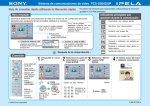
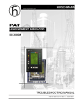
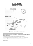
1
HIRSCHMANN
LOAD MOMENT INDICATOR
DS150
SERVICE MANUAL
P/N 031-300-100-753 REV C 08/22/03
Service Manual
DS150
NOTICE
Hirschmann, Inc. makes no warranty of any kind with regard to this material, including, but not limited
to, the implied warranties of merchantability and/or its fitness for a particular purpose.
Hirschmann, Inc. will not be liable for errors contained in this manual or for incidental or consequential
damages in connection with the furnishing, performance, or use of this manual. This document
contains proprietary information, which is protected by copyright, and all rights are reserved.
No part of this document may be photocopied, reproduced, or translated to another language without
the prior written consent of Hirschmann, Inc.
Hirschmann, Inc. reserves proprietary rights to all drawings, photos and the data contained therein.
The drawings, photos and data are confidential and cannot be used or reproduced without the written
consent of Hirschamnn, Inc. The drawings and/or photos are subject to technical modification without
prior notice.
All information in this document is subject to change without notice.
MANUAL REVISIONS
REV
A
B
C
DATE
10/16/01
03/08/02
08/22/032
NAME
CSH
CLC
CSH
DESCRIPTION
ECN 01-283
ECN 02-087
ECN 03-097
©2001 Hirschmann, Chambersburg, PA 17201, USA
© Hirschmann REV. B 03/08/02
100753_C.doc
Service Manual
DS150
TABLE OF CONTENTS
1
MECHANICAL DESCRIPTION OF THE SYSTEM COMPONENTS .............................................. 1
2
MECHANICAL AND ELECTRICAL DESCRIPTION OF THE CENTRAL UNIT ............................. 2
2.1
2.2
BASIC SYSTEM COMPONENT LAYOUT .......................................................................................... 3
BASIC ADJUSTMENT OF THE COMPONENTS ................................................................................. 4
3
DEFINITIONS .................................................................................................................................. 5
4
DRAWINGS ..................................................................................................................................... 6
4.1
4.2
4.3
4.4
4.5
4.6
5
PROCEDURE ................................................................................................................................ 16
5.1
5.2
5.3
5.4
6
ANTI-TWO BLOCK & SHUTOFF CIRCUIT ...................................................................................... 19
LENGTH MEASURING CHANNEL ................................................................................................. 19
PISTON SIDE PRESSURE MEASURING CHANNEL ......................................................................... 20
ROD SIDE PRESSURE MEASURING CHANNEL ............................................................................. 20
MAIN BOOM ANGLE MEASURING CHANNEL ................................................................................ 21
SECOND ANGLE MEASURING CHANNEL ..................................................................................... 21
TROUBLESHOOTING FLOW CHARTS....................................................................................... 22
7.1
7.2
7.3
7.4
7.5
7.6
7.7
7.8
7.9
7.10
8
EPROM REPLACEMENT IN CENTRAL UNIT ................................................................................. 16
PISTON & ROD PRESSURE CHANNEL ZERO POINT ADJUSTMENT ................................................ 16
LENGTH & ANGLE ADJUSTMENTS .............................................................................................. 17
MAIN BOARD REPLACEMENT ..................................................................................................... 18
THEORY ........................................................................................................................................ 19
6.1
6.2
6.3
6.4
6.5
6.6
7
SYSTEM ELECTRICAL DIAGRAM ................................................................................................. 6
CENTRAL UNIT 024-150-060-002 SPARE PARTS LIST .................................................................. 7
CONSOLE 050-150-060-006 SPARE PARTS LIST ......................................................................... 9
CONSOLE 050-150-060-008 SPARE PARTS LIST ....................................................................... 11
CABLE REEL 068-208-060-013 LWG208 SPARE PARTS LIST .................................................... 13
CENTRAL UNIT BOARD LAYOUT AND MEASURING POINTS 024-150-300-001 .............................. 15
GENERAL FLOWCHART .............................................................................................................. 22
LEVER LOCKOUT ACTIVATED ..................................................................................................... 23
BROKEN LENGTH CABLE ........................................................................................................... 24
NO DISPLAY .............................................................................................................................. 25
ANTI TWO BLOCK PROBLEM ...................................................................................................... 27
LENGTH READING PROBLEM...................................................................................................... 30
LOAD READING PROBLEM.......................................................................................................... 33
BAD DATA TRANSFER BETWEEN CONSOLE & CENTRAL UNIT ...................................................... 36
INTERFERENCE PROBLEM.......................................................................................................... 38
ANGLE PROBLEM ...................................................................................................................... 39
ERROR CODE TABLE.................................................................................................................. 40
ADDENDUM A BASIC ADJUSTMENT AND VOLTAGE CHECKS.................................................... 46
ADDENDUM B REFERENCE TABLES FOR MEASURING SUPPLY AND SIGNAL VOLTAGES FOR
SENSOR CHANNELS ......................................................................................................................... 47
© Hirschmann REV. B 03/08/02
100753_C.doc
Mechanical Description Of The System
1
1 MECHANICAL DESCRIPTION OF THE SYSTEM COMPONENTS
Pressure Transducer: The pressure transducer transforms hydraulic pressure into an electric analog
voltage signal. Two pressure transducers are connected, one to the rod side and one to the piston
side of the lift cylinder. The pressure transducer is connected to the central unit with a four-conductor,
double-shielded cable.
The power supply voltage is ± 5V.
The output signal is 0.00V under 0 pressure to -1.00V at max. pressure (4410psi)
The Length-Angle Transducer: The length-angle sensor (LWG) is a combination of two transducers
in one box, fitted at the base section of the boom. It measures the length and angle of the boom.
A reeling drum drives a potentiometer, which is the length transducer. Part of the length transducer is
the length cable on the drum, which is a two-conductor cable (screen and live). It is connected to the
anti-two-block switch at the boom head and to a slip ring body in the reel. The angle transducer is
fitted into a small box filled with oil. A pendulum drives the axle of the angle potentiometer.
The power supply voltage for both is -5.00V
The output signal for the length transducer is: -0.500V up to -4.500V
The output signal for the angle transducer is: -1.875V up to -3.125V
Anti-Two-Block Switch: The anti-two-block switch monitors the load block and its relationship with
the head of the boom. In working condition, the switch is closed. When the hook block strikes the
weight, the circuit opens, disengaging a relay output to the lockout solenoid valves, where applicable.
To check the cable for damage, (short circuit to ground) there is a 4.7k resistor between ground and
the contact of the switch. The weight at the anti-two-block switch keeps the switch closed until the
hook block strikes it.
Console: The console displays the geometrical information such as length and angle of main boom,
working radius and head height of the boom. It also displays the actual load and the maximum load
permitted by load chart. Furthermore, it has an alarm horn and a warning light for overload, and a prewarning light. The analog instrument shows a percentage of the total permissible moment. The
console has a switch for the operating modes (duty-selection switch for crane configurations) and a
switch for the Reeving of the hook block. It also has a warning light for anti-two-block conditions and
an override switch for overload or anti-two block condition.
Duty Selection Switches (Digital Inputs): The system has to be programmed for the lifting area
configuration. The crane is going to be worked in (e.g. main boom) on outriggers over front, or rear, or
over the side for 360 degrees. For obtaining this information from the crane, micro switches are
installed in the electrical swivel that tells the system the exact location of the boom. Micro switches
are also located on the counterweight which tells the system if the counterweight is installed or not,
where applicable.
© Hirschmann REV. B 03/08/02
100753_C.doc
2
Service Manual
DS150
2 MECHANICAL AND ELECTRICAL DESCRIPTION OF THE CENTRAL UNIT
All the data of the crane is stored inside the central unit in EPROM’s. The central unit receives all
actual information of the crane. This is computed against the reference data and the crane status is
continuously monitored.
Description of the Housing: The central unit DS150 is a rugged, waterproof sheet steel housing. It is
mounted on the left side of the turn table weldment or on the counterweight. The cables are led into
the central unit via strain reliefs and connected with fast-ons. An override switch is mounted on the
housing, which overrides the LMI function. The system is protected by a 2-AMP fuse, which is
mounted on the lower right side. The output signal is protected by a 10-AMP fuse, mounted on the
lower mid.
Description of the Boards: Inside the central unit (CU) there is a main board. The main board and
CPU is the heart of the system, and it contains the processor and the system and data EPROMs. The
system EPROM holds the operating system and data EPROM hold the crane and calibration
information. The wires from the various components are connected with fast-ons to the main board.
The main board holds the electronics necessary to receive, evaluate, and direct the continuous flow of
data from the sensors to the processor.
Main board components:
Power supply: Provides all the necessary voltages for the transducers and the electronics on the main
board.
Analog input part: Receives and prepares all the signals from the transducers for further processing.
Relays, an overload and anti-two-block relay: Controls the Bosch relay for lever lockout.
Incoming Signals: Signals from the transducers are connected to the main board. The signals vary
depending on the sensor:
Angle transducer signal is between -1.875V and -3.125V.
Length transducer signal is between -0.500V and -4.500V.
Pressure transducer signals are between 0.00V and -1.00V. (measured between the negative and
positive outputs)
Anti-two-block switch resistance is 4.7Kohms.
Digital inputs for the duty selection switches are on or off.
Outgoing Signal: The outgoing signal of the main board is the signal for lever lockout of connection
#48. In normal working conditions there are 12 volts at this connection. If there is an overload or antitwo-block condition the signal becomes 0 volts. Furthermore, all voltages for the transducers are going
out through the main board.
© Hirschmann REV. B 03/08/02
100753_C.doc
Mechanical Description Of The System
2.1
3
Basic System Component Layout
© Hirschmann REV. C 08/22/03
100753_C.doc
4
2.2
Service Manual
DS150
Basic Adjustment Of The Components
Length: Ensure that the length cable tension is correct with fully retracted boom and no tension on the
cable reel. Turn the cable drum 5 to 8 turns counter clockwise. Then remove cover from cable reel
and adjust the potentiometer counter clockwise to end stop. See Procedure 3.
Angle: Set the boom between 0 and 5 degrees and set the inclinometer to the boom angle. Adjust
the angle sensor to the same angle as the boom. Check the angle at 20 degrees, 45 degrees, and 70
degrees. Angle display should be less than ± .5 degrees of the value of the inclinometer. See
Procedure 3.
Pressure Channel: Rest the boom and disconnect hydraulic hoses from the pressure transducers.
Measure and record the zero-points of both pressure transducers on the main board. Adjust P1 and
P2 on the main board to 500mV at test points MP11 and MP12. Connect hydraulic hoses back to the
pressure transducers. See Procedure 2.
Duty Selection Switches Digital Inputs): Check the duty selection switches for correct operation.
Check the voltage on digital input connections.
Check the function of the hoist limit switch (anti-two-block)
Check function of lever lockout.
Measure and record the power supply voltages. See Addendum A.
© Hirschmann REV. C 08/22/03
100753_C.doc
Definitions
5
3 DEFINITIONS
BOOM LENGTH: The straight line through the centerline of boom pivot pin to the centerline of the
boom point load hoist sheave pin, measured along the longitudinal axis of the boom. (Indicator ± 2%)
BOOM ANGLE: The angle between the longitudinal centerline of the boom base section and the
horizontal plane. (Indicator 65° to 90° boom angle + 0°/2°; less than 65° boom angle + 0°/-3°)
RADIUS OF LOAD The horizontal distance from a vertical projection of the crane’s axis of rotation to
the supporting surface, before loading, to the center of the vertical hoist line or tackle with rated load
applied. (Indicator 100% to 110%)
RATED LOAD The load value shown on the applicable load-rating chart of the crane for the particular
crane configuration, boom length, boom angle, or functions or these variables. For radii outside those
shown on the load-rating chart, the rated load is to be considered as zero.
ACTUAL LOAD The weight of the load being lifted and all additional equipment such as blocks,
slings, sensors, etc. Also referred to as working load. (Indicator 100% to 110%)
CRANE CONFIGURATION The physical arrangement of the crane which is prepared for a particular
operation in conformance with the manufacturer’s operating instructions and load rating chart.
TWO-BLOCKING Contact of the lower load block or hook with the upper load block, boom point, or
boom point machinery.
ANALOG: Electrical signals that vary in proportion to the quantities they represent. (Boom length,
angle, and pressure transducer)
DIGITAL: Electrical signals of an on-and-off state (two different voltage levels) to represent some
quantity of operation. (A2B, area definition switch)
© Hirschmann REV. B 03/08/02
100753_C.doc
6
Service Manual
DS150
4 DRAWINGS
4.1
SYSTEM Electrical Diagram
© Hirschmann REV. B 03/08/02
100753_C.doc
Drawings
4.2
7
Central Unit 024-150-060-002 Spare Parts List
© Hirschmann REV. C 08/22/03
100753_C.doc
8
Service Manual
DS150
PART NO. 024-150-060-002 CENTRAL UNIT, DS150/0002 STANDARD PARTS LIST
NO.
01
02
03
04
05
06
07
08
09
10
11
12
13
14
15
16
17
18
19
20
21
22
23
24
PART NO.
024-150-300-001
024-350-100-135
024-000-100-041
024-350-100-139
024-150-100-001
024-350-100-661
031-300-101-131
024-350-110-067
000-314-022-006
000-313-062-001
000-313-062-002
000-304-140-122
024-350-110-066
021-441-161-213
050-350-110-116
000-214-340-011
000-214-210-011
000-214-340-013
000-214-210-013
000-214-340-016
000-214-210-016
024-150-100-002
031-300-100-078
024-150-110-002
© Hirschmann REV. C 08/22/03
QTY
1
1
1
1
1
1
1
2
2
1
1
1
1
1
1
4
4
1
1
1
1
1
1
1
DESCRIPTION
BOARD, MAIN, DS150, CU, 12V
CENTRAL UNIT ACCY, SCREW SET, DS150
CENTRAL UNIT ACCY, GROUNDING KIT FOR COVER
CENTRAL UNIT ACCY, WALL MOUNT SET, DS150/350
HOUSING, CENTRAL UNIT, DS150
KEYSWITCH, CENTRAL UNIT, NEW STATIONARY
KEY ASSY, ONE OLD STYLE KEY/ONE NEW STYLE KEY
STRAIN RELIEF ASSY, PG 11, GRN W/NUT+WASHER
FUSE HOLDER, CENTRAL UNIT,MAIN BOARD
FUSE, 2 AMP 1/4 x 1 1/4, 250V FAST-ACTING
FUSE, 10 AMP 1/4 x 1 1/4, 250V FAST-ACTING
RELAY, SHUT-OFF 12 V (BOSCH)
CENTRAL UNIT ACCY, GASKET, FOR C.U. COVER
STRAIN RELIEF, PG 13.5,12-15mm GRY/WHT INSERT
STRAIN RELIEF ASSY, PG 13.5 RED, W/NUT+WASHER
STRAIN RELIEF ACCY, PG11 HOLE PLUG
NUT, PG11
STRAIN RELIEF ACCY, PG13.5 HOLE PLUG
NUT, PG13.5
STRAIN RELIEF ACCY, PG16 HOLE PLUG
NUT, PG16
CENTRAL UNIT ACCY, BASEPLATE, DS150
CHEMICAL, MOISTURE PACK
COVER, CENTRAL UNIT, DS150
100753_C.doc
Drawings
4.3
9
Console 050-150-060-006 Spare Parts List
To change DS150/0006 (12V) to DS150/0036 (24V) a jumer wire must be soldered on main board, J3
added, and the ligth bulbs changed. When ordering spare part please specify 12 or 24 volt machine.
© Hirschmann REV. C 08/22/03
100753_C.doc
10
NO.
01
02
03
04
05
06
07
07
08
09
10
11
12
13
14
15
16
17
18
19
20
21
22
23
23
Service Manual
PART NO.
050-150-300-003
050-350-110-292
050-000-100-060
050-350-110-116
000-305-045-141
003-051-405-423
000-311-023-114
000-311-023-128
050-350-110-277
050-350-110-278
050-350-110-279
050-350-110-280
050-350-110-281
050-350-110-282
050-350-110-283
003-051-903-364
050-350-110-139
050-000-110-007
050-150-100-006
000-209-022-095
050-000-100-092
050-150-110-005
050-000-110-014
050-000-700-301
024-350-100-312
© Hirschmann REV. C 08/22/03
QTY
1
1
1
1
2
5
7
7
1
1
1
1
1
1
1
1
1
1
1
850mm
1
1
3
2
1
DS150
DESCRIPTION
CONSOLE BOARD W/ROTARY SWITCH - DS150
LCD DISPLAY DS150
CONSOLE HOUSING W/LID
STRAIN RELIEF/LONG RED
LUMINOUS HOUSING
LUMINOUS PUSH BUTTON HOUSING
LIGHT BULB 12V
LAMP, SPARE LIGHT BULB 28V
CAP A2B (RED)
CAP PREWARNING (YELLOW)
CAP STOP/ALARM OFF (RED)
CAP LOAD (ORANGE)
CAP INFO (ORANGE)
CAP ANGLE (ORANGE)
CAP ENTER (GREEN)
KEY SWITCH
CONSOLE OVERRIDE KEY DS150/350
ALARM BUZZER
FRONT PANEL
GASKET FOR FRONT PANEL
CONSOLE LID DS150/0006
GASKET FOR LID
LATCH ASSEMBLY
KNOB FOR ROTARY SWITCH
LABYRINTH MOISTURE ELEMENT
100753_C.doc
Drawings
4.4
11
Console 050-150-060-008 Spare Parts List
To change DS150/0008 (12V) to DS150/0012 (24V) a jumer wire must be soldered on main board, J3
added, and the ligth bulbs changed. When ordering spare part please specify 12 or 24 volt machine.
© Hirschmann REV. C 08/22/03
100753_C.doc
12
NO.
01
02
03
04
05
06
07
08
09
09
10
11
12
13
14
15
16
17
18
19
20
21
22
23
24
PART NO.
050-150-300-003
050-350-110-292
050-000-100-048
050-150-110-001
050-350-110-183
050-350-110-116
000-312-043-141
003-051-403-423
000-311-023-114
000-311-023-128
050-350-110-074
050-350-110-073
050-350-110-075
050-350-110-076
050-350-110-077
050-350-110-078
050-350-110-079
003-051-903-364
050-350-100-001
050-150-110-002
050-350-110-140
050-350-110-049
050-150-100-008
050-000-050-309
002-053-703-101
Service Manual
QTY
1
1
1
1
2
1
2
5
7
7
1
1
1
1
1
1
1
1
1
1
1
1
1
1
1
© Hirschmann REV. C 08/22/03
DS150
DESCRIPTION
BOARD, MAIN, DS150 CONSOLE 12V FOR 4x20mm DISPLAY
INDICATOR, DISPLAY, LCD, DS150 CONSOLE
HOUSING, DS150 CONSOLE, COMPLETE
BRACKET, CONSOLE, DS150 COMPLETE
KNOB, MOUNTING KNOB
STRAIN RELIEF ASSY, PG 13.5 RED/WHITE W/NUT+WASHER
LAMP ACCY, PILOT,BASIC HOUSING
SWITCH, PUSHBUTTON w/o LENS & BULB
LAMP, SPARE LIGHT BULB 12V
LAMP, SPARE LIGHT BULB 28V
SWITCH ACCY, LENS CAP, RED (A2B)
SWITCH ACCY, LENS CAP, YELLOW (PREWARNING)
SWITCH ACCY, LENS CAP, RED (STOP/BUZZER OFF)
SWITCH ACCY, LENS CAP, ORANGE (LOAD)
SWITCH ACCY, LENS CAP, ORANGE (INFO)
SWITCH ACCY, LENS CAP, ORANGE (ANGLE)
SWITCH ACCY, LENS CAP, GREEN (ENTER)
KEYSWITCH W/KEYS, CONSOLE DS150
KEY, CONSOLE KEYSWITCH
SWITCH ACCY, KNOB WITH SCALE DISK 1-63
SWITCH ACCY, KNOB WITH SCALE DISK 1-16
ALARM, BUZZER, DS150 & DS350C CONSOLE
FACEPLATE, DS150 CONSOLE, LARGE DISPLAY (STD.)
GASKET, HOUSING
SCREW, 3mm x 10mm, PANHEAD, PHILLIPS FACEPLATE
100753_C.doc
Drawings
4.5
13
Cable Reel 068-208-060-013 LWG208 Spare Parts List
© Hirschmann REV. C 08/22/03
100753_C.doc
14
Service Manual
NO.
01
02
03
04
05
06
07
08
09
10
11
PART NO.
006-710-006-002
068-000-110-038
067-000-050-065
064-103-060-002
002-050-206-012
000-207-010-064
002-050-206-100
000-208-040-083
068-000-100-064
068-000-110-029
068-000-100-152
12
13
14
15
16
17
18
19
20
21
068-000-110-011
000-673-020-002
006-800-005-058
000-205-031-230
006-800-005-057
005-682-000-001
068-000-110-031
000-208-020-006
021-441-131-013
000-214-030-703
© Hirschmann REV. C 08/22/03
DS150
QTY
1
1
1
1
2
3
1
1
1
1
1
DESCRIPTION
SENSOR, LENGTH TRANS. LGE 100 (KT200/LWG208)
SENSOR ACCY, GEAR WHEEL, KT200 CABLE REEL
SENSOR ACCY, GEAR WHEEL, T=50 CENTER SHAFT
SENSOR, ANGLE WG103
SCREW, 6M X 12 SOCKET CAP
WASHER, FLAT 6MM
SCREW, 6M x 100M SOCKET CAP
WASHER, LOCK 6MM
SLIPRING, 2 CONDUCTOR
CONNECTION STRIP
CABLE REEL, KT200 HOUSING,BKT,CABLE DRUM & NYLON
CABLE COVER
1
CABLE REEL ACCY, CABLE DRUM,KT 200/ LWG208
139' CABLE, LENGTH SENSOR, 1 CORE W/SHEILD (per ft)
1
BRACKET, MTG. CABLE REEL ARM, ONE SLOT
4
SCREW, 12mm x 30MM HEX HEAD
1
BRACKET, MTG. CABLE REEL ARM, TWO SLOTS
1
COVER, CABLE REEL, KT200
10 CABLE REEL ACCY, SCREW CABLE REEL COVER
10 WASHER, LOCK 6mm
1
STRAIN RELIEF, PG 13.5, 8-12mm RED+WHITE
1
STRAIN RELIEF, PG7 BLACK
100753_C.doc
Drawings
4.6
15
Central Unit Board Layout And Measuring Points 024-150-300-001
Measuring Points
MP1: AGND
MP2: +9V
MP3: -9V
MP4: 5V TTL
MP5: 5V REF
MP6: +5V/+UPS sensors supply
MP7: -5V/-UPS sensors supply
MP8: +9V HES
MP10: AGND
MP11: DAV1 piston pressure signal
MP12: DAV2 rod pressure signal
MP13: LW1 length signal
MP14: WG1 angle signal #1
MP15: WG2 angle signal #2
LED's
LOAD: Overload relay ON(energized/normal conditions)/OFF (de-energized)
A2B: A2B relay ON(energized/normal conditions)/OFF (de-energized)
© Hirschmann REV. C 08/22/03
100753_C.doc
16
Service Manual
DS150
5 PROCEDURE
5.1
EPROM replacement in Central Unit
Follow this procedure when changing EPROM’s in the DS150 central units.
1. Remove cover, from central unit.
CAUTION: Before handling the EPROM, discharge any static electricity from your body by touching a
ground source. The EPROM could be damaged if this procedure is not followed.
Use the central unit main board layout and measuring point drawing to locate the system and data
EPROM’s.
2. Remove the old EPROM from the main board using an EPROM puller. Be careful not to bend the
legs of the EPROM when removing it.
3. Installing the new EPROM:
• Ensure the notch is in the correct direction. The direction of the EPROM is determined by the notch on the
end of the EPROM.
• The DATA and TLK EPROM’s fill the bottom of the socket as shown by the arrows.
• Place EPROM in the correct EPROM socket as shown.
4. Inspect gasket and install cover using the following procedures to prevent any moisture from
entering the central unit.
Reference material:
031-300-340-002 Central Unit Cover Installation and Tightening Procedure; Rev A.
031-300-340-003 Central Unit Gasket Recommendations; Rev -.
5.2
Piston & Rod Pressure Channel Zero Point Adjustment
Use the central unit main board layout and measuring point drawing to make the following
adjustments.
1. Lower boom all the way down (no rest pressure) then disconnect hydraulic hose from the piston
side pressure transducer.
2. Connect a digital voltmeter to main board
A) black (-) lead to mp10
B) red (+) lead to mp11
3. Adjust P1 to obtain a reading of 0.500 volts (500mv) on meter.
4. Disconnect hydraulic hose from the rod side pressure transducer.
5. Connect a digital voltmeter to main board
A) BLACK (-) lead to MP10
B) RED (+) lead to MP12
6. Adjust P2 to obtain a reading of 0.500 volts (500mv) on meter.
7. Reconnect hydraulic hoses to pressure transducers, and then bleed the air from hydraulic lines.
©PAT REV. B 03/08/02
100753_C.doc
Procedures
5.3
17
Length & Angle Adjustments
© Hirschmann REV. C 08/22/03
100753_C.doc
18
5.4
Service Manual
DS150
Main Board Replacement
Refer to Drawing 1, central unit parts list for board location.
1. Turn system power off.
2. Remove the central unit lid.
NOTE: Take care not to damage the boards with the screwdriver, when removing and inserting
screws.
3. Remove the system and data software from the main board.
4. Remove the relay from the main board.
5. Mark all connection wires before removing, to identify location for reconnecting. Disconnect all X1
terminal wires from the main.
6. Remove the 9 large Philips screws holding the main board in place.
7. Note the orientation of the main board in the central unit. Remove main board and place it in the
same packing material that the replacement in which the main board came.
8. Carefully insert the new main board in place.
9. Insert the 9 Philips mounting screws.
10. Insert the relay into the main board.
11. Insert the system and data software into the main board.
12. Connect the X1 terminal wires to the main board. Refer to Wiring Diagram.
13. Zero pressure transducers using the zeroing procedure in this section.
14. Inspect the gasket for nicks, cuts, or damages. Refer to 031-300-340-003 DS 350 Central Unit
Gasket Recommendations, Revision - and 031-300-340-002 Central Unit Cover Installation and
Tightening Procedure, Revision A
© Hirschmann REV. C 08/22/03
100753_C.doc
Theory
19
6 THEORY
6.1
Anti-Two Block & Shutoff Circuit
6.2
Length Measuring Channel
©PAT REV. B 03/08/02
100753_C.doc
20
Service Manual
6.3
Piston Side Pressure Measuring Channel
6.4
Rod Side Pressure Measuring Channel
© Hirschmann REV. C 08/22/03
DS150
100753_C.doc
Theory
6.5
Main Boom Angle Measuring Channel
6.6
Second Angle Measuring Channel
© Hirschmann REV. C 08/22/03
21
100753_C.doc
22
Service Manual
DS150
7 TROUBLESHOOTING FLOW CHARTS
7.1
General Flowchart
This section explains how to handle a problem that may arise with the PAT Load Moment Indicator
System-PAT DS150. The procedures are easy to follow and are given in flowcharts on the following
pages. Start with the general flowchart below, which will guide you to one of the detailed flowcharts
shown in this section.
START
What’s Wrong?
Lever Lockout Activated
Go to Flow Chart 2
Broken Length Cable
Go to Flow Chart 3
No display
Go to Flow Chart 4
Anti-Two Block Problem
Go to Flow Chart 5
Length Reading Problem
Go to Flow Chart 6
Load Reading Problem
Go to Flow Chart 7
Bad Data Transfer Between
Console & Central Unit
Go to Flow Chart 8
Interference Problem
Go to Flow Chart 9
Angle Problem
Go to Flow Chart 10
©PAT REV. B 03/08/02
100753_C.doc
Troubleshooting Flow Charts
7.2
23
Lever Lockout Activated
PROBLEM: The lever lockout system of the crane is activated. Crane movements “hoist up”, “telescope
out”, and “boom down” are stopped. Crane is not in overload or two-block condition.
Start
Set the override key switch in central unit into upper position to override
LMI. Refer to Operator’s Handbook for LMI override instructions.
Fixed
YES
NO
Does console indicate Anti-Two-block warning?
NO
Yes
Fault in crane electric
or hydraulic system.
If console display is
blank fault is located in
power supply, wiring or
fuses .
Fault in Anti-Two
Block system.
Check lever lockout
system in crane.
Go to Flow Chart 4
Go to Flow Chart 5
© Hirschmann REV. C 08/22/03
If Load Moment Limit Light
displays fault, it is located in
LMI, cables, wiring, fuses, or
console.
Read error code displayed
on console and go to
Section 6.
100753_C.doc
24
7.3
Service Manual
DS150
Broken Length Cable
PROBLEM: Damaged or broken length cable.
Refer to cabel reel parts list and system wiring diagram.
Replace length cable using the following procedure:
1
2
3
4
5
6
7
8
9
10
11
12
13
14
Cut old cable at cable drum
Disconnect damaged length cable from junction box at the boom nose.
Open cable reel cover and disconnect wiring from connection block. Pull 7 conductor cable out of
strain relief.
Remove cable reel from mounting brackets.
Remove damaged length cable, which is mounted to the slip rings in the cable reel, from slip ring
connection.
On the backside of the cable reel, open the strain relief attached to the axle in the center of the
drum. Pull existing length cable out of the cable reel.
Pull new length cable through the hole, pipe and strain relief and push it through the axle of the
reeling drum. Tighten strain relief to ensure sealing.
Reconnect the length cable to the slip ring.
Remount cable reel to the boom.
Turn reeling drum clockwise to spool the new cable neatly onto the drum.
Set preload on cable reel by turning the drum counter-clockwise 5 to 8 turns.
Wrap the new length cable around the boom tip anchor pin (4 or 5 wraps) and secure with tie
wraps. Leave enough length cable to connect into the boom tip junction box.
Connect the length cable into the boom tip junction box.
Reset length potentiometer in length angle transducer (screw is located in center of white gear);
with boom fully retracted, turn potentiometer carefully counter-clockwise until it stops. Recheck
length and angle display.
© Hirschmann REV. C 08/22/03
100753_C.doc
Troubleshooting Flow Charts
7.4
25
No Display
PROBLEM: Blank console display with no warning light shown. All crane moments
have been stopped.
Start
Check fuses on CPU box.
Correct?
No
Replace fuses.
Yes
Measure crane voltage on connection board between X1-2 (+12V) and X1-4 (ground).
Refer to system wiring diagram.
NOTE: If crane voltage is measured below 10V system will switch off.
Correct?
No
Check crane power supply for faulty
crane electric or if supply is too low.
Yes
Measure voltage on the connection board between X1:30 (+12/24V) and X1:33
(ground). This is an output voltage to the console.
Refer to system wiring diagram.
Correct?
No
Replace connection board and reset pressure
channel. Refer to system wiring diagram and
main board replacement procedure.
Yes
Next Page
© Hirschmann REV. C 08/22/03
100753_C.doc
26
Service Manual
DS150
PREVIOUS PAGE
Measure voltage in the console between X1:1 (+12/24V) and X1:2 (ground).
Refer to system wiring diagram.
Correct?
NO
Check connections of the cable between
console and central unit. Replace cable if
necessary. Refer to system wiring diagram.
YES
Display is defective.
Refer to console parts list.
YES
END
© Hirschmann REV. C 08/22/03
100753_C.doc
Troubleshooting Flow Charts
7.5
27
Anti Two Block Problem
PROBLEM: Function of Anti-Two-Block System is faulty.
START
Check to see whether or not crane is in two-block condition.
Correct?
No
Lower hook down into safe position
Yes
Check if jumper/dummy plug in receptacle at boom nose is plugged in.
Refer to system wiring diagram.
Correct?
No
Plug appropriate plug into socket of junction box.
Yes
Turn power off or disconnect wire from connection board X1:35 in central unit. Remove
bypass plug and check function of Anti-Two Block switches with
ohmmeter between wires 2 and 3 of switches or between terminals 1 and 6 at boom nose
box. This checks the function of the Anti-Two Block switch. Install bypass plug.
Switch closed = 0 Ohm (weight installed)
Switch open => 1 Megaohm (weight removed)
Refer to system wiring diagram.
Correct?
No
Replace Anti-Two-Block switch.
Yes
Next Page
© Hirschmann REV. C 08/22/03
100753_C.doc
28
Service Manual
DS150
PREVIOUS PAGE
Measure the A2B signal in the cable reel between X1:Brown and X2:Red
wires on the slip ring with an ohmmeter.
Switch closed =4700 ±500Ohms
Switch open => 1 Megaohm
Reconnected slip ring wires.
Refer to system wiring diagram.
Correct?
No
Fault in wiring between boom nose box and cable reel.
Check for damaged length cable and wiring.
Refer to system wiring diagram.
If broken length cable, Refer to length cable replacement.
Measure the A2B signal in the cable reel between terminal 7 and 8 with an ohmmeter.
Switch closed =4700 ±500Ohms
Switch open => 1 Megaohm
Reconnected slip ring wires.
Refer to system wiring diagram.
Correct?
No
Replace slip ring
Refer to cable reel parts list.
Measure the A2B signal in the boom base 10 pin receptacle between terminal 5 and 6
with an ohmmeter.
Switch closed =4700 ±500Ohms
Switch open => 1 Megaohm
Reconnected slip ring wires.
Refer to system wiring diagram.
Correct?
No
Fault in 7 conductor cable between cable reel and
boom base box.
Refer to system wiring diagram.
NEXT PAGE
© Hirschmann REV. C 08/22/03
100753_C.doc
Troubleshooting Flow Charts
29
PREVIOUS PAGE
Connect wire #5 back to the terminal X1:35 on the connection board.
Refer to system wiring diagram.
Turn system power off. Check Anti-Two-Block signal in central unit with ohmmeter
measure between X1:34 and X1:35.
Anti-Two-Block switch closed = 4700 Ohms ±50 0Ohms
Anti-Two-Block switch open => 1 Megaohm.
Refer to system wiring diagram.
Correct?
Faulty wiring between cable reel and central unit.
Check cable.
NO
YES
Disconnect X1:34 and X1:35. Check main board function by installing a temporary
resistor, 4700 Ohms between X1-34 and X1-35 in central unit. With resistor connected
alarm should be inactive.
Refer to system wiring diagram.
Correct?
NO
Replace main board and reset pressure channel.
Refer to main board replacement procedure .
Reconnect Wire #6 to X1:34 and Wire #5 to X1:35
Refer to system wiring diagram.
End
© Hirschmann REV. C 08/22/03
100753_C.doc
30
7.6
Service Manual
DS150
Length Reading Problem
PROBLEM: Length reading incorrect. Crane is not in “out of load chart” condition.
START
Check mechanical adjustment of length potentiometer in cable reel. When main boom is fully retracted,
adjust length potentiometer counter-clockwise until it stops.
Refer to length/angle adjustments procedure.
Correct?
No
Replace length potentiometer assembly. Remove slip ring body from shaft and
remove gear wheel from potentiometer axle. Unscrew mounting plate and
remove potentiometer assembly from mounting plate. Remove assembly wires
form terminal block. Connect new assembly to terminal block. Reinstall
mounting plate, gear wheel and slip rings. With boom fully retracted, reset
potentiometer by turning counter-clockwise until it stops.
Refer to Cable Reel Parts List.
Yes
Check out clutch in big gear wheel of length transducer. Extend and retract
boom to ensure that clutch is not sipping on potentiometer axle.
Correct?
No
Replace the gear wheel, clean potentiometer
axle. Reset length potentiometer.
Refer to length/angle adjustments procedure.
Yes
Check power supply to length transducer on connection board,
terminal X1:8 (ground) and X1:11 (-5V)
Refer to system wiring diagram.
Correct?
No
Replace connection board and reset pressure
channel. Refer to system wiring diagram and main
board replacement procedure.
Yes
NEXT PAGE
© Hirschmann REV. C 08/22/03
100753_C.doc
Troubleshooting Flow Charts
31
Continued from previous page.
PREVIOUS PAGE
Measure supply to length transducer in cable reel at terminal between Pin 1 (ground)
and Pin 3 (-5v)
Refer to system wiring diagram.
Correct?
No
Faulty wiring between central unit and
length transducer. Check wiring.
Yes
Measure signal from length transducer in cable reel between pin 2(signal) and pin 1(ground).
Retracted boom, with no turns on the potentiometer, signal is -0.500v
At 10 turns on the potentiometer the signal measurement would be -4.500v.
Therefore the voltage of an extended boom will be between -0.500 to -4.500 volts .
Correct?
No
Replace length potentiometer assembly. Remove slip ring body from shaft and
remove gear wheel from potentiometer axle. Unscrew mounting plate and
remove potentiometer assembly from mounting plate. Remove assembly wires
form terminal block. Connect new assembly to terminal block. Reinstall
mounting plate, gear wheel and slip rings. With boom fully retracted, reset
potentiometer by turning counter-clockwise until it stops.
Yes
Measure signal from length transducer in central unit main board between X1:8 (ground) and X1:10
(signal: -0.5 and -4.5v) Refer to system wiring diagram.
Correct?
No
Faulty wiring between central unit and length
transducer. Check wiring.
Yes
NEXT PAGE
© Hirschmann REV. C 08/22/03
100753_C.doc
32
Service Manual
DS150
Continued from previous page.
PREVIOUS PAGE
Measure length signal of amplified output on connection board between test
point MP10 and test point MP13. (+5V)
NOTE: Negative signal at terminal X1:11 will be converted into positive signal
at MP13 (i.e.: input at terminal X1:11 = -0.5V and gnd).
Refer to system wiring diagram.
Correct?
No
Replace connection board and reset pressure channel.
Refer to system wiring diagram and main board
replacement Procedure.
Yes
END
© Hirschmann REV. C 08/22/03
100753_C.doc
Troubleshooting Flow Charts
7.7
33
Load Reading Problem
PROBLEM: Load reading incorrect.
START
Check selected operating mode (code on operating mode switch).
Correct?
Select operating mode switch to correct position
(see operating mode in load chart).
No
Yes
Check boom length reading on display.
Correct?
No
Reset length potentiometer. With fully retracted boom, turn potentiometer
axle counter-clockwise until it stops (see Section 3 and 6).
Refer to length & angle adjustments procedure.
Yes
Measure radius and check with the displayed radius.
Correct?
No
Check mechanical adjustment of angle transducer is correct. Angle transducer
box should be in line with boom and adjusted to actual boom angle should
match displayed boom angle.
Refer to length & angle adjustments procedure.
YES
Check power supply to pressure transducer (rodside). Unplug transducer cable from transducer.
Measure connection board between X1:14 to X1:13 (-5.0v) and X1:14 to X1:15 (+5.0) for rod side
Check power supply to pressure transducer (piston side). Unplug transducer cable from transducer.
Measure connection board between X1:19 to X1:20 (-5.0v) and X1:19 to X1:18 (+5.0)
Refer to system wiring diagram.
NEXT PAGE
© Hirschmann REV. C 08/22/03
100753_C.doc
34
Service Manual
DS150
Pervious Page
Correct?
No
Check power supply and measure between test point MP10 (ground) to
MP7(+5.0v) and between test point MP10 (ground) to MP6(-5.0v)
Refer to main board layout.
Correct?
Yes
Check power supply and measure between test point MP10 (ground) to
MP2(+9.0v) and between test point MP10 (ground) to MP3(-9.0v)
Refer to main board layout.
Yes
Correct?
Yes
Power supply on connection board faulty. Replace connection board and reset
pressure channel. Refer to system wiring diagram and main board
replacement procedure.
Check power supply at transducer plugs.
Measure between B (ground) and A = +5V.
Measure between B (ground) and C = -5V.
Correct?
No
Faulty wiring. Check wiring of pressure transducer cable.
Yes
NEXT PAGE
© Hirschmann REV. C 08/22/03
100753_C.doc
Troubleshooting Flow Charts
35
PREVIOUS PAGE
Check transducer signals in central unit. Connect pressure transducers to cable.
Disconnect wire No. 4 of transducer cable from X1:21 (signal piston side).
Measure transducer signals (0. . .-1V) between Pin 19 (ground) and wire No. 4 of piston cable.
Disconnect wire No 4 of transducer cable from terminal block X1: Pin 16 (single rod side).
Measure transducer signals (0. . .-1V) between Pin 19 (ground) and wire No. 4 of rod cable.
Refer to system wiring diagram.
Correct?
No
Check wiring in pressure transducer cable. Continuity Good?
No
Correct?
Yes
Transducer defective-replace transducer and reset pressure channel.
Yes
Connect wire No. 4 from transducer cables back to terminal X1:16 (rod side) and terminal X1:21(piston
side). Without pressure in pipes or hydraulic pipes disconnected from transducer, check 0-point
adjustment on connection board.
Measure between test point MP10 (ground) and test point MP11. Signal should be 0.50V (piston side).
Measure between test point MP10 (ground) and test point MP12. Signal should be 0.50V (rod side).
Refer to system wiring diagram.
Correct?
No
Measure voltage between test point MP10 (ground) and test point MP11
and reset with P1 to 0.50V (piston side).
Measure voltage between test point MP10 (ground) and test point MP12
and reset with P2 to 0.50V (rod side).
If not adjustable, replace transducer.
Refer to system wiring diagram and zeroing transducer procedure.
END
© Hirschmann REV. C 08/22/03
100753_C.doc
36
7.8
Service Manual
DS150
Bad Data Transfer Between Console & Central Unit
PROBLEM: Error Code “E93/E94" No data transfer to and from console.
START
Make sure that the eproms are plugged into the correct socket and orientated.
Refer to EPROM replacement procedure.
Correct?
No
Place EPROM in correct socket.
Yes
Check crane supply voltage for console in central unit at connection board X: 33 (ground) and X1:30
(+12V). Make sure external and internal power supply is correct. Refer to Section 4.
Refer to system wiring diagram.
Correct?
No
Replace main board and reset pressure channel. Refer to
system wiring diagram and transducer replacement
procedure .
Yes
NEXT PAGE
© Hirschmann REV. C 08/22/03
100753_C.doc
Troubleshooting Flow Charts
37
Continued from previous page
PREVIOUS PAGE
Check power supply to console between console terminal 2(ground) and terminal 1 (+12v)
Refer to system wiring diagram.
Correct?
No
Faulty wiring in cable from central unit to console.
Replace cable.
Yes
Ensure that wires are properly connected between CU X1:31 and console terminal 4 and
between CU X1:32 and console terminal 3.
Refer to system wiring diagram.
Correct?
No
Replace main board and reset pressure channel.
Refer to system wiring diagram and transducer replacement
procedure.
Yes
END
© Hirschmann REV. C 08/22/03
100753_C.doc
38
7.9
Service Manual
DS150
Interference Problem
PROBLEM: Interference from crane
electric. Error Code “E93/E94"
intermittent. Frozen console displays.
START
Refer to Section 8 - Bad Data
Transfer Between Console & Central Unit.
Correct?
No
Replace or repair part which is defective.
Yes
Check if additional ground link between main
board terminal X1:3 and central unit box mounting bracket is in place.
Correct?
Install ground line - single cable minimum of AWG14 (2.0mm ) between
terminal X1:3 and central unit box mounting bracket.
Refer to system wiring diagram.
No
Yes
Ensure that cable shields are connected correctly. Refer to connection and
wiring diagrams, Refer to system wiring diagram.
Correct?
Make correct shield connection.
Refer to system wiring diagram.
No
Yes
Find out which component of the crane electric is spiking out (e.g. dump valve, outrigger relay). Install a
diode or resistor across terminals of spiking component. Diode type such as 1N4001 can be used,
however, ensure the correct plus and minus connections for diode.
END
© Hirschmann REV. C 08/22/03
100753_C.doc
Troubleshooting Flow Charts
39
7.10 Angle Problem
PROBLEM: Displayed Angle Incorrect. Actual measured angle is different from displayed angle.
START
Use a calibrated inclinometer to measure the actual main boom angle
and compare with displayed angle on console.
Refer to length/angle adjustments procedure.
Check the supply voltage to angle sensor on connection board
between X1:11 (+5VDC) and X1:8 (ground).
Refer to system wiring diagram.
Correct?
Check system power supply voltage.
Refer to Section 7.4 No Display, this manual.
No
Yes
Check the voltage at angle sensor between connector pins A (AGND) and C (+5V).
Refer to system wiring diagram.
Correct?
Cable defective, replace cable or cable assembly.
Refer to system wiring diagram.
No
Yes
Check the voltage between X1:8 (ground) and X1:9 (signal/output voltage).
Voltage should be 3.125V (0°), 2.5V(45°), 1.875V (90°).
Refer to angle sensor theory.
Replace Angle Sensor.
Refer to length/angle adjustments procedure.
END
© Hirschmann REV. C 08/22/03
100753_C.doc
40
Service Manual
DS150
8 ERROR CODE TABLE
Error Code Error
Cause
Fallen below radius • Fallen below the minimum
E01
range or angle
radius or gone past the
range exceeded
maximum angle specified
in the respective load
chart due to luffing up the
boom too far
Radius range
E02
• Gone past the maximum
exceeded or fallen
radius or fallen below the
below angle range
minimum angle specified
in the respective load
chart due to luffing down
the boom too far
Non-permitted
E03
• The slewing zone with
slewing zone (no
load is not permitted
load area)
Operating mode
E04
• A non existing operating
not acknowledged
mode has been selected
or non permitted
slewing zone
• The boom is in a nonpermitted slewing zone
Prohibited length
E05
• Boom has been extended
range
either too far or not far
enough, e.g. if it is
prohibited to go beyond a
certain maximum boom
length or with load curves
for jibs where the main
boom has to be extended
to a certain length
• Length sensor adjustment
has changed, e.g. the
cable slid off the length
sensor reel.
©PAT REV. B 03/08/02
Elimination
• Luff down the boom to a
radius or angle specified in
the load chart.
• Luff up the boom to a radius
or angle specified in the load
chart.
• Slew to permitted area
• Set the correct operating
mode for the operating state
in question
• Slew the boom to a
permitted area.
• Extend/retract boom to the
correct length
• Retract boom. Check the
pre-stress of the cable reel
(cable must be taut). Open
the length sensor and
carefully turn the length
sensor pot counter
clockwise until loosened by
using a screw driver
100753_C.doc
Error Codes
41
Error Code Error
Cause
• Clutch between length
sensor pot and drive is
defective
• Failure of +5V supply of
analog part of analog
board
E06
E07
E08
Elimination
• Replace the complete clutch
including drive wheel and
adjust length sensor pot as
described above
• Check +5 V supply.
Exchange main board in
case of voltage failure or
breakdown when loaded
with 50 ohms approx.
• Check cable and plugs,
replace, if need be.
• Cable between central
unit and length sensor is
defective or disconnected.
• Defective length
• Replace length
potentiometer
potentiometer.
Radius range
• Maximum radius as
• Luff the jib to a radius or
exceeded or fallen
specified in the load chart
angle specified in the load
below angle range
exceeded or fallen below
chart.
with luffing jib
minimum angle due to
operation
luffing down the luffing jib
too far
Faulty
• Overload relay or main
• Replace main board
acknowledgment of
board are defective
the overload relay
on the main board. • Processor board defective
The relay should be
• Replace processor board.
energized, the 2nd
contact however is
indicated to be off,
or the 2nd contact
is indicated to be
on while the relay
should be deenergized.
No acknowledge• Refer to E07
• Refer to E07
ment from the antitwo-block relay
© Hirschmann REV. C 08/22/03
100753_C.doc
42
Service Manual
Error Code Error
Cause
Fallen below lower • Cable between central
E11
limit value for
unit and length sensor is
measuring channel
defective or disconnected.
"length main boom"
Water inside the plug of
the length/angle sensor
• Length potentiometer is
defective
• Electronic component in
the measuring channel is
defective
Fallen below the
E12
• Cable between the central
lower limit value in
unit and pressure
the measuring
transducers defective or
channel "pressure
water inside the plugs
piston side"
E13
E15
E16
• Pressure transducer is
defective.
• Electronic component in
the measuring channel is
defective.
• Refer to E12
Fallen below lower
limit value in the
measuring channel
"pressure rod side"
Fallen below lower • Cable between central
limit value in
unit and the length/angle
measuring channel
sensor defective or loose.
"angle main boom"
Water inside the plug of
the length/angle sensor.
• Angle potentiometer
defective
• Electronic component in
the measuring channel
defective.
Fallen below lower • Cable between the central
limit value in
unit and the angle sensor
measuring channel
defective or loose. Water
"angle 2"
inside the plug of the
angle sensor.
• Angle potentiometer
defective
• Electronic component in
the measuring channel
defective.
© Hirschmann REV. C 08/22/03
DS150
Elimination
• Check cable as well as
plugs, replace, if need be.
• Replace length
potentiometer
• Replace LMI main board or
processor board.
• Check cable as well as
plugs, replace, if need be.
• Replace pressure transducer
• Replace LMI main board or
processor board.
• Refer to E12
• Check cable as well as
plugs, replace, if need be.
• Replace angle sensor
• Replace LMI main board or
processor board.
• Check cable as well as
plugs, replace, if need be.
• Replace angle sensor
• Replace LMI main board or
processor board.
100753_C.doc
Error Codes
Error Code Error
Reference and/or
E19
supply voltage
defective
E20
E21
E22
E23
E25
E26
E29
E31
E37
E38
Analog and/or
supply voltage
defective
43
Cause
• The supply voltage is
falsified by one of the
sensors (DAV, LWG)
• Electronic component is
defective
• The analog voltage is
falsified by one of the
sensors
• Electronic component is
defective
Upper limit value in • Refer to E11
measuring channel
"main boom length"
has been
exceeded.
Upper limit value in • Refer to E12
measuring channel
"pressure piston
side" has been
exceeded
Upper limit value in • Refer to E12
measuring channel
"pressure rod side"
has been
exceeded.
Upper limit value in • Refer to E15
measuring channel
"main boom angle"
has been
exceeded.
Upper limit value in • Refer to E16
measuring channel
"angle 2" has been
exceeded.
Reference and/or
• Refer to E19
supply voltage
defective.
Error in the system • The system program
program
PROM is defective.
System program
• The system program in
and data EPROM
the LMI does not match to
do not match.
the programming in the
data EPROM
© Hirschmann REV. C 08/22/03
Elimination
• Check the voltages on the
LMI main board. Check
sensors, plugs and cable,
replace, if need be.
• Replace LMI main board
• Check the voltages on the
LMI main board. Check
sensors, plugs and cable,
replace, if need be.
• Replace LMI main board
• Refer to E11
• Refer to E12
• Refer to E12
• Refer to E15
• Refer to E16
• Refer to E19
• Replace system program
PROM (PROM No. 0)
• Replace the system program
PROM or the data EPROM
(PROM No. 1)
100753_C.doc
44
Service Manual
Error Code Error
Cause
Error in the internal • Computer component
E41
write/read memory
80C537 defective
(RAM) of the
computer
• CPU module defective
component 80C537
• Processor board
defective.
Error in the external • Write/read memory
E42
write/read memory,
(CMOS RAM) or
1st part (RAM)
processor board
defective.
Error in the external • Refer to E42
E43
write/read memory,
2nd part (RAM)
Redundancy error • The A/D converter on the
E45
in the A/D
processing board and the
conversion
redundant A/D converter
in the CPU 80C537
provide different results.
Error in the A/D
E46
• No acknowledgment of
converter uPD
the A/D converter uPD
7004 of the
7004
processor board.
Cyclic RAM test:
E48
• Computer component
error in the internal
E49
80C537 defective
write/read memory
(RAM) of the
• CPU module defective
computer
component 80C537 • Processor board
defective.
Error in the crane
E51
• No valid data in the crane
data EPROM or
data EEPROM.
EEPROM.
• Memory module wrongly
bridged.
E80
Short circuit in the
Anti-two Block
(A2B) switch.
© Hirschmann REV. C 08/22/03
DS150
Elimination
• Replace computer
component 80C537.
• Replace CPU module.
• Replace processor board
with CPU module.
• Replace processor board
with CPU module.
• Refer to E42
• Replace processor board.
• Replace processor board.
• Replace computer
component 80C537.
• Replace CPU module
• Replace processor board
with CPU module.
• Load crane data EEPROM
containing valid data.
• Bridge memory module acc.
to memory type
• Crane data EPROM
defective
• Replace crane data EPROM
• Short circuit in the A2B
switch
• Replace A2B switch
• Short circuit in the cable to
the A2B switch
• Replace cable to the A2B
switch
100753_C.doc
Error Codes
45
Error Code Error
No data transE91
mission form the
console to the
central unit
E92
Error in the data
transmission from
console to central
unit
E93
Error in the data
transmission from
the central unit to
the console
No data transmission from the
central unit to the
console
E94
Cause
Elimination
• 24 V supply of the console • Check 24 V at terminal X1 of
is interrupted
the console electronics
• Interruption or accidental • Check the main console
ground in the line between
electronics - central unit. In
console electronics and
case of an accidental
central unit
ground, the transmitter
module of the console
electronics might be
damaged. Therefore,
replaces the console
electronics.
• Transmitter/receiver
• Exchange console
module is defective
electronics or LMI main
board
• Loose connection in the
• Check the connection
line between console
between console electronics
electronics and central
and central unit
unit
• Exchange console
electronics or LMI main
• Transmitter/receiver
module is defective
board
• Refer to E92
• Refer to E92
• Interruption or accidental
ground in the line central
unit - console
• 5 V supply of the
computer in the central
unit is missing
• 5 V supply is too low
• Transmitter/receiver
module is defective
• Computer module is
defective
• Electro-magnetic
interferences (e.g. when
switching contacts or
valves)
• Check line to the console (in
case of accidental ground,
replace console electronics,
too).
• Check connection to the
power unit
• Exchange the LMI main
board
• Replace console electronics
or LMI main board
• Replace processor board.
• Eliminate the source of
interference by inverse
diodes or varistors.
Note: If an error message is displayed which is not contained in above list, please contact PAT
America, Inc. service department.
© Hirschmann REV. C 08/22/03
100753_C.doc
46
Service Manual
DS150
ADDENDUM A BASIC ADJUSTMENT AND VOLTAGE CHECKS
MODEL:
S/N:
PAT DS150 P/N 024-150-060-002 central unit / 024-150-300-001 main board
1. Crane Supply Voltage @ X1-1 (+) & X1-4 (GND) = VDC
2. Main Board Power Supply (Reference Voltages +/ -50 MV):
+ 9V @ Mp2 = ____________________ VDC Mp 10 Ground - Piston & Rod Pressure
- 9V @ Mp3 = ___________________ VDC Mp 10 Ground - Piston & Rod Pressure
5V @ Mp4 = ___________________ VDC Mp 10 Ground – TTL on Board
5V @ Mp5 = ___________________ VDC Mp 10 Ground – Reference on Board
+ 5V @ Mp6 = ____________________ VDC Mp 10 Ground – Internal on Board
- 5V @ Mp7 = ___________________ VDC Mp 10 Ground – Length and Main/Jib Angle
4. Boom Length: (MP10 Ground for Meter)
Fully Retracted ___________Ft. ___________VDC @ X1:10 ____________ DC @ MP13
Fully Extended ___________Ft. ___________VDC @ X1:10 ____________ DC @ MP13
-5 Volt Reference Voltage ______________ VDC @ X1:11
5. Boom Angle: (MP10 Ground for Meter)
Minimum Angle __________ ° _____________VDC @ X1:9 _____________ VDC @ Mp14
Maximum Angle __________ ° _____________VDC @ X1:9 _____________ VDC @ Mp14
-5 Volt Reference Voltage ______________ VDC @ X1:11
6. Pressure Transducers: (MP10 Ground for Meter)
Piston Zero Point ________ VDC @ X1:21 __________ VDC @ Mp11
Rod Zero Point __________ VDC @ X1:16 __________ VDC @ Mp12
+5 Volt Reference Voltage _____________VDC @ X1:13 & 18
-5 Volt Reference Voltage _____________VDC @ X1:15 & 20
©PAT REV. B 03/08/02
100753_C.doc
Addendums
47
ADDENDUM B Reference Tables for measuring supply and signal voltages
for sensor channels
Use the table as a quick reference for measuring supply and signal voltages for the sensor channels
that are specific to the error code listed.
Signal Voltage
Terminal Board
Terminal X1
Error Code
Channel
Pin ‘ground’
E11/21
E12/22
2
1
Length
Pressure Piston side
E13/23
0
Pressure Rod side
E15/25
E16/26
3
4
Angle Main boom
Angle Jib
Pin ‘supply’
8
19
19
14
14
8
23
11
20
18
15
13
11
25
Signal Voltage
Terminal Board
Terminal X1
Error
Code
E11/21
E12/22
E13/23
E15/25
E16/26
2
0
1
3
4
Channel
Length
Pressure Piston side
Pressure Rod side
Angle Main boom
Angle Jib
© Hirschmann REV. C 08/22/03
Pin
‘ground’
8
8
8
8
8
Pin
‘supply’
10
21
16
9
24
Voltage (VDC)
-0.5...-4.5
0...-1
0...-1
-1.875...-3.125
-1.875...-3.125
Nominal Voltage
(VDC)
-5
-5
+5
-5
+5
-5
-5
Amplified Signal
on main board
use MP10 - GND
and MP supply
voltage 0.5...4.5V
MP13
MP11
MP12
MP14
MP15
100753_C.doc