1
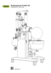
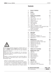
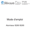
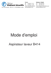
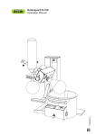
BÜCHI Rotavapor R-220
Table of Contents
Table of Contents
1
Scope of Delivery
2
2
Safety
3
3
Function
3.1 Principle of Operation
4
4.1
4.2
4.3
4.4
4.5
4.6
4.7
4.8
4.9
4.10
4.11
4.12
4.13
4.14
4.15
4.16
Putting into Operation
Installation Location
Unpacking
Setting up the Support Rod
Attachment of the EasyClamp
Removal of the EasyClamp
Installation of the Reflux Glass Assembly
Installation of the Descending Glass Assembly
Installation of the Descending Glass Assembly
with a 2nd Cooler
Installation of the Receiving Fixture
Attaching and Removing Flasks
Hose Coupling
Operating the Shut-off tap
Bath Replenishment (Optional)
Reset of the over-temperature protection
Heating Medium
Checking Installation
5
Operation
5.1 Arrangement of the Operator Control and
Display Elements
5.2 Adjusting the Maximum Set-Point Temperature
and Automatic Lowering of the Bath in Case of
a Power Interruption
5.3 Tips and Tricks
5.4 Table of Solvents
6
6
7
7
7
8
9
9
10
11
12
13
14
16
18
18
19
19
19
20
6
6.1
6.2
6.3
6.4
6.5
6.6
6.7
6.8
6.9
6.10
Maintenance
Taking Apart the Snap Flange Coupling
Assembling the Snap Flange Coupling
Removing the Evaporating Flask Seal
Inserting the Evaporating Flask Seal
Replacement of the Seals for the Distribution Head
Replacement of the Vacuum Seal
Cleaning
Vacuum Seal
Testing for Leaks
Customer Service
23
23
24
24
25
25
26
26
26
27
27
7
Taking out of Operation
28
8
8.1
8.2
8.3
8.4
Spare Parts and Accessories
Glass Assemblies D, D2, DB, DB2
Glass Assemblies R, RB, C
Miscellaneous
Accessories
9
9.1
9.2
9.3
9.4
9.5
Appendix
Technical Data
Materials Used
Error Messages
FCC requirements (for USA and Canada)
Declaration of Conformity
29
30/31
32/33
34
37
42
42
42
43
44
45
20
20
21
22
Read this Operating Manual through carefully before using
the Büchi Rotavapor R-220. Always keep these Instructions
readily available in the immediate vicinity of the unit so that
they make be consulted at any time.
Chapter 2 contains important safety rules which must be observed to ensure the safe operation of the rotary evaporator.
We reserve the right to make technical changes without
prior notification. No portion of this Operating Manual
may be reproduced, processed using electronic or optical
systems, duplicated, or distributed in any form without
the prior written approval of Büchi Labortechnik AG.
All rights reserved. © Büchi Labortechnik AG, 1999-2001
en, Version G (46 Pages)
R-220 Operation Manual
Ordering No.
96737
1
BÜCHI Rotavapor R-220
1 Scope of Delivery
1
Scope of Delivery
Component
1 Chassis, complete, with control and
driving unit and with heating bath
1 6L, 10L or 20L Evaporation flask
1 Receiving flask 1 x 10L Single receiver or
2 x 10L Interchangeable receivers
1 Glass assembly
(Refer to Chap. 4.6 - 4.8 for Figure)
Table 1: Scope of Supply
Standard Accessories:
1 Seal tool
Ordering No.
20057
1 Operating Manual
German
96736
English
96737
French
96738
Italian
96739
Spanish
96740
Table 2: Standard Accessories
Fig. 1: R-220, Overall View
2
BÜCHI Rotavapor R-220
2 Safety
2
Safety
This unit has been built in accordance with the latest state of
the art and with recognized rules of safety.
Nevertheless there are certain risks and dangers entailed with
this unit:
• whenever the unit is operated by individuals who lack
sufficient training;
• whenever the unit is used for some purpose other than its
authorized use.
2.1
Symbols
Stop
Information on dangers that can cause serious material
damage and severe personal injuries or death.
Warning
Information on dangers that can be injurious to one’s health
or cause material damage.
Note
Information pointing out technical requirements. A failure to
observe such information can lead to malfunctions, uneconomical operation, and losses in production.
2.2
Responsibilities of the Operator
This unit may only be used by technical staff and by individuals
who, based on their training or their professional experience,
have a good understanding of the dangers that can arise
from the its operation.
Staff who do not have this training and individuals who are
currently in training must be given careful instructions. This
Operating Manual should be used as the basis for such training.
2.3
Authorized Use
The rotary evaporator has been designed for use in technical
laboratories and in production. It is authorized for use in applications that work with the evaporation and condensation of
solvents.
It is used for:
• Evaporation of solvents and suspensions
• Drying of powders and granulates
• Re-crystallization
• Reactions under reflux
• Synthesis and Cleaning of refined chemicals
• Recycling and concentration of solvents
The authorized use of the Rotavapor also includes its care,
upkeep, and careful handling in accordance with the provisions
in this Operating Manual.
3
BÜCHI Rotavapor R-220
2 Safety
2.4
Unauthorized Use
Any use other than those indicated above, and any use that
is not in conformity with the Technical Data is considered to
be misuse. The operator himself bears sole responsibility for
all damage or injuries arising from any such use.
The following applications in particular are strictly forbidden:
• The production and processing of materials that can cause
spontaneous reactions, e.g., explosives;
• Working without the evaporation flask being immersed in
the water bath (risk of breakage);
• The drying of hard, brittle materials (e.g., stones, soil samples) that might cause damage to the receiving flask;
• Sudden shock-cooling of the evaporating flask.
The Rotavapor R-220 is not intended for work done under
overpressures.
2.5
Basic Dangers
Basic dangers arise when working with the following:
• The hot water or oil bath (risk of being scalded);
• Contaminated solvents that produce residues from distillation which could cause spontaneous reactions (e.g., metal
hydrides);
• Solvents that can produce peroxides (risk of explosions);
• Mixtures with unknown compositions or contamination;
• Damaged glassware;
• Electrostatic charges while working, e.g., during the transfer of combustible solutions and while drying powders;
• Temperatures of coolants that lie below the freezing point
of the distillate (A clogging of the distillate cooler due to
freezing out can result in too great an overpressure).
2.6
Safety Precautions
All regional and local laws and regulations must be observed.
The Rotavapor has been grounded internally to dissipate any
electrostatic charges on it.
4
BÜCHI Rotavapor R-220
2 Safety
It is always mandatory to wear personal protective gear such
as protective eyewear and protective clothing.
The machine must never be rotated without the snap flange
coupling and evaporation flask being closed.
No distillation may be started unless the evaporating flask is
immersed in the bath. There is always the risk that the neck
of the flask might break off due to the great weight involved.
There is a risk of becoming scalded while changing evaporating
flasks. Wearing gloves prevents this.
Check the glass components regularly for possible damage,
spreading impact marks, or cracks.
Never interrupt the grounding conductor (protective conductor).
Otherwise there will be the risk of an electrical shock!
The operator bears responsibility for providing proper instruction
of his operating staff. To aid him in doing this, translations of
this Operating Manual are also available in several other
languages. As an integral component of the rotary evaporator,
this Operating Manual must be readily available at all times to
the operating staff at the location where they are using the
unit.
The operator must inform the manufacturer immediately of
any and all events relevant to safety that occur in his use of
this equipment.
2.7
Modifications
No modifications are permissible without consulting with and
obtaining the written approval of the manufacturer.
No glass assemblies other than those recommended by the
manufacturer may be used, nor may any glass components
be put together arbitrarily.
Only those components of the rotary evaporator intended for
fulfillment of its function may be installed in or removed from
the unit. This may be done either by hand, or with the use of
the tool supplied along with the unit. The removal of safety
devices or covers using some commercially available tool is
— other than for authorized commissioning personnel — strictly
forbidden. Contact with parts that are electrically live may
result in fatal injury!
5
BÜCHI Rotavapor R-220
3 Function
3
Function
A vacuum rotary evaporator is used for quick single-stage
distillations that treat the product gently. The process is based
on the evaporation and condensation of solvents in a rotating
evaporating flask.
It is possible to work under a vacuum to ensure gentler treatment of the product and increase productive output.
Distillation may be done either under a vacuum or at atmospheric pressure.
A secure closeness is guaranteed in the low pressure range.
3.1
햶
햲 Evaporation Zone
The solvent in the evaporating flask is heated by the heating
bath. The rotation of the evaporating flask ensures an intensive exchange of heat and mass within the contents of
the flask, forming a thin film of solvent on the inner surface
of the flask. This combination of turbulence and film prevents
local overheating and ensures high distillation speed.
햳
햳 Rotary Drive
The drive unit ensure the uniform rotation of the evaporating
flask.
햴
햲
햵
Principle of Operation
햴 Cooling Zone
The solvent vapor flows into the cooler at a high speed.
This is where the energy in the solvent vapor is transferred
to the cooling medium (e.g., water). The solvent condenses.
햵 Receiving Flask
The receiving flask is used to collect the condensate.
햶 Vacuum Cover
The system pressure is reduced so as to lower the boiling
point of the solvent. The reduction in thermal loading that
results ensures gentle treatment of the product and offers
energetic advantages.
Fig. 2: Principle of operation of the R-220
The pressure (vacuum) of distillation, the temperature of the
heating bath, the rotational speed, and the size of the evaporating flask all affect the evaporation output. Refer to Chapter
5.3 for how to select the optimum conditions of distillation.
6
BÜCHI Rotavapor R-220
4 Putting into Operation
4
Putting into Operation
The danger zone around the Rotavapor R-220 can extend
outward by up to 10 m. When working inside this danger
zone, there is a risk of damaging the glass parts, which could
cause them to implode.
The electrical connection must be installed and checked
by an authorized person.
4.1
Installation Location
Always set the unit up on a clean, stable, and flat surface.
Never at a location where there is a great deal of personal
traffic (breaking or broken glass) !
The dimensions of the rotary evaporator are:
Height:
without trolley
with trolley
Reflux
Descending
Bullfrog Reflux
Bullfrog Descending
1700 mm
1800 mm
1430 mm
1550 mm
Reflux
Descending
2300 mm
2400 mm
Width:
Reflux
1100 mm
Descending
1250 mm
Descending, with 2 coolers 1250 mm
Depth:
Single receiver
Interchangeable receivers
4.2
550 mm
650 mm
Unpacking
Take care not to break the glass when opening cartons that
contain glassware.
Look for any damage after unpacking. It is important that any
damage in transit be identified right when unpacking. If necessary, make an immediate assessment of the situation (Notify
the post office, the railroad, or the shipping company involved).
Save the original packing for possible transport at a later date.
7
BÜCHI Rotavapor R-220
4 Putting into Operation
4.3
Setting up the Support Rod
• Place the support rod 햳 into the holder provided for it and
lower it into the foot hole at the back. Fix it tight using the
locking screw 햲.
• Put the positioning ring 햴 on over the rod, 150 mm below
the upper edge.
햵
• Lay the pivoting clamp 햵 on top of the positioning ring.
햴
• Attach the pivoting clamp for the receiving flask 200 mm
above the bottom edge of the rod.
햳
햲
When installing an interchangeable receiver:
• Place the short support rod into the holder at the front and
lower it into the foot hole. Screw it tight using the locking
screw.
• Attach the pivoting clamp approx. 200 mm above the lower
edge of the rod.
Fig. 3: Support rod
8
BÜCHI Rotavapor R-220
4 Putting into Operation
4.4
Attachment of the EasyClamp
• Carefully lay the EasyClamp around the glass and fold the
top and bottom segments together, closing them at their
open connection point.
• Insert the bolt that does not have a spacer spring, and
tighten the knurled nuts slightly.
• Tighten all knurled nuts uniformly by hand.
Note:
Always tighten the knurled nuts by hand and not to the block
(with the spring pressed together completely). Otherwise the
prestressing will be lost.
There must always be a gap of about 2 mm between the
knurled nut and the support surface.
Fig. 4: Attachment of the EasyClamp
4.5
Removal of the EasyClamp
On all EasyClamp connections, only the bolt without a
spacer spring has to be removed in order to open the connection.
• Release the knurled nuts on all (2 or 3) bolts until the springs
have been relieved. Do not, however, screw the nut all
the way off.
• On the bolt that does not have a spacer spring, release
the knurled nut far enough (without removing it completely)
so that the bolt can be tilted out and removed as a unit.
• At the connection point, which is now open, spread the
top and bottom segments apart and carefully remove the
EasyClamp.
Fig. 5: Removal of the EasyClamp
9
BÜCHI Rotavapor R-220
4 Putting into Operation
4.6
Installation of the Reflux Glass Assembly
All glassware used must be intact, with no signs of cracks,
spreading impact marks, or other damage. Inspect the glassware visually before installing it.
• Fix the reflux distribution head 햲 in position on the gear
head using a DN70 EasyClamp connection.
햶
• Introduce the cooler 햳, together with the cooler holder
햴, into the pivoting clamp 햵 and connect it to the distribution head (DN45 EasyClamp connection).
• Align the cooler 햳 in a vertical position and fix it in place
with the pivoting clamp 햵.
햴
• Screw the cooling water hose nipples 햶 onto the cooler
햳.
• Insert the shut-off tap 햷 into the distribution head 햲 and
tighten it firmly.
햵
• Introduce the stop cock 햸 into the distribution head with
the PTFE hose attached to it, and secure it with a standard
joint clamp 햹.
햳
햶
햷
햹
햸
햲
햺
Fig. 6: Reflux glass assembly
10
햻
• Attach the condensate cooler 햺 to the distributor head
with a DN25 EasyClamp connection and fix it in position.
• Screw the temperature sensor 햻 into the distribution head
햲.
• Check all EasyClamp connections and tighten them evenly
and in parallel.
→ The installation of the receiving fixture is described on Page
13.
BÜCHI Rotavapor R-220
4 Putting into Operation
4.7 Installation of the Descending Glass Assembly
All glassware used must be intact, with no signs of cracks,
spreading impact marks, or other damage. Inspect the glassware visually before installing it.
• Fix the descending distributor head 햲 in position on the
gear head using a DN70 EasyClamp connection.
햾
햷
햸
• Put the expansion vessel 햳 onto the distribution head
and fix it in position with a DN45 EasyClamp connection.
• Introduce the cooler 햴, together with the cooler holder
햵, into the pivoting clamp 햶 and connect it to the distribution head (DN45 EasyClamp connection).
• Connect to the cooler and the expansion vessel using the
U-tube 햷 and fix in position with two DN45 EasyClamp
connections.
햴
• Align the cooler 햴 and the expansion vessel 햳 in their
vertical positions and fix them in place with a pivoting clamp
햶.
햷
햶
햳
• Screw the cooling water hose nipples 햸 onto the cooler
햴.
• Insert the stop cock 햹, with the PTFE hose mounted on
it, into the distribution head, and secure it with a standard
joint clamp 햺.
햸
• Fasten the vacuum connector 햻 to the Y-connection 햽
with a DN45 EasyClamp connection and fix the unit in
place on the lower end of the cooler with a DN45
EasyClamp.
햻
햲
햽
햺햹
Fig. 7: Downgrade glass assembly
• Screw the temperature sensor 햾 into the support connection in the U-tube 햷.
• Check all EasyClamp connections and tighten them evenly
and in parallel.
→ The installation of the receiving fixture is described on Page
13.
11
BÜCHI Rotavapor R-220
4 Putting into Operation
4.8
Installation of the Descending Glass Assembly
with a 2nd Cooler
All glassware used must be intact, with no signs of cracks,
spreading impact marks, or other damage. Inspect the glassware visually before installing it.
• Fix the descending distributor head 햲 in position on the
gear head using a DN70 EasyClamp connection.
헀
햷
햴
• Place the expansion vessel 햳 on the distribution head
and fix it in position with a DN45 EasyClamp connection.
• Introduce the cooler 햴, together with the cooler holder
햵, into the pivoting clamp 햶.
햽
• Connect the cooler and the expansion vessel with the Utube 햷 and fix them in position with two DN45 EasyClamp
connections.
햺
햹
• Insert the second cooler 햸, together with the cooler holder
햹, into the pivoting clamp 햺.
햶
햵
햸
햳
햲
햽
• Join the two coolers with the Y-connection 햻 and fix them
in position with two DN45 EasyClamp connections.
• Align the coolers (햴 and 햸) and the expansion vessel 햳
in their vertical positions and fix them in place with pivoting
clamps (햶 and 햺).
• Screw the cooling water hose nipples 햽 onto coolers 햴
and 햸.
• Insert the stop cock 햾, with the PTFE hose mounted on
it, into the distribution head, and secure it with a standard
joint clamp 햿.
햻
햿 햾
Fig. 8: Downgrade glass assembly with two coolers
• Screw the temperature sensor 헀 into the support connection in the U-tube.
• Check all EasyClamp connections and tighten them evenly
and in parallel.
→ The installation of the receiving fixture is described on Page
13.
12
BÜCHI Rotavapor R-220
4 Putting into Operation
4.9
Installation of the Receiving Fixture
All glassware used must be intact, with no signs of cracks,
spreading impact marks, or other damage. Inspect the glassware visually before installing it.
Single Receiver
햷
햶
햵
햲
햴
햳
Fig. 9: Single receiver, reflux
• Fasten the support ring 햲 to the support rod with a pivoting
clamp 햳.
• Screw the outlet valves 햴 on the receiving flask 햵 on
tight using a DN25 EasyClamp connection.
• Place the receiving flask on the support ring 햲.
With a reflux glass assembly:
• Bring the support up and fix the flask in position on the distillate cooler using a DN25 EasyClamp connection.
햵
햲
햴
햳
Fig.10: Single receiver, downgrade
With a descending glass assembly:
• Attach the branching piece 햶 to the opening at the bottom
of the Y-connection with a DN45 EasyClamp connection.
• Insert the shut-off tap 햷 into the branching piece 햶 and
tighten it firmly.
• Bring the support up and fix the receiving flask 햵 in position
on the branching piece 햶 using a DN25 EasyClamp connection.
Dual Receiver
• Fasten the support rings 햲 to the support rods at the
front and back using pivoting clamps 햳.
• Screw the outlet valves 햴 firmly onto the receiving flask
햵 using DN25 EasyClamp connections.
• Place the receiving flasks 햵 on the support rings 햲.
• Screw the two shut-off taps 햶 into the branching pieces
(햷 and 햸) and tighten them.
• Connect the branching pieces with a DN25 EasyClamp
connection. Place them on the receiving flasks 햵, and
fasten them with DN25 EasyClamp connections.
햶
햶
햸
햷
햵
햲
햲
햳
햴
햳
햴
With a reflux glass assembly:
• Bring the receiving flask up, and fasten the branching piece
햸 to the condensate cooler using a DN25 EasyClamp
connection.
With a descending glass assembly:
• Bring the receiving flask up, and fasten the branching piece
햸 to the Y-connection using a DN25 EasyClamp connection.
Fig. 11: Interchangeable receiver
13
BÜCHI Rotavapor R-220
4 Putting into Operation
4.10 Attaching and Removing Flasks
Bring up the flask
• With the snap flange coupling open, lay the flask in position.
• Close the first segment of the snap flange coupling( T h e
hook must latch in).
Fig. 12: Snap flange coupling, with flask laid in place
• Close the second segment of the snap flange coupling.
• Insert the closure hook and press down the closure lever.
A clear resistance must be felt when this is done. If not,
readjust the tension on the closure.
Fig. 13: Closing the snap flange coupling
Adjusting the tension on the closure:
Open the closure hook up, and turn it.
Turning clockwise
Turning counterclockwise
increases pressure
reduces pressure
If the flange of the evaporating flask is outside of a certain
tolerance, the adjustment with the hook is not possible.
This evaporating flask must not be used!
Fig. 14: Adjusting the tension on the closure
14
BÜCHI Rotavapor R-220
4 Putting into Operation
Removing flasks
• Place your hand under the flask to hold it from below.
• Open the closure lever 햲.
햲
• Use your thumb to release the closure hook 햳.
• Flip up the first segment of the snap flange coupling.
햳
Fig. 15: Opening the closure
햴
• With your hand under the flask, lift it lightly slightly from
below and relieve pressure on it.
• Press the hook 햴 in.
• Open the second segment of the snap flange coupling.
• Lift the flask out at the top and remove it.
Fig. 16: Opening the second segment
15
4 Putting into Operation
BÜCHI Rotavapor R-220
4.11 Hose Couplings
In general, observe the following items for all glass assemblies.
The cooling water inlet is always at the lower condenser
connection.
When there are two condensers (D2 und DB2), the two condensers can be connected serially, the additional condenser
being cooled first.
햳
The following is the key for all of the hose diagrams on these
two pages.
햲
햳
햴
햵
햶
햷
햸
햲
햶
햷
햳
햵
햴
햲
Fig. 17: Hose Couplings 1
16
Cooling water inlet for first condenser
Cooling water outlet for first condenser
Cooling water inlet for second condenser
Cooling water outlet for second condenser
Vacuum connection
Vacuum controller
T-piece (026117)
BÜCHI Rotavapor R-220
4 Putting into Operation
The following is the key for all of the hose diagrams on these
two pages.
햵
햷
햵
햶
햲
햳
햴
햵
햶
햷
햸
Cooling water inlet for first condenser
Cooling water outlet for first condenser
Cooling water inlet for second condenser
Cooling water outlet for second condenser
Vacuum connection
Vacuum controller
T-piece (026117)
햴
햳
햲
햷
햷
햸
햶
햳
햲
Fig. 18: Hose Couplings 2
17
BÜCHI Rotavapor R-220
4 Putting into Operation
4.12 Operating the Shut-off tap
The shut-off tap is of a special design. It does not have a
continuous thread on its inside for tightening it, but rather a
sliding plane with two fixed latching positions. The closing pressure when it is in a closed position is provided by a prestressed
spring.
햳
햲
• Insert the shut-off tap on the distribution head and turn
the white lower section of the grip 햲 clockwise until the
shut-off tap is tightly seated.
• To open:
Turn the gray upper section of the grip 햳 clockwise until
the shut-off tap latches into the 1st position.
If the opening is not large enough, continue turning until
the shut-off tap reaches the 2nd position.
햳
Fig. 19: Shut-off tap
4.13 Bath Replenishment (Optional)
햴
햲 Bath replenishment inlet
Hose nipple, Diam.14 mm
햳 Bath replenishment outlet
Hose nipple, Diam.14 mm
Fig. 20: Bath replenishment
햲
Opening the needle valve 햴 slightly by one-quarter turn produces a continuous supply flow.
햳
Introduce the Open/Shut valve supplied with the unit into the
bath replenishment inlet 햲 and connect it to “CW Valve” on
the back wall of the unit. This interrupts the replenishment of
the bath when rotation stops.
The installation of the water valve is described in chapter
8, Replacement Parts, Water Valve.
If oil is used as heating medium, the bath replenishment
has to be emptied and disconnected from the water inlet.
Otherwise, there is a risk of water pouring into the hot oil
bath.
Operating Instructions!
When rotation stops, the cooling water and bath replenishment
water switch OFF after short delay. As soon as rotation starts,
the valve reopens and the water flows once again.
Fig. 21: Bath replenishment
18
BÜCHI Rotavapor R-220
4 Putting into Operation
4.14 Reset of the over-temperature protection
If the heater heats up over 205°C (e.g. if no heating medium
is in the bath), it is cut off by a mechanical overtemperature
protection.The overtemperature protection is reset by pushing
the button under the heating block.
Fig. 22: Reset of the over-temperature protection
4.15 Heating Medium
Never operate the heating bath when there is no heating medium in it!
Suitable heating media include:
• Water (some Borax should be added when using
deionized water)
• Heat transfer oils suitable for use at temperatures up to
160° C (e.g., Ucon HTF 14, Fluka AG).
• Water-soluble polyethylene glycol
(e.g., Polyethylene glycol 600, Fluka AG).
After the oil bath has been standing opened for a prolonged
period, condensation water can collect on the bottom. When
the bath is used again, it must be heated above 100°C with
rotating flask in order to drive the water out.
4.16 Checking Installation
After installation has been completed and before doing the
first distillation, check to make sure the installation has been
carried out correctly:
• Inspect the glass visually for possible damage.
• Check that all connections (steam, water, vacuum) have
been fixed properly in position.
• Check the tightness of the vacuum.
19
BÜCHI Rotavapor R-220
5 Operation
5
Operation
Make certain that the unit has been commissioned properly
as described in Chapter 4.
5.1
Arrangement of the Operator Control and
Display Elements
햲 Main breaker switch
햳 Lift for the bath
햻
햴 Rotation ON/OFF
햺
햵 Rotating speed adjustment
햶
햶 Rotating speed display
햹
햷 Heater ON/OFF
햸 Input: Set-point temperature for bath
햵
햸
햹 Temperature UP/DOWN
햺 Display for bath temperature
햷
햴
햻 Display for vapour temperature
햽 Aeration
햽
햳
햲
The bath is lowered automatically when the unit is switched
off or in case of a power failure to ensure that the evaporating
flask will in all cases remain outside the source of heat (optional).
Fig. 23: Operator control elements for the R-220
5.2
Adjusting the Maximum Set-Point
Temperature and Automatic Lowering of
the Bath in Case of a Power Interruption
Setting the Maximum Set-Point Temperature
• Press the button “SET TEMP” 햸, simultaneously switching
on the main breaker switch 햲. This activates the input for
setting the maximum set-point temperature.
• The value can be set at any level desired by pressing the
“DOWN” and “UP” buttons 햹.
• The input is stored and the unit switched into the operating
mode only after the “AERATE” button 햽 is then pressed.
20
BÜCHI Rotavapor R-220
5 Operation
Adjusting the Optional Automatic Lowering of the
Bath in Case of a Power Interruption
• Press the button “LIFT down” 햳, simultaneously switching
on the main breaker switch 햲.
This results in the display “ON” or “OFF”.
On = The lift lowering has been switched ON
Off = The lift lowering has not been switched ON.
• To switch back and forth between ON and OFF, press
repeatedly on the button “LIFT down” 햳.
• The input is stored and the unit switched into the operating
mode only after the “AERATE” button 햽 is then pressed
repeatedly.
5.3
Tips and Tricks
Selection of the Distillation Temperature
In order to attain optimum distillation conditions, the energy
supplied to the distillation from the bath must be dissipated
again across the cooler. In order to ensure this, it is best to
work according to the following rule of thumb:
Cooling water
max. 20 ºC
∆T2 Boiling temperature
40 ºC
∆T1 Bath
60 ºC
How do you attain these conditions?
• Set the bath temperature at 60 ºC.
• Adjust the cooling water. Its temperature should not be
higher than 20 ºC.
• Allow the cooling water to flow through the cooler at a rate
of about 120–150 liters/hr.
• Select the working vacuum so that the boiling point of the
solvent is at 40 ºC.
• Obtain the corresponding value for the vacuum from the
Table of solvents.
Advantages of a Bath Temperature of 60 °C
• Evaporating flasks can be changed without any danger of
scalding.
• The rate of water evaporation out of the heating bath is
not yet very high.
• The energy in the heating bath is being utilized very efficiently.
The solvent should condense out in approx. 2/3 to 3/4 of the
lengths of the cooling coils present.
21
BÜCHI Rotavapor R-220
5 Operation
5.4
Solvent
Formula Molar Mass
in g/mol
Evaporation
Energy in J/g
Table of Solvents
Boiling Point Spec.Gravity
at 1013 mbar
in g/cm3
Vacuum in mbar for a
Boiling Point at 40°C
Acetic acid
C2H4O2
60.0
695
118
1.049
44
Acetone
C3 H6 O
58.1
553
56
0.790
556
n-Amyl alcohol, n-Pentanol
C5H12O
88.1
595
37
0.814
11
Benzene
C6H6
78.1
548
80
0.877
236
n-Butanol, tert. Butanol
C4H10O
74.1
620
118
0.810
25
(2-Methyl-2-Propanol)
C4H10O
74.1
590
82
0.789
130
Carbon tetrachloride
CCI4
153.8
226
77
1.594
271
Chlorobenzene
C6H5CI
112.6
377
132
1.106
36
Chloroform
CHCI3
119.4
264
62
1.483
474
Cyclohexane
C6H12
84.0
389
81
0.779
235
Diethyl ether
C4H10O
74.0
389
35
0.714
850
1,2,-Dichlorethane
C2H4CI2
99.0
335
84
1.235
210
1,2,-Dichlorethylene (cis)
C2H2CI2
97.0
322
60
1.284
479
1,2,-Dichlorethylene (trans)
C2H2CI2
97.0
314
48
1.257
751
Diisopropyl ether
C6H14O
102.0
318
68
0.724
375
Dioxane
C4H8O2
88.1
406
101
1.034
107
DMF (Dimethylformamide)
C3H7NO
73.1
153
0.949
11
Ethanol
C2 H6 O
46.0
879
79
0.789
175
Ethyl acetate
C4H8O2
88.1
394
77
0.900
240
Heptane
C7H16
100.2
373
98
0.684
120
Hexane
C6H14
86.2
368
69
0.660
335
Isoamyl alcohol, 3-Methyl-1-Butanol
C5H12O
88.1
595
129
0.809
14
Isopropyl alcohol
C 3 H8 O
60.1
699
82
0.786
137
Methanol
CH 4O
32.0
1227
65
0.791
337
Methylene chloride, Dichloromethane CH2CI2
84.9
373
40
1.327
850
Methylethylketon
C4 H 8 O
72.1
473
80
0.805
243
Pentachlorethane
C2HCI5
202.3
201
162
1.680
13
Pentane
C5H12
72.1
381
36
0.626
850
n-Propyl alcohol
C3 H8 O
60.1
787
97
0.804
67
1,1,2,2,-Tetrachloroethane
C2H2CI4
167.9
247
146
1.595
35
Tetrachloroethylene
C2CI4
165.8
234
121
1.623
53
THF (Tetrahydrofurane)
C4 H 8 O
72.1
67
0.889
357
Toluol
C7H8
92.2
427
111
0.867
77
1,1,1,-Trichlorethane
C2H3CI3
133.4
251
74
1.339
300
Trichlorethylene
C2HCI3
131.3
264
87
1.464
183
100
1.000
Water
H2 O
18.0
2261
Xylol (Mixture)
C8H10
106.2
389
(o)
144
0.880
(m)
139
0.864
(p)
138
0.861
Table 3: Table of Solvents (CRC Handbook, 65th Ed)
22
72
25
BÜCHI Rotavapor R-220
6 Maintenance
6
Maintenance
Please note all rules aimed at keeping the rotary evaporator
in a functional condition. These also include periodic cleaning
and inspection for any damage that might have occurred.
Make certain that supply of power to the unit has been interrupted before doing any maintenance work on the unit. Always
support the bath from below, on the underside of the bath
whenever doing any repair work.
6.1
Taking Apart the Snap Flange Coupling
• Close the two segments of the snap flange coupling.
• Turn the snap flange coupling by 180°, until the closure
faces down.
• Have Tool No. 20075 ready at hand.
• Reopen the closure.
• Lift the 1st segment of the snap flange coupling to open it.
• Lift the 2nd segment of the snap flange coupling to open it.
• With three fingers at the tip, reach under the middle segment and raise it up.
• Insert Tool No. 20075 in at the side, between the lugs on
the positional lock. Turn lightly until the pin becomes unlatched. Take the snap flange coupling assembly off.
Fig. 24: Snap flange coupling, closed
• Clean the snap flange coupling.
23
BÜCHI Rotavapor R-220
6 Maintenance
6.2
Assembling the Snap Flange Coupling
• Insert the snap flange coupling from above, until the pins
in the lock latch into the hole on the lug.
• Close the two segments of the snap flange coupling.
• Turn the snap flange coupling again by 180°, until the closure
lies at the top.
• Lift the two segments of the snap flange coupling to open
them.
• Lay the neck of the glass flask into the middle segment
and raise the flask slightly.
• Pull the segment on the left back slightly and close it until
the hook latches in place.
• Close the segment on the right.
Fig. 25: Assembling the snap flange coupling
• Insert the closure hook and close the snap flange coupling
with the closure lever. A clear resistance must be felt when
doing this. Otherwise no seal can be fully guaranteed.
6.3
Removing the Evaporating Flask Seal
• Seal the holder for the seal by 180°, until the opening faces
up.
• Take hold of the seal with both hands, from above and
from the front, and pull it out slowly.
• Tilt the seal slightly and carefully pull it all the way out. Be
careful not to damage the glass centering bulge when
doing so.
• Remove the vapor duct.
Fig. 26: Removing the evaporating flask seal
24
BÜCHI Rotavapor R-220
6 Maintenance
6.4
Inserting the Evaporating Flask Seal
• Insert the vapor duct.
• Insert the seal. Using gentle pressure, shove it across the
lock preventing it from twisting out of position, and then
shove it all the way in. Press it with both thumbs until it
latches in position.
햲
• The knob 햲 in the gearhead must come to rest in the
notch 햳 in the vapour duct.
햳
Fig. 27: Inserting the evaporating flask seal 1
햲
햳
Fig. 28: Inserting the evaporating flask seal 2
6.5
Replacement of the Seals for the Distribution
Head
• Open the DN70 EasyClamp by releasing the knurled nuts
on all 3 bolts, but do not screw the nuts completely off.
• Tilt the top bolt out toward the back.
햲
• Open the upper and lower EasyClamp segments and
carefully lift the distribution head off the glass assembly.
• Take out the seal 햲 laid in at the front and replace it.
Fig. 29: Replacement of the seals for the distribution head
25
BÜCHI Rotavapor R-220
6 Maintenance
6.6
Replacement of the Vacuum Seal
• Remove the DN70 EasyClamp completely and take off
the distribution head.
• Pull the cylindrical seal holder out and turn it over.
• Insert Tool No. 20075 into the metal guide on the seal and
pull the seal out.
• Put in the new seal with the dark scraper ring facing the
inside and the metal guide ring facing outward.
• Insert the cylinder with the seal at the back lying on the inside.
• Insert the seal at the front.
• Provisionally install the EasyClamp using 2 bolts.
• Set the distribution head of the glass assembly on top of
the seal.
• Close the segments of the EasyClamp. Flip the top bolt up
and in, and hand-tighten all 3 knurled nuts.
Fig. 30: Replacement of the Vacuum Seal 1
Tip:
When the glass assembly "R" is in place, the vacuum seal
can be taken out and/or cleaned without the glass assembly
having to be removed.
• Remove the complete DN70 EasyClamp assembly from
the distribution head.
• Using a socket wrench, release the fastening for the support rod.
• Carefully turn the glass assembly out around the support
rod as an axis.
• Remove the seal.
Fig. 31: Replacement of the Vacuum Seal 2
6.7
Cleaning
Use commercially available cleaning agents to clean the glassware.
Merely wipe the housing off with a damp cloth (without using
any organic solvents).
Use a commercially available de-liming agent to dissolve residues of lime in the bath and flush the bath out well.
26
BÜCHI Rotavapor R-220
6 Maintenance
6.8
Vacuum Seal
The seal should be cleaned whenever necessary, but at least
once every six months.
During the intake phase, which lasts approx. 10 hours, the
seal will show signs of greater material loss due to wear. This
is normal for a PTFE seal.
Cleaning
Before the packet of seals can be removed, the distribution
head must be released and screwed off. The complete seal
packet can then be taken out and cleaned.
Wipe off the sealing lip using a soft, dry cloth. Clean the running
surface on the vapor duct well.
Regular cleaning of the seal will result in a longer service life
for it.
6.9
Testing for Leaks
After the rotary evaporator has been completely assembled
and before putting it into operation, i.e., while it is clean and
dry, check for tightness of the vacuum. To do this, evacuate
the unit to below 100 mbar and then close the vacuum line.
The rate of pressure rise must not exceed 3 to 5 mbar per 15
minutes.
A greater pressure rise indicates a leak in the vacuum seal. In
such a case, recheck all EasyClamp connections and all valves.
6.10 Customer Service
No intervention on or in the unit is permissible except when
done by authorized Service personnel. These are individuals
with a well-backed technical professional training and
knowledge of the dangers that result from a failure to observe
the safety precautions required. BÜCHI’s Customer Service
representatives have available to them a Service Manual
specific to the unit in question. That manual is issued only to
authorized Service personnel.
The addresses of BÜCHI’s official Customer Service representatives are shown on the back cover of this Operation Manual.
Please turn to these representatives should you have any
malfunctions, technical questions, or problems in using the unit.
BÜCHI’s Customer Service Dept. will be ready and happy to
offer the following services:
•
•
•
•
Spare parts service
Repair service
Maintenance service
Technical consultation.
27
BÜCHI Rotavapor R-220
7 Taking out of Operation
7
Taking out of Operation
Remove all hazardous materials and clean the unit thoroughly.
This prevents any risk that individuals could suffer injuries due
to contact with hazardous materials.
7.1
Storage
Always store the unit and spare parts for it in a clean and dry
location.
7.2
Packing / Transport
The original packing has been specially designed for transporting the unit and the glass parts for it. Use only the original
packing materials for any further transport.
7.3
Waste Disposal
Table 7 in the Appendix, Chapter 9, contains a list of the materials, including their material codes, used for the most important
components of the unit. This list has been provided in order to
enable environmentally correct disposal of the rotary evaporator. It ensures that the parts can be separated and sent for
appropriate recycling. Please refer to the pertinent guidelines
when disposing of electrical parts. In addition, observe all
regional and local laws covering waste disposal.
Used batteries may be returned directly to your BÜCHI representative for disposal.
28
BÜCHI Rotavapor R-220
8 Spare Parts and Accessories
8
Spare Parts and Accessories
Only original BÜCHI accessories and spare parts ensure safe
operation and a proper functioning of the unit. The use of
spare parts and accessories other than those from BÜCHI is
permissible only with prior approval of the manufacturer. The
Spare Parts Catalog may be used for purposes of assembly
and disassembly only in conjunction with the corresponding
Chapters 4 and 7 in this Operation Manual. Dis-closure and
distribution to third parties, and manufacturing based on this
manual are strictly forbidden.
Copyright by Büchi AG. All rights reserved.
29
BÜCHI Rotavapor R-220
8 Spare Parts and Accessories
D
D2
27150
27150
27289
41076
27289
41076
27308
41131
27308
1165
41131
41155
41155
1165
41151 / 41156
41159
1129
41335
41335
3577/5155
27338
27277/
41164
1169
41130
41348
41130
DB
27277/
41164
1169
41348
DB2
41076
27837
27837
41076
41120
1165
1165
41120
27825
27824
27825
41335
41335
27277/
41354
1169
41348
41348
Fig. 32: Spare parts, Glass Assemblies D, D2, DB, DB2
30
27277/
41354
41166
BÜCHI Rotavapor R-220
8 Spare Parts and Accessories
8.1 Spare Parts: Glass Assemblies D, D2, DB, DB2
Component
41151
41155
41120 (Bullfrog)
41156
41241 (DN40)
Ordering No.
Vacuum connector PLG
01129
Expansion vessel PLG
01165
Y-connection PLG
01169
Threaded sleeve Svl 22
03577
Seal Svl 22 Id 17 PTFE
05155
U-tube PLG
27150
PTFE hose, Outer Diam. 10.0x1.0
27277
Screwed fitting Svl 22
27289
Cooler, 3 coil PLG
27308
Hose nipple
27338
Cooler Bullfrog, closed, PLG
27824
Cooler Bullfrog PLG
27825
U-Tube Bullfrog PLG
27837
Temperature sensor B, complete
41076
Glass holder B, complete
41120
EasyClamp, DN25
41130
EasyClamp, DN40
41131
Pivoting clamp, complete
41151
Glass holder, complete
41155
Clamping lever
41156
Cooler, 3-coil, closed PLG
41159
Y-connection Bullfrog PLG
41166
Set of bolts for EasyClamp, DN25
41240
Set of bolts for EasyClamp, DN40
41241
Inlet valve, complete
41348
Connection PTFE
41354
Distribution piece “D” PLG
41335
Table 4: Spare parts, Glass Assemblies D, D2, DB, DB2
41240 (DN25)
31
BÜCHI Rotavapor R-220
8 Spare Parts and Accessories
R
RB
3577
5155
27338
41159
27289
41167
41151/
41156
27824
41120
41155
27289
41348
41060
41348
41373
41076
41228
41373
41228
41162
41162
27277 /
41164
27289
C
25979 /
25981
3577
5155
27338
25124
25978
41079
41060
41348
41076
41373
41228
41162
27277/
41164
Fig.33: Spare parts, Glass Assemblies R, RB, C
32
27277 /
41164
BÜCHI Rotavapor R-220
8 Spare Parts and Accessories
8.2
Spare Parts: Glass Assemblies R, RB, C
Component
41151
41155
41120 (Bullfrog)
41079 (Cold trap)
41156
41241 (DN40)
41240 (DN25)
Ordering No.
Threaded sleeve Svl 22
03577
Seal Svl 22 Id 17 PTFE
05155
Cold trap
25124
Cold trap, PLG
25978
Cold trap cover
25979
Cover seal
25981
PTFE hose, Outer Diam. 10.0x1.0
27277
Screwed fitting Svl 22
27289
Hose nipple
27338
Cooler Bullfrog, closed, PLG
27824
Shut-off tap, large, complete
41060
Temperature sensor B, complete
41076
Glass holder C, complete
41079
Glass holder B, complete
41120
EasyClamp, DN25
41130
EasyClamp, DN40
41131
Pivoting clamp, complete
41151
Glass holder, complete
41155
Clamping lever
41156
Cooler, 3-coil, closed PLG
41159
Condensate cooler
41162
Cold trap, complete
41167
Set of 10 teflon discs
41228
Set of bolts for EasyClamp, DN25
41240
Set of bolts for EasyClamp, DN40
41241
Inlet valve, complete
41348
Connection, PTFE
41354
Distribution piece "R"
41373
Table 5: Spare parts, Glass Assemblies R, RB, C
33
BÜCHI Rotavapor R-220
8 Spare Parts and Accessories
8.3
Miscellaneous
Component
Ordering No.
Interchangeable receiver (W)
41062
41049
41048
28582
37569
Receiving flask 10L
37569
Branching piece 1 PLG
41048
Branching piece 2 PLG
41049
Outlet valve, DN25/2
41061
Shut-off tap, small, complete
41062
EasyClamp, DN25
41130
Pivoting clamp, complete
41151
Base for flask
41252
Ventilation cap
28582
41252
41151
41061
Fig. 34: Interchangeable receiver (W)
Single receiver (E)
41062
41053
41130
28582
37569
Receiving flask 10L
37569
Branching piece PLG
41053
Outlet valve, DN25/2
41061
Shut-off tap, small, complete
41062
EasyClamp, DN25
41130
Pivoting clamp, complete
41151
Base for flask
41252
Ventilation cap
28582
41252
41151
41061
Fig. 35: Single receiver (E)
Hose Connections
34
Softaflex hose, Inside Diam. 8.0 (3.4 m)
04113
Vacuum hose, Inside Diam. 10.0x5.0 (3.5 m)
04125
Plastic hose, Inside Diam. 10.0x2.0 (4.5 m)
27146
PTFE hose, Outside Diam.10.0x1.0 (2.0 m)
27277
BÜCHI Rotavapor R-220
8 Spare Parts and Accessories
41094
41095
41230
41121
41084
27378
41231
20075
41135
41229
Fig. 36: Sealing elements
Component
Ordering No.
Sealing elements
41346
41354
03223
00398
41147
Seal SVL 30
00398
Screw Cap SVL 30
03223
Screw Cap SVL 15
03549
Seal tool
20075
O-ring 130x5.0 Fpm70
27378
Vapor duct
41084
41946
Seal holder
41094
03549
Vacuum seal
41095
Evaporating flask seal, complete
41121
Easy Clamp element, DN70
41135
Set of 5 O-rings 64x5.0
41229
Set of 10 cover caps, D11 Pa
41230
Set of distribution head sealings
41231
Glass body
41346
Inlet valve, complete
41348
Connection, PTFE
41354
PTFE bellow
41388
Set of 5 SVL 15 seals
41946
41147
Fig. 37: Inlet valve, complete
Support ring inlet valve
35
BÜCHI Rotavapor R-220
8 Spare Parts and Accessories
Component
Ordering No.
Adjustable machine leg
41018
Clip
41110
Detent
41111
Snap flange coupling, completel.
41112
Protective screen
41214
Fig. 38: Machine leg
41111
41110
41112
Fig. 39: Snap flange coupling, complete
Fig. 40: Protective screen
36
BÜCHI Rotavapor R-220
8 Spare Parts and Accessories
8.4
Accessories
햳
Component
햲
Lamella curtain
Ordering No.
Lamella curtain
41256
Individual lamella
41267
Installation Instructions!
1) Put the lamella curtain 햲 on the support rod 햳.
2) Turn the lamella curtain until position is parallel to the edge
of the chassis.
3) Tighten the screw.
Fig. 41: Lamella curtain
Foam detector
The foam detection consists of a special distribution piece for
the descending glass configuration, the sensor, power supply
and the aeration valve. The system will detect the rising foam
and aerate the system for a split second.
Foam detector
40507
Fig. 42: Foam detector
37
BÜCHI Rotavapor R-220
8 Spare Parts and Accessories
Component
Ordering No.
6 L Evaporating flask
27470
10 L Evaporating flask
27469
20 L Evaporating flask
27468
Fig. 43: Evaporating flask
This special flask is particularly suited for drying powdery substances or a homogeneous mixture of solid products. The
baffles attached on the circumference of the flask ensure an
intensive circulation of the contents inside the flask.
Fig. 44: Drying flask
38
10 L Drying flask
28592
20 L Drying flask
28593
BÜCHI Rotavapor R-220
8 Spare Parts and Accessories
Component
Ordering No.
Splash Protection
햳
Splash Protection
41201
Protective shield
41204
Protective shield seal
41259
Installation Instructions!
1) Switch the unit OFF.
2) Remove the two bolts 햲 and the plastic cover 햳.
3) Put on the seal 햵.
4) Plug in the plug 햴.
햲
5) Fasten the splash protection in place with the bolts 햶.
6) Switch the unit ON.
Operating Instructions!
햵
햴
Opening the splash protection switches the rotation OFF. When
the splash protection is closed again, the flask starts to rotate
once more when the rotation button is pressed.
햶
Fig. 45: Splash Protection
39
BÜCHI Rotavapor R-220
8 Spare Parts and Accessories
Component
Ordering No.
Water Valve
햲
Water valve cpl.
41191
T-piece
26835
Installation Instructions!
1) Switch the unit OFF.
햷
2) Connect the water valve 햲 to the water cock.
햸
With optional bath replenishment
햵
3) Connect the water hose 햳 to the tee 햴 and secure them
with pivoting clamps 햵.
4) Connect the end of the water hose 햶 to the control valve
for bath replenishment and secure it with pivoting clamps.
햴
햶
햳
5) Connect the end of the hose 햷 at “CW-in” on the R-220
and secure it with pivoting clamps.
6) Connect the valve plug 햸 on the R-220 at the CW-Valve.
7) Switch the unit ON.
Operating Instructions!
Fig. 46: Water valve
40
When rotation stops, the cooling water and bath replenishment
water switch OFF after short delay. As soon as rotation starts,
the valve reopens and the water flows once again.
BÜCHI Rotavapor R-220
8 Spare Parts and Accessories
Component
Ordering No.
Support for Controller
Support for controller, complete
41223
Installation Instructions!
1) Remove the cover 햲.
2) Fasten the support using the bolt supplied with the unit 햳.
햳
햲
Fig. 47: Support for the controller
Vacuum Controller V-800 for R-220
햵
햲
Vacuum Controller V-800, 230 V
40721
Vacuum Controller V-800, 120 V
40722
Vacuum Controller V-805, 230 V
40723
Vacuum Controller V-805, 120 V
40724
햶
햳
햴
Connections
햲 Temperature probe
41076
햳 Vacuum valve
31354
햴 Control cable V-1000
38010
햵 Control cable V-800/V-805
40758
햶 Coolingwater valve
41191
Fig. 48: Connections to R-220
41
BÜCHI Rotavapor R-220
9 Appendix
9
Appendix
9.1
Technical Data
R-220
Power Connection
4.2 kW
Connection Voltage
200 VAC / 230 VAC / 400 VAC ± 10 %
Evaporator output
Up to 4 l/h water, higher for other solvents
(depending on the heat of evaporation)
Frequency
50 - 60 Hz
Site condition
for indoor use only, altitude up to 2000 m.
maximum relativ humidity 80% for temperatures up to 30°C
decreasin linearly to 50% relative humidity at 40°C
Ambient temperature
5-40°C
Rotary drive
Induction motor with external fan, 180 W
Speed control
Electronic, continuous, 5 to 140 RPM
Bath output
3600 W, Heat introduction 3W/cm2
Bath dimensions
Diam. 430 mm x 240 mm,
Bath capacity 20 l, without flask immersed
Bath pan
Stainless steel X2CrNiMo 17 13 2 (1.4404 or 316L)
Bath heater control
Electronic, with PT-1000, Control accuracy ± 2°C
Range of bath temperatures
20°C – 180°C
Overheating protection
Separate monitoring circuit.
Responds at 15°C over set-point temperature
Bath lift
Linear drive, Safety Class IP 65
Battery
Battery, PB 12V
Measurement of vapor temperature
PT-1000
Displays
Vapor temperature, bath temperature, rotary speed
Aeration
Integrated valve, aerated in case of power failure or by button,
with inert gas connection
Installation category
II
degree of pollution
2
Vacuum pump
Recommended suction output 2 – 4 m3/h
Cooling water consumption
120 – 200 l/h, with needle valve control
Cooling water pressure
max. 1.7 bar abs., without any pulsation
Weight
65 kg, without glass
Dimensions
Refer to pertinent chapter
Table 6: Technical Data
9.2
Materials Used
Material
Part
Description
Code
Chassis
X5CrNi 18 10
1,4301 or 304
Bath pan
X2CrNiMo 17 13 2
1,4404 or 316L
Glass
Borosilicate 3,3
Seals
Polytetrafluorethylene
PTFE
Taps
Polytetrafluorethylene
PTFE
Table 7: Materials Used
42
BÜCHI Rotavapor R-220
9 Appendix
9.3
Error Messages
Error messages indicate a defect on the unit and are signalled
on the bath temperature display. They appear with an “E” at
the start, followed by a specific number:
E0 :
E2 :
E3 :
E4 :
E5 :
E6 :
Message:
Output from the bath sensor not within the valid range.
Cause:
Sensor defective or a short-circuit has occurred.
Action:
The bath heater is switched OFF. The bath is lowered. Rotation stops.
Acknowledgment:
Switch the unit OFF.
Message:
The bath is not reaching the intended maximum height.
Cause:
The motor is defective or blocked. No voltage.
Action:
The lift motor switches OFF. Rotation and heating continue.
Acknowledgment:
Switch the unit OFF.
Message:
The rotary drive does not reaching the required speed, or is turning too quickly.
Cause:
Drive defective. Mechanical blocking. No power. Semi-conductor relay defective.
Action:
Bath heater is switched OFF. Bath is lowered.
Acknowledgment:
Switch the unit OFF.
Message:
Battery voltage too low. Displayed only when starting the unit.
Cause:
PB battery defective
Action:
None
Acknowledgment:
Press the “Aerate” button.
Message:
EEPROM error.
Cause:
Hardware defect.
Action:
None.
Acknowledgment:
Press the “Aerate” button. Work can then be continued, but a Service technician
must be notified of the problem.
Message:
Overload of the valve output
Cause:
Valve defective or wrong connections
Action:
None.
Acknowledgment:
Switch the unit OFF
Table 8: Error messages
To let all possible error messages appear, the device must be
shut off and on at least once per 24 h.
43
9 Appendix
BÜCHI Rotavapor R-220
9.4
FCC requirements (for USA and Canada)
English:
This equipment has been tested and found to comply with the limits for a Class A digital device, pusuant to
both Part 15 of the FCC Rules and the radio interference regulations of the Canadian Department of Communications. These limits are designed to provide reasonable protection against harmful interference when the
equipment is operated in a commercial environment.
This equipment generates, uses and can radiate radio frequency energy and, if not installed and used in
accordance with the instruction manual, may cause harmful interference to radio communications. Operation
of this equipment in a residential area is like to cause harmful interference in which case the user will be
required to correct the interference at his own expense.
Français:
Cet appareil a été testé et s'est avéré conforme aux limites prévues pour les appareils numériques de classe
A et à la partie 15 des règlementation FCC à la règlementation des radio-interférences du Canadian Department of communications. Ces limites sont destinées à fournir une protection odéquate contre les interférences
nétastes lorsque l'appareil est utilisé dans un environnement commercial.
Cet appareil génère, utilise et peut radier une énergie à fréquence radioélectrique, il est en outre susceprible
d'engendrer des interferences avec les communications radio, s'il n'est pas installé et utilisé conformément
aux instructions du mode d'emploi. L'utilisation de cet appareil dans les zones résidentielles peut causer des
interférences nèfastes, auquel cas l'exploitant sera amené à prendre les dispositions utiles pour polier aux
interférences à ses propres frais.
44
BÜCHI Rotavapor R-220
9 Appendix
9.5
Declaration of Conformity
We
BÜCHI Labortechnik AG
P.O.Box, CH-9230 Flawil, Switzerland
declare on our own responsibility that the product:
BÜCHI Rotavapor R-220
to which this declaration refers conforms to the following standards:
EN 61010-1:1993 (~ IEC 1010-1, VDE 0411-1)
Safety Rules for Electrical Measurement, Control, and Laboratory Equipment: General Requirements
EN 61326-1:1997
Electrical Equipment for Measurement, Control and Laboratory Use. EMC Requirements
EN 61000-3-2: 1995/1996
Limits for harmonic current emissions
EN 61000-3-3: 1995
Limitation of voltage fluctuations and flicker
In accordance with the provisions of the EU Guidelines:
73/23/EWG (Guidelines for low voltage electrical equipment)
89/336/EWG (Electromagnetic compatibility)
Flawil, 02.08.2005
BÜCHI Labortechnik AG
Meierseggstrasse 40
9230 Flawil
Schweiz
Tel +41 (0)71 394 63 63
Fax +41 (0)71 394 65 65
[email protected]
www.buchi.com
Guido Worch
Qualitymanager
45
9 Appendix
46
BÜCHI Rotavapor R-220