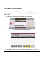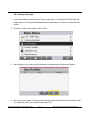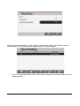
1
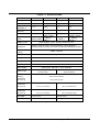
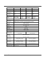
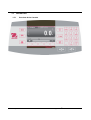
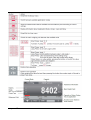
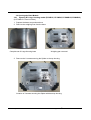
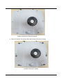
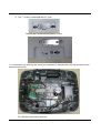
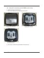
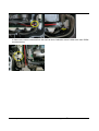
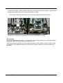
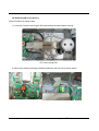
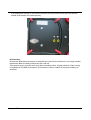
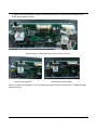
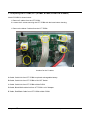
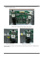
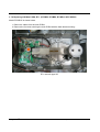
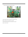
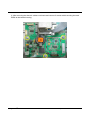
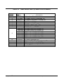
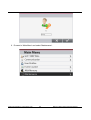
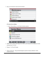
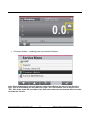
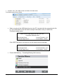
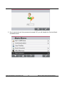
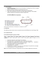
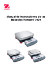
® Ranger 7000 Scale Service Manual TABLE OF CONTENTS Page No. 1 GETTING STARTED 1.1 INTRODUCTION 1.2 SERVICE FACILITIES 1.3 TOOLS AND TEST EQUIPMENT REQUIRED 1.4 SPECIFICATIONS 1.5 OPERATION 1.5.1 Overview of the Controls 1.5.2 Principle Functions and Main Menu. 2 DIAGNOSTIC GUIDE 2.1 TROUBLESHOOTING 2.2 SOFTWARE 2.3 DIAGNOSTIC GUIDE 3 MAINTENANCE / REPAIR PROCEDURES 3.1 PREVENTIVE MAINTENANCE 3.2 OPENING THE SCALE 3.2.1 Preparation for Opening Ranger 7000® Models 3.3 OPENING THE TERMINAL MODULE 3.3.1 Detaching the Terminal from the base. 3.3.2 Detaching the base RS422 cable from the Terminal 3.3.3 Dismantling the Terminal housing 3.4 OPENING THE BASE MODULE 3.4.1 Opening R71 large housing model 3.4.2 Opening R71 small housing mode 3.5 Replacing MFR Load cell, R71 3.6 Replacing SG Load cell, R71 3.7 REPLACING THE PRINTED CIRCUIT BOARD ASSEMBLIES (PCBA) 3.7.1 Terminal 3.7.2 Remove the TFT PCB 3.7.3 Removing MFR Main PCBA 3.7.4 Removing MFR LFT PCBA 3.7.5 Replacing SG LFT PCBA 3.7.6 Replacing SG Main PCBA 4 TESTING 4.1 TEST MASSES REQUIRED 4.1.1 OPERATIONAL TEST 4.2 LOAD CELL TEST USING RAMP 4.3 PERFORMANCE TESTS 4.3.1 Precision Test 4.3.2 Repeatability Test (non-approved models) 4.3.3 Linearity Test 4.3.4 Off-Center Load Test 5 PARTS LISTS & DIAGRAMS 5.1 TERMINAL SPARE PARTS 5.2 BASE SPARE PARTS (R71MD3 and R71MD6) 5.3 BASE SPARE PARTS (R71MD15 and R71MD35) 5.4 BASE SPARE PARTS (R71MHD3 and R71MHD6) 5.5 BASE SPARE PARTS (R71MHD15 and R71MHD35) Ohaus Corporation www.ohaus.com i ® Ranger 7000 Service Manual 4 4 4 5 5 8 8 10 11 11 11 12 14 14 15 15 15 15 16 18 22 22 25 29 32 34 34 36 39 41 43 45 48 48 49 49 49 49 50 52 53 55 56 58 60 62 64 TABLE OF CONTENTS Page No. 6 ACCESSING THE SERVICE MENU. 6.1 Accessing the Service Menu (Super Password) 6.2 Creating UserLogin 6.3 Under Service Menu 6.4 Maintenance (Diagnostic) 6.5 Disable 'Service Menu'. APPENDIX A – COMMUNICATION A.1 Scale Commands. A.2 RS232 (DB9) Pin Connections A.3 USB HOST A.3.1 Print Format A3.2 Print Out String for g, kg,lb, oz Units A3.3. Print Out String for lb:oz Units APPEDDIX BB.1 Software Installation & Software Selection B.2 Product Selection B.3 To Restore the EEPROM Data B.4 Com Port Configuration B.5 To Replace Load Cell B.6 Install New Main Printed Circuit Board (PCBA) B.7 Update the Software in the Scale B.8 Diagnostic 66 66 67 70 73 76 78 78 79 79 79 79 80 81 82 82 84 85 87 89 90 LIST OF TABLES TABLE NO. TITLE 1-1 Specifications 1-2 Menu and Screen Navigation 2-1 Diagnostic Guide 4-1 Calibration Mass Values 4-2 Repeatability Worksheet 4-3 Linearity Test – Reference and Load Masse 4-4 Off Center Load Mass Values 5-1 Terminal Spare Parts 5-2 Base Spare Parts (R71MD3 and R71MD6) 5-3 Base Spare Parts (R71MD15 and R71MD35) 5-4 Base Spare Parts (R71MHD3 and R71MHD6) 5-5 Base Spare Parts (R71MHD15 and R71MHD35) A-1 Interface Command List ® Ranger 7000 Service Manual ii Page No. Ohaus Corporation www.ohaus.com 6-7 10 16 51 54 55 56 59 61 63 65 67 80 TABLE OF CONTENTS Ohaus Corporation www.ohaus.com iii ® Ranger 7000 Service Manual 1 GETTING STARTED 1.1 INTRODUCTION This service manual contains the information needed to perform routine maintenance and service on the Ohaus Ranger 7000® Series scales. Familiarity with the scale’s Instruction Manual is assumed. The contents of this manual are contained in five chapters: Chapter 1 - Getting Started – Contains information on service facilities, tools, specifications, and the mechanical and electronic functions of the scale. Chapter 2 - Troubleshooting – Contains a diagnostic guide and error code table. Chapter 3 - Maintenance Procedures – Contains preventive maintenance procedures and disassembly, repair and replacement procedures. Chapter 4 - Testing – Contains a list of required test masses, an operational test, segment display test, performance tests and adjustments. Chapter 5 - Drawings and Parts Lists – Contains exploded views of Ranger 7000® scales identifying all serviceable components. Chapter 6 – Entering to Service Menu- Explains method to enter to Service Menu. Appendix A - Communication – Explains the scale communication information. 1.2 SERVICE FACILITIES To service a scale, the service area should meet the following requirements: • Should be temperature controlled and meet scale specifications for temperature environmental requirements. • Must be free of vibrations such as fork lift trucks close by, large motors, air currents or drafts from air conditioning/heating ducts, open windows, people walking by, fans, etc. • Area must be clean and free of excessive dust. • Work surface must be stable and level. • Scale must not be exposed to direct sunlight or radiating heat sources. • Handle all electronic assemblies with appropriate Electro-Static protection. Ohaus Corporation www.ohaus.com 4 ® Ranger 7000 Series Service Manual 1.3 TOOLS AND TEST EQUIPMENT REQUIRED • Common hand tools are sufficient to disassemble the Ranger 7000® scales. • A PC running Microsoft Windows XP or later. • Ranger 7000® Software Service Tool, PN 83032124 • RS232 Cable – Scale to PC PN 80500525 • Digital voltmeter (DVM) with an input impedance of at least 10 meg-ohms at 1 volt DC. • Masses as shown in Table 4-1. 1.4 SPECIFICATIONS Specifications for the Ohaus Ranger 7000® Scales are listed in Table 1-1. When a scale has been serviced, it must meet the specifications listed in the table. Before servicing the scale, determine what specifications are not met. Special Note regarding Approved scales: The specifications for the approved scales below are only for initial testing. These scales must be tested according to the requirements of the local Weights and Measures authority. Before returning the scale to service an approved representative of the local Weights and Measures authority must certify the scale. Ambient conditions Indoor use only Altitude: Up to 2000 m Specified Temperature range: 10 °C to 30 °C (R71MH D3/6/15/35 models) -10 °C to 40 °C (R71MD3/6/15/35 models) Humidity: maximum relative humidity 80 % for temperatures up to 30 °C decreasing linearly to 50 % relative humidity at 40 °C Mains supply voltage fluctuations: up to ±10 % of the nominal voltage Installation category II Pollution degree: 2 Operability is assured at ambient temperatures between 5 °C to 40 °C. Materials Base Housing; die-cast Aluminum, Painted Terminal housing: die-cast Aluminum, Painted Weighing Pan: 304 Stainless Steel ® Ranger 7000 Series Service Manual 5 Ohaus Corporation www.ohaus.com TABLE 1-1 SPECIFICATIONS MODEL R71MHD3 R71MHD6 R71MHD15 R71MHD35 Capacity 3000 g 6000 g 15000 g 35000 g Readability d 0.01 g 0.02 g 0.1 g 0.1 g 0.1 g 0.2 g 1g 1g 0.01 g 0.02 g 0.1 g 0.1 g Linearity ± 0.02 g ± 0.2 g Span Calibration Points 500 g, 1500 g, 2000 g, 3000 g ± 0.04 g 1000 g, 2000 g, 4000 g, 6000 g ± 0.2 g 10000 g, 20000 g, 30000 g, 35000 g, Approved Readability e Repeatability (std. dev.) Weighing units Applications gram, kilogram, ounce, pound, pound:ounce, ton Weighing, Parts Counting, Percent Weighing, Check Weighing, Dynamic Weighing, Filling, Formulation, Differential Weighing, Density Stabilization time (typical) Within 1 second Display TFT Graphic LCD Display size 4.3 in Backlight White LED Communication RS-422, USB Power supply Power Input: 100-240 V~ 0.5 A 50/60 Hz Platform size 240 x 240 mm 377 x 311 mm 9.4 x 9.4 inch 14.8 x 12.2 inch Terminal Housing dimensions (W x D x H) Base Housing dimensions 5000 g, 10000 g, 15000 g 267 x 118 x 72 mm 10.5 x 4.6 x 2.8 in 280 x 280 x 114 mm 377 x 311 x 128 mm (W x D x H) 11 x 11 x 4.5 inch 14.9 x 12.2 x 5 inch Assembled dimensions 280 x 420 x 114 mm 377 x 467 x 128 mm (W x D x H) 11 x 11 x 4.5 inch 14.9 x 18.4 x 5 inch Net weight 7.2 kg / 16 lb Shipping weight 9.2 kg / 20.3 lb Ohaus Corporation www.ohaus.com 10.9 kg / 24 lb 14.4 kg / 31.7 lb 6 ® Ranger 7000 Series Service Manual MODEL R71MD3 R71MD6 R71MD15 R71MD35 Capacity 3000 g 6000 g 15000 g 35000 g Readability d 0.05 g 0.1 g 0.2 g 0.5 g 0.5 g 1g 2g 5g 0.05 g 0.1 g 0.2 g 0.5 g Linearity ± 0.1 g ± 0.4 g Span Calibration Points 500 g, 1500 g, 2000 g, 3000 g ± 0.2 g 1000 g, 2000 g, 4000 g, 6000 g ±1g 10000 g, 20000 g, 30000 g, 35000 g Approved Readability e Repeatability (std. dev.) Weighing units Applications 5000 g,10000 g, 15000 g gram, kilogram, ounce, pound, pound:ounce, ton Weighing, Parts Counting, Percent Weighing, Check Weighing, Dynamic Weighing, Filling, Formulation, Differential Weighing, Density Stabilization time (typical) Within 1 second Display TFT Graphic LCD Display size 4.3 in Backlight White LED Communication RS-232, USB Power supply Power Input: 100-240 V~ 0.5 A 50/60 Hz Platform size 280 x 280 mm 377 x 311 mm 11 x 11 inch 14.8 x 12.2 inch Terminal Housing dimensions (W x D x H) 267 x 118 x 72 mm 10.5 x 4.6 x 2.8 in Base Housing dimensions 280 x 280 x114 mm 377 x 311 x 128 mm (W x D x H) 9.4 x 9.4 x 4.5 inch 14.9 x 12.2 x 5 inch Assembled dimensions 240 x 420 x 114 mm 377 x 467 x 128 mm (W x D x H) 17.4 x 16.5 x 4.5 inch 14.9 x 18.4 x 5 inch Net weight 6.8 kg / 15 lb Shipping weight 8.5 kg / 18.7 lb ® Ranger 7000 Series Service Manual 9.9 kg / 21.8 lb 13.4 kg / 29.5 lb 7 Ohaus Corporation www.ohaus.com 1.5 OPERATION 1.5.1 Overview of the Controls Ohaus Corporation www.ohaus.com 8 ® Ranger 7000 Series Service Manual ® Ranger 7000 Series Service Manual 9 Ohaus Corporation www.ohaus.com 1.5.2 Principle Functions and Main Menu. 1-2 Menu and Screen Navigation Ohaus Corporation www.ohaus.com 10 ® Ranger 7000 Series Service Manual 2 DIAGNOSTIC GUIDE This section of the manual contains troubleshooting information. Information is contained to isolate specific problems using Table 2-1, Diagnostic Guide. Follow all directions step by step. Make certain that the work area is clean. Handle scale components with care. Use appropriate electro-static protection devices to prevent damage to the sensitive electronic components. 2.1 TROUBLESHOOTING General procedures for Troubleshooting: 1. Do the most obvious, user-level remedies. 2. Visual Check: - Check that the internal parts are clean and free from debris. - Examine the scale for damage or signs of abuse, replace any damaged items. 3. Use the error code table for solutions for specific codes. 4. Use the Diagnostic Guide; locate the symptom then follow the suggested remedies in order. Note: Allow equipment to warm up for 60 minutes on precision models for optimal weighing performance. Allow 4 hours for analytical models to stabilize. 2.2 SOFTWARE In most cases understanding the customer’s problem with the scale is easy. Physical damage, displayed error code, failure to power up and obvious poor performance can usually be repaired by following the instructions in the following sections. Some scale issues may be software related. New releases of the software may correct these issues. The Ranger 7000® Scale has upgradeable software in the Terminal and the Base modules. The software revision in the scale can be seen when the scale is in standby mode or during the power up sequence. The software version is displayed in the lower right hand corner of the screen. The screen will show: Model number Capacity and readability Software Revision “Terminal” / “Base” for example: Ranger 7000® R71MD3 3000g x 0.05g Version 1.00 / 0.14 The scale software can also be retrieved by sending a “PV” command via the RS232 or other interface. ® Ranger 7000 Series Service Manual 11 Ohaus Corporation www.ohaus.com 2.3 DIAGNOSTIC GUIDE 2.1 Diagnostic Guide Error Code EEP Error Power on Overload Description EEPROM Checksum Error Power On Error Power on Underload Power On Error Overload Over Range Error Underload Under Range Error Tare Error Tare out of range Error Display Overflow Display Overflow No Calibration Calibration data error ------- Busy message --NO-- Action not allowed message Calibration Error Calibration Error Low Reference Reference Error Ohaus Corporation www.ohaus.com Low reference weight warning message Unacceptable reference weight message 12 Cause Corrupted EEPROM data Weight reading exceeds Power On Zero limit. Weight reading below Power On Zero limit. Weight reading exceeds Overload limit. Weight reading below Underload limit. Tared at one unit but after switching to another unit the tare value exceeds the maximum. Weight exceeds 6 digits. Calibration data does not exist. Displayed during tare setting, zero setting, printing Function not executed. Calibration value outside allowable limits Average Piece Weight too small. (Warning) Reference Weight too small. The weight on the pan is too small to define a valid reference weight. ® Ranger 7000 Series Service Manual Diagnosis: 1. Isolate and identify the symptom. 2. Refer to Troubleshooting tables and locate the symptom. 3. Follow the suggested remedies in the order they appear. 4. Perform the indicated checks, or see the appropriate section of the manual. 5. Repair or replace the defective section of the scale. NOTE: If more than one symptom is observed, approach one area at a time, and remember that the symptoms may be interrelated. If a problem arises that is not covered in this manual, contact Ohaus Corporation for further information. ® Ranger 7000 Series Service Manual 13 Ohaus Corporation www.ohaus.com 3 MAINTENANCE / REPAIR PROCEDURES 3.1 PREVENTIVE MAINTENANCE Ohaus scales are precision instruments and should be carefully handled, stored in a clean, dry, dust-free area, and cleaned periodically. Follow these precautionary steps: • When a scale has had chemicals or liquids spilled on it, all exterior surfaces should be cleaned as soon as possible with warm water on a damp cloth. • Do not leave a mass on the scale when the scale is not in use. • Allow time for the scale to stabilize after moving it from an area which is at a different temperature than the area where it is to be operated. Allow one hour for each 5°F (2.7°C) temperature change before using the scale. After temperature stabilization, allow an additional 60 minutes after turning the scale on, for the scale electronics to stabilize. Preventive Maintenance Checklist The scale should be inspected and checked regularly, as follows: 1. Remove the Pan and Sub Pan to inspect and clean the area beneath the Pan. 2. Clean the outside of the scale using a damp cloth with warm water. 3. Check the Power Cord for broken or damaged insulation. 4. Make a visual inspection for faulty connectors, wiring, and loose hardware. CAUTION DO NOT USE CHEMICAL CLEANERS OR SOLVENTS OF ANY TYPE. SOME CLEANERS ARE ABRASIVE AND MAY AFFECT THE SCALE’S FINISH. Ohaus Corporation www.ohaus.com 14 ® Ranger 7000 Series Service Manual 3.2 OPENING THE SCALE Opening the Ranger 7000® scale varies slightly according to the specific model, as detailed below. Use these procedures in order to replace the Load Cell, the Printed Circuit Board or other components. Common hand tools are sufficient to disassemble the Ranger 7000® scale s. Preparation for Opening Ranger 7000® Models 3.2.1 1. Turn the scale off and unplug the power cord before you begin. 2. Disconnect any communication or other option cables. 3.3 OPENING THE TERMINAL MODULE *Below show a Ranger7000 MFR small housing model R71MHD6. 3.3.1 Detaching the Terminal from the base. 1. Switch off and disconnect the scale from main power supply. 2. Detach the display terminal from the base by pressing both release buttons at the same time as show below picture. After that pull the Terminal towards you (outward) until the Terminal is detached from the base as show below. ® Ranger 7000 Series Service Manual 15 Ohaus Corporation www.ohaus.com 3.3.2 Detaching the base RS422 cable from the Terminal. 1. Dismantle the base RS422 cable from the Terminal. 2. Removing the docking bracket from the Terminal. Ohaus Corporation www.ohaus.com 16 ® Ranger 7000 Series Service Manual 3. Flip the Terminal around locate the 3 screws as shown and remove the screws which are mounting the bracket to the Terminal as shown below and separate the docking bracket from the Terminal. ® Ranger 7000 Series Service Manual 17 Ohaus Corporation www.ohaus.com 3.3.3 Dismantling the Terminal housing. 1. Remove the 5 screws securing the housing. • 4 screws are located underneath the rubber cover at 4 corners of the bottom housing. Remove the rubber cover and you will be able to locate and remove the 4 hidden screws. Ohaus Corporation www.ohaus.com 18 ® Ranger 7000 Series Service Manual 2. After removing the screws which are securing the bottom housing with the top housing turn the terminal module over. After that carefully lift up the top housing, DO NOT remove the top housing completely away from the bottom housing because the Terminal keypad overlay ribbon cable and TFT display ribbon cable are still attached with the Terminal main PCBA. ® Ranger 7000 Series Service Manual 19 Ohaus Corporation www.ohaus.com 3. Disconnect the ribbon cable connecting the TFT with Terminal PCBA by using a thin screw driver blade radiated the back cable-lock on the connector 90⁰ so that it is perpendicular to the cable as show in below pictures. Connector lock with ribbon cable attaches Connector open with TFT ribbon cable remove. 4. Disconnect the keypad overlay ribbon cable from the Terminal PCBA by unfasten the connector as shown in below pictures. Ohaus Corporation www.ohaus.com 20 ® Ranger 7000 Series Service Manual Shift the connector outward Connector open and keypad overlay cable remove 5. Both bottom and top Terminal housing are now separated. ® Ranger 7000 Series Service Manual 21 Ohaus Corporation www.ohaus.com 3.4 Opening the Base Module 3.4.1 Opening R71 large housing model (R71MD15, R71MD35, R71MHD15,R71MHD35) (A R71MD15 is used in below). 1. Prepare the bases as mention above. 2. Remove the weighing Pan from the base. Complete set of Large Housing base Weighing pan removed 3. Remove the 2 screws securing the Spider to the top housing. Location of 2 screws securing the Spider with base top housing. Ohaus Corporation www.ohaus.com 22 ® Ranger 7000 Series Service Manual Spider removed from base top housing. 4. Remove 6 screws securing the base top housing and bottom housing. Location of the first 6 screws. ® Ranger 7000 Series Service Manual 23 Ohaus Corporation www.ohaus.com 5. The 7th screw is underneath the LFT cover. Remove the 2 screws securing the LFT cover. 7th screw expose, by removing this screw you will be able to dismantle the base top housing from the base bottom housing. R71 SG Base top housing removed. Ohaus Corporation www.ohaus.com 24 ® Ranger 7000 Series Service Manual 3.4.2 Opening R71 small housing model (R71MHD6 is used in below). 6. Prepare the bases as mention above. 7. Remove the weighing Pan and Wind Ring from the base. Complete set of MFR base Weighing pan removed Wind Ring removed. 8. Remove the 2 screws securing the Spider to the top housing. ® Ranger 7000 Series Service Manual 25 Ohaus Corporation www.ohaus.com Location of 2 screws securing the Spider with base top housing. Spider removed from base top housing. 9. Remove 5 screws securing the base top housing and bottom housing. Ohaus Corporation www.ohaus.com 26 ® Ranger 7000 Series Service Manual 10. The 5th screw is underneath the LFT cover. Remove the 2 screws securing the LFT cover. 5th screw expose, by removing this screw you will be able to dismantle the base top housing from the base bottom housing. ® Ranger 7000 Series Service Manual 27 Ohaus Corporation www.ohaus.com Ohaus Corporation www.ohaus.com 28 ® Ranger 7000 Series Service Manual 3.5 Replacing MFR Load cell, R71. Model R71MHD6 is shown below. 1. Locate the 4 screws securing the MFR load cell with the base bottom housing. R71 load cell type MFR. 3. Remove the cable connecting the Base PCBA with MFR load cell as shown below. 4. Remove the Red and White cable connecting the base PCBA with LFT PCBA. ® Ranger 7000 Series Service Manual 29 Ohaus Corporation www.ohaus.com 5. Remove the cable connected from the load cell Auto Calibration motor PCBA to the main PCBA as shown below. Ohaus Corporation www.ohaus.com 30 ® Ranger 7000 Series Service Manual 6. After removing the 3 cables mention above the next step would be removing the 4 screws which are securing the MFR load cell from the base bottom housing. Once these 4 screws are removed you can securely remove the cell from the base. Location of the screws securing the MFR cell from the base bottom housing. Re-Assembly: Reverse the disassembly procedure to assemble the scale. Ensure that there is no foreign material between the Base mounting surfaces and the Load cell. Take special care to route the wires and cables according to their original positions. Proper routing is important for RFI/ESD performance. Ensure that the wires or cables are not pinched during reassembly. ® Ranger 7000 Series Service Manual 31 Ohaus Corporation www.ohaus.com 3.6 Replacing SG Load cell, R71. Model R71MD15 is shown below. 1. Locate the 2 screws securing the SG load cell with the base bottom housing. R71 load cell type SG. 2. Remove the cable connecting the Base PCBA with SG load cell as shown below. Ohaus Corporation www.ohaus.com 32 ® Ranger 7000 Series Service Manual 3. By holding the load cell in one hand unscrew the 2 screws which securing the SG load cell located at the bottom of the base housing. Re-Assembly: Reverse the disassembly procedure to assemble the scale. Ensure that there is no foreign material between the Base mounting surfaces and the Load cell. Take special care to route the wires and cables according to their original positions. Proper routing is important for RFI/ESD performance. Ensure that the wires or cables are not pinched during reassembly. ® Ranger 7000 Series Service Manual 33 Ohaus Corporation www.ohaus.com 3.7 REPLACING THE PRINTED CIRCUIT BOARD ASSEMBLIES (PCBA) Before working with the exposed PCBAs appropriate ESD protection must be taken to prevent damage to the sensitive electronic components. It is recommended that a conductive mat with wrist straps be used when working with electronic components. 3.7.1 Terminal A) Separate the Terminal PCBA from the bottom housing by removing 4 screws, one 8PIN connector on top of the PCBA and another 2 screws securing the RS232 port to the bottom housing. (Located at the back of the Terminal) Location of the 4 screws and 8PIN connector on the Terminal PCBA. B) Remove the 8PIN connector by gently pulling up the connector. Showing 8PIN Connector attached and detached from Terminal PCBA. Ohaus Corporation www.ohaus.com 34 ® Ranger 7000 Series Service Manual C) Removing the 2 screws securing the RS232 Port to the bottom housing. R71 RS232 port located behind the Terminal. 2 screws securing the RS232 port against the Terminal housing removed. (Remember to place back these 2 screws after repairing) ® Ranger 7000 Series Service Manual 35 Ohaus Corporation www.ohaus.com Terminal PCBA taken out from Terminal bottom housing. 3.7.2 Remove the TFT PCB A) Remove the two screws holding the TFT in place as shown below. Location of the 2 screws holding the TFT in place against the Terminal Top housing. (Note the position of the two RED holders) Ohaus Corporation www.ohaus.com 36 ® Ranger 7000 Series Service Manual Correct RED holder position Wrong RED holder position 2 screws and Red Holder removed. B) Gently remove the TFT from the top housing and place in a secure area. *When re-installing the TFT PCB make sure the surface on the TFT PCB and Top housing is clean and free from dust and debris. ® Ranger 7000 Series Service Manual 37 Ohaus Corporation www.ohaus.com TFT PCB removed from Terminal Top housing. R71, 4.3" TFT Display PCB P/N: 30095940 Ohaus Corporation www.ohaus.com 38 ® Ranger 7000 Series Service Manual 3.7.3 Removing MFR Main PCBA, R71. (R71MHD3, R71MHD6, R71MHD15 & R71MHD35) Below show model R71MHD6. 1) Remove 5 cables from the main PCBA. 2) Loosen the 2 screws securing the main PCBA with the base bottom housing. 1. Remove the below cables from the main PCBA. Location of the 5 cables on the main PCBA. A Cable, Red/Black Cable from main PCBA to LFT PCBA B Cable, RS422 Cable from main PCBA to R71 Display Terminal. C Cable, Cable from main PCBA to LFT PCBA. D Cable, Cable from MFR cell to main PCBA. E Cable, Cable from AutoCal motor PCBA to main PCBA. ® Ranger 7000 Series Service Manual 39 Ohaus Corporation www.ohaus.com 2. After removing the above 5 cables now locate and loosen 2 screws which securing the LFT PCBA to the bottom housing. Location of the 2 screws securing the main PCBA to the bottom housing. Screw at Lock position Screw at Un-Lock position Once you set the two screws in Un-Lock position you will be able to remove the Main PCBA from the bottom housing. Ohaus Corporation www.ohaus.com 40 ® Ranger 7000 Series Service Manual 3.7.4 Removing MFR LFT PCBA, R71. (R71MHD3, R71MHD6, R71MHD15 & R71MHD35) Model R71MHD6 is shown below. 1. Remove the 5 cables from the LFT PCBA. 2. Loosen the 2 screws securing the LFT PCBA with the base bottom housing. 1. Remove the below 5 cables from the LFT PCBA. Location for the 5 cables. A Cable, Cable link from LFT PCBA to optional rechargeable battery. B Cable, Cable link from LFT PCBA to ON OFF Switch. C Cable, Cable link from LFT PCBA to Main PCBA. D Cable, Black/While cable link from LFT PCBA to AC Adapter. E Cable, Red/White Cable from LFT PCBA to Main PCBA. ® Ranger 7000 Series Service Manual 41 Ohaus Corporation www.ohaus.com 2. After removing the above 5 cables now locate and loosen 2 screws which securing the LFT PCBA to the bottom housing. Picture shows 5 cables removed, location of the 2 screws. Screw at Lock position Screw at Un-Lock position Once you set the two screws in Un-Lock position you will be able to remove the LFT PCBA from the bottom housing. Ohaus Corporation www.ohaus.com 42 ® Ranger 7000 Series Service Manual 3.7.5 Replacing SG LFT PCBA, R71. (R71MD3, R71MD6, R71MD15 & R71MD35) Model R71MD6 is shown below. 1. Remove 5 cables from the LFT PCBA. 2. Loosen the 2 screws securing the LFT PCBA with the base bottom housing. 1. Remove the below 5 cables from the LFT PCBA. Location for the 5 cables. A Cable, Cable link from LFT PCBA to optional rechargeable battery. B Cable, Cable link from LFT PCBA to ON OFF Switch. C Cable, Cable link from LFT PCBA to Main PCBA. D Cable, Black/While cable link from LFT PCBA to AC Adapter. E Cable, Red/Black Cable from LFT PCBA to Main PCBA. ® Ranger 7000 Series Service Manual 43 Ohaus Corporation www.ohaus.com 2. After removing the above 5 cables now locate and loosen 2 screws which securing the LFT PCBA to the bottom housing. Picture shows 5 cables removed, location of the 2 screws. Screw at Lock position Screw at Un-Lock position Once you set the two screws in Un-Lock position you will be able to remove the LFT PCBA from the bottom housing. Ohaus Corporation www.ohaus.com 44 ® Ranger 7000 Series Service Manual 3.7.6 Replacing SG Main PCBA, R71. (R71MD3, R71MD6, R71MD15 & R71MD35) Model R71MD15 is shown below. 1. Remove 4 cables from the main PCBA. 2. Remove the 3 screws securing the main PCBA with the base bottom housing. R71 load cell type SG. ® Ranger 7000 Series Service Manual 45 Ohaus Corporation www.ohaus.com 1. Remove the below cables from the main PCBA. Location for the 4 cables. A Cable, RS422 cable from main PCBA to R71 Display Terminal. B Cable, Cable link from main PCBA to LFT PCBA. C Cable, Red White Cable link from main PCBA to LFT PCBA. D Cable, Load Cell cable. Ohaus Corporation www.ohaus.com 46 ® Ranger 7000 Series Service Manual 2. After removing the above 4 cables now locate and remove 3 screws which securing the main PCBA to the bottom housing. ® Ranger 7000 Series Service Manual 47 Ohaus Corporation www.ohaus.com 4 TESTING Before and after servicing a Ranger 7000® scale, an operational test and various performance tests should be made to confirm if the scale meets specifications. Turn the scale on and allow it to warm up for at least one hour before performing these tests. The Analytical models need up to 4 hours to stabilize. NOTE: Make sure the test area is free from drafts and that the scale rests on a level and vibration-free surface. The Analytical models especially need a solid platform, such as a stone table. 4.1 TEST MASSES REQUIRED The masses required to test the Ohaus Ranger 7000® scales must meet the requirements of the ASTM or OIML Tolerances listed in the table. Poor quality calibration masses be the can cause of frustrating diagnostics. TABLE 4-1 Ohaus Corporation www.ohaus.com CALIBRATION MASS VALUES 48 ® Ranger 7000 Series Service Manual 4.1.1 OPERATIONAL TEST 1. Connect a functioning Power Adapter to the scale. 2. Plug the Power Cord into a suitable power source. 3. Verify that the scale start up sequence occurs properly. Note any error codes. 4.2 LOAD CELL TEST USING RAMP To test the Load Cell using RAMP, see Chapter 6.3. 4.3 PERFORMANCE TESTS Accurate performance of the Ranger 7000® scale s is determined by a series of four performance tests. The displayed readings are compared with the tolerances listed in Tables 1-1. Tolerance values are expressed in counts. A one-count difference is shown in the last digit on the scale display. The following performance tests are used to evaluate scale operation before and after repairs. The scale must meet the requirements specified in each test as well as the specifications listed in Table 1-1. Before proceeding with the following tests, the scale should be warmed up (60 minutes) and calibrated. (See Appendix A). 4.3.1 Precision Test The Precision Test is a quick test that measures the deviation of a limited number of weight readings. If the scale passes the precision test than the following tests should be performed. Note: This is a reference test for approved models (OIML and NTEP). It is not a required test but it can be used to determine if the scale is working properly. 1. The reading on the display should be 0g. 2. Select a mass weighing near the maximum capacity of the scale, and place it on the center of the Pan. Observe and record the reading. 3. Remove the mass. The reading should return to 0g ± 1d. 4. Repeat this test three times. The readings should be within ± 1d. If so, the scale passes the Precision Test. If the deviation for any set of readings (using the same mass placed on the center of the Pan) is greater than 1d, the scale does not meet the precision specification. Inspect and correct the following areas: - Check for mechanical obstructions. Any foreign object pressing any part of the moving assemblies will cause a scale to fail the Precision Test. Inspect and correct as necessary. - If the scale does not meet specifications, move it to a suitable location, ensure that it is level, and try again. If it still does not meet specifications, perform a service calibration, and try again. (See Appendix B for Service Calibration) - If the scale does not pass this test, the Load Cell may need to be replaced. ® Ranger 7000 Series Service Manual 49 Ohaus Corporation www.ohaus.com 4.3.2 Repeatability Test (non-approved models) The repeatability specification is defined as the Standard Deviation value derived from a set of weight readings. This test uses more weight data than the Precision Test and will allow for occasional weight deviations due to testing variations. Note: The required method for approved models (OIML and NTEP) is shown in the following section. Requirements: • To perform this test a single mass must be used for all readings. • The test mass should be approximately ½ of the capacity of the instrument. • Wear gloves when handling the mass. Set Up: Before starting a repeatability test, set up the instrument as follows. Enter the service menu (see Chapter 6) and adjust and record the following settings: • Set the Stability setting to 0.5d (its lowest setting). • Set the Filter level to “Middle”. • Set the AZT (Auto Zero Tracking) to .5d (its lowest setting). Do not turn it off. Enter the User Menu (see 1.8.1) and adjust the following settings: • Set the instrument to display the same units as the performance specifications. (Usually kg, g, or mg) Record Test Parameters: • Stability Setting = ____________ • Filter Level Setting = ____________ • Auto Zero Tracking Setting = ____________ • Displayed Units = ____________ • Mass Used = ____________ Test Procedure: 1. Zero the instrument. 2. Using a test mass approximately half the capacity of the instrument, place the mass on the center of platform. Record the reading on the worksheet provided. 3. Remove the mass from the platform. 4. Repeat this test starting at Step 1 until you record a total of ten readings. Fill in the worksheet with the ten (10) readings. Ohaus Corporation www.ohaus.com 50 ® Ranger 7000 Series Service Manual TABLE 4-2: REPEATABILITY WORKSHEET n Reading Delta = Reading – Mean Delta x Delta 1 2 3 4 5 6 7 8 9 10 n = number of Reading Mean = Sum of readings / 10 Delta = Reading – Mean Standard Deviation = Square Root of (sum of (Delta x Delta) / 9) 5. Add the ten readings and divide the total by 10 to find the Mean (average). Mean = (Reading 1 + Reading 2 + Reading 3 + Reading 4 + Reading 5+ Reading 6 + Reading 7+ Reading 8 + Reading 9 + Reading 10) / 10 Mean =________ 6. Calculate the Delta for each reading and record in the work sheet. Delta = Reading – Mean 7. Calculate the Delta x Delta for each reading and record in worksheet. 8. Add the ten Delta x Delta values and divide by 9 9. Calculate the Standard Deviation by applying the square root of the result from step 8. Standard Deviation =___________ Note: If the scale does not meet specifications, check environmental conditions, ensure that the scale is level, and try again. If it still does not meet specifications, perform a service calibration, and try again. (See Appendix B for Service Calibration). ® Ranger 7000 Series Service Manual 51 Ohaus Corporation www.ohaus.com Repeatability Test – Approved models This test is a variation of the test above. Rather than determining acceptance based on the standard deviation of the errors, MPE is used. The other variation is that 2 series of weighings are used, one near 50% of max and the other near 100% of maximum capacity. 1. See Table 1-1 to determine the two weight values that must be used. 2. Record 10 reading using each weight value. Zero the scale between each reading if necessary. 3. The difference between the results of the 10 readings must be less than the absolute value of the Maximum Permissible Error (MPE) for the load. The MPE for each load in grams is given in Table 1-1. 4.3.3 Linearity Test This test is used to determine the linearity of the unit throughout its operating range. The masses used to perform this test can be utility masses. This is a reference test for approved scale s as there is no linearity specification. The approved models should be able to pass this test so it is still valid to determine scale performance. NOTE: The scale must pass the Precision and Repeatability Tests, and be calibrated before the Linearity Test is performed. TABLE 4-3 LINEARITY TEST - REFERENCE AND LOAD MASSES Model Load 1 Load 2 Load 3 R71MHD3 0kg 1.5kg 3kg R71MHD6 0kg 3kg 6kg R71MHD15 0kg 10kg 15kg R71MHD35 0kg 20kg 35kg R71MD3 0kg 1.5kg 3kg R71MD6 0kg 3kg 6kg R71MD15 0kg 10kg 15kg R71MD35 0kg 20kg 35kg NOTE: All masses are nominal values. Be certain to use the same reference mass throughout the procedure. 1. Place the Reference Mass on the scale, record the weight and remove. 2. Place Load 1 on the scale and press TARE. 3. Place the test mass on the scale, record the weight and remove. 4. Place Load 2 on the scale and press TARE. 5. Place the test mass on the scale, record the weight and remove. 6. Place Load 3 on the scale and press TARE. 7. Place the test mass on the scale and record the weight. 8. The difference in the weights of the test mass should be within the tolerance in Table 4-2. If the differences are out of tolerance, verify the test conditions and repeat the test. 9. If the scale remains out of tolerance, the Load Cell may need to be replaced. Ohaus Corporation www.ohaus.com 52 ® Ranger 7000 Series Service Manual 4.3.4 Off-Center Load Test The Off-Center Load Test is used to determine whether displayed weight values are affected by moving the sample to different areas of the Pan. OCL test may also be referred to as a Shift Test (NTEP) or an Eccentricity Test (OIML). The test weight used in this test 1/3 the capacity of the scale. See table for the test weight values. TABLE 4-4 OFF CENTER LOAD MASS VALUES Model OCL Mass Value Notes R71MHD3 0 kg, 1.5 kg, 3 kg R71MHD6 0 kg, 3 kg, 6 kg R71MHD15 0 kg, 10 kg, 15 kg 2. Use large weights where possible. Smaller weights can be R71MHD35 0 kg, 20 kg, 35 kg stacked on the larger but a stability problem may occur if many R71MD3 0 kg, 1.5 kg, 3 kg smaller weights are used. If weights cannot be stacked they R71MD6 0 kg, 3 kg, 6 kg R71MD15 0 kg, 10 kg, 15 kg R71MD35 0 kg, 20 kg, 35 kg 1. The class of test weight to be use during OCL is not critical. must be placed uniformly over the segment. The test positions (A-D) must be centrally located in each segment. B C B C A D A D Round Pan Rectangular Pan Procedure: 1. Set AZT (Auto Zero Tracking) to off. This setting is located in Menu - Scale Setup - AZT menu. 2. Place the test weight in the center of the Weighing Pan. 3. Tare the scale. 4. Move the weight to location A and record the reading (when stability indicator comes on). 5. Move the weight to location B and record the reading. 6. Move the weight to location C and record the reading. 7. Move the weight to location D and record the reading. 8. Maximum allowable change in displayed weight readings for each of the four positions can be found in Specifications Tables (Chapter 1). If this maximum is exceeded verify the test conditions and retest the scale. If there is no improvement the load-cell must be replaced. ® Ranger 7000 Series Service Manual 53 Ohaus Corporation www.ohaus.com Note: In high resolution scales (Class I) it may be necessary to zero or tare between each location. Ohaus Corporation www.ohaus.com 54 ® Ranger 7000 Series Service Manual 5 PARTS LISTS & DIAGRAMS This section of the manual contains parts lists and exploded views for the Ranger 7000® scale s. These are designed to identify the parts which can be serviced on the scale in the field. The parts list and exploded views are separated into separate sections for the Terminal and the Base. To order spare parts, identify the required item in the exploded views and parts list, then use the Spare Parts List to obtain the current part number for this item. NOTE: In all cases where a part is replaced, the scale must be thoroughly checked after the replacement is made. The scale MUST meet the parameters of all applicable specifications in this manual. If further technical information is needed, please contact your local Ohaus office, or www.ohaus.com. ® Ranger 7000 Series Service Manual 55 Ohaus Corporation www.ohaus.com 5.1 TERMINAL SPARE PARTS Ohaus Corporation www.ohaus.com 56 ® Ranger 7000 Series Service Manual TABLE 5-1 Drawing Item 1 2 3 4 5 6 ® Part Number 30095939 30095940 30095930 30103748 30095941 30095907 Ranger 7000 Series Service Manual TERMINAL SPARE PARTS Description SP Overlay R71 Terminal SP 4.3" TFT Display R71 Terminal SP PCBA, Terminal R71 SP 8PIN Connector Terminal, R71 SP Bracket, Docking, R71 SP Hardware Kit, R71 57 Ohaus Corporation www.ohaus.com 5.2 BASE SPARE PARTS (R71MD3 and R71MD6) Ohaus Corporation www.ohaus.com 58 ® Ranger 7000 Series Service Manual TABLE 5-2 Drawing Item 1 2 3 4 5 6 7 8 9 10 11 ® BASE SPARE PARTS (R71MD3 AND R71MD6) Part Number 30095934 30113444 30041419 30095908 30095907 30095937 30076250 30095909 30041267 30041462 30041463 30041464 30041465 30041466 30041469 30095936 30035606 30095932 30095933 30078209 Ranger 7000 Series Service Manual Description SP Pan, SM, SG, R71 SP Rubber Parts Kit, Small base, R71 SP Adapter, with-cable, EX HiCap, R71 SP Cables Kit, R71 SP Hardware Kit, R71 SP SG Loadcell, 5kg, R71 SP PCBA, LFT, EX HiCap, R71 SP PCBA, Base, SG, R71 SP Power-Cord US EX HiCap, R71 SP Power-Cord EU EX HiCap, R71 SP Power-Cord CN EX HiCap, R71 SP Power-Cord UK EX HiCap, R71 SP Power-Cord AU EX HiCap, R71 SP Power-Cord JP EX HiCap, R71 SP Power-Cord KR EX HiCap, R71 SP RS422 Cable Base R71 SP Feet Kit R21, R31, V71, V22, V41, R71 SP Packaging Assembly,SM,R71 SP Packaging Assembly,LA,SG,R71 Box,SM,R71 59 Ohaus Corporation www.ohaus.com 5.3 BASE SPARE PARTS (R71MD15 and R71MD35) Ohaus Corporation www.ohaus.com 60 ® Ranger 7000 Series Service Manual TABLE 5-3 Drawing Item 1 2 3 4 5 6 7 8 9 10 11 ® BASE SPARE PARTS (R71MD15 AND R71MD35) Part Number 30095934 30113444 30041419 30095908 30095907 30095937 30076250 30095909 30041267 30041462 30041463 30041464 30041465 30041466 30041469 30095936 30035606 30095932 30095933 30078209 Ranger 7000 Series Service Manual Description SP Pan, SM, SG, R71 SP Rubber Parts Kit, Small base, R71 SP Adapter, with-cable, EX HiCap, R71 SP Cables Kit, R71 SP Hardware Kit, R71 SP SG Loadcell, 5kg, R71 SP PCBA, LFT, EX HiCap, R71 SP PCBA, Base, SG, R71 SP Power-Cord US EX HiCap, R71 SP Power-Cord EU EX HiCap, R71 SP Power-Cord CN EX HiCap, R71 SP Power-Cord UK EX HiCap, R71 SP Power-Cord AU EX HiCap, R71 SP Power-Cord JP EX HiCap, R71 SP Power-Cord KR EX HiCap, R71 SP RS422 Cable Base R71 SP Feet Kit R21, R31, V71, V22, V41, R71 SP Packaging Assembly,SM,R71 SP Packaging Assembly,LA,SG,R71 Box,SM,R71 61 Ohaus Corporation www.ohaus.com 5.4 BASE SPARE PARTS (R71MHD3 and R71MHD6) Ohaus Corporation www.ohaus.com 62 ® Ranger 7000 Series Service Manual TABLE 5-4 Drawing Item 1 2 3 4 5 6 7 8 9 10 11 ® BASE SPARE PARTS (R71MHD6 AND R71MHD6) Part Number 30095935 30113444 30041419 30095908 30095907 30095903 30076250 30111916 30041267 30041462 30041463 30041464 30041465 30041466 30041469 30095936 30035606 30095932 30095933 30078209 Ranger 7000 Series Service Manual Description SP Pan,SM ,MFR, R71 SP Rubber Parts Kit, Small base, R71 SP Adapter, with-cable, Ex HiCap, R71 SP Cables Kit, R71 SP Hardware Kit, R71 SP MFR Loadcell 4kg, R71 SP PCBA,LFT,EX HiCap, R71 SP PCBA, Base, MFR,R71 SP Power-Cord US EX HiCap, R71 SP Power-Cord EU EX HiCap, R71 SP Power-Cord CN EX HiCap, R71 SP Power-Cord UK EX HiCap, R71 SP Power-Cord AU EX HiCap, R71 SP Power-Cord JP EX HiCap, R71 SP Power-Cord KR EX HiCap, R71 SP RS422 Cable Base R71 SP Feet Kit R21, R31, V71, V22, V41, R71 SP Packaging Assembly,SM,R71 SP Packaging Assembly,LA,SG,R71 Box,SM,R71 63 Ohaus Corporation www.ohaus.com 5.5 BASE SPARE PARTS (R71MHD15 and R71MHD35) Ohaus Corporation www.ohaus.com 64 ® Ranger 7000 Series Service Manual TABLE 5-5 Drawing Item 1 2 3 4 5 6 7 8 9 10 11 ® BASE SPARE PARTS (R71MHD15 and R71MHD35) Part Number 30095935 30113444 30041419 30095908 30095907 30095903 30076250 30111916 30041267 30041462 30041463 30041464 30041465 30041466 30041469 30095936 30035606 30095932 30095933 30078209 Ranger 7000 Series Service Manual Description SP Pan,SM ,MFR, R71 SP Rubber Parts Kit, Small base, R71 SP Adapter, with-cable, Ex HiCap, R71 SP Cables Kit, R71 SP Hardware Kit, R71 SP MFR Loadcell 4kg, R71 SP PCBA,LFT,EX HiCap, R71 SP PCBA, Base, MFR,R71 SP Power-Cord US EX HiCap, R71 SP Power-Cord EU EX HiCap, R71 SP Power-Cord CN EX HiCap, R71 SP Power-Cord UK EX HiCap, R71 SP Power-Cord AU EX HiCap, R71 SP Power-Cord JP EX HiCap, R71 SP Power-Cord KR EX HiCap, R71 SP RS422 Cable Base R71 SP Feet Kit R21, R31, V71, V22, V41, R71 SP Packaging Assembly,SM,R71 SP Packaging Assembly,LA,SG,R71 Box,SM,R71 65 Ohaus Corporation www.ohaus.com 6 ACCESSING THE SREVICE MENU. 6.1 Accessing the Service Menu (Super Password). With any User you created in 'User Profiles' by pressing and holding the '0/User' key during weighing mode you will be able to select the pre-set User Profiles. By keying the Super Password 'OHR71' you will be able to see 'Service Menu' under 'Maintenance' – 'Diagnosis' as shown below. 1. Press and hold '0/User' button, you will see the preset User Profiles. 2. By selecting the far right button you will come to the below window screen. 3. Key in Super Password 'OHR71' you will be able to gain access into 'Service Menu'. ® Ranger 7000 Series Service Manual 66 Ohaus Corporation www.ohaus.com 6.2 Creating UserLogin. 1. If you are unable to see the above 'User Login' after you long press '0/User) key this mean there is no user profile database been created and you need to create the user profile. 2. Proceed to 'Menu' and select 'User Profile'. 3. Start keying in your user profile information by selecting the 'add record' button. 4. Key in the 'User' name, 'Password' and 'ConfirmPassword', below show example User (1), Password (123) and ConfirmPassword (123). Ohaus Corporation www.ohaus.com 67 ® Ranger 7000 Series Service Manual After saving the information you will be able to see the User under 'User Profiles'. Now by following step 1 to 3 you will be able to gain access into 'Service Menu'. 5. Key in the Super password 'OHR71' and press Enter key you will return back to normal weighing mode. ® Ranger 7000 Series Service Manual 68 Ohaus Corporation www.ohaus.com 6. Proceed to 'Main Menu' and select 'Maintenance'. Ohaus Corporation www.ohaus.com 69 ® Ranger 7000 Series Service Manual 7. Now you will be able to see the 'Service Menu' 6.3 Under Service Menu. 1. Under 'Service Menu' you will have the below options. • 'RAMP' value- typical value range from 50-80% (varies depends on models) and value should not be 0 or 100%. • Expand – For R and D usage. • Factory Linear Cal – Using external weights to perform linearity calibration, follow screen instruction. ® Ranger 7000 Series Service Manual 70 Ohaus Corporation www.ohaus.com • Firmware Update – updating base and terminal firmware. Note: When downloading Terminal Software using Ohaus Repair and Service Tool the file is type *.mot. If downloading via the USB host is type *.bin. The software need to be put in the "R71_FW" folder under the root folder of the flash driver otherwise the terminal will not be able to locate the *.bin file. Ohaus Corporation www.ohaus.com 71 ® Ranger 7000 Series Service Manual 1. Create a "R71_FW" folder at the root folder of a flash driver. Put following files into the folder • When you plug in the USB flash drive into the R71 terminal with the respective bin file in it you will be able to see the below example information once you select the Firmware Update option. Make sure the right object files were put in the connected USB flash drive. Base image found Terminal image found Current Terminal: 1.03 Current Base: 1.00.02 If the USB Flash drive is not plug in you will see the below message. USB flash drive is not connected. Base image found Terminal image found • Current Terminal: 1.03 Current Base: 1.00.02 Format Alibi Memory – Formatting/Erasing Alibi memory. ® Ranger 7000 Series Service Manual 72 Ohaus Corporation www.ohaus.com 6.4 Maintenance (Diagnostic). 1. Under 'Diagnostic' you will have the below options. • LCD diagnostic – 4 diagnostic test will be perform on the color LCD screen for RED, Green, Blue color test and BackLight Test. Ohaus Corporation www.ohaus.com 73 ® Ranger 7000 Series Service Manual • 4 key tests- testing the functionality of the keypad membrane, the below 4 keys will be tested during this diagnostic. ® Ranger 7000 Series Service Manual 74 75 Ohaus Corporation www.ohaus.com Ohaus Corporation www.ohaus.com 75 ® Ranger 7000 Series Service Manual 6.5 Disable 'Service Menu'. 1. Press and hold '0/User' button, you will see the preset User Profiles. 2. By selecting the far right button you will come to the below window screen. ® Ranger 7000 Series Service Manual 76 Ohaus Corporation www.ohaus.com 3. Key in previously set User password example'123' you will disable the 'Service Menu' as shown below. Ohaus Corporation www.ohaus.com 77 ® Ranger 7000 Series Service Manual APPENDIX A – COMMUNICATION The Software Service Tool (Part Number 83032124) is required when a main PC Board is replaced in a Ranger 7000® scale. It is used to re-configure the scale to its original parameters in the case of a PCB replacement. The tool can also be used to communicate with the scale using commands that are listed at the end of the appendix. The latest software service tool and support files are available on the Ohaus DMX site. Please read the Service Tool Instruction Manual (Part Number 30032352) which is also available on Ohaus DMX site. A.1 Scale Commands. The scale commands are used to send instructions to the scale. Commands listed in the following table will be acknowledged by the scale. The scale will return “ES” for invalid commands. TABLE A-1 INTERFACE COMMAND LIST ® Ranger 7000 Series Service Manual 78 Ohaus Corporation www.ohaus.com General Notes: • Commands sent to the indicator must be terminated by a carriage return (CR) or a carriage return-line feed (CRLF). • Alternate command characters may be defined by the user. • Data output is always terminated with a carriage return-line feed (CRLF). • There is 40-second timeout control for print under stable requirement. If the unstable condition continues over 40 seconds, scale will respond “ES”. A.2 RS232 (DB9) Pin Connections Use the built-in RS-232 Port to connect either to a computer or a printer. A.3 USB Host The USB Host can be used to connect a barcode scanner and USB flash drive to the Ranger 7000. A.3.1 Printout Format A.3.2 Printout string for g, kg, lb, oz units: • • • • • • • The printout string has a fixed length of 23 characters. Each Space field is a delimiting space used to separate the other fields. The Weight field is 9 right justified characters. If the value is negative, the '‐' character is printed at the immediate left of the most significant digit. The Unit/Mode field is 3 left justified characters. The Stability field is 1 character. The G/N field is 1 character. 'G' is printed for a gross weight. 'N' is printed for a net weight. The Message field is 5 left justified characters. Note: The Termination Characters Carriage Return and Line Feed are appended to the printout. Ohaus Corporation www.ohaus.com 79 ® Ranger 7000 Series Service Manual A.3.3 Printout string for the lb:oz unit The printout string has a fixed length of 28 characters. Each Space field is a delimiting space used to separate the other fields. The Weight1 field is 4 right justified characters. If the value is negative, the '‐' character is located at the immediate left of the most significant digit. • The Unit1 field is 2 left justified characters. • The Weight2 field is 7 right justified characters. • The Unit2 field is 2 left justified characters. • The Stability field is 1 character. A space is printed if the weight value is stable. A '?' is printed if the weight value is not stable. • The G/N field is 1 character. 'G' is printed for a gross weight. 'N' is printed for a net weight. • The Message field is 5 left justified characters. Note: The Termination Characters Carriage Return and Line Feed are appended to the printout. • • • ® Ranger 7000 Series Service Manual 80 Ohaus Corporation www.ohaus.com APPENDIX B. SOFTWARE SERVICE & REPAIR TOOL INSTRUCTIONS Note: Make sure OHAUS Service & Repair Tools is version V2.1.1.1 or later which is available for down load in DMX under 'Service Software' folder. B.1 Software Installation and Software Selection: The OHAUS Software Service & Repair Tool is used for 5 purposes: 1. To restore EEPROM data, if there is any possible data corruption. 2. To install a new Load Cell. 3. To install a new Main Printed Circuit Board (PCB). 4. To update the software in the scale. 5. For diagnostics. Install the software on a Personal Computer running Microsoft Windows NT 4.0 or later, or Microsoft Windows 98 or later. Insert the CD and run Setup.exe. After installation, run the program Service & Repair Tools. The program has 2 selections, select 'Repair Tools' when performing scale repair and click 'Next'. Figure B-1. Software Selection Ohaus Corporation www.ohaus.com 81 ® Ranger 7000 Series Service Manual B.2 Product Selection: Select the appropriate product that you wish to service and click 'Next'. Figure B-2. Product Selection. B.3 To Restore the EEPROM data: 1. Record the following information from the scale to be repaired: a. Serial Number from the label on the back of the scale. b. Model Number from the label on the back of the scale. c. IDNR Number, just above the label on the back of the scale. d. The load cell serial number (you need to open the scale and record this information on the load cell.) 2. Contact Ohaus Corporation in Pine Brook NJ, and request the data file to download. Provide the information recorded above. 3. After receiving the data file from Ohaus, continue with the following steps. 4. Connect the scale to the PC and start the OHAUS Software Service Tool. 5. Click the tab labeled Restore EEPROM and select Write Image File and click 'Next'. ® Ranger 7000 Series Service Manual 82 Ohaus Corporation www.ohaus.com Figure B-3. Restore EEPROM. Figure B-4. Write Image File. Ohaus Corporation www.ohaus.com 83 ® Ranger 7000 Series Service Manual B.4 COM Port Configuration. 1. Configure the software Com port configuration to match with the scale and click 'Next'. Figure B-5. COM Port Configuration. Note: Make sure there is no lose connection from R71 RS232 Port during the communication process. 2. Enter the scale’s Serial Number and IDNR number. 3. Enter the path to the image file, or click the Browse button to locate the file. 4. Click the Next button. 5. The software will indicate the download progress. When complete, disconnect the power from the back of the scale, then re-connect. 6. Perform Service Calibrations (see Chapter 6). Test the scale. ® Ranger 7000 Series Service Manual 84 Ohaus Corporation www.ohaus.com Figure B-6. Write Image File. B.5 To Replace a Load Cell: 7. Follow the steps in Section 3.5 and 3.6 to replace the defective load cell. 8. Open the packet containing labels that was supplied with the replacement Load Cell. These labels each contain a model number followed by the IDNR number. Carefully select the label that matches exactly the model number of the scale. 9. Get the scale Image File from OHAUS by providing the scale model and serial number. 10. Put the new label on the scale. 11. Power the scale from an AC adapter. 12. Connect the scale to your computer. 13. Start the OHAUS Service Tool Software. 14. Click on the tab labeled Replace Loadcell. Ohaus Corporation www.ohaus.com 85 ® Ranger 7000 Series Service Manual Figure B-7. Replace Loadcell Tab. Figure B-8. Function selection Replace Loadcell. 15. Configure the Com Port Configuration (B.2) and click 'Next'. 16. Key in the scale serial number, Model number, Temperature Reference in Celsius and select your region (AP, EU/GB or US). 17. Enter the IDNR number (xxx.xx.xx.xxxx) from the label on the back of the scale or from the packet label of the new load cell. 18. Click the Start button. ® Ranger 7000 Series Service Manual 86 Ohaus Corporation www.ohaus.com 19. The software will indicate the download progress. When complete, disconnect the power from the back of the scale, then re-connect. 20. Perform Service Calibrations (see Appendix B). Test the scale. B.6 Install New Main Printed Circuit Board (PCBA). 1. Follow steps in Sections 3.7.3 and 3.7.6 to replace the PCBA. Then connect the scale to your computer. 2. Start the OHAUS Service and Repair Tool Software. 3. Click on the tab labeled Replace Main PCBA. Figure B-9. Replace Main PCBA Tab. Ohaus Corporation www.ohaus.com 87 ® Ranger 7000 Series Service Manual Figure B-10. Function Selection Replace Main PCB. 4. Enter the Serial Number from the label on the side of the scale. 5. Enter the IDNR number (xxx.xx.xx.xxxx) from the label on the back of the scale 6. Key in the Model number and Shipping Country (AP, EU/GB or US) 7. Click the Start button 8. The software will indicate the download progress. When complete, disconnect the power from the back of the scale, then re-connect. 9. Perform Service Calibrations (see Chapter 6). Test the scale (Chapter 4). ® Ranger 7000 Series Service Manual 88 Ohaus Corporation www.ohaus.com B.7 Update the Software in the Scale: 1. Connect the Scale to your computer. 2. Start the OHAUS Service Tool Software. 3. Click on the tab labeled Download Software. Figure B-11. Download Software Tab. 4. You will have two options to choose Down load Base Software and Down load Terminal Software, select the process you wish to perform. B-12. Download Base Software and Download Terminal Software tab. Note: When downloading Terminal Software using Ohaus Repair and Service Tool the file is type *.mot. If downloading via the USB host is type *.bin. Ohaus Corporation www.ohaus.com 89 ® Ranger 7000 Series Service Manual 5. After making the selections enter the path to the file to download, or click the Browse button to locate the file. 6. Click on the Start Download button. 7. When prompted, disconnect the power from the back of the scale, then re-connect. 8. The software will indicate the download process. When complete, disconnect the power from the back of the scale, then re-connect. 9. Perform Service Calibrations (see Chapter 6). Test the scale. B.8 Diagnostics 1. Connect the scale to your computer. 2. Start the OHAUS Software Service Tool. 3. Click on the tab labeled “Diagnostics.” Raise Lower Figure B-12. Diagnostics Tab. 4. To test communications, click the Print button, or enter an RS232 Command String (from Table 1-6) and USB Input (1-7) and click the Send button. The scale will response will be shown in the box on the right. ® Ranger 7000 Series Service Manual 90 Ohaus Corporation www.ohaus.com Figure B-13. Diagnostics Command Testing. Ohaus Corporation www.ohaus.com 91 ® Ranger 7000 Series Service Manual Ohaus Corporation www.ohaus.com *30136740* P/N 30136740A © 2014 Ohaus Corporation, all rights reserved ™ Registered trademark of Ohaus Corporation. The information contained in this manual is believed to be accurate at the time of publication, but Ohaus Corporation assumes no liability arising from the use or misuse of this material. Reproduction of this material is strictly prohibited. Material in this manual is subject to change. ® Ranger 7000 Series Service Manual 92 Ohaus Corporation www.ohaus.com