1
Go To Table Of Contents
319
-003
thru
-006
Power
Examination
Table
Service and
Parts Manual
NO
LO
Som PRO NGE
R
D
e
UC
IN
ser
be
TIO
vice
ava
N
ilab
p
ar ts
le f
or t
ma
yn
his
ot
pro
duc
t!
Serial Number Prefix:
HN, KK, KL & V
To purchase a printed copy of this manual,
click on the "Place Order" button below.
Place Order
Ritter
319
FOR USE BY MIDMARK
TRAINED TECHNICIANS ONLY
SF-1555
Style B
-003
319 thru
-006
MA382400
Part No. 004-0065-00 Rev. M (4/09/08)
Go To Table Of Contents
TABLE OF CONTENTS
Section/Paragraph
Page
Section/Paragraph
IMPORTANT INSTRUCTIONS
General Safety Instructions.......................................... iii
Warnings ..................................................................... iii
Warranty Instructions .................................................. iii
Page
4.16 Time Delay Relay Removal /
Installation .............................................
4.17 Capacitors Removal / Installation ..............
4.18 Pan Safety Limit Switch Removal /
Installation .............................................
4.19 Chain Assembly Adjustment .....................
4.20 Base Slide Assembly Removal /
Installation .............................................
4.21 Headrest Adjustment .................................
4.22 Headrest Handles Handle Stops
Adjustment ............................................
4.23 Stirrup Assembly And Components
Removal / Installation ............................
4.24 Typical Foot Switch Removal /
Installation .............................................
4.25 Upholstery Removal / Installation ..............
4.26 Hydraulic System Flushing Procedure .......
SECTION I GENERAL INFORMATION
1.1 Scope of Manual ......................................... 1-1
1.2 How to Use Manual ..................................... 1-1
1.3 Description of 319 Power Examination
Table ....................................................... 1-1
1.4 Standard Torque Specifications .................... 1-4
1.5 Specifications ............................................. 1-4
1.6 Parts Replacement Ordering ....................... 1-5
1.7 Special Tools .............................................. 1-6
SECTION II TESTING AND TROUBLESHOOTING
2.1 Operational Test .......................................... 2-1
2.2 Troubleshooting Procedures ........................ 2-1
4-19
4-20
4-21
4-23
4-23
4-27
4-28
4-28
4-29
4-30
4-33
SECTION III SCHEDULED MAINTENANCE
3.1 Scheduled Maintenance .............................. 3-1
SECTION V SCHEMATICS AND DIAGRAMS
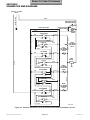
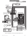
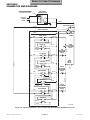
5.1 Electrical Schematics / Wiring Diagrams ..... 5-1
5.2 Hydraulic Flow Diagrams ............................. 5-5
SECTION IV MAINTENANCE/SERVICE
INSTRUCTIONS
4.1 Introduction ................................................. 4-1
4.2 Motor Cover Assembly Removal /
Installation ............................................... 4-1
4.3 Checking / Adding Oil To Motor Pump ........ 4-1
4.4 Up Functions Shuttle Valve Removal /
Installation ............................................... 4-2
4.5 Down Functions Shuttle Valve Removal /
Installation ............................................... 4-3
4.6 Anti-cavitation Solenoid Valve Removal /
Installation ............................................... 4-4
4.7 Up Functions Relief Valve Removal /
Installation ............................................... 4-5
4.8 Down Functions Relief Valve Removal /
Installation ............................................... 4-6
4.9 Motor Pump Assembly - Complete
Removal / Installation .............................. 4-7
4.10 Motor Pump Removal / Installation ............. 4-8
4.11 Motor Shaft Seal Removal / Installation ...... 4-9
4.12 Back Cylinder Removal / Installation ......... 4-11
4.13 Tilt Cylinder Removal / Installation ............ 4-13
4.14 Base Cylinder Removal / Installation ......... 4-15
4.15 Foot Cylinder Removal / Installation .......... 4-17
SECTION VI PARTS LIST
6.1 Introduction ................................................. 6-1
6.2 Description of Columns ............................... 6-1
6.3 Torque Specifications and Important
Assembly Notes ....................................... 6-1
Pictorial Index ............................................. 6-2
Pictorial Index ............................................. 6-3
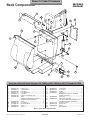
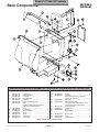
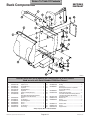
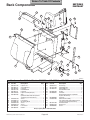
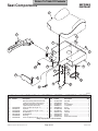
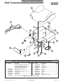
Back Components ...................................... 6-4.*
Back Components ...................................... 6-5.*
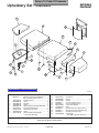
Upholstery Set - Standard ............................ 6-6
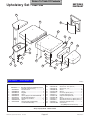
Upholstery Set - Narrow ............................... 6-7
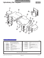
Upholstery Set - Styled ................................ 6-8
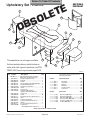
Upholstery Set - Thermoform ....................... 6-9
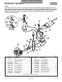
Hydraulic System ....................................... 6-10
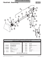
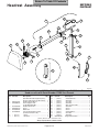
Headrest Assembly .................................. 6-11.*
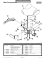
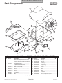
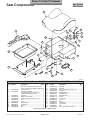
Seat Components .................................... 6-12.*
Seat Components .................................... 6-13.*
Stirrup Assembly ..................................... 6-14.*
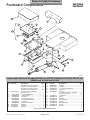
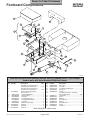
Footboard Components ............................ 6-15.*
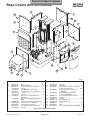
Base Covers And Enclosures .................... 6-16
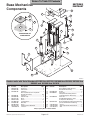
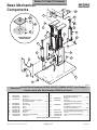
Base Mechanical Components ................. 6-17.*
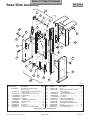
Base Slide Assembly ................................. 6-18
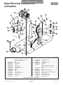
Base Electrical Components - Domestic .... 6-19
Base Electrical Components - Export ........ 6-20*
(*) Indicates that there has been a serial number break for the illustration
and that there are additional point page(s) following the original page.
© Midmark Corporation 1997 SF-1555 Rev. 11/02
Page i
Printed in U.S.A.
Return To Table Of Contents
TABLE OF CONTENTS - CONTINUED
Section/Paragraph
Page
Motor / Pump Components ........................ 6-21
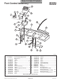
Foot Control Assembly ............................... 6-22
Section/Paragraph
Page
COMMENTS ............................................................ 7-1
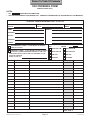
FAX ORDERING FORM .......................................... 7-2
(*) Indicates that there has been a serial number break for the illustration
and that there are additional point page(s) following the original page.
© Midmark Corporation 1997 SF-1555 Rev. 3/99
Page ii
Printed in U.S.A.
Return To Table Of Contents
IMPORTANT INSTRUCTIONS
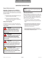
General Safety Instructions
NOTE
Safety First: The primary concern of Midmark
Corporation is that this table is maintained with the
safety of the patient and staff in mind. To assure that
services and repairs are completed safely and correctly,
proceed as follows:
(1) Read this entire manual before performing any
services or repairs on this table.
(2) Be sure you understand the instructions
contained in this manual before attempting to
service or repair this table.
Safety Alert Symbols
Throughout this manual are safety alert symbols that
call attention to particular procedures. These items are
used as follows:
DANGER
A DANGER is used for an imminently
hazardous operating procedure,
practice, or condition which, if not correctly
followed, will result in loss of life or serious
personal injury.
A NOTE is used to amplify an operating procedure,
practice or condition.
Warranty Instructions
Refer to the Midmark “Limited Warranty” printed in the
Installation and Operation Manual for warranty information. Failure to follow the guidelines listed below will
void the warranty and/or render the 319 Power Examination Table unsafe for operation.
• In the event of a malfunction, do not attempt to
operate the table until necessary repairs have been
made.
• Do not attempt to disassemble table, replace malfunctioning or damaged components, or perform
adjustments unless you are one of Midmark’s
authorized service technicians.
• Do not substitute parts of another manufacturer
when replacing inoperative or damaged components.
Use only Midmark replacement parts.
WARNING
A WARNING is used for a potentially
hazardous operating procedure,
practice, or condition which, if not correctly
followed, could result in loss of life or serious
personal injury.
CAUTION
A CAUTION is used for a potentially
hazardous operating procedure, practice,
or condition which, if not correctly followed, could
result in minor or moderate injury. It may also be
used to alert against unsafe practices.
EQUIPMENT ALERT
An EQUIPMENT ALERT is used for an
imminently or potentially hazardous
operating procedure, practice, or condition which, if
not correctly followed, will or could result in serious,
moderate, or minor damage to unit.
© Midmark Corporation 1997 SF-1555
Page iii
Printed in U.S.A.
Return To Table Of Contents
© Midmark Corporation 1997 SF-1555
Page iv
Printed in U.S.A.
Return To Table Of Contents
SECTION I
GENERAL INFORMATION
SECTION I
GENERAL INFORMATION
1.1 Scope of Manual
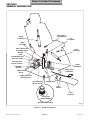
The major serviceable components of the table are the
motor pump, up functions relief valve (600 PSI), down
functions relief valve (400 PSI), up functions shuttle
valve, down functions shuttle valve, anti-cavitation
solenoid valve, capacitors, control panel with terminal
block, back cylinder, foot cylinder, tilt cylinder, base
cylinder, base slide assembly, chain assembly, pan
safety limit switch (optional on some tables), time delay
relay, foot switches, and isolation transformer (export
units only).
This manual contains detailed troubleshooting, scheduled maintenance, maintenance, and service instructions for 319 Power Examination Table. This manual is
intended to be used by Midmark’s authorized service
technicians.
1.2 How to Use Manual
A. Manual Use When Performing Scheduled Maintenance.
The Model 319 Power Examination Table series is
available in two different configurations which are
distinguished as follows:
(1) Perform inspections and services listed in
Scheduled Maintenance Chart (Refer to
para 3.1).
Model 319-003 115 VAC , w/o siderails and
w/o treatment pan.
Model 319-004 220 VAC , w/o siderails and
w/o treatment pan.
(2) If a component is discovered to be faulty or out
of adjustment, replace or adjust component in
accordance with maintenance/service instructions (Refer to para 4.1).
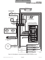
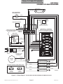
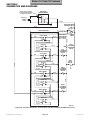
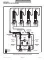
B. Theory of Operation (See Section IV, Figures 5-1
thru 5-4 for wiring diagrams and electrical schematics, and Figures 5-5 and 5-6 for hydraulic flow
diagrams.)
B. Manual Use When Table Is Malfunctioning And
Cause Is Unknown.
(1) Perform an operational test on table (Refer to
para 2.1).
On domestic units, 115 VAC is supplied directly to the
circuitry of the table. On export units, 220 VAC is
supplied to isolation transformer. The isolation transformer then supplies 115 VAC to the circuitry of the
table.
(2) Perform troubleshooting procedures listed in
Troubleshooting Guide (Refer to para 2.2).
(3) If a component is discovered to be faulty or out
of adjustment, replace or adjust component in
accordance with maintenance/service instructions (Refer to para 4.1).
C. Manual Use When Damaged Component Is Known.
(1) Replace or adjust component in accordance
with maintenance/service instructions (Refer to
para 4.1).
1.3 Description Of 319 Power Examination
Table
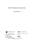
A. General Description (See Figure 1-1).
The 319 Power Examination Table is an examination
table designed specifically for performing general
medical examinations and procedures.
© Midmark Corporation 1997 SF-1555
When no functions are selected, 115 VAC is supplied to
terminals 1 and 2 of all foot switches. There is no path
to neutral, however, so no current flows and nothing
happens. When the operator selects one of the four up
functions (BACK UP, TABLE UP, FOOT UP, or TILT
UP) with the foot control, three paths to neutral are
created. Current flows from terminal 2 to terminal 4 of
switch and then across the motor pump winding T2 to
neutral, starting the motor pump pumping. Current also
flows from terminal 2 to terminal 4 of switch and then
across the coil of the anti-cavitation solenoid valve,
energizing the valve and causing it to open. Current
also flows from terminal 2 to terminal 3 of switch and
then across the coil of the cylinder solenoid valve and
the time delay relay, energizing the valve and causing it
to open. The time delay relay delays current flow
across the coil of the cylinder solenoid valve for 1/10 of
a second, causing it to energize 1/10 of a second after
Page 1-1
Printed in U.S.A.
Return To Table Of Contents
SECTION I
GENERAL INFORMATION
PAN SAFETY
LIMIT SWITCH
BACK
CYLINDER
TILT
CYLINDER
BASE
CYLINDER
ANTI-CAVITATION
SOLENOID VALVE
FOOT
CYLINDER
MOTOR
PUMP
DOWN FUNCTION
SHUTTLE VALVE
UP FUNCTION
SHUTTLE VALVE
CHAIN
ASSEMBLY
TERMINAL
BLOCK
BASE SLIDE
ASSEMBLY
TIME DELAY
RELAY
DOWN FUNCTION
RELIEF VALVE
UP FUNCTION
RELIEF VALVE
CAPACITORS
FOOT
SWITCH
FOOT
CONTROL
ISOLATION
TRANSFORMER
(EXPORT UNITS ONLY)
MA398400
Figure 1-1. Major Components
© Midmark Corporation 1997 SF-1555
Page 1-2
Printed in U.S.A.
Return To Table Of Contents
SECTION I
GENERAL INFORMATION
the motor pump and anti-cavitation solenoid valve have
energized. This allows the motor pump to run and oil
pressure to build first, so table top will not drift downward slightly before starting to rise. On tables that have
an optional treatment pan assembly, the foot function
also has a pan safety limit switch in its circuit. If the
treatment pan assembly is not pushed into its fully
stowed position, the pan safety limit switch will not be
tripped. If the pan safety limit switch is not tripped,
current flow is interrupted, keeping the cylinder solenoid
valve from energizing. This safety feature prevents the
table operator from accidentally colliding the foot section
into the treatment pan assembly.
When the motor pump starts pumping, suction is
created by the rotating pump gears, which allows oil to
defeat the reservoir check valve and flow into the pump
gears. The pump gears pressurize the oil which flows to
the up function shuttle valve. The check ball and
shuttle in the up function shuttle valve are pushed to the
open position by the oil, allowing oil to flow through the
shuttle valve by flowing around the check ball (with the
shuttle in the open position, oil is prevented from flowing
through the reservoir ports and returning to the reservoir). The oil then flows through the open cylinder
solenoid valve at the base of the selected cylinder,
extending the cylinder rod. When the cylinder rod
extends, oil is forced out of the rod end of the cylinder,
through the open anti-cavitation solenoid valve and to
the down function shuttle valve. The check ball and the
shuttle in the down function shuttle valve are pushed to
the closed position by the oil, which prevents oil from
flowing through the shuttle valve and into the motor
pump, but allows the oil to flow through the newly
uncovered reservoir ports into the reservoir. When the
cylinder rod reaches the end of its travel, the up function
relief valve opens when the pressure reaches 525 - 600
PSI (36.2 - 41.4 BARS) and allows the oil to return to
the reservoir. This prevents the motor pump from
developing too high of pressures and damaging the
hydraulic system components, hoses, or the motor
pump itself.
When the operator releases the pedal on the foot
control, the path to neutral is opened, causing the motor
pump to shut down and the anti-cavitation solenoid
valve and the cylinder solenoid valve to de-energize,
causing the valves to close.
When no functions are selected, 115 VAC is supplied to
terminals 1 and 2 of all foot switches. There is no path
© Midmark Corporation 1997 SF-1555
to neutral, however, so no current flows and nothing
happens. When the operator selects one of the four
down functions (BACK DOWN, TABLE DOWN, FOOT
DOWN, or TILT DOWN) with the foot control, two paths
to neutral are created. Current flows from terminal 2 to
terminal 4 of switch and then across the motor pump
winding T3 to neutral, starting the motor pump pumping.
Current also flows from terminal 2 to terminal 3 of switch
and then across the coil of the cylinder solenoid valve
and the time delay relay, energizing the valve and
causing it to open. The time delay relay delays current
flow across the coil of the cylinder solenoid valve for 1/
10 of a second, causing it to energize 1/10 of a second
after the motor pump and anti-cavitation solenoid valve
have energized. This allows the motor pump to run and
oil pressure to build before table is operated, so table
top will not cavitate. The foot function also has a pan
safety limit switch in its circuit. If the treatment pan
assembly is not pushed into its fully stowed position,
the pan safety limit switch will not be tripped. If the pan
safety limit switch is not tripped, current flow is interrupted, keeping the cylinder solenoid valve from energizing. This safety feature prevents the table operator from
accidentally colliding the foot section into the treatment
pan assembly.
When the motor pump starts pumping, suction is
created by the rotating pump gears, which allows oil to
defeat the reservoir check valve and flow into the pump
gears. The pump gears pressurize the oil which flows to
the down function shuttle valve. The check ball and
shuttle in the down function shuttle valve are pushed to
the open position by the oil, allowing oil to flow through
the shuttle valve by flowing around the check ball (with
the shuttle in the open position, oil is prevented from
flowing through the reservoir ports and returning to the
reservoir). The oil then flows through the open anticavitation solenoid valve and into the rod end of the
cylinder, causing the cylinder rod to retract. When the
cylinder rod retracts, oil is forced out of the base of the
cylinder, through the open cylinder solenoid valve to the
up function shuttle valve. The check ball and the
shuttle in the up function shuttle valve are pushed to the
closed position by the oil, which prevents oil from
flowing through the shuttle valve and into the motor
pump, but allows the oil to flow through the newly
uncovered reservoir ports into the reservoir. When the
cylinder rod reaches the end of its travel, the down
functions relief valve opens when the pressure reaches
250 - 325 PSI (17.2 - 22.4 BARS) and allows the oil to
Page 1-3
Printed in U.S.A.
Return To Table Of Contents
SECTION I
GENERAL INFORMATION
return to the reservoir. This prevents the motor pump
from developing too high of pressures and damaging the
hydraulic system components, hoses, or the motor
pump itself.
When the operator releases the pedal on the foot
control, the path to neutral is opened, causing the motor
pump to shut down and the cylinder solenoid valve to
de-energize, causing the valve to close.
The anti-cavitation solenoid valve is in the hydraulic
system to prevent oil from escaping out of the rod end
of a cylinder while the table is not being moved. Otherwise, a cylinder rod would be able to extend on its own if
upward pressure was placed on that function of the table
top by the doctor or patient.
The cylinder solenoid valves are in the hydraulic system
to prevent oil from escaping out of the base of the
cylinder assemblies. Otherwise, a cylinder assembly
could retract on its own, allowing the table top to drift.
Shipping Carton ...... 58 in. "L" x 31 in. "W" x 42 in. "H"
(147 cm x 79 cm x 107 cm)
Dimensions (See Figure 1-2):
Table Top Length .............................. 70 in. (177.8 cm)
Table Top Length (headrest extended) ............... 80 in.
(203.2 cm)
Table Top Width.................................. 27 in. (68.6 cm)
Overall Width ...................................... 27 in. (68.6 cm)
Table Positioning (Adjustable):
Standard Base Table Top Height .......... 26 in. to 42 in.
(66 cm to 107 cm)
Weight Capacity .................................. 325 lb (147.3 kg)
Oil Used In Hydraulic System ....................... light grade
medicinal mineral oil
Hydraulic System
Oil Capacity ..................... Approx. 2.5 quarts (2.4 liters)
Motor Pump Reservoir Capacity ......... 1 quart (.946 liter)
1.4 Standard Torque Specifications
The following standard torque specifications in Table
1-1 apply to the various hardware used on the units
unless otherwise listed elsewhere in service procedures
or parts illustrations:
Table 1-1. Torque Specifications
Hardware Size
Torque Values
#6 ........................... 11 to 21 inch / lbs. (1.2 to 2.3 N•M)
#8 ........................... 20 to 30 inch / lbs. (2.2 to 3.3 N•M)
#10.......................... 32 to 42 inch / lbs. (3.6 to 4.8 N•M)
1/4" ......................... 75 to 85 inch / lbs. (8.5 to 9.6 N•M)
5/16" .................... 18 to 22 foot / lbs. (24.4 to 29.8 N•M)
3/8" ...................... 31 to 35 foot / lbs. (42.0 to 47.5 N•M)
1/2" ...................... 50 to 60 foot / lbs. (67.8 to 81.4 N•M)
1.5 SPECIFICATIONS
Power Consumption:
115 VAC Unit ........................................... 960 WATTS,
8 amps @ 120 VAC
230 VAC Unit ........................................... 960 WATTS,
4 amps @ 240 VAC
Recommended Circuit:
A separate (dedicated) circuit is recommended for
this table. The table should not be connected to an
electrical circuit with other appliances or equipment
unless the circuit is rated for the additional load.
Up Function Relief Valve Setting............ Valve opens at
525 to 600 PSI
(36.2 to 41.4 BARS)
Factual data for the 319 Power Examination Table is
provided in Table 1-2. Also, see Figure 1-2.
Table 1-2. Specifications
Description
Electrical Requirements:
115 VAC Unit ............................ 110 - 120 VAC, 60 HZ,
12 amp, single phase
230 VAC Unit ..................... 220 - 240 VAC, 50 - 60 HZ,
12 amp, single phase
Data
Down Function Relief Valve Setting ....... Valve opens at
250 to 325 PSI
(17.2 to 22.4 BARS)
Weight:
Fixed Base
Without Shipping Carton ................. 390 lb (176.8 kg)
With Shipping Carton ...................... 455 lb (206.7 kg)
© Midmark Corporation 1997 SF-1555
Page 1-4
Printed in U.S.A.
Return To Table Of Contents
SECTION I
GENERAL INFORMATION
70" LONG (MIN.)
80" LONG (MAX.)
23"
WIDE
BASE
27"
WIDE
SEAT
A
21"
(MIN.)
B
45°
87°
90°
42"
(MAX.)
26"
(Min.)
MA398600
6'
CORD
31"
BASE
Figure 1-3. Model Number / Serial
Number Location
4'
CORD
MA398500
(2) Refer to the Parts List to determine the item
numbers of the parts, part numbers of the parts,
descriptions of the parts, and quantities of parts
needed and record this data (Refer to para 6.1).
Figure 1-2. Table Dimensions
1.6 Parts Replacement Ordering
If a part replacement is required, order the part directly
from the factory as follows:
NOTE
Ask the Purchasing Department of the company that
owns the table for this information. Otherwise, this
information may be obtained from the dealer that sold
the table.
NOTE
It is important that the entire Model and Serial
Number be presented when ordering parts, scheduling a service call, or seeking technical advice.
(3) Determine the installation date of the table and
record this data.
(1) Refer to Figure 1-3 to determine the location of
the model number (A) and serial number (B) of
the table and record this data.
Table 1-3. Special Tool List
Description of Special Tool
Manufacturer's
Name / Address / Phone
Manufacturer's
Part Number
Purpose of Special Tool
Multimeter
Commercially Available
Any Type
Used to perform continuity and voltage checks.
Torque Wrench
Commercially Available
Any Type
Used to tighten all hardware to torque values
specified.
© Midmark Corporation 1997 SF-1555
Page 1-5
Printed in U.S.A.
Return To Table Of Contents
SECTION I
GENERAL INFORMATION
(4) Call Midmark with the recorded information and
ask for the Medical Products Technical Services Department. See back cover of this
manual for the phone number or use the Fax
Order Form (See page 7-2 for Fax Order Form).
1.7 Special Tools
Table 1-3 lists all of the special tools needed to repair
the table, how to obtain the special tools, and the
purpose of each special tool.
© Midmark Corporation 1997 SF-1555
Page 1-6
Printed in U.S.A.
Return To Table Of Contents
SECTION II
TESTING AND TROUBLESHOOTING
SECTION II
TESTING AND TROUBLESHOOTING
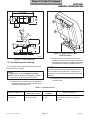
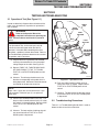
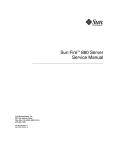
2.1 Operational Test (See Figure 2-1)
In order to effectively diagnose the malfunction of the
table, it may be necessary to perform an operational
test as follows:
BACK
SECTION
WARNING
TABLE
TOP
SEAT
SECTION
Refer to the Operator Manual for
complete instructions on operating the
table. Failure to do so could result in personal
injury.
FOOT
SECTION
NOTE
The Operational Test, for the most part, only describes what should happen when the table is
operated. If the table does something other than
described, a problem has been discovered. Refer to
the Troubleshooting Guide to determine the cause of
the problem and its correction.
PAN SLIDE
ASSEMBLY
(OPTIONAL
ON SOME
UNITS)
(1) Plug the table into a grounded, non-isolated,
correctly polarized outlet that has the proper
voltage output for the table. See Figure 2-1.
(2) Depress TABLE UP, TABLE DOWN, BACK
UP, BACK DOWN, TILT UP, TILT DOWN,
FOOT UP, and FOOT DOWN pedals on foot
control.
FOOT
CONTROL
MA403400
(3) Observe. The table top should move in the
direction corresponding to the pedal which is
being depressed. Movement should be steady
and should not be too slow or too fast.
Figure 2-1. Operational Test
(6) Push pan slide assembly inward until pan
safety limit switch is tripped. Depress either
FOOT UP or FOOT DOWN pedal on foot
control.
NOTE
Steps 4 thru 7 apply only to units which have a pan
slide assembly / treatment pan (it is an option on
some units).
(7) Observe. The foot section of table top should
move when FOOT UP or FOOT DOWN pedal
is depressed.
(4) Lower FOOT DOWN function all the way. Pull
the pan slide assembly outward until pan safety
limit switch is no longer tripped. Depress either
FOOT UP or FOOT DOWN pedal on foot
control.
2.2 Troubleshooting Procedures
Table 2-1 is a Troubleshooting Guide which is used to
determine the cause of the malfunction.
(5) Observe. The foot section of table top should
not move when either FOOT UP or FOOT
DOWN pedal is depressed.
© Midmark Corporation 1997 SF-1555
Page 2-1
Printed in U.S.A.
Return To Table Of Contents
SECTION II
TESTING AND TROUBLESHOOTING
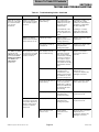
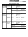
Table 2-1. Troubleshooting Guide
Problem
Table will not operate
when any of the eight
up or down functions
are selected.
Symptom
When a foot pedal is
depressed, motor pump
does not run and
solenoid cannot be
heard being energized
(audible click).
When a foot pedal is
depressed, motor pump
does not run, but
solenoid energizes
(audible click).
When a foot pedal is
depressed, motor pump
runs and solenoid can
be heard energizing.
© Midmark Corporation 1997 SF-1555 Rev. 12/02
Probable Cause
Check
Correction
Power cord is not plugged
into facility wall outlet or,
on expor t models, power
cord isn't plugged into
connector receptacle on
table.
Check to see if power
cord is plugged in.
Plug power cord into facility
wall outlet and/or connector
receptacle on table.
Facility circuit breaker
providing power to table is
tripped.
Check to see if facility
circuit breaker is tripped.
If circuit breaker is tripped,
correct the problem, then
reset circuit breaker.
Fuse(s) in AC connector
receptacle is blown (expor t
units only).
Perform continuity check
on fuses.
Replace fuse(s).
Wire connections loose.
Check all wiring
connections from power
cord to terminal block
and from foot control to
terminal block.
Clean dir ty connections.
Repair loose / damaged
connections.
Isolation transformer is
malfunctioning (expor t
units only).
Check input and output
voltage of isolation
transformer or replace
suspect isolation
transformer with known
working transformer.
If isolation transformer is
receiving proper input
voltage but is not supplying
115 VAC output, replace
isolation transformer.
Capacitor(s) is blown
(motor pump may be
humming).
Replace suspect
capacitor(s) with known
working capacitor(s).
Replace capacitor(s). Refer
to para 4.18.
Motor thermal overload
switch is activated
because motor pump
overheated.
Wait 15 to 20 minutes.
Allow motor pump to cool
and then try to operate
table. If motor pump does
not run, replace motor
pump. Refer to para 4.9 or
4.10.
Motor pump is burned out.
Replace suspect motor
pump.
Replace motor pump. Refer
to para 4.9 or 4.10.
Wire connections loose.
Check all wiring
connections from
terminal block to motor
pump.
Clean dir ty connections.
Repair loose / damaged
connections.
Hydraulic system is low on
mineral oil.
Check oil level in
reservoir.
If necessary, add oil to
reservoir. Refer to para 4.3.
Page 2-2
Printed in U.S.A.
Return To Table Of Contents
SECTION II
TESTING AND TROUBLESHOOTING
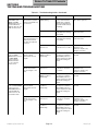
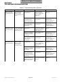
Table 2-1. Troubleshooting Guide - Continued
Problem
Table will not operate
when any of the eight
up or down functions
are selected Continued.
Symptom
When a foot pedal is
depressed, motor pump
runs, but table top does
not move.
When a foot pedal is
depressed, motor pump
hums, but does not run.
The TABLE UP, BACK
UP, TILT UP, and
FOOT UP functions do
not work, but TABLE
DOWN, BACK DOWN,
TILT DOWN, and
FOOT DOWN
functions do.
Motor pump runs when
an up function foot pedal
is depressed, but table
top does not move.
Motor pump does not
run when an up function
foot pedal is depressed,
but does when a down
function foot pedal is
depressed.
© Midmark Corporation 1997 SF-1555 Rev. 12/02
Probable Cause
Time delay relay is
malfunctioning.
Check
Correction
Use a jumper wire to
bypass time delay relay.
If table top moves now,
time delay relay is
malfunctioning.
A multimeter reading >1.2
amps indicates a faulty
cylinder has caused relay to
fail. Replace cylinder and
the time delay relay.
Put a multimeter in line
w/time delay relay and
run each cylinder one at
a time.
If reading is <1.2 amps,
replace time delay relay
only. Refer to para 4.16.
Capacitor(s) is blown.
Replace suspect
capacitor(s) with known
working capacitor(s).
Replace capacitor(s). Refer
to para 4.17.
Motor pump is locked up
or burned out.
Replace suspect motor
pump with known
working motor pump.
Replace motor pump. Refer
to para 4.9 or 4.10.
Anti-cavitation solenoid
valve is malfunctioning.
Check for slight
magnetism on bottom
side of anti-cavitation
solenoid valve, indicating
solenoid is not burned
out or replace suspect
anti-cavitation solenoid
valve with known working
anti-cavitation solenoid
valve.
Replace anti-cavitation
solenoid valve. Refer to
para 4.6.
Wire connections loose.
Check all wiring
connections from
terminal block to anticavitation solenoid valve.
Use multimeter to check
for proper voltage levels.
Clean any dir ty connections.
Tighten any loose
connections. Replace any
damaged connections.
Up function shuttle valve is
malfunctioning.
Check to see if check ball
is loose in up function
shuttle valve or adjacent
elbow (check ball should
be held in shuttle valve
by metal ring).
Replace up function shuttle
valve. Refer to para 4.4.
Motor pump is defective.
Replace suspect motor
pump with known
working motor pump.
Replace motor pump. Refer
to para 4.9 or 4.10.
Motor pump is defective.
Replace suspect motor
pump with known
working motor pump.
Replace motor pump. Refer
to para 4.9 or 4.10.
Wire connection in foot
control is loose.
Check all wiring
connections in foot
control.
Clean any dir ty connections.
Tighten any loose
connections. Replace any
damaged connections.
Page 2-3
Printed in U.S.A.
Return To Table Of Contents
SECTION II
TESTING AND TROUBLESHOOTING
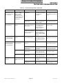
Table 2-1. Troubleshooting Guide - Continued
Problem
Symptom
The TABLE DOWN,
BACK DOWN, TILT
DOWN, and FOOT
DOWN functions do not
work, but TABLE UP,
BACK UP, TILT UP, and
FOOT UP functions do.
Motor pump runs when a
down function foot pedal
is depressed, but table top
does not move.
BACK UP function
works, but BACK DOWN
function does not or
BACK DOWN function
works but BACK UP
function does not. All
other functions work.
Check
Correction
Check to see if check ball
is loose in down function
shuttle valve or adjacent
elbow (check ball should
be held in shuttle valve by
metal ring).
Replace down function shuttle
valve. Refer to para 4.5.
Motor pump is defective.
Replace suspect motor
pump with known working
motor pump.
Replace motor pump. Refer
to para 4.9 or 4.10.
Motor pump is defective.
Replace suspect motor
pump with known working
motor pump.
Replace motor pump. Refer
to para 4.9 or 4.10.
Wire connection in foot
control is loose.
Check all wiring
connections in foot control.
Clean any dirty connections.
Tighten any loose
connections. Replace any
damaged connections.
Motor pump does not run
and base cylinder
solenoid valve does not
energize.
TABLE UP or TABLE
DOWN foot switch is
malfunctioning.
Perform a continuity check
on suspect foot switch in
ON and OFF positions or
replace suspect foot switch
with known working foot
switch.
Replace foot switch. Refer to
para 4.24.
Motor pump runs but base
cylinder solenoid valve
does not energize or vice
versa.
Wire connection to foot
switch is loose.
Check all wiring
connections on suspect
foot switch.
Clean any dirty connections.
Tighten any loose
connections. Replace any
damaged connections.
TABLE UP or TABLE
DOWN foot switch is
malfunctioning.
Perform a continuity check
on suspect foot switch in
ON and OFF positions or
replace suspect foot switch
with known working foot
switch.
Replace foot switch. Refer to
para 4.24.
Motor pump does not run
and back cylinder
solenoid valve does not
energize.
BACK UP or BACK DOWN
foot switch is
malfunctioning.
Perform a continuity check
on suspect foot switch in
ON and OFF positions or
replace suspect foot switch
with known working foot
switch.
Replace foot switch. Refer to
para 4.24.
Motor pump runs but back
cylinder solenoid valve
does not energize or vice
versa.
Wire connection to foot
switch is loose.
Check all wiring
connections on suspect
foot switch.
Clean any dirty connections.
Tighten any loose
connections. Replace any
damaged connections.
BACK UP or BACK DOWN
foot switch is
malfunctioning.
Perform a continuity check
on suspect foot switch in
ON and OFF positions or
replace suspect foot switch
with known working foot
switch.
Replace foot switch. Refer to
para 4.24.
Motor pump does not run
when a down function foot
pedal is depressed, but
runs when an up function
is pressed.
TABLE UP function
works, but TABLE
DOWN function does not
or TABLE DOWN
function works but
TABLE UP function
does not. All other
functions work.
Probable Cause
Down function shuttle valve
is malfunctioning.
© Midmark Corporation 1997 SF-1555
Page 2-4
Printed in U.S.A.
Return To Table Of Contents
SECTION II
TESTING AND TROUBLESHOOTING
Table 2-1. Troubleshooting Guide - Continued
Problem
TILT UP function works,
but TILT DOWN function
does not or TILT DOWN
function works but TILT
UP function does not.
All other functions work.
Symptom
Probable Cause
Check
Motor pump does not run
and tilt cylinder solenoid
valve does not energize.
TILT UP or TILT DOWN foot
switch is malfunctioning.
Perform a continuity check
on suspect foot switch in
ON and OFF positions or
replace suspect foot switch
with known working foot
switch.
Replace foot switch. Refer to
para 4.24.
Motor pump runs but tilt
cylinder solenoid valve
does not energize or vice
versa.
Wire connection to foot
switch is loose.
Check all wiring
connections on suspect
foot switch.
Clean any dirty connections.
Tighten any loose
connections. Replace any
damaged connections.
TILT UP or TILT DOWN foot
switch is malfunctioning.
Perform a continuity check
on suspect foot switch in
ON and OFF positions or
replace suspect foot switch
with known working foot
switch.
Replace foot switch. Refer to
para 4.24.
FOOT UP or FOOT DOWN
foot switch is
malfunctioning.
Perform a continuity check
on suspect foot switch in
ON and OFF positions or
replace suspect foot switch
with known working foot
switch.
Replace foot switch. Refer to
para 4.24.
Wire connection to foot
switch is loose.
Check all wiring
connections on suspect
foot switch.
Clean any dirty connections.
Tighten any loose
connections. Replace any
damaged connections.
FOOT UP or FOOT DOWN
foot switch is
malfunctioning.
Perform a continuity check
on suspect foot switch in
ON and OFF positions or
replace suspect foot switch
with known working foot
switch.
Replace foot switch. Refer to
para 4.24.
Base cylinder solenoid valve
is malfunctioning.
Check to see if base
cylinder solenoid valve
energizes (audible click)
when foot pedal is
depressed.
Replace base cylinder. Refer
to para 4.14.
White wire running from
terminal 3 of foot switch to
terminal block is broken or
disconnected.
Check continuity of wire
and connections.
Clean any dirty connections.
Tighten any loose
connections. Replace any
damaged connections.
Wire running from terminal
block to base cylinder
solenoid valve is broken or
disconnected.
Check continuity of wire
and connections.
Clean any dirty connections.
Tighten any loose
connections. Replace any
damaged connections.
FOOT UP function
Motor pump does not run
works, but FOOT DOWN and foot cylinder solenoid
function does not or
valve does not energize.
FOOT DOWN function
works but FOOT UP
function does not. All
other functions work.
Motor pump runs but foot
cylinder solenoid valve
does not energize or vice
versa.
TABLE UP and TABLE
DOWN functions do not
work. All other functions
work.
Motor pump runs when
TABLE UP or TABLE
DOWN foot pedal is
depressed, but table top
does not move.
© Midmark Corporation 1997 SF-1555
Page 2-5
Correction
Printed in U.S.A.
Return To Table Of Contents
SECTION II
TESTING AND TROUBLESHOOTING
Table 2-1. Troubleshooting Guide - Continued
Problem
Symptom
Probable Cause
BACK UP and BACK
DOWN functions do not
work. All other functions
work.
Motor pump runs when
BACK UP or BACK
DOWN foot pedal is
depressed, but table does
not move.
Back cylinder solenoid valve
is malfunctioning.
Check to see if back
cylinder solenoid valve
energizes (audible click)
when foot pedal is
depressed.
Replace back cylinder. Refer
to para 4.12.
White/black wire running
from terminal 3 of foot
switch to terminal block is
broken or disconnected.
Check continuity of wire
and connections.
Clean any dirty connections.
Tighten any loose
connections. Replace any
damaged connections.
Wire running from terminal
block to back cylinder
solenoid valve is broken or
disconnected.
Check continuity of wire
and connections.
Clean any dirty connections.
Tighten any loose
connections. Replace any
damaged connections.
Tilt cylinder solenoid valve is
malfunctioning.
Check to see if tilt cylinder
solenoid valve energizes
(audible click) when foot
pedal is depressed.
Replace tilt cylinder. Refer to
para 4.13.
Orange wire running from
terminal 3 of foot switch to
terminal block is broken or
disconnected.
Check continuity of wire
and connections.
Clean any dirty connections.
Tighten any loose
connections. Replace any
damaged connections.
Wire running from terminal
block to tilt cylinder solenoid
valve is broken or
disconnected.
Check continuity of wire
and connections.
Clean any dirty connections.
Tighten any loose
connections. Replace any
damaged connections.
Foot cylinder solenoid valve
is malfunctioning.
Check to see if foot
cylinder solenoid valve
energizes (audible click)
when foot pedal is
depressed.
Replace foot cylinder. Refer
to para 4.15.
Red/black wire running from
terminal 3 of foot switch to
terminal block is broken or
disconnected.
Check continuity of wire
and connections.
Clean any dirty connections.
Tighten any loose
connections. Replace any
damaged connections.
Wires running from terminal
block to pan safety limit
switch and foot cylinder
solenoid valve are broken or
disconnected.
Check continuity of wire
and connections.
Clean any dirty connections.
Tighten any loose
connections. Replace any
damaged connections.
Treatment pan assembly is
not pushed in all the way
(applies only to units with an
optional treatment plan).
Check that the treatment
pan assembly is pushed in
all the way.
Push treatment pan assembly
in all the way.
TILT UP and TILT
DOWN functions do not
work. All other functions
work.
FOOT UP and FOOT
DOWN functions do not
work. All other functions
work.
Motor pump runs when
TILT UP or TILT DOWN
foot pedal is depressed,
but table does not move.
Motor pump runs when
FOOT UP or FOOT
DOWN foot pedal is
depressed, but foot
section does not move.
© Midmark Corporation 1997 SF-1555
Page 2-6
Check
Correction
Printed in U.S.A.
Return To Table Of Contents
SECTION II
TESTING AND TROUBLESHOOTING
Table 2-1. Troubleshooting Guide - Continued
Problem
Symptom
Probable Cause
FOOT UP and FOOT
DOWN functions do not
work. All other functions
work - Continued.
Motor pump runs when
FOOT UP or FOOT
DOWN foot pedal is
depressed, but foot
section does not move Continued (applies only to
units with an optional
treatment pan).
Pan safety limit switch is out
of adjustment.
Check to see if pan safety
limit switch is being tripped
by treatment pan
assembly.
Adjust pan safety limit switch
so it is tripped when treatment
pan assembly is pushed in all
the way.
Pan safety limit switch is
malfunctioning.
Perform continuity check
on pan safety limit switch
(pan in = closed).
Replace pan safety limit
switch. Refer to para 4.18.
A cylinder solenoid valve is
stuck in open position or is
malfunctioning.
Try to flush foreign objects
out of cylinder solenoid
valve by running oil
through cylinder in both
directions ten times.
Replace malfunctioning
cylinder assembly.
A foot switch is
malfunctioning and holding
cylinder solenoid valve in
the open position.
Use multimeter to check for
voltage at terminal 3 of
suspect foot switch (no
voltage should be present
when foot switch is in OFF
position).
Replace foot switch. Refer to
para 4.24
Any of the four functions
drift by themselves.
Table functions properly
otherwise.
Check
Correction
Back section of table top
may be lifted by hand or
tilt function may drift by
itself.
Table functions properly
otherwise.
Anti-cavitation solenoid
valve is malfunctioning.
Replace suspect
anti-cavitation solenoid
valve with known working
anti-cavitation solenoid
valve.
Replace anti-cavitation
solenoid valve. Refer to para
4.6.
Table moves fine for
light patient, but will not
move or moves slowly
for very heavy patient.
Occurs for both the up
and down functions.
Hydraulic system is low on
mineral oil.
Check oil level in reservoir.
If necessary, add oil to
reservoir. Refer to para 4.3.
Up functions and down
functions relief valves are
malfunctioning.
Replace suspect relief
valves with known working
relief valves.
Replace up functions and
down functions relief valves.
Refer to paras 4.7 and 4.8.
Occurs for up functions
only.
Up functions relief valve is
malfunctioning.
Replace suspect up
functions relief valve with
known working relief valve.
Replace up functions relief
valve. Refer to para 4.7.
Occurs for down functions
only.
Down function relief valve is
malfunctioning.
Replace suspect down
functions relief valve with
known working relief valve.
Replace down functions relief
valve. Refer to para 4.8.
Chain assemblies are loose.
Check tension of chain
assemblies.
Adjust tension of chain
assemblies. Refer to para
4.19.
Base slide assembly is worn
or deformed.
Check condition of base
slide assembly.
Replace base slide assembly.
Refer to para 4.20.
Excessive sideways play Table is not stable and
of table top.
can be moved from side
to side.
© Midmark Corporation 1997 SF-1555
Page 2-7
Printed in U.S.A.
Return To Table Of Contents
SECTION II
TESTING AND TROUBLESHOOTING
© Midmark Corporation 1997 SF-1555
Page 2-8
Printed in U.S.A.
Return To Table Of Contents
SECTION III
SCHEDULED MAINTENANCE
SECTION III
SCHEDULED MAINTENANCE
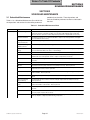
3.1 Scheduled Maintenance
Table 3-1 is a Scheduled Maintenance Chart which lists
the inspections and services that should be performed
periodically on the table. These inspections and
services should be performed as often as indicated in
the chart.
Table 3-1. Scheduled Maintenance Chart
Interval
Semi-annually
Inspection or Service
What to Do
Obvious damage
Visually check condition of table for obvious damage such as: cracks in components, missing
components, dents in components, leaking oil, or any other visible damage which would cause
table to be unsafe to operate or would compromise its performance. Repair table as necessary.
Fasteners/hardware
Check table for missing or loose fasteners/hardware. Replace any missing hardware and tighten
any loose hardware as necessary.
Warning and
instructional decals
Check for missing or illegible decals. Replace decals as necessary.
Pivot points/moving
parts/accessories
Lubricate all exposed pivot points, moving parts, and accessories with silicone based lubricant.
Hydraulic hoses and
fittings
Check all hydraulic hoses and fittings for leaks. Replace any components causing leaks. Replace
any hoses which have kinks, cuts, holes, or other damage.
Foot control
Check that foot control works correctly. Make sure foot pedals contact switch properly.
Hydraulic functions
Check that all four functions operate properly. If not, refer to the Troubleshooting Guide to
determine the cause of the problem. Clean or replace components as necessary.
Cylinders
Inspect all cylinders for signs of internal leaking or for weak operation. Replace cylinders as
necessary.
Drift in table
Check each cylinder to see if it drifts. Replace cylinder if necessary.
Oil level
Check oil level in motor pump. Add oil to motor pump if necessary. Refer to para 4.3.
Stirrup Assemblies
Check that stirrup assemblies lock into one of three positions. Check for wear. Replace
components as necessary. Refer to para 4.23.
Headrest Assembly
Check headrest for proper adjustment. If headrest does not have enough holding power, adjust
headrest handles. Refer to para 4.21.
Pan safety limit switch
Check that pan safety limit switch prevents foot function from moving when limit switch is not
tripped.
Excessive sideways
play of table top
Check that table top does not have excessive side play. Adjust chain assembly if necessary.
Refer to para 4.19.
Anti-cavitation solenoid
valve
Check to see if back section may be lifted by hand or if the tilt function drifts by itself. If so,
replace anti-cavitation solenoid valve. Refer to para 4.6.
Upholstery
Check all upholstery for rips, tears, or excessive wear. Replace cushions as necessary. Refer to
para 4.25.
Accessories
Check that all accessories have all of their components and that they function properly. If
necessary, repair or replace the accessory.
Operational Test
Perform an Operational Test to determine if the table is operating within its specifications (Refer to
para 2.1). Replace or adjust any malfunctioning components.
© Midmark Corporation 1997 SF-1555
Page 3-1
Printed in U.S.A.
Return To Table Of Contents
SECTION III
SCHEDULED MAINTENANCE
© Midmark Corporation 1997 SF-1555
Page 3-2
Printed in U.S.A.
Return To Table Of Contents
SECTION IV
MAINTENANCE / SERVICE
SECTION IV
MAINTENANCE / SERVICE INSTRUCTIONS
4.1 Introduction
A
WARNING
2
Refer to the Operator Manual for
complete instructions on operating the
table. Failure to do so could result in personal
injury.
3
NOTE
1
Perform an operational test on the table after the
repair is completed to confirm the repair was properly
made and that all malfunctions were repaired.
The following paragraphs contain removal, installation, repair, and adjustment procedures for the table.
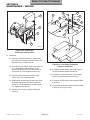
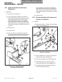
4.2 Motor Cover Assembly Removal /
Installation
MA394900
A. Removal
Figure 4-1. Motor Cover Assembly
Removal / Installation
WARNING
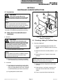
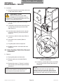
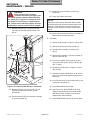
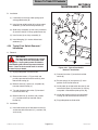
4.3 Checking / Adding Oil To Motor Pump
Always disconnect the power cord
from the outlet before removing any of the table's
covers/shrouds or making any repairs to prevent
the possibility of electrical shock. Failure to
comply with these instructions could result in
severe personal injury or death.
A. Checking / Adding Oil
(1) Move the BASE DOWN, BACK DOWN, TILT
DOWN, and FOOT DOWN functions all the way
down.
(1) Unplug table power cord from outlet.
NOTE
(2) Remove motor cover assembly (Refer to
4.2).
220 VAC (export units) contain an additional strap on
each side of the back outer shroud which helps
secure the back outer shroud.
(3) Remove filler cap (1, Figure 4-2) from motor
pump (2).
para
NOTE
(2) Remove six screws (1, Figure 4-1) and motor
cover assembly (2) from back outer shroud (3).
Newer models do not have screw (3) or oil level
check hole. Check oil level thru the fill port.
B. Installation
(1) Install motor cover assembly (2) against back
outer shroud (3) and secure with six screws (1),
making sure top edge of motor cover assembly
is inserted behind lip (A) of back outer shroud.
(4) Remove screw (3) and gasket (4) from motor
pump (2).
(5) Check oil level. If oil level in reservoir is not
even with oil level check hole, oil must be
added.
(2) Plug table power cord into outlet.
(6) Place a rag under oil level check hole (A).
© Midmark Corporation 1997 SF-1555 Rev. 6/02
Page 4-1
Printed in U.S.A.
Return To Table Of Contents
SECTION IV
MAINTENANCE / SERVICE
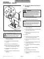
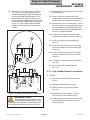
4.4 Up Functions Shuttle Valve Removal /
Installation
1
A. Removal
A
B
WARNING
Always disconnect the power cord
from the outlet before removing any of the table's
covers/shrouds or making any repairs to prevent
the possibility of electrical shock. Failure to
comply with these instructions could result in
severe personal injury or death.
3
4
2
(1) Unplug table power cord from outlet.
(2) Remove motor cover (Refer to para 4.2).
NOTE
The up functions shuttle valve is lower than the oil
level in the motor pump reservoir and oil will flow out
of the up functions shuttle valve once the hose
assembly is disconnected.
(3) Place drain pan (A) under up functions shuttle
valve (1, Figure 4-3).
(4) Disconnect hose assembly (2) from elbow (B) of
up functions shuttle valve (1).
MA395000
Figure 4-2. Checking / Adding Oil To Motor Pump
(5) Remove up functions shuttle valve (1) from
motor pump (3).
EQUIPMENT ALERT
B. Installation
Hydraulic system is designed for use with
light grade mineral oil only. Failure to
comply could result in hydraulic system failure.
(1) Coat two o-rings (C) on up functions shuttle
valve (1) with mineral oil or vaseline.
(7) Add oil to fill hole (B) until oil starts to run out of
oil level check hole (A).
(8) Install gasket (4) and screw (3) on motor
pump (2).
(2) Install up functions shuttle valve (1) in motor
pump (3).
(3) Connect hose assembly (2) to elbow (B) of up
functions shuttle valve (1).
(9) Install filler cap (1) on motor pump (2).
(4) If necessary, add oil to motor pump (Refer to
para 4.3).
(10) Move each function to its up and down limit
several times. Then repeat steps 1 thru 9.
(5) Install motor cover assembly (Refer to
para 4.2).
(11) Install motor cover assembly (Refer to
para 4.2).
(6) Plug table power cord into outlet.
(12) Dispose of used oil in accordance with local
regulations.
© Midmark Corporation 1997 SF-1555
Rev. 6/02
(7) Dispose of used oil in accordance with local
regulations.
Page 4-2
Printed in U.S.A.
Return To Table Of Contents
SECTION IV
MAINTENANCE / SERVICE
NOTE
The down functions shuttle valve is slightly lower
than the oil level in the motor pump reservoir and oil
will flow out of the down functions shuttle valve once
the hose assembly is disconnected.
C
B
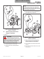
(3) Place rags or drain pan (A) under down functions shuttle valve (1, Figure 4-4).
3
C
4
1
2
A
MA395100
Figure 4-3. Up Functions Shuttle Valve
Removal / Installation
4.5
Down Functions Shuttle Valve
Removal / Installation
2
B
A. Removal
1
A
MA395200
WARNING
Figure 4-4. Down Functions Shuttle Valve
Removal / Installation
Always disconnect the power cord
from the outlet before removing any of
the table's covers/shrouds or making any repairs
to prevent the possibility of electrical shock.
Failure to comply with these instructions could
result in severe personal injury or death.
(4) Using a wrench to hold male connector (2)
stationary, loosen jam nut (B) of elbow (3).
Disconnect elbow from male connector.
(5) Remove elbow (3) from down function shuttle
valve (1).
(1) Unplug table power cord from outlet.
(2) Remove motor cover assembly (Refer to
para 4.2).
© Midmark Corporation 1997 SF-1555
3
(6) Remove down functions shuttle valve (1) from
motor pump (4).
Page 4-3
Printed in U.S.A.
Return To Table Of Contents
SECTION IV
MAINTENANCE / SERVICE
B. Installation
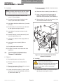
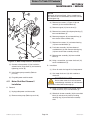
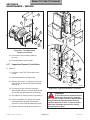
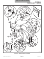
(5) Pull anti-cavitation solenoid valve wires (4) out
thru wire hole (B).
NOTE
(6) Disconnect hose assembly (6) from elbow (7).
The down functions shuttle valve is sent from factory
with an elbow installed on it. Remove it per step 1.
(1) Remove elbow from down function shuttle
valve (1). Discard elbow.
(7) Using a wrench to hold male connector (8)
stationary, loosen jam nut (C) of elbow (9).
Disconnect male connector (8) from elbow (9).
(2) Coat two o-rings on down functions shuttle
valve (1) with mineral oil or vaseline.
(8) Remove elbow (7) and male connector (8) from
anti-cavitation solenoid valve (10).
(3) Install down functions shuttle valve (1) in motor
pump (4).
(4) Coat threads of male connector (2) and elbow
(3) with pipe thread tape or sealant.
7
C
10
2
1
8
(5) Install elbow (3) on down functions shuttle
valve (1).
(6) Connect elbow (3) to male connector (2) and
secure by tightening jam nut.
(7) If necessary, add oil to motor pump (Refer to
para 4.3).
6
5
9
(8) Install motor cover assembly (Refer to
para 4.2).
(9) Plug table power cord into outlet.
(10) Dispose of used oil in accordance with local
regulations.
4.6
4
Anti-Cavitation Solenoid Valve
Removal / Installation
B
A
3
MA395300
Figure 4-5. Anti-cavitation Solenoid Valve
Removal / Installation
A. Removal
B. Installation
(1) Unplug table power cord from outlet.
EQUIPMENT ALERT
(2) Remove motor cover assembly (Refer to
para 4.2).
(3) Remove two screws (1, Figure 4-5) and control
cover (2) from control panel (3).
(4) Loosen two terminal screws (A); then tag and
disconnect anti-cavitation solenoid valve wires
(4) from terminal block (5).
© Midmark Corporation 1997 SF-1555
Do not coat last two threads of
elbow and male connector with teflon tape
or sealant. Otherwise, little particles of the tape /
sealant can break loose and can contaminate
hydraulic system.
(1) Coat threads of elbow (7) and male connector
(8) with pipe thread tape or sealant.
Page 4-4
Printed in U.S.A.
Return To Table Of Contents
SECTION IV
MAINTENANCE / SERVICE
(2) Install elbow (7) and male connector (8) on anticavitation solenoid valve (10).
5
(3) Connect hose assembly (6) to elbow (7).
6
(4) Coat threads of male connector (8) with pipe
thread tape or sealant.
4
(5) Connect elbow (9) to male connector (8) and
secure by tightening jam nut (C).
3
(6) Feed two anti-cavitation solenoid valve wires
(4) thru wire hole (B).
(7) Connect two anti-cavitation solenoid valve
wires (4) to terminal block (5) and secure by
tightening two terminal screws (A).
(8) Install control cover (2) on control panel (3) and
secure with two screws (1).
(9) Install motor cover assembly (Refer to
para 4.2).
2
(10) Plug table power cord into outlet.
1
8
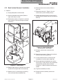
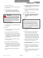
4.7 Up Functions Relief Valve Removal /
Installation
A
A. Removal
7
(1) If possible, raise TABLE UP function all the
way up.
(2) Unplug table power cord from outlet.
B
(3) Remove motor cover assembly (Refer to
para 4.2).
MA395400
(4) Remove four screws (1, Figure 4-6) and back
outer shroud (2) from left and right hand outer
shrouds (3).
Figure 4-6. Up Functions Relief Valve
Removal / Installation
NOTE
NOTE
The back inner shroud must be removed if it will
obstruct removal of up functions relief valve.
(5) If necessary, remove eight screws (4) and back
inner shroud (5) from left and right hand inner
shrouds (6).
© Midmark Corporation 1997 SF-1555
Page 4-5
Oil will flow out of relief valve port when up functions
relief valve is removed. Either have the new up
functions relief valve ready to install or place a drain
pan under relief valve port to catch oil.
(6) Remove up functions relief valve (7) from motor
pump (8).
Printed in U.S.A.
Return To Table Of Contents
SECTION IV
MAINTENANCE / SERVICE
B. Installation
5
(1) Coat two o-rings (A) on up functions relief valve
(7) with mineral oil or vaseline.
6
EQUIPMENT ALERT
Make sure relief valve (7) has "600"
stamped on its hex head (B); it must not
be stamped "L2". Failure to install proper relief valve
will result in faulty table performance.
4
3
(2) Install up functions relief valve (7) in motor
pump (8).
(3) If removed, install back inner shroud (5) on left
and right inner shrouds (6) and secure with
eight screws (4).
(4) Install back outer shroud (2) on left and right
hand outer shrouds (3) and secure with four
screws (1).
(5) If necessary, add oil to motor pump (Refer to
para 4.3).
2
1
(6) Install motor cover assembly (Refer to
para 4.2).
8
A
(7) Plug table power cord into receptacle.
7
(8) Dispose of used oil in accordance with local
regulations.
4.8 Down Functions Relief Valve Removal
/ Installation
B
A. Removal
MA395500
(1) Unplug table power cord from outlet.
Figure 4-7. Down Functions Relief Valve
Removal / Installation
(2) Remove motor cover assembly (Refer to
para 4.2).
(4) If necessary, remove eight screws (4) and back
inner shroud (5) from left and right hand inner
shrouds (6).
(3) Remove four screws (1, Figure 4-7) and back
outer shroud (2) from left and right hand outer
shrouds (3).
NOTE
NOTE
Oil will flow out of relief valve port when down
functions relief valve is removed. Either have the
new down functions relief valve ready to install or
place a drain pan under relief valve port to catch oil.
The back inner shroud must be removed if it will
obstruct removal of up functions relief valve.
© Midmark Corporation 1997 SF-1555
Page 4-6
Printed in U.S.A.
Return To Table Of Contents
SECTION IV
MAINTENANCE / SERVICE
(5) If necessary, add oil to motor pump (Refer to
para 4.3).
(5) Remove down functions relief valve (7) from
motor pump (8).
(6) Install motor cover assembly (Refer to
para 4.2).
B. Installation
(1) Coat two o-rings (A) on down functions relief
valve (7) with mineral oil or vaseline.
(7) Plug table power cord into receptacle.
EQUIPMENT ALERT
Make sure relief valve (7) has "L2"
stamped on its hex head (B); it must not
be stamped "600". Failure to install proper relief
valve will result in faulty table performance.
(2) Install down functions relief valve (7) in motor
pump (8).
(8) Dispose of used oil in accordance with local
regulations.
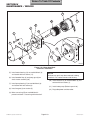
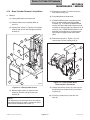
4.9 Motor Pump Assembly - Complete
Removal / Installation
A. Removal
(1) Unplug table power cord from outlet.
(3) If removed, install back inner shroud (5) on left
and right inner shrouds (6) and secure with
eight screws (4).
(2) Remove motor cover assembly (Refer to
para 4.2).
(4) Install back outer shroud (2) on left and right
hand outer shrouds (3) and secure with four
screws (1).
(3) Remove four screws (1, Figure 4-8) and back
outer shroud (2) from left and right hand outer
shrouds (3).
3
5
16
10
4
6
13
2
11
1
8
12
14
15
A
B
7
9
MA395600
Figure 4-8. Motor Pump Assembly - Complete Removal / Installation
© Midmark Corporation 1997 SF-1555
Page 4-7
Printed in U.S.A.
Return To Table Of Contents
SECTION IV
MAINTENANCE / SERVICE
(4) Remove two screws (4) and control cover (5)
from control panel (6).
(8) Install control cover (5) on control panel (6) and
secure with two screws (4).
(5) Loosen three terminal screws; then tag and
disconnect three motor pump wires (7) from
terminal block (8).
(9) Install back outer shroud (2) on left and right
hand outer shrouds (3) and secure with four
screws (1).
(6) Pull motor pump wires (7) out thru wire hole.
(10) Add oil to motor pump (Refer to para 4.3).
(7) Loosen two terminal screws; then tag and
disconnect anti-cavitation solenoid valve wires
(9) from terminal block (8).
(11) Install motor cover assembly (Refer to
para 4.2).
(12) Plug table power cord into outlet.
(8) Pull anti-cavitation solenoid valve wires (9) out
thru wire hole.
(13) Dispose of used oil in accordance with local
regulations.
(9) Remove four nuts (10) from four motor
mounts (11).
4.10
(10) Disconnect hose assembly (12) from male
elbow (13).
Motor Pump Removal / Installation
A. Removal
(1) Unplug table power cord from outlet.
(11) Place a drain pan under elbow (14).
(2) Remove motor pump assembly - Complete
(Refer to para 4.9).
(12) Disconnect hose assembly (15) from elbow
(14). Allow oil to drain into drain pan.
(3) Remove filler cap (A) and drain any remaining
oil into drain pan (See Figure 4-9).
(13) Remove motor pump assembly (16) from four
motor mounts (11).
(4) Using a wrench to hold male connector (1,
Figure 4-9) stationary, loosen jam nut (B) of
elbow (2). Disconnect male connector/anticavitation solenoid valve (C) from elbow.
B. Installation
(1) Install motor pump assembly (16) on four motor
mounts (11) and secure with four nuts (10).
(5) Remove down functions shuttle valve (3) and
up functions shuttle valve (4) from motor
pump (5).
(2) Connect hose assembly (15) to elbow (14).
(3) Connect hose assembly (12) to male elbow (13).
(6) Remove two screws (6), lockwashers (7), and
motor base (8) from motor pump (5).
(4) Feed two anti-cavitation solenoid valve wires
(9) thru wire hole.
B. Installation
(5) Connect two anti-cavitation solenoid valve
wires (9) to terminal block (8) and secure by
tightening two terminal screws.
(1) Install motor base (8) on motor pump (5) and
secure with two lockwashers (7) and
screws (6).
(6) Feed three motor pump wires (7) thru wire hole.
(2) Install up functions shuttle valve (4) and down
functions shuttle valve (3) on motor pump (5).
(7) Connect three motor pump wires (7) to terminal
block (8) and secure by tightening three
terminal screws.
© Midmark Corporation 1997 SF-1555
Page 4-8
(3) Coat threads of male connector (1) with pipe
thread tape or sealant.
Printed in U.S.A.
Return To Table Of Contents
SECTION IV
MAINTENANCE / SERVICE
NOTE
A
Reservoir will come off hard. Use a screwdriver to
pry reservoir off of manifold block, but make sure not
to damage o-ring.
5
C
(3) Remove four screws (1, Figure 4-10) and
reservoir (2) from manifold block (3).
2
(4) Remove magnet (4) from strainer (5).
(5) Remove four screws (6) and pump housing (7)
from manifold block (3).
1
3
B
(6) Remove pump gear (8) and woodruff key (9)
from shaft of rotor assembly (10).
4
(7) Remove four screws (11) and motor housing
(12) from manifold block (3).
8
(8) Push rotor assembly (10) inward toward
manifold block (3); then remove retaining ring
(13) from end of rotor assembly shaft (A).
7
6
(9) Remove rotor assembly (10) from manifold
block (3).
MA395700
(10) Using a screwdriver, pry motor shaft seal (14)
out of manifold block (3).
Figure 4-9. Motor Pump Removal / Installation
(4) Connect male connector (1)/anti-cavitation
solenoid valve (C) to elbow (2) and secure by
tightening jam nut (B).
B. Installation
(1) Clean all metal shavings off of all components.
(5) Install motor pump assembly (Refer to
para 4.9).
(2) Coat motor shaft seal (14) with vaseline or
mineral oil.
(6) Plug table power cord into outlet.
4.11
EQUIPMENT ALERT
Do not allow motor shaft seal to become
cocked during installation or it will become
impossible to install without damaging it.
Motor Shaft Seal Removal /
Installation
A. Removal
(3) Using a hammer and 3/4 inch socket, install
motor shaft seal (14) in manifold block (3).
(1) Unplug table power cord from outlet.
(4) Slide shaft of rotor assembly (10) thru manifold
block (3) and secure in place by installing
retaining ring (13) on end of rotor assembly
shaft.
(2) Remove motor pump (Refer to para 4.10).
© Midmark Corporation 1997 SF-1555
Page 4-9
Printed in U.S.A.
Return To Table Of Contents
SECTION IV
MAINTENANCE / SERVICE
12
11
10
B
3
14
6
2
A
4
13
8
7
9
5
1
MA395800
Figure 4-10. Motor Shaft Seal
Removal / Installation
(5) Install motor housing (12) on manifold block (3)
and secure with four screws (11).
(6) Install woodruff key (9) and pump gear (8) on
shaft of rotor assembly (10).
NOTE
Strainer may get in way when reservoir is being
installed. If so, rotate strainer out of the way.
(10) Install reservoir (2) on manifold block (3) and
secure with four screws (1).
(7) Install pump housing (7) on manifold block (3)
and secure with four screws (6).
(11) Install motor pump (Refer to para 4.10).
(8) Install magnet (4) on strainer (5).
(12) Plug table power cord into outlet.
(9) Make sure o-ring (B) on manifold block is
present and clean. Coat o-ring with mineral oil.
© Midmark Corporation 1997 SF-1555
Page 4-10
Printed in U.S.A.
Return To Table Of Contents
SECTION IV
MAINTENANCE / SERVICE
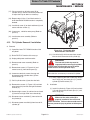
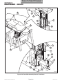
4.12
Back Cylinder Removal / Installation
(6) Remove motor cover assembly (Refer to
para 4.2).
A. Removal
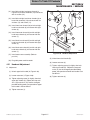
(7) Remove two screws (1, Figure 4-12) and
control cover (2) from control panel (3).
(1) Unplug table power cord from outlet.
(8) Loosen two terminal screws (a); then tag and
disconnect back cylinder wires (4) from terminal
block (5).
(2) Remove upholstered seat section (Refer to
steps 6 thru 8 of para 4.25).
(3) Remove four screws (1, Figure 4-11) and front
outer shroud (2) from left and right hand outer
shrouds (3).
1
5
6
2
3
3
5
B
4
A
1
2
7
4
MA396000
Figure 4-12. Back Cylinder Wires
Disconnection / Connection
9
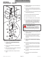
(9) Pull back cylinder wires (4) out thru wire
hole (B).
(10) Remove four screws (1, Figure 4-13) and back
cover (2) from back weldment (3).
8
(11) Cut two cable ties which are securing hose
assemblies (4 and 5) to back cylinder (6).
MA395900
Figure 4-11. Table Access
(12) While supporting back weldment (3), remove
four E-rings (7), two clevis pins (8), and partially
separate back cylinder (6) from cylinder
brackets (9). Fold back section over onto seat
section.
(4) Remove eight screws (4) and front inner shroud
(5) from left and right hand inner shrouds (6).
(13) Tag hose assemblies (4 and 5).
(5) Remove screw (7) and wire clip (8) securing
wires and hoses to base weldment (9).
(14) Disconnect hose assembly (4) from back
cylinder (6).
© Midmark Corporation 1997 SF-1555
Page 4-11
Printed in U.S.A.
Return To Table Of Contents
SECTION IV
MAINTENANCE / SERVICE
(15) Disconnect hose assembly (5) from back
cylinder (6).
(4) Secure hose assemblies (4 and 5) to back
cylinder (6) with two cable ties.
(16) Cut necessary cable ties and remove back
cylinder (6) from table.
(5) Route back cylinder wires (4, Figure 4-12) thru
table.
(6) Feed back cylinder wires (4) thru wire hole (B).
(7) Connect two back cylinder wires (4) to terminal
block (5) and secure by tightening two terminal
screws (A).
3
2
8
7
(8) Install control cover (2) on control panel (3) and
secure with two screws (1).
7
(9) Secure wires and hoses to base weldment (9,
Figure 4-11) with wire clip (8) and screw (7).
Install any cable ties removed during removal.
9
A
4
(10) Install front inner shroud (5) on left and right
hand outer shrouds (6) and secure with eight
screws (4).
6
1
5
8
B
(11) Install front outer shroud (2) on left and right
hand inner shrouds (3) and secure with four
screws (1).
7
(12) Install upholstered seat section (Refer to step 6
of para 4.25).
C
(13) Plug table power cord into outlet.
MA396100
(14) Lower BACK DOWN function all the way down.
Figure 4-13. Back Cylinder Removal / Installation
EQUIPMENT ALERT
B. Installation
NOTE
No sealant is required when connecting hose assemblies. The back cylinder has an o-ring in each port
which seals the hose assemblies.
Tilt down function must be completely
lowered for following step. Failure to do
so will result in incorrect adjustment.
(15) If back section is not level with floor when the
BACK DOWN function is completely lowered,
perform steps 16 thru 18. If back section is
level when the BACK DOWN function is
completely lowered, go to step 19.
(1) Connect hose assembly (5, Figure 4-13) to
back cylinder (6).
(2) Connect hose assembly (4) to back cylinder (6).
EQUIPMENT ALERT
(3) Install back cylinder (6) on cylinder brackets (9)
and secure with two clevis pins (8) through
clevis (A) with four E-rings (7).
The cylinder rod must be partially ex tended before performing step 17. If the
cylinder rod is fully extended or retracted when step
17 is being performed, damage to seals will occurr.
(16) Raise BACK UP function up until cylinder rod is
extended halfway.
© Midmark Corporation 1997 SF-1555
Page 4-12
Printed in U.S.A.
Return To Table Of Contents
SECTION IV
MAINTENANCE / SERVICE
(17) Place a wrench on adjusting seats (B) of
cylinder rod (C) and use it to rotate cylinder rod
to adjust clevis up or down as necessary.
2
(18) Repeat steps 14 thru 17 until back section is
level when BACK DOWN function is completely
lowered.
1
(19) Install back cover (2) on back weldment (3) and
secure with four screws (1).
3
5
(20) If necessary, add oil to motor pump (Refer to
para 4.3).
B
A
(21) Install motor cover assembly (Refer to
para 4.2).
4.13
Tilt Cylinder Removal / Installation
4
A. Removal
(1) If possible, lower TILT DOWN function all the
way down.
Figure 4-14. Tilt Cylinder Wire
Disconnection / Connection
(12) Cut cable tie (A) which secures hose assemblies and wire harnesses to tilt cylinder (8).
(2) Raise FOOT UP function all the way up.
(3) Unplug table power cord from outlet.
WARNING
The foot end of table top must be
supported while removing tilt cylinder.
Failure to do will allow table top to fall which
could result in serious personal injury.
(4) Remove motor cover assembly (Refer to
para 4.2).
(5) Remove two screws (1, Figure 4-14) and
control cover (2) from control panel (3).
NOTE
(6) Loosen two terminal screws; then tag and
disconnect two tilt cylinder wires (4) from
terminal block (5).
Cut cable ties as necessary to remove tilt cylinder.
(13) While supporting foot end of table top, remove
four E-rings (10), two clevis pins (11), and tilt
cylinder (8) from brackets (12).
(7) Pull tilt cylinder wires (4) out thru wire hole.
(8) Remove four screws (1, Figure 4-15) and front
outer shroud (2) from left and right hand outer
shrouds (3).
B. Installation
(1) Install tilt cylinder (8, Figure 4-15) on brackets
(12) and secure with two clevis pins (11) and
four E-rings (10).
(9) Remove eight screws (4) and front inner shroud
(5) from left and right hand inner shrouds (6).
(10) Disconnect return manifold (7) from rod end of
tilt cylinder (8).
(11) Disconnect power manifold (9) from base of tilt
cylinder (8).
© Midmark Corporation 1997 SF-1555
MA396200
WARNING
Make sure the safety cable (B) is
properly installed on the return and
power manifolds. Failure to do so could result in
serious personal injury to patient or table operator.
Page 4-13
Printed in U.S.A.
Return To Table Of Contents
SECTION IV
MAINTENANCE / SERVICE
(6) Feed tilt cylinder wires (4) thru wire hole (B) in
control panel (3).
5
6
6
(7) Connect two tilt cylinder wires (4) to terminal
block (5) and secure by tightening two terminal
screws (A).
(8) Install control cover (2) on control panel (3) and
secure with two screws (1).
3
4
(9) Install any cable ties which were removed.
(10) Plug table power cord into outlet.
3
1
(11) Lower TILT DOWN function all the way down.
2
(12) If seat section is not level with floor when the
TILT DOWN function is completely lowered,
perform steps 13 thru 15. If seat section is
level when the TILT DOWN function is completely lowered, go to step 16.
12
E
10
D
EQUIPMENT ALERT
11
7
The cylinder rod (C) must be partially
extended before performing step 14. If
the cylinder rod is fully extended or retracted when
step 14 is being performed, damage to seals will
occurr.
10
C
8
A
B
(13) Raise TILT UP function up until cylinder rod is
extended halfway.
10
11
9
12
(14) Place a wrench on adjusting seats D, Figure 415) of cylinder rod (C) and use it to rotate
cylinder rod to adjust clevis (E) up or down as
necessary.
10
MA393600
Figure 4-15. Tilt Cylinder Removal / Installation
(2) Connect power manifold (9) to base of tilt
cylinder (8), making sure safety cable (B) is
properly installed.
(16) Install front inner shroud (5) on left and right
hand inner shrouds (6) and secure with eight
screws (4).
(3) Connect return manifold (7) to rod end of tilt
cylinder (8).
(4) Secure wire harnesses and hose assemblies to
tilt cylinder (8) with a cable tie.
(5) Route tilt cylinder wires (4, Figure 4-14) thru
table.
© Midmark Corporation 1997 SF-1555
(15) Repeat steps 11 thru 15 until seat section is
level when TILT DOWN function is completely
lowered.
(17) Install front outer shroud (2) on left and right
hand outer shrouds (3) and secure with four
screws (1).
(18) If necessary, add oil to motor pump (Refer to
para 4.3).
(19) Install motor cover assembly (Refer to
para 4.2).
Page 4-14
Printed in U.S.A.
Return To Table Of Contents
SECTION IV
MAINTENANCE / SERVICE
4.14
Base Cylinder Removal / Installation
(5) Remove four screws (7) and brace (8) from
base slide assembly (9).
A. Removal
(6) Plug table power cord into outlet.
(1) Unplug table power cord from outlet.
(2) Remove motor cover assembly (Refer to
para 4.2).
(3) Remove four screws (1, Figure 4-16) and back
outer shroud (2) from left and right hand outer
shrouds (3).
(8) Remove two screws (1, Figure 4-17) and
control cover (2) from control panel (3).
6
5
(7) If BASE DOWN function is operable, place a
block (A) under middle slide of base slide
assembly (9). Then lower the BASE DOWN
function until the middle slide of the base slide
assembly is resting on block and pressure is off
clevis pin (10). If BASE DOWN function is not
operable, move table top to a horizontal position and place supports under each end of
table.
3
10
2
4
1
8
9
7
3
5
B
A
A
2
1
4
MA396400
Figure 4-16. Base Cylinder Access
MA396500
Figure 4-17. Base Cylinder Wires
Disconnection / Connection
(9) Loosen two terminal screws (A); then tag and
disconnect base cylinder wires (4) from terminal block (5).
(4) Remove eight screws (4) and back inner
shroud (5) from left and right hand inner
shrouds (6).
(10) Pull base cylinder wires (4) out thru wire
hole (B).
NOTE
The motor pump and control panel can be carefully
pushed out of the way to allow a socket and ratchet
to be used on the bottom two screws (7).
© Midmark Corporation 1997 SF-1555
Page 4-15
Printed in U.S.A.
Return To Table Of Contents
SECTION IV
MAINTENANCE / SERVICE
(14) Disconnect hose assembly (7) from base
cylinder (3).
DANGER
Make sure table top is properly
secured from lowering or tipping over
when base cylinder is disconnected from table
top. Clevis pin (2, Figure 4-18) should not have
any weight on it if table top is supported properly. Failure to have table top properly secured
could result in serious personal injury or death.
(15) Place rags under base tee (8).
NOTE
When base tee is disconnected from base cylinder,
oil will be free to flow out of the motor pump thru the
base tee. Either be ready to install the new base
cylinder or have drain pan and rags ready to catch
the oil.
(11) Remove hitch pin clip (1, Figure 4-18) and
clevis pin (2) from rod end (A) of base cylinder (3).
(16) Disconnect base tee (8) from base cylinder (3).
Remove base cylinder from table.
B. Installation
6
(1) Position base cylinder (3, Figure 4-18) on table.
2
(2) Connect base tee (8) to base cylinder (3).
(3) Connect hose assembly (7) to base cylinder (3).
A
7
(4) Secure hose assembly (7) to base cylinder (3)
with two cable ties (B).
1
(5) Install base cylinder (3) on brackets (6) and
secure with clevis pins (2 and 5) and hitch pin
clips (1 and 4).
3
B
(6) Feed base cylinder wires (4, Figure 4-17) thru
wire hole (B).
6
8
5
(7) Connect two base cylinder wires (4) to terminal
block (5) and secure by tightening two terminal
screws (A).
4
MA396600
Figure 4-18. Base Cylinder Removal / Installation
(12) Remove hitch pin clip (4), clevis pin (5), and
partially separate base cylinder (3) from
brackets (6).
(13) Cut two cable ties (B) securing hose assembly
(7) to base cylinder (3).
© Midmark Corporation 1997 SF-1555
Page 4-16
(8) Install control cover (2) on control panel (3) and
secure with two screws (1).
(9) Plug table power cord into outlet.
(10) See Figure 4-16. Raise BASE UP function
slightly and remove block from under middle
slide of base slide assembly (9) or remove
supports from under table top.
(11) Lower BASE DOWN function all the way down.
Printed in U.S.A.
Return To Table Of Contents
SECTION IV
MAINTENANCE / SERVICE
(12) See Figure 4-19. If there is not a 1/16 to 1/8
inch (1.6 to 3.2 mm) gap (A) between inner
member weldment (B) and top of middle slide
(C) when the BASE DOWN function is completely lowered (it is especially important that
the inner member weldment does not come into
contact with top of middle slide), perform steps
13 thru 15. If gap is correct when the BASE
DOWN function is completely lowered, go to
step 16.
(13) Raise BASE UP function up until cylinder rod is
extended halfway.
(14) Place a wrench on adjusting seats (D) of
cylinder rod (E) and use it to rotate cylinder rod
to adjust clevis (F) up or down as necessary.
(15) Repeat steps 11 thru 15 until there is a 1/16 to
1/8 inch (1.6 to 3.2 mm) gap (A) between inner
member weldment (B) and middle slide (C) of
base slide assembly when the BASE DOWN
function is completely lowered.
(16) Install brace (8, Figure 4-16) on base slide
assembly (9) and secure with four screws (7).
B
(17) Install any cable ties (B) removed during
removal.
A
(18) Install back inner shroud (5) on left and right
hand inner shrouds (6) and secure with eight
screws (4).
(19) Install back outer shroud (2) on left and right
hand outer shrouds (3) and secure with four
screws (1).
C
(20) If necessary, add oil to motor pump (Refer to
para 4.3).
1
(21) Install motor cover assembly (Refer to
para 4.2).
F
4.15
Foot Cylinder Removal / Installation
A. Removal
(1) If possible, raise FOOT UP function all the
way up.
E
(2) Unplug table power cord from outlet.
D
MA396700
(4) Remove two screws (1, Figure 4-20) and
control cover (2) from control panel (3).
Figure 4-19. Base Cylinder Clevis Adjustment
EQUIPMENT ALERT
(5) Loosen two terminal screws (A); then tag and
disconnect two foot cylinder wires (4) from
terminal block (5).
The cylinder rod (E) must be partially ex
-tended before performing step 14. If the
cylinder rod is fully extended or retracted when step
14 is being performed, damage to seals will occurr.
© Midmark Corporation 1997 SF-1555
(3) Remove motor cover assembly (Refer to
para 4.2).
Page 4-17
Printed in U.S.A.
Return To Table Of Contents
SECTION IV
MAINTENANCE / SERVICE
2
5
6
1
3
3
4
5
B
1
A
4
2
MA396900
MA396800
Figure 4-20. Foot Cylinder Wire
Disconnection / Connection
Figure 4-21. Shrouds Removal / Installation
B. Installation
(6) Pull foot cylinder wires (4) out thru wire
hole (B).
(1) Install foot cylinder (5, Figure 4-22) on brackets
(12) and secure with clevis pin (11), two E-rings
(10), clevis pin (9), and hitch pin clip (8).
(7) Remove four screws (1, Figure 4-21) and front
outer shroud (2) from left and right hand outer
shrouds (3).
(2) Connect hose assembly (7) to foot cylinder (5).
(3) Connect hose assembly (6) to foot cylinder (5).
(8) Remove eight screws (4) and front inner shroud
(5) from left and right hand inner shrouds (6).
(9) Cut cable ties (D) securing foot cylinder wire
harness (1, Figure 4-22).
(4) Secure hose assemblies (6 and 7) to foot
cylinder (5) with cable ties.
(5) Secure foot cylinder wire harness (1) to seat
weldment (4) with wire clip (3) and screw (2).
(10) Remove screw (2) and wire clip (3) securing foot
cylinder wire harness (1) to seat weldment (4).
(11) Cut cable ties securing hose assemblies to foot
cylinder (5).
(12) Disconnect hose assembly (6) from foot
cylinder (5).
(6) Feed foot cylinder wires (4, Figure 4-20) thru
wire hole (B) in control panel (3).
(7) Connect two foot cylinder wires (4) to terminal
block (5) and secure with two terminal
screws (A).
(8) Install control cover (2) on control panel (3) and
secure with two screws (1).
(13) Disconnect hose assembly (7) from foot
cylinder (5).
(9) Plug table power cord into outlet.
(14) Support foot section of table top and then
remove hitch pin clip (8), clevis pin (9), two Erings (10), clevis pin (11), and foot cylinder (5)
from brackets (12).
© Midmark Corporation 1997 SF-1555 Rev. 9/00
(10) Raise FOOT UP function all the way up.
Page 4-18
Printed in U.S.A.
Return To Table Of Contents
SECTION IV
MAINTENANCE / SERVICE
12
(16) Install front inner shroud (5, Figure 4-22) on left
and right hand inner shrouds (6) and secure with
eight screws (4).
(17) Install front outer shroud (2) on left and right
hand outer shrouds (3) and secure with four
screws (1).
4
8
12
6
9
5
(18) If necessary, add oil to motor pump (Refer to
para 4.3).
3
(19) Install motor cover assembly (Refer to
para 4.2).
2
C
(20) Plug table power cord into outlet.
B
4.16
A
10
D
A. Removal
11
7
10
1
EQUIPMENT ALERT
Put a multimeter in line w/time delay relay
and run each cylinder one at a time. A
reading >1.2 amps indicates a faulty cylinder.
Replace cylinder before replacing the relay. Failure to
do so will result in damage to new relay.
MA397000
Figure 4-22. Foot Cylinder Removal / Installation
(11) If foot section is not level with seat section
when FOOT UP function is completely raised,
perform steps 12 thru 14. See Figure 4-22. If
foot section is level when the FOOT UP function is completely raised, go to step 15.
(1) Unplug table power cord from outlet.
(2) Remove motor cover assembly (Refer to
4.2).
EQUIPMENT ALERT
para
(3) Remove two screws (1, Figure 4-23) and control
cover (2) from control panel (3).
The cylinder rod (A) must be partially ex
-tended before performing step 13. If the
cylinder rod is fully extended or retracted when step
13 is being performed, damage to seals will occurr.
(4) Tag and disconnect two wires (4) from terminals
of time delay relay (5).
(5) Remove nut (6), screw (7), washer (8), and time
delay relay (5) from control panel (3).
(12) Lower FOOT DOWN function down until cylinder
rod is extended halfway.
B. Installation
(13) Place a wrench on adjusting seats (B) of
cylinder rod and use it to rotate cylinder rod to
adjust clevis (C) up or down as necessary.
(14) Repeat steps 10 thru 14 until foot section is
level with seat section when FOOT UP function
is completely raised.
(15) Install any cable ties (D) removed during
removal.
© Midmark Corporation 1997 SF-1555 Rev. 12/02
Time Delay Relay Removal /
Installation
(1) Install time delay relay (5) on control panel (3)
and secure with washer (8), screw (7), and nut
(6).
(2) Connect two wires (4) to terminals of time delay
relay (5).
(3) Install control cover (2) on control panel (3) and
secure with two screws (1).
Page 4-19
Printed in U.S.A.
Return To Table Of Contents
SECTION IV
MAINTENANCE / SERVICE
2
5
6
1
6
3
3
5
4
4
1
2
8
7
MA397100
Figure 4-23. Time Delay Relay
Removal / Installation
B
(4) Install motor cover assembly (Refer to
para 4.2).
12
13
(5) Plug table power cord into outlet.
4.17
11
Capacitors Removal / Installation
14
8
A. Removal
15
B
9
(1) If possible, raise FOOT UP function all the
way up.
10
(2) Unplug table power cord from outlet.
A
7
(3) Remove four screws (1, Figure 4-24) and front
outer shroud (2) from left and right hand outer
shrouds (3).
CA397200
Figure 4-24. Capacitors Removal / Installation
(4) If necessary to gain access to capacitors,
remove eight screws (4) and front inner shroud
(5) from left and right hand inner shrouds (6).
(5) Cut cable tie (A) securing wires to capacitor (7).
(6) Using a screwdriver, pry tab (B) of capacitor
mounting bracket (8) upward and remove
capacitor (7) from capacitor mounting bracket.
(7) Remove capacitor cap (9) from capacitor (7).
© Midmark Corporation 1997 SF-1555
C
WARNING
A capacitor contains stored electricity.
Never touch terminals of a capacitor,
even if power has been shut off or disconnected.
Always discharge capacitor before touching
capacitor terminals or wires. Failure to comply
with these instruction could result in serious
personal injury or death.
Page 4-20
Printed in U.S.A.
Return To Table Of Contents
SECTION IV
MAINTENANCE / SERVICE
(8) If removed, install front inner shroud (5) on left
and right hand inner shrouds (6) and secure
with eight screws (4).
(8) Discharge capacitor (7).
(9) Disconnect wires (10 and 11) from terminals of
capacitor (7).
(9) Install front outer shroud (2) on left and right
hand outer shrouds (3) and secure with four
screws (1).
(10) Using a screwdriver, pry tab of capacitor
mounting bracket (12) upward and remove
capacitor (13) from capacitor mounting bracket.
(10) Plug table power cord into outlet.
(11) Remove capacitor cap (14) from capacitor (13).
WARNING
A capacitor contains stored electricity.
Never touch terminals of a capacitor,
even if power has been shut off or disconnected.
Always discharge capacitor before touching
capacitor terminals or wires. Failure to comply
with these instruction could result in serious
personal injury or death.
4.18
A. Removal
NOTE
(12) Discharge capacitor (13).
(13) Disconnect wires (11 and 15) from terminals of
capacitor (13).
B. Installation
In most cases, if the pan safety limit switch is malfunctioning, the foot section cannot be moved.
However, the foot section must be able to be moved
in order to remove upholstered seat section so
access to the pan safety limit switch can be gained.
Steps 1 thru 3 must be performed if the foot function
will not move and is prohibiting the upholstered seat
section from being removed.
(1) Remove motor cover assembly (Refer to
para 4.2).
(1) Connect capacitor wires (11 and 15) to terminals of capacitor (13).
(2) Remove two screws (1, Figure 4-25) and
control cover (2) from control panel (3).
(2) Install capacitor cap (14) on capacitor (13).
(3) Position bottom of capacitor (13) on capacitor
mounting bracket (12) and then push the top of
the capacitor in. Using a screwdriver, force tab
(B) of capacitor mounting bracket (12) down
over catch (C).
(4) Connect capacitor wires (10 and 11) to terminals of capacitor (7).
(3) Use a jumper wire (A) to connect between
terminals of terminal block (4) so pan safety
limit switch is bypassed by jumper wire. See
Section IV (Figures 5-1 thru 5-2) to determine
which terminals to connect the jumper wire to.
(4) Remove upholstered seat and back section
(Refer to steps 4 thru 8 of para 4.25).
(5) Install capacitor cap (9) on capacitor (7).
(6) Position bottom of capacitor (7) on capacitor
mounting bracket (8) and then push the top of
the capacitor in. Using a screwdriver, force tab
of capacitor mounting bracket (8) down over
catch.
(7) Install cable tie (A) to secure wire to capacitor (7).
© Midmark Corporation 1997 SF-1555
Pan Safety Limit Switch Removal /
Installation (Optional On Some
Units)
(5) Disconnect wire harness (1, Figure 4-26) from
pan safety limit switch (2).
(6) Remove two screws (3), lockwashers (4),
washers (5), and pan safety limit switch (2)/
bracket (6) as an assembly from seat weldment (7).
(7) Remove two nuts (8), lockwashers (9), screws
(10), and pan safety limit switch (2) from
bracket (6).
Page 4-21
Printed in U.S.A.
Return To Table Of Contents
SECTION IV
MAINTENANCE / SERVICE
2
3
10
C
B
4
2
5
1
1
3
6
9
4
8
7
A
MA397300
Figure 4-25. Jumper Wire
Connection / Disconnection
B. Installation
(1) Install pan safety limit switch (2, Figure 4-26)
on bracket (6) and secure with two screws (10),
lockwashers (9), and two nuts (8).
MA397400
Figure 4-26. Pan Safety Limit Switch
Removal / Installation
(2) Install bracket (6) and pan safety limit switch (2)
as an assembly on seat weldment (7) and
secure with two washers (5), lockwashers (4),
and screws (3). Do not tighten screws fully.
(6) If installed, remove jumper wire (See Figure 425) from terminals of terminal block (4).
(3) Push pan slide assembly (A) inward until it
"locks" into its fully stowed position.
(7) If removed, install control cover (2) on control
panel (3) and secure with two screws (1).
(4) Slide bracket (6) toward rear panel of pan slide
assembly until trip arm (B) of pan safety limit
switch (2) is firmly tripped by pan slide assembly. Tighten two screws (3).
(8) If removed, install motor cover assembly (Refer
to para 4.2).
(9) Install upholstered seat and back section (Refer
to steps 6 and 7 of para 4.25).
(5) Connect wire harness (1) to pan safety limit
switch (2).
© Midmark Corporation 1997 SF-1555
Page 4-22
Printed in U.S.A.
Return To Table Of Contents
SECTION IV
MAINTENANCE / SERVICE
4.19
Chain Assembly Adjustment
(4) Remove eight screws (4) and front inner shroud
(5) from left and right hand inner shrouds (6).
A. Adjustment
(5) Loosen four screws (7).
(1) Raise TABLE UP function all the way up.
EQUIPMENT ALERT
(2) Unplug table power cord from outlet.
(3) Remove four screws (1, Figure 4-27) and front
outer shroud (2) from left and right hand outer
shrouds (3).
Adjust chains so they are tight, yet
have a slight spring back. Also, adjust
chains so there is an equal amount of tension on
each chain. Failure to do so will result in chains
loosening earlier and uneven wear.
(6) Insert a pry bar or large screwdriver into
adjustment gap (A) and pry downward on idler
adjustment weldment (8) until chains (9) are
tight, but not drum tight. Tighten four
screws (7).
5
6
(7) Install front inner shroud (5) on left and right
hand inner shrouds (6) and secure with eight
screws (4).
3
4
(8) Install front outer shroud (2) on left and right
hand outer shrouds (3) and secure with four
screws (1).
1
(9) Plug table power cord into outlet.
2
4.20
Base Slide Assembly Removal /
Installation
A. Removal
(1) If possible, raise TABLE UP function all the
way up.
7
(2) Move the back, seat, and foot sections of the
table top to a horizontal position.
9
(3) Unplug table power cord from outlet.
9
(4) Remove motor cover assembly (Refer to
para 4.2).
(5) Remove four screws (1, Figure 4-28) and back
outer shroud (2) from left and right hand outer
shrouds (3).
8
A
MA397500
Figure 4-27. Chain Assembly Adjustment
© Midmark Corporation 1997 SF-1555
Page 4-23
Printed in U.S.A.
Return To Table Of Contents
SECTION IV
MAINTENANCE / SERVICE
5
4
13
6
9
10
6
7
3
12
11
14
8
3
2
1
15
MA397600
Figure 4-28. Shrouds Removal / Installation
(6) Remove eight screws (4) and back inner
shroud (5) from left and right hand inner
shrouds (6).
(10) Remove six screws (14) and left and right hand
outer shrouds (3) from base weldment (15).
WARNING
(7) Remove four screws (7) and front outer shroud
(8) from left and right hand outer shrouds (3).
(8) Remove eight screws (9) and front inner shroud
(10) from left and right hand inner shrouds (6).
(9) Remove six screws (11), washers (12), and left
and right hand inner shrouds (6) from base
slide assembly (13).
© Midmark Corporation 1997 SF-1555
The supports must be capable of
holding up table top after table top is
disconnected from base slide assembly and the
base slide assembly is removed. Failure to
support table top properly could result in table
top falling out-of-control which could result in
serious personal injury or death.
Page 4-24
Printed in U.S.A.
Return To Table Of Contents
SECTION IV
MAINTENANCE / SERVICE
(11) Place supports (A, Figure 4-29) under foot
section (B) and head section (C) of table top,
making sure weight of table top (D) is being
supported by supports. If necessary, plug table
power cord into outlet and lower table top onto
supports. Unplug table power cord from outlet.
(12) Remove two E-rings (1, Figure 4-29), clevis pin
(2), and separate tilt cylinder (3) from
bracket (4).
NOTE
If necessary, remove four screws and brace (F) to
allow base slide assembly to be pulled over base
cylinder.
(20) With the help of an assistant, remove base
slide assembly (7) from base weldment (17).
B. Installation
(13) Loosen four setscrews (5). Remove two tilt
pivot pins (6) from base slide assembly (7).
(1) With the help of an assistant, install base slide
assembly (7, Figure 4-29) on base weldment
(17), making sure base cylinder (10) gets
inserted between brace (F) and base slide
assembly.
DANGER
Make sure table top (D) is properly
supported for the following step.
Table top will rest only on supports after this
step. Also do not touch any wires inside of table
when power cord is plugged in. This could result
in electrical shock. Failure to comply with this
warning could result in serious personal injury or
death.
(2) Secure base slide assembly (7) on base
weldment (17) with eight screws (16).
(3) Connect spring (15) to base slide assembly (7).
(4) Install two capacitor mounting brackets (14) on
base slide assembly (7) and secure with four
screws (13) and nuts (12).
(14) Plug table power cord into outlet. Lower
TABLE DOWN function all the way down.
Unplug table power cord from outlet.
(5) Install capacitors (F, [Refer to para 4.17]).
WARNING
Make sure base slide assembly is fully
retracted (collapsed) before disconnecting base cylinder. Failure to do so will result
in base slide assembly collapsing after base
cylinder is disconnected which could result in
serious personal injury.
(6) Install rod end (G) of base cylinder (10) on
bracket (11) and secure with clevis pin (9) and
hitch pin clip (8).
NOTE
Install beveled edge of tilt pivot pins first. The
beveled edge allows the tilt pivot pins to be started
more easily.
(15) Remove hitch pin clip (8), clevis pin (9), and
separate rod of base cylinder (10) from
bracket (11).
(7) Raise BASE UP function until base slide
assembly (7) is aligned with seat weldment
(18). Secure base slide assembly to seat
weldment with two tilt pivot pins (6).
(16) Remove capacitors (E, [Refer to para 4.17]).
(17) Remove four nuts (12), four screws (13), and
two capacitor mounting brackets (14) from base
slide assembly (7).
(18) Disconnect spring (15) from base slide assembly (7).
(9) Install base of tilt cylinder (3) on bracket (4) and
secure with clevis pin (2) and two E-rings (1).
(10) Remove supports (A) from under head section
(C) and foot section (B) of table top (D).
(19) Remove eight screws (16) from base slide
assembly (7).
© Midmark Corporation 1997 SF-1555
(8) Secure tilt pivot pins (6) in place by tightening
four setscrews (5).
Page 4-25
Printed in U.S.A.
Return To Table Of Contents
SECTION IV
MAINTENANCE / SERVICE
5
18
D
6
C
7
11
9
8
G
F
B
10
3
1
2
A
15
4
16
17
E
7
1
12
14
13
MA397700
Figure 4-29. Base Slide Assembly Removal / Installation
© Midmark Corporation 1997 SF-1555
Page 4-26
Printed in U.S.A.
Return To Table Of Contents
SECTION IV
MAINTENANCE / SERVICE
(11) Install left and right hand outer shrouds (3,
Figure 4-28) on base weldment (15) and secure
with six screws (14).
(12) Install left and right hand inner shrouds (6) on
base slide assembly (13) and secure with six
washers (12) and screws (11).
1
4
3
2
A
(13) Install front inner shroud (10) on left and right
hand inner shrouds (6) and secure with eight
screws (9).
C
(14) Install front outer shroud (8) on left and right
hand outer shrouds (3) and secure with four
screws (7).
B
(15) Install back inner shroud (5) on left and right
hand inner shrouds (6) and secure with eight
screws (4).
D
E
(16) Install back outer shroud (2) on left and right
hand outer shrouds (3) and secure with four
screws (1).
MA397800
Figure 4-30. Headrest Adjustment
(17) Install motor cover assembly (Refer to
para 4.2).
(5) Unlock lower lock handle (D).
(18) Plug table power cord into outlet.
4.21
(6) Loosen setscrew (3).
Headrest Adjustment
(7) Tighten adjusting screw (4) slightly; then lock
lower lock handle (D). Repeat this step until
axis 3 (E) has the strongest possible holding
power, but operation of lower lock handle is not
too difficult.
A. Adjustment
(1) Unlock upper lock handle (A, Figure 4-30).
(2) Loosen setscrew (1, Figure 4-30).
(8) Tighten setscrew (3).
(3) Tighten adjusting screw (2) slightly; then lock
upper lock handle (A). Repeat this step until
axis 1 (B) and axis 2 (C) have the strongest
possible holding power, but operation of upper
lock handle is not too difficult.
(4) Tighten setscrew (1).
© Midmark Corporation 1997 SF-1555
Page 4-27
Printed in U.S.A.
Return To Table Of Contents
SECTION IV
MAINTENANCE / SERVICE
4.22
Headrest Handles Handle Stops
Adjustment
lock handle to go over center a few degrees.
Hold the lower lock handle in this position and
adjust stop screw (4) so the lower lock handle
will be forced to stop in this position each time it
is locked.
A. Adjustment
(1) Loosen nut (1, Figure 4-31).
(6) Tighten nut (3).
(2) Push on upper lock handle until it reaches a
point where the upper lock handle wants to lock
itself by going over center; then allow upper
lock handle to go over center a few degrees.
Hold the upper lock handle in this position and
adjust stop screw (2) so the upper lock handle
will be forced to stop in this position each time it
is locked.
4.23
Stirrup Assembly And Components
Removal / Installation
A. Removal
(1) Remove hole plug (1, Figure 4-32) from access
hole (A) in seat weldment (2).
B
(3) Tighten nut (1).
1
A
(4) Loosen nut (3).
(5) Push on lower lock handle until it reaches a
point where the lower lock handle wants to lock
itself by going over center; then allow lower
2
3
4
5
1
A
3
4
6
8
7
2
MA398000
Figure 4-32. Stirrup Assembly And Components
Removal / Installation
(2) Insert screwdriver in access hole and remove
screw (3) from stirrup assembly (4).
B
(3) Pull stirrup assembly (4) out of pivot boss (5).
(4) Remove pivot boss (5) and stirrup guide
bracket (6) from stirrup mount weldment (7).
MA397900
(5) If damaged, remove stirrup index spring (8)
from stirrup guide bracket (6).
Figure 4-31. Headrest Handles
Handle Stops Adjustment
© Midmark Corporation 1997 SF-1555
Page 4-28
Printed in U.S.A.
Return To Table Of Contents
SECTION IV
MAINTENANCE / SERVICE
B. Installation
6
(1) If removed, install stirrup index spring (8) on
stirrup guide bracket (6).
10
(2) Install stirrup guide bracket (6) in stirrup mount
weldment (7) and secure with pivot boss (5).
7
9
8
5
4
B
A
(3) Slide stirrup assembly (4) thru slot in pivot boss
(5) and thru slot (B) in stirrup guide bracket (6).
(4) Install screw (3) on stirrup assembly (4).
C
7
(5) Install hole plug (1) in access hole of seat
weldment (2).
4.24
11
2
Typical Foot Switch Removal /
Installation
3
A. Removal
WARNING
The foot control contains high voltage
(115 VAC) when the table power cord
is plugged in. Unplug table power cord before
disassembling foot control to prevent electrical
shock. Failure to do so could result in serious
personal injury or death.
1
MA398100
Figure 4-33. Typical Foot Switch
Removal / Installation
(1) Unplug table power cord from outlet.
(2) Connect four wires (7) to terminals of foot
switch (8).
(2) Remove two screws (1, Figure 4-33) and
partially separate foot switch bracket (2) from
foot control casting (3).
(3) Ensure springs (A) and spacers (C) are in
position and have not fallen off.
(3) Remove screw (4), spacer (5), and pedal (6)
from foot switch bracket (2).
(4) Install pedal (6) on foot switch bracket (2) and
secure with spacer (5) and screw (4), making
sure pedal is mounted on pivot spacer (B)).
(4) Tag and disconnect four wires (7) from terminals of foot switch (8).
(5) Install foot switch bracket (2) on foot control
casting (3) and secure with two screws (1).
(5) Remove two nuts (9), washers (10), screws
(11), and foot switch (8) from foot switch
bracket (2).
(6) Plug table power cord into outlet.
B. Installation
(1) Install foot switch (8) on foot switch bracket (2)
and secure with two screws (11), washers (10),
and nuts (9).
© Midmark Corporation 1997 SF-1555
Page 4-29
Printed in U.S.A.
Return To Table Of Contents
SECTION IV
MAINTENANCE / SERVICE
4.25
Upholstery Removal / Installation
(7) Unlock (A) two locking tabs (10) by pulling on
locking tabs until locking tabs are free of
studs (11).
A. Removal
(8) Raise upward on foot end of upholstered seat
section (12), approximately 1" (2.54 cm), until
two studs (11) are free of seat weldment (13);
then slide upholstered seat section approximately 1 in. (2.5 cm) toward foot end of table
until two studs (14) are in rounded part of
locking slots (D). Lift upholstered seat section
(12) straight up and remove from seat weldment (13).
(1) Move table top to flat position.
Upholstered Headrest Assembly Removal
(2) Unlock (A) three locking tabs (1, Figure 4-34)
by pulling on locking tabs until locking tabs are
free of three studs (2).
(3) Remove upholstered headrest assembly (3)
from headboard pivot mount (4) by pulling
upholstered headrest assembly straight off.
Upholstered Leg Rest Removal
(9) Raise FOOT UP function all the way up.
Upholstered Back Section Removal
NOTE
(10) Unlock (A) two locking tabs (15) by pulling on
locking tabs until locking tabs are free of
studs (16).
Locking tabs are in paper roll holder cavity.
(4) Unlock (A) two locking tabs (5) by pulling on
locking tabs until locking tabs are free of
studs (6).
(11) Remove upholstered leg rest (17) from foot
extension weldment (18) by pulling straight up.
(5) On a two piece seat & back upholstery set,
raise upward on head end of upholstered back
section (7), approximately 1" (2.54 cm), until
two studs (6) are free of back weldment (8);
then slide upholstered back section approximately 1 in. (2.5 cm) toward head end of table
until stud (9) is in rounded part of locking slot
(C). Lift upholstered back section (7) straight
up and remove from back weldment (8).
Upholstered Foot Rest Removal
(12) Squeeze release latches (E) and remove foot
board assembly (19) from foot extension
weldment (18).
(13) Unlock (A) three locking tabs (20) by pulling on
locking tabs until locking tabs are free of three
studs (21).
(14) Remove upholstered foot rest (22) from foot
board assembly (19) by pulling straight up.
NOTE
The upholstery may be difficult to raise up because
there is a velcro strip holding the upholstered back
down.
Side Panel Insert Removal
On a one piece seat & back upholstery set,
raise upward on upholstered back section (7)
until two studs (6) are free of back weldment
(8); then swing upholstered back section (7)
upward so that it rests against upholstered seat
section (12).
(15) Using an index finger, reach thru access hole
(F) and push outward on side panel insert (23)
until bottom edge of side panel insert can be
grasped by the other hand. Pull outward on
bottom of side panel insert until it "pops" off of
side panel (24).
Upholstered Seat Section Removal
(6) Lower FOOT DOWN function all the way down.
© Midmark Corporation 1997 SF-1555
Page 4-30
Printed in U.S.A.
Return To Table Of Contents
SECTION IV
MAINTENANCE / SERVICE
A
9
2
4
6
*
7
1"
5
3
1
B
C
1"
8
11
14
12
10
D
24
13
G
16
23
20
F
17
18
18
21
19
15
22
E
MA398200
Figure 4-34. Upholstery Removal / Installation
© Midmark Corporation 1997 SF-1555
Page 4-31
Printed in U.S.A.
Return To Table Of Contents
SECTION IV
MAINTENANCE / SERVICE
B. Installation
Upholstered Back Section Installation
DANGER
Side Panel Insert Installation
(1) Insert one end of side panel insert (23) into one
of the panel slots (G) on side panel (24). Flex
side panel insert in the middle and then insert
free end of side panel insert into remaining
panel slot (G) on other end of side panel. Work
side panel insert into proper position.
At completion of following step, ensure
that upholstered back section is secure by
lifting up on its edges. Failure to secure upholstered
back section properly could result in serious injury to
patient.
NOTE
Locking tabs are in paper roll holder cavity.
Upholstered Foot Rest Installation
(7) On a two piece seat & back upholstery set,
install foot end of upholstered back section (7)
on back weldment (8), making sure stud (9) is
inserted in rounded part of locking slot (C); then
slide upholstered back section (7) toward foot
end of table until two studs (6) fit thru stud
holes in back weldment (8). Secure upholstered back section (7) in place by locking (B)
two locking tabs (5) onto two studs (6).
(2) Install upholstered foot rest (22) on foot board
assembly (19) and secure by locking three
locking tabs (20) onto three studs (21).
(3) Install foot board assembly (19) on foot extension weldment (18), making sure it locks into
place.
Upholstered Leg Rest Installation
NOTE
(4) Install upholstered leg rest (17) on foot extension weldment (18) and secure by locking (B)
two locking tabs (15) onto two studs (16).
(5) Lower FOOT DOWN function all the way down.
Upholstered Seat Section Installation
On a one piece seat & back upholstery set, a strip of
velcro is used instead of a stud (9) and locking slot
(C). If installing upholstered seat section for the first
time, the backing from the velcro strip must be
removed and it must be firmly applied to the back
weldment (8).
On a one piece seat & back upholstery set,
lower upholstered back section (7) down onto
back weldment (8), making sure two studs (6)
are inserted in two stud holes in back
weldment. Secure upholstered back section
(C) in place by locking two locking tabs (5) onto
two studs (6).
DANGER
At completion of following step, ensure
that upholstered seat section is secure by
lifting up on its edges. Failure to secure upholstered
seat section properly could result in serious injury to
patient.
(6) Install head end of upholstered seat section
(12) on seat weldment (13), making sure two
studs (14) are inserted in rounded part of
locking slots (D); then slide upholstered seat
section (12) toward head end of table until two
studs (11) fit thru stud holes in seat weldment
(13). Secure upholstered seat section (12) in
place by locking two locking tabs (10) onto two
studs (11).
© Midmark Corporation 1997 SF-1555
Upholstered Headrest Assembly Installation
Page 4-32
(8) Install upholstered headrest assembly (3) on
headboard pivot mount (4) and secure by locking
three locking tabs (1) onto three studs (2). (5)
Lower FOOT DOWN function all the way down.
Printed in U.S.A.
Return To Table Of Contents
SECTION IV
MAINTENANCE / SERVICE
4.26
Hydraulic System Flushing Procedure
(3) Remove filler cap (1, Figure 4-35) from reservoir (2).
(4) Get a suitable drain pan with a capacity of
approximately 2 quarts (1.9 liters).
NOTE
The following procedure is recommended for the
following reasons:
• The hydraulic system is excessively contaminated with dirt particles or water, causing
repeated malfunctions of hydraulic components.
• An oil other than light weight mineral oil has
been added to the hydraulic system, causing the
table to malfunction or perform erratically.
(5) Using a syringe or suction device, remove all oil
from the reservoir (2).
(6) Refill reservoir (2) with light grade mineral oil.
(7) Disconnect hose (A) from down functions
shuttle valve (3) and place end of hose in drain
pan.
A. Flushing Procedure
(8) Raise TABLE UP,, BACK UP,, TILT UP,, and
FOOT UP functions all the way up, while
making sure to keep refilling reservoir (2) with
light grade mineral oil as necessary.
(1) Lower TABLE DOWN,, BACK DOWN,, TILT
DOWN,, and FOOT DOWN functions all the way
down.
(9) Connect hose (A) to down functions shuttle
valve (3).
(2) Remove motor cover assembly (Refer to
para 4.2).
1
2
3
2
A
C
4
B
C
MA398300
Figure 4-35. Hydraulic System Flushing Procedure
© Midmark Corporation 1997 SF-1555
Page 4-33
Printed in U.S.A.
Return To Table Of Contents
SECTION IV
MAINTENANCE / SERVICE
(10) Disconnect hose (B) from up functions shuttle
valve (4) and place end of hose in drain pan.
(14) Run all the functions up and down until all air is
purged from the hydraulic system.
(11) Lower TABLE DOWN,, BACK DOWN,, TILT
DOWN,, and FOOT DOWN functions all the way
down, while making sure to keep refilling
reservoir (2) with light grade mineral oil as
necessary.
(15) Lower all functions; then check oil level and add
or remove oil as necessary (Refer to para 4.3).
(12) Connect hose (B) to up functions shuttle
valve (4).
(17) Dispose of used oil in accordance with local
regulations.
(16) Install motor cover assembly (Refer to
para 4.2).
(13) Repeat steps 7 thru 12 until oil being removed
is clear and contains no dirt particles.
© Midmark Corporation 1997 SF-1555
Page 4-34
Printed in U.S.A.
Return To Table Of Contents
SECTION V
SCHEMATICS AND DIAGRAMS
SECTION V
SCHEMATICS AND DIAGRAMS
5.1 Electrical Schematics / Wiring
Diagrams
wiring connections between the electrical components
in the table. Record serial number of table being
worked on in order to determine which electrical
schematic or wiring diagram to use.
Figures 5-1 thru 5-8 illustrate the logic/current flow and
WHITE / BLACK
WHITE / BLACK
WHITE / BLACK
ANTI-CAVITATION
SOLENOID VALVE
CAPACITORS
(124 - 149 MFD 250 VAC)
BLACK
BLACK
TIME DELAY RELAY
2
1
WHITE
WHITE
FOOTSWITCH ASSEMBLY
TERMINAL
BLOCK
1
2
3 4
5
6
7
8
(NOTE: IF AN UP FOOT SWITCH & DOWN
FOOT SWITCH ARE ENERGIZED AT THE SAME
TIME, THE CIRCUIT BECOMES INOPERATIVE)
9 10 11
3
4
FOOT DOWN
1
INTERNAL VIEW OF FOOT SWITCHES
2
3
4
FOOT UP
3
2
4
1
FOOT SWITCH
IN OFF
POSITION
3
2
4
1
BLACK
FOOT SWITCH
IN ON
POSITION
2
1
4
3
TILT DOWN
RED / BLACK
1
ORANGE
3
WHITE / BLACK
WHITE
RED
BLUE
2
4
TILT UP
2
1
4
3
BACK DOWN
1
2
3
BLACK (115 VAC)
GREEN / YELLOW
GREEN (GROUND)
WHITE (NEUTRAL)
4
BACK UP
2
1
4
3
TABLE DOWN
1
120 V.A.C. 12 AMPS
60 HZ.
2
3
4
TABLE UP
2
1
BLACK
MOTOR
PUMP
T1
YELLOW
T2
BLUE
T3
RED
WHITE
FOOT CYLINDER
BLACK
WHITE
TILT CYLINDER
BLACK
WHITE
BACK CYLINDER
BLACK
WHITE
BASE CYLINDER
MA437800
Figure 5-1. Wiring Diagram - Used on Units with Serial Number HH1000 thru Present
© Midmark Corporation 1997 SF-1555
Page 5-1
Printed in U.S.A.
Return To Table Of Contents
SECTION V
SCHEMATICS AND DIAGRAMS
GREEN / YELLOW
120 V.A.C. 12 AMPS
60 HZ.
WHITE
ANTI-CAVITATION
SOLENOID VALVE
T2
FOOT SWITCHES
CAPACITORS
T3
BLACK
1
2
BLACK
BLACK
3
RED / BLACK
FOOT UP
BLACK
BLACK
3
4
2
1
TILT
CYLINDER
SOLENOID
VALVE
TILT DOWN
RED
4
3
1
2
BLACK
TIME
DELAY
RELAY
ORANGE
BLACK
4
2
1
BLUE
BACK
CYLINDER
SOLENOID
VALVE
BLACK
RED
BACK DOWN
4
3
1
2
BLACK
WHITE / BLACK
BACK UP
BLACK
3
4
2
1
BLACK
RED
BLUE
BASE
CYLINDER
SOLENOID
VALVE
TABLE DOWN
4
3
1
2
WHITE
BLACK
TILT UP
3
FOOT
CYLINDER
SOLENOID
VALVE
BLUE
WHITE
4
T1
MOTOR
PUMP
FOOT DOWN
RED
M
WHITE
WHITE
TABLE UP
BLACK
BLACK
3
4
2
1
BLUE
MA437900
Figure 5-2. Electrical Schematic - Used on Units with Serial Number HH1000 thru Present
© Midmark Corporation 1997 SF-1555
Page 5-2
Printed in U.S.A.
Return To Table Of Contents
SECTION V
SCHEMATICS AND DIAGRAMS
WHITE / BLACK
WHITE / BLACK
WHITE / BLACK
ANTI-CAVITATION
SOLENOID VALVE
CAPACITORS
(124 - 149 MFD 250 VAC)
BLACK
BLACK
TIME DELAY RELAY
2
1
WHITE
WHITE
CONNECTION TO PRIMARY
OF TRANSFORMER DEPENDS
ON TABLE DESTINATION
FOOTSWITCH ASSEMBLY
TERMINAL
BLOCK
1
2
3 4
5
6
7
8
(NOTE: IF AN UP FOOT SWITCH & DOWN
FOOT SWITCH ARE ENERGIZED AT THE SAME
TIME, THE CIRCUIT BECOMES INOPERATIVE)
9 10 11
ISOLATION
TRANSFORMER
3
4
FOOT DOWN
1
240
220
2
3
4
FOOT UP
115
115
BLACK
BLACK
WHITE
115
0
2
1
4
3
TILT DOWN
RED / BLACK
1
ORANGE
3
WHITE / BLACK
WHITE
4
TILT UP
2
1
4
3
RED
BLUE
2
BACK DOWN
1
2
3
BROWN
GREEN / YELLOW
GREEN (GROUND)
BLUE
4
BACK UP
2
1
4
3
TABLE DOWN
1
220 V.A.C. 4 AMPS
50 HZ.
B5 X 20 MM, 6.3 AMP
SLO BLO FUSES
(015-0346-01)
MOTOR
PUMP
T1
YELLOW
T2
BLUE
T3
RED
2
3
4
TABLE UP
2
1
BLACK
WHITE
FOOT CYLINDER
BLACK
INTERNAL VIEW OF FOOT SWITCHES
3
2
4
1
3
2
FOOT SWITCH
IN OFF
POSITION
4
1
FOOT SWITCH
IN ON
POSITION
WHITE
TILT CYLINDER
BLACK
WHITE
BACK CYLINDER
BLACK
WHITE
BASE CYLINDER
MA438000
Figure 5-3. Wiring Diagram - Used on Units with Serial Number HN1000 thru Present
© Midmark Corporation 1997 SF-1555 Rev. 5/99
Page 5-3
Printed in U.S.A.
Return To Table Of Contents
SECTION V
SCHEMATICS AND DIAGRAMS
ISOLATION
TRANSFORMER
CONNECTION TO PRIMARY
OF TRANSFORMER DEPENDS
ON TABLE DESTINATION
240
220
220 V.A.C.
4 AMPS
50 HZ.
115
115
0
115
WHITE
ANTI-CAVITATION
SOLENOID VALVE
BLACK
T2
FOOT SWITCHES
CAPACITORS
BLACK
4
3
1
2
M
T1
MOTOR
PUMP
FOOT DOWN
RED
T3
BLACK
RED / BLACK
FOOT UP
BLACK
4
2
1
TILT
CYLINDER
SOLENOID
VALVE
TILT DOWN
RED
4
3
1
2
BLACK
TIME
DELAY
RELAY
ORANGE
BLACK
4
2
1
BLUE
BACK
CYLINDER
SOLENOID
VALVE
BLACK
RED
BACK DOWN
4
3
1
2
BLACK
WHITE / BLACK
BACK UP
BLACK
3
4
2
1
BLACK
RED
BLUE
BASE
CYLINDER
SOLENOID
VALVE
TABLE DOWN
4
3
1
2
WHITE
BLACK
TILT UP
3
FOOT
CYLINDER
SOLENOID
VALVE
BLUE
WHITE
BLACK
3
WHITE
WHITE
TABLE UP
BLACK
BLACK
3
4
2
1
BLUE
MA438100
Figure 5-4. Electrical Schematic - Used on Units with Serial Number HN1000 thru Present
© Midmark Corporation 1997 SF-1555
Page 5-4
Printed in U.S.A.
Return To Table Of Contents
SECTION V
SCHEMATICS AND DIAGRAMS
WHITE / BLACK
WHITE / BLACK
WHITE / BLACK
ANTI-CAVITATION
SOLENOID VALVE
CAPACITORS
(124 - 149 MFD 250 VAC)
BLACK
BLACK
WHITE
N.O.
BLACK
COM.
TIME DELAY RELAY
PAN SAFETY
LIMIT SWITCH
(OPTIONAL ON SOME UNITS)
(Wire harness: #015-0470-00)
2
1
WHITE
WHITE
FOOTSWITCH ASSEMBLY
TERMINAL
BLOCK
1
2
3 4
5
6
7
8
(NOTE: IF AN UP FOOT SWITCH & DOWN
FOOT SWITCH ARE ENERGIZED AT THE SAME
TIME, THE CIRCUIT BECOMES INOPERATIVE)
9 10 11
3
4
FOOT DOWN
1
INTERNAL VIEW OF FOOT SWITCHES
2
3
4
FOOT UP
3
2
4
1
3
2
FOOT SWITCH
IN OFF
POSITION
4
1
BLACK
FOOT SWITCH
IN ON
POSITION
2
1
4
3
TILT DOWN
RED / BLACK
1
ORANGE
3
WHITE / BLACK
WHITE
4
TILT UP
2
1
4
3
RED
BLUE
2
BACK DOWN
1
2
3
BLACK (115 VAC)
GREEN / YELLOW
GREEN (GROUND)
WHITE (NEUTRAL)
4
BACK UP
2
1
4
3
TABLE DOWN
1
120 V.A.C. 12 AMPS
60 HZ.
2
3
4
TABLE UP
2
1
BLACK
MOTOR
PUMP
T1
YELLOW
T2
BLUE
T3
RED
FOOT CYLINDER
BLACK
WHITE
TILT CYLINDER
BLACK
WHITE
BACK CYLINDER
BLACK
WHITE
BASE CYLINDER
MA406100
Figure 5-5. Wiring Diagram - Used on Units with Serial Number KK1000 thru Present
© Midmark Corporation 1997 SF-1555 Rev. 11/05
Page 5-5
Printed in U.S.A.
Return To Table Of Contents
SECTION V
SCHEMATICS AND DIAGRAMS
GREEN / YELLOW
120 V.A.C. 12 AMPS
60 HZ.
WHITE
ANTI-CAVITATION
SOLENOID VALVE
T2
FOOT SWITCHES
CAPACITORS
T3
BLACK
FOOT DOWN
3
1
2
BLACK
COM.
N.O.
RED / BLACK
FOOT UP
BLACK
BLACK
3
4
2
1
4
3
1
2
TILT
CYLINDER
SOLENOID
VALVE
BLACK
TIME
DELAY
RELAY
ORANGE
BLACK
4
2
1
BLUE
BACK
CYLINDER
SOLENOID
VALVE
BLACK
RED
BACK DOWN
4
3
1
2
BLACK
WHITE / BLACK
BACK UP
BLACK
3
4
2
1
BLACK
RED
BLUE
BASE
CYLINDER
SOLENOID
VALVE
TABLE DOWN
4
3
1
2
WHITE
BLACK
TILT UP
3
FOOT
CYLINDER
SOLENOID
VALVE
BLUE
TILT DOWN
RED
MOTOR
PUMP
PAN SAFETY
LIMIT SWITCH
BLACK
4
T1
WHITE
RED
M
WHITE
WHITE
TABLE UP
BLACK
BLACK
3
4
2
1
BLUE
MA406200
Figure 5-6. Electrical Schematic - Used on Units with Serial Number KK1000 thru Present
© Midmark Corporation 1997 SF-1555
Page 5-6
Printed in U.S.A.
Return To Table Of Contents
SECTION V
SCHEMATICS AND DIAGRAMS
WHITE / BLACK
WHITE / BLACK
WHITE / BLACK
ANTI-CAVITATION
SOLENOID VALVE
CAPACITORS
(124 - 149 MFD 250 VAC)
BLACK
BLACK
WHITE
N.O.
BLACK
COM.
TIME DELAY RELAY
PAN SAFETY
LIMIT SWITCH
(OPTIONAL ON SOME UNITS)
(Wire harness: #015-0470-00)
2
1
WHITE
WHITE
CONNECTION TO PRIMARY
OF TRANSFORMER DEPENDS
ON TABLE DESTINATION
FOOTSWITCH ASSEMBLY
TERMINAL
BLOCK
1
2
3 4
5
6
7
8
(NOTE: IF AN UP FOOT SWITCH & DOWN
FOOT SWITCH ARE ENERGIZED AT THE SAME
TIME, THE CIRCUIT BECOMES INOPERATIVE)
9 10 11
ISOLATION
TRANSFORMER
3
4
FOOT DOWN
1
240
220
2
3
4
FOOT UP
115
115
BLACK
BLACK
WHITE
115
0
2
1
4
3
TILT DOWN
RED / BLACK
1
ORANGE
3
WHITE / BLACK
WHITE
4
TILT UP
2
1
4
3
RED
BLUE
2
BACK DOWN
1
2
3
BROWN
GREEN / YELLOW
GREEN (GROUND)
BLUE
4
BACK UP
2
1
4
3
TABLE DOWN
1
220 V.A.C. 4 AMPS
50 HZ.
B5 X 20 MM, 6.3 AMP
SLO BLO FUSES
(015-0346-01)
MOTOR
PUMP
T1
YELLOW
T2
BLUE
T3
RED
2
3
4
TABLE UP
2
1
BLACK
FOOT CYLINDER
BLACK
INTERNAL VIEW OF FOOT SWITCHES
3
2
4
1
FOOT SWITCH
IN OFF
POSITION
3
2
4
1
FOOT SWITCH
IN ON
POSITION
WHITE
TILT CYLINDER
BLACK
WHITE
BACK CYLINDER
BLACK
WHITE
BASE CYLINDER
MA406300
Figure 5-7. Wiring Diagram - Used on Units with Serial Number KL1000 thru Present
© Midmark Corporation 1997 SF-1555 Rev. 11/05
Page 5-7
Printed in U.S.A.
Return To Table Of Contents
SECTION V
SCHEMATICS AND DIAGRAMS
ISOLATION
TRANSFORMER
CONNECTION TO PRIMARY
OF TRANSFORMER DEPENDS
ON TABLE DESTINATION
240
220
220 V.A.C.
4 AMPS
50 HZ.
115
115
0
115
WHITE
ANTI-CAVITATION
SOLENOID VALVE
BLACK
T2
FOOT SWITCHES
CAPACITORS
BLACK
4
3
1
2
BLACK
COM.
N.O.
RED / BLACK
FOOT UP
BLACK
BLACK
3
4
2
1
TILT DOWN
RED
4
3
1
2
BLACK
TIME
DELAY
RELAY
ORANGE
BLACK
4
2
1
BLUE
BACK
CYLINDER
SOLENOID
VALVE
BLACK
RED
BACK DOWN
4
1
BLACK
3
2
WHITE / BLACK
BACK UP
BLACK
3
4
2
1
BLACK
RED
BLUE
BASE
CYLINDER
SOLENOID
VALVE
TABLE DOWN
4
3
1
2
WHITE
BLACK
TILT UP
3
MOTOR
PUMP
FOOT
CYLINDER
SOLENOID
VALVE
BLUE
TILT
CYLINDER
SOLENOID
VALVE
T1
WHITE
RED
PAN SAFETY
LIMIT SWITCH
M
BLACK
FOOT DOWN
T3
WHITE
WHITE
TABLE UP
BLACK
BLACK
3
4
2
1
BLUE
MA406400
Figure 5-8. Electrical Schematic - Used on Units with Serial Number KL1000 thru Present
© Midmark Corporation 1997 SF-1555
Page 5-8
Printed in U.S.A.
Return To Table Of Contents
SECTION V
SCHEMATICS AND DIAGRAMS
5.2 Hydraulic Flow Diagrams
table when an up function is selected. Figure 5-10
illustrates the hydraulic oil flow through the table when a
down function is selected.
Figure 5-9 illustrates the hydraulic oil flow through the
UP FUNCTIONS HYDRAULIC OIL FLOW
CYLINDER
ROD
BASE
CYLINDER
SOLENOID
VALVE
(OPEN)
CYLINDER
ROD
CYLINDER
ROD
TILT
CYLINDER
SOLENOID
VALVE
(CLOSED)
CYLINDER
ROD
BACK
CYLINDER
SOLENOID
VALVE
(CLOSED)
DOWN FUNCTIONS
SHUTTLE VALVE
(CLOSED)
FOOT
CYLINDER
SOLENOID
VALVE
(CLOSED)
UP FUNCTIONS
SHUTTLE VALVE
(OPEN)
CHECK
BALL
ANTI-CAVITATION
SOLENOID VALVE
(OPEN)
CHECK
BALL
SHUTTLE
PUMP
GEARS
RESERVOIR
PORT
(OPEN)
RESERVOIR
PORT
(CLOSED)
RESERVOIR
CHECK VALVE
(OPEN)
RESERVOIR
CHECK VALVE
(CLOSED)
SUCTION
PRESSURE
RETURN
DOWN FUNCTIONS
RELIEF VALVE
(CLOSED)
FILTER
UP FUNCTIONS
RELIEF VALVE
(CLOSED)
RESERVOIR
MA225300
Figure 5-9. Up Functions Hydraulic Flow Diagram
© Midmark Corporation 1997 SF-1555
Page 5-9
Printed in U.S.A.
Return To Table Of Contents
SECTION V
SCHEMATICS AND DIAGRAMS
DOWN FUNCTIONS HYDRAULIC OIL FLOW
CYLINDER
ROD
BASE
CYLINDER
SOLENOID
VALVE
(OPEN)
CYLINDER
ROD
TILT
CYLINDER
SOLENOID
VALVE
(CLOSED)
CYLINDER
ROD
BACK
CYLINDER
SOLENOID
VALVE
(CLOSED)
DOWN FUNCTIONS
SHUTTLE VALVE
(OPEN)
FOOT
CYLINDER
SOLENOID
VALVE
(CLOSED)
UP FUNCTIONS
SHUTTLE VALVE
(CLOSED)
CHECK
BALL
ANTI-CAVITATION
SOLENOID VALVE
(OPEN)
CYLINDER
ROD
CHECK
BALL
SHUTTLE
PUMP
GEARS
RESERVOIR
PORT
(CLOSED)
RESERVOIR
PORT
(OPEN)
RESERVOIR
CHECK VALVE
(CLOSED)
RESERVOIR
CHECK VALVE
(OPEN)
SUCTION
PRESSURE
RETURN
DOWN FUNCTIONS
RELIEF VALVE
(CLOSED)
FILTER
UP FUNCTIONS
RELIEF VALVE
(CLOSED)
RESERVOIR
MA225200
Figure 5-10. Down Functions Hydraulic Flow Diagram
© Midmark Corporation 1997 SF-1555
Page 5-10
Printed in U.S.A.
Return To Table Of Contents
SECTIONVI
PARTSLIST
SECTION VI
PARTS LIST
6.1 Introduction
The illustrated parts list provides information for identifying and ordering the parts necessary to maintain the unit
in peak operating condition. Refer to paragraph 1.5 for
parts ordering information.
The parts list also illustrates disassembly and assembly
relationships of parts.
6.2 Description of Columns
The Item column of the parts list gives a component its
own unique number. The same number is given to the
component in the parts illustration. This allows a part
number of a component to be found if the technician can
visually spot the part on the illustration. The technician
simply finds the component in question on the illustration and notes the item number of that component.
Then, he finds that item number in the parts list. The
row corresponding to the item number gives the technician the part number, a description of the component,
and quantity of parts per subassembly. Also, if a part
number is known, the location of that component can be
determined by looking for the item number of the
component on the illustration.
The Qty. column lists the number of units of a particular
component that is required for the subassembly. The
letters “AR” denote “as required” when quantities of a
particular component cannot be determined, such as:
adhesive.
Bullets { • } in the Part No. column and the Description
column show the indenture level of a component. If a
component does not have a bullet, it is a main component of that illustration. If a component has a bullet, it is
a subcomponent of the next component listed higher in
the parts list than itself that does not have a bullet.
Likewise, if a component has two bullets, it is a subcomponent of the next component listed higher in the
parts list than itself that has only one bullet.
6.3 Torque Specifications and Important
Assembly Notes
When specific assembly torque specifications, measurements, or procedures have been identified, by our
engineering department, as required to assure proper
function of the unit, those torque specifications measurements, and procedures will be noted on the parts
illustrations. Adherence to these requirements is
essential.
The Part No. column lists the MIDMARK part number for
that component.
The Description column provides a physical description
of the component.
© Midmark Corporation 1997 SF-1555
Page 6-1
Printed in U.S.A.
Return To Table Of Contents
SECTIONVI
PARTSLIST
Pictorial Index
4
"Styled"
Upholstery
Shown
2
1
5
6
11
7
12 3
6
13
9
8
10
MA374300
Used on units with Serial Number HH-1000 and HN-1000 thru Present
Used on units with Serial Number V2200 thru Present
Item
Part No.
319-003
319-004
1
2
Description
Page
Power Examination Table 115 V.
(Serial Number Prefix HH-****) .......... Ref
Power Examination Table 220 V.
(Serial Number Prefix HN-****) .......... Ref
• Back Components ............................ 6-4
• Upholstery Set - Standard ................ 6-6
• Upholstery Set - Narrow ................... 6-7
• Upholstery Set - Styled .................... 6-8
• Upholstery Set - Thermoform ........... 6-9
• Hydraulic System ........................... 6-10
• Headrest Assembly ........................ 6-11
• Seat Components .......................... 6-12
• Stirrup Assembly ............................ 6-14
• Footboard Components .................. 6-15
• Base Covers And Enclosures ........ 6-16
• Base Mechanical Components ....... 6-17
• • Base Slide Assembly .................... 6-18
• Base Electrical Comp.-Domestic .... 6-19
• Base Electrical Comp.-Export ......... 6-20
• • Motor / Pump Assembly ............... 6-21
• Foot Control Assembly ................... 6-22
12
13
•
•
•
•
•
•
•
•
•
•
•
•
••
•
•
••
•
14
OPTIONAL ACCESSORIES
Refer to MEDICAL ACCESSORY BOOK {004-0096-00}
• 9A4300X
• Chair Arm ...................................... 9A43
3
4
5
6
7
8
9
10
11
Item
15
16
17
18
19
20
21
22
23
24
25
26
27
28
29
30
31
32
33
34
35
36
37
38
39
Part No.
Description
• 9A5100X
• 9A6000X
• 9A6700X
• 9A6800X
• 9A7500X
• 9A7700X
• 9A7800X
• 9A8100X
• 9A8200X
• 9A8300X
• 9A14700X
• 9A15700X
• 9A17900X
• 9A18200X
• 9A18400X
• 9A19700X
• 9A19800X
• 9A19900X
• 9A20000X
• 9A20900X
• 9A22100X
• 9A22200X
• 9A22800X
• 9A26700X
• 9A26800X
• Facial Pad ..................................... 9A51
• Restraint Belts ............................... 9A60
• Table Rail Kit .................................. 9A67
• Treatment Pan Assembly ............... 9A68
• Caster Base Assy. ........................ 9A75
• I.V. Pole ........................................ 9A77
• Vision Block Screen ...................... 9A78
• Articulating Armboard .................... 9A81
• Special Procedures Armboard ....... 9A82
• Instrument Tray ............................ 9A83
• Knee Crutch Assy. ...................... 9A147
• Side Rail Assy. ............................ 9A157
• Fixed Armboard .......................... 9A179
• Welch Allen Hanger Accessory ... 9A182
• Base Rail / Welch Allen Brkt. ........ 9A184
• Swivel Wheel Caster Accessory . 9A197
• Round Headrest .......................... 9A198
• Special Procedures Headrest ...... 9A199
• Color Panels (Not Shown) ........ 6-4 / 6-7
• Knee Crutch Assembly ............... 9A209
• Wrist Support Single ..................... 9A221
• Wrist Support Double ................... 9A222
• Seat Rail ....................................... 9A228
• Instrument Tray Assembly .......... 9A267
• Instrument Tray ........................... 9A268
Page
Always Specify Model & Serial Number
© Midmark Corporation 1997 SF-1555 Rev. 2/04
Page 6-2
Printed in U.S.A.
Return To Table Of Contents
SECTIONVI
PARTSLIST
Pictorial Index
4
"Styled"
Upholstery
Shown
2
1
5
6
11
7
12 3
6
13
9
8
10
MA437700
Used on units with Serial Number KK-1000 and KL-1000
Used on units with Serial Number V2200 thru Present
Item
Part No.
Description
319-005
Power Examination Table 115 V.
(Serial Number Prefix KK-****) ........... Ref
Power Examination Table 220 V.
(Serial Number Prefix KL-****) ........... Ref
• Back Components ............................ 6-5
• Upholstery Set - Standard ................ 6-6
• Upholstery Set - Narrow ................... 6-7
• Upholstery Set - Styled .................... 6-8
• Upholstery Set - Thermoform ........... 6-9
• Hydraulic System ........................... 6-10
• Headrest Assembly ........................ 6-11
• Seat Components .......................... 6-13
• Stirrup Assembly ............................ 6-14
• Footboard Components .................. 6-15
• Base Covers And Enclosures ........ 6-16
• Base Mechanical Components ....... 6-17
• • Base Slide Assembly .................... 6-18
• Base Electrical Comp.-Domestic .... 6-19
• Base Electrical Comp.-Export ......... 6-20
• • Motor / Pump Assembly ............... 6-21
• Foot Control Assembly ................... 6-22
319-006
1
2
3
4
5
6
7
8
9
10
11
12
13
•
•
•
•
•
•
•
•
•
•
•
•
••
•
•
••
•
Page
Item
14
15
16
17
18
19
20
21
22
23
24
25
26
26
27
28
29
30
31
32
33
34
35
36
Part No.
Description
Page
OPTIONAL ACCESSORIES
Refer to MEDICAL ACCESSORY BOOK {004-0096-00}
• 9A4300X
• Chair Arm ...................................... 9A43
• 9A5100X
• Facial Pad ..................................... 9A51
• 9A6000X
• Restraint Belts ............................... 9A60
• 9A7500X
• Caster Base Assy. ........................ 9A75
• 9A7700X
• I.V. Pole ........................................ 9A77
• 9A7800X
• Vision Block Screen ...................... 9A78
• 9A8100X
• Articulating Armboard .................... 9A81
• 9A8200X
• Special Procedures Armboard ....... 9A82
• 9A8300X
• Instrument Tray ............................ 9A83
• 9A14700X
• Knee Crutch Assy. ...................... 9A147
• 9A15700X
• Side Rail Assy. ............................ 9A157
• 9A17900X
• Fixed Armboard .......................... 9A179
• 9A18200X
• Welch Allen Hanger Accessory ... 9A182
• 9A18400X
• Base Rail / Welch Allen Brkt. ........ 9A184
• 9A19700X
• Swivel Wheel Caster Accessory . 9A197
• 9A19800X
• Round Headrest .......................... 9A198
• 9A19900X
• Special Procedures Headrest ...... 9A199
• 9A20000X
• Color Panels (Not Shown) ........ 6-4 / 6-7
• 9A20900X
• Knee Crutch Assembly ............... 9A209
• 9A22100X
• Wrist Support Single ..................... 9A221
• 9A22200X
• Wrist Support Double ................... 9A222
• 9A22800X
• Seat Rail ....................................... 9A228
• 9A26700X
• Instrument Tray Assembly .......... 9A267
• 9A26800X
• Instrument Tray ........................... 9A268
Always Specify Model & Serial Number
© Midmark Corporation 1997 SF-1555 Rev. 2/04
Page 6-3
Printed in U.S.A.
Return To Table Of Contents
SECTIONVI
PARTSLIST
Back Components
1
20
2
9
22
3
6
21
23
25
24
16
4
7
19
5
18
17
16
11
8
10
14
9
12
15
13
MA266901
Used on units with Serial Number HH-1000 and HN-1000 thru HH-1253 and HN-1028
Item
Part No.
Description
Qty.
1
2
3
4
5
6
7
8
050-0472-40
045-0001-12
042-0010-03
030-0912-40
042-0010-11
002-0146-00
016-0022-00
9
10
11
12
13
040-0250-88
045-0001-31
015-0082-02
040-0010-04
040-0250-10
Paper Cover .........................................
Curved Washer ....................................
Pop Rivet ..............................................
Back Weldment ....................................
Pop Rivet ..............................................
Paper Tear Strip Set (24") ....................
Stud ......................................................
Upholstered Back Section (Refer to
"Upholstery Set" Elsewhere) ................
Screw ...................................................
Lockwasher ..........................................
Grounding Braid ...................................
Screw ...................................................
Screw ...................................................
1
2
2
1
4
1
2
1
6
1
1
1
1
Item
Part No.
Description
Qty.
14
15
16
17
18
045-0001-05
040-0375-46
042-0007-00
042-0006-01
19
20
21
042-0006-00
016-0542-00
22
23
24
25
061-0117-00
050-0872-40
040-0006-06
Lockwasher .......................................... 1
Screw Plug ........................................... 4
E-Ring .................................................. 4
Clevis Pin ............................................. 1
Back Cylinder (Refer to "Hydraulic
System" Elsewhere) ............................. 1
Clevis Pin ............................................. 1
Slide Latch Assembly ........................... 2
Two Arm Headlock Assembly (Refer to
"Headrest Assembly" Elsewhere) ........ 1
Standards Label ................................... 1
Back Cover ........................................... 1
Screw ................................................... 4
Serial Number ....................................... 1
Always Specify Model & Serial Number
© Midmark Corporation 1997 SF-1555 Rev. 1/01
Page 6-4
Printed in U.S.A.
Return To Table Of Contents
SECTIONVI
PARTSLIST
Back Components
MA266901
Used on units with Serial Number HH-1254 thru HH-1392 and HN-1029 thru HN-1069
Item
Part No.
Description
Qty.
1
2
3
4
5
6
7
8
050-0472-40
045-0001-12
042-0010-03
030-1289-40
042-0010-11
002-0146-00
016-0022-00
9
10
11
12
13
14
15
040-0250-88
045-0001-31
015-0082-02
040-0010-04
040-0250-39
045-0001-05
040-0375-46
Paper Cover ..........................................
Curved Washer .....................................
Pop Rivet ..............................................
Back Weldment .....................................
Pop Rivet ..............................................
Paper Tear Strip Set (24") .....................
Stud ......................................................
Upholstered Back Section (Refer to
"Upholstery Set" Elsewhere) .................
Screw ...................................................
Lockwasher ..........................................
Grounding Braid ....................................
Screw ...................................................
Screw ...................................................
Lockwasher ..........................................
Screw Plug ............................................
Item
Part No.
Description
E-Ring ................................................... 4
Clevis Pin .............................................. 1
Back Cylinder (Refer to "Hydraulic
System" Elsewhere) .............................. 1
Clevis Pin .............................................. 1
Slide Latch Assembly ............................ 2
Two Arm Headlock Assembly (Refer to
"Headrest Assembly" Elsewhere) .......... 1
Standards Label .................................... 1
Back Cover ........................................... 1
Screw ................................................... 4
Serial Number ........................................ 1
1
2
2
1
4
1
2
16
17
18
042-0007-00
042-0006-01
19
20
21
042-0006-00
016-0542-00
1
4
1
1
1
2
1
4
22
23
24
25
061-0117-00
050-0872-40
040-0006-06
26
27
28
045-0001-29
040-0312-08
050-4924-40
Qty.
Washer, Flat ........................................... 1
Screw .................................................... 4
Support Plate .......................................... 2
Always Specify Model & Serial Number
© Midmark Corporation 1997 SF-1555 Rev. 1/02
Page 6-4.1
Printed in U.S.A.
Return To Table Of Contents
SECTIONVI
PARTSLIST
Back Components
MA266901
Used on units with Serial Number HH-1393 and HN-1070 thru Present
Used on units with Serial Number V2200 thru Present
Item
Part No.
Description
Qty.
1
2
3
4
5
6
7
8
050-0472-40
045-0001-12
042-0010-03
030-1332-40
042-0010-11
002-0146-00
016-0022-00
9
10
11
12
13
14
15
040-0250-88
045-0001-31
015-0082-02
040-0010-04
040-0250-39
045-0001-05
040-0375-46
Paper Cover ..........................................
Curved Washer .....................................
Pop Rivet ..............................................
Back Weldment .....................................
Pop Rivet ..............................................
Paper Tear Strip Set (24") .....................
Stud ......................................................
Upholstered Back Section (Refer to
"Upholstery Set" Elsewhere) .................
Screw ...................................................
Lockwasher ..........................................
Grounding Braid ....................................
Screw ...................................................
Screw ...................................................
Lockwasher ..........................................
Screw Plug ............................................
Item
Part No.
Description
E-Ring ................................................... 4
Clevis Pin .............................................. 1
Back Cylinder (Refer to "Hydraulic
System" Elsewhere) .............................. 1
Clevis Pin .............................................. 1
Slide Latch Assembly ............................ 2
Two Arm Headlock Assembly (Refer to
"Headrest Assembly" Elsewhere) .......... 1
Standards Label .................................... 1
Back Cover ........................................... 1
Screw ................................................... 4
Serial Number ........................................ 1
1
2
2
1
4
1
2
16
17
18
042-0007-00
042-0006-01
19
20
21
042-0006-02
016-0542-00
1
4
1
1
1
2
1
4
22
23
24
25
061-0117-00
050-0872-40
040-0006-06
26
27
28
045-0001-29
040-0312-08
050-4924-40
Qty.
Washer, Flat ........................................... 1
Screw .................................................... 4
Support Plate .......................................... 2
Always Specify Model & Serial Number
© Midmark Corporation 1997 SF-1555 Rev. 2/04
Page 6-4.2
Printed in U.S.A.
Return To Table Of Contents
SECTIONVI
PARTSLIST
Back Components
1
24
2
26
9
3
6
25
27
28
19
20
4
7
23
5
22
21
20
17
11
18
8
10
14
16
15
9
12
13
MA437600
Used on units with Serial Number KK-1000 and KL-1000 thru KK-4983 and KL-1014
Item
Part No.
Description
1
2
3
4
5
6
7
8
050-0472-40
045-0001-12
042-0010-03
030-0912-40
042-0010-11
002-0146-00
016-0022-00
9
10
11
12
13
14
15
040-0250-88
045-0001-31
015-0082-02
040-0010-04
040-0250-10
045-0001-05
042-0001-02
Paper Cover ..........................................
Curved Washer .....................................
Pop Rivet ..............................................
Back Weldment .....................................
Pop Rivet ..............................................
Paper Tear Strip Set (24") .....................
Stud ......................................................
Upholstered Back Section (Refer to
"Upholstery Set" Elsewhere) ................
Screw ...................................................
Lockwasher ..........................................
Grounding Braid ...................................
Screw ...................................................
Screw ...................................................
Lockwasher ..........................................
Roll Pin ..................................................
Qty.
Part No.
Description
1
2
2
1
4
1
2
Item
16
17
18
19
20
21
22
040-0375-15
051-0112-00
057-0057-42
1
6
1
1
1
1
1
2
23
24
25
042-0006-00
016-0542-00
26
27
28
061-0117-00
050-0872-40
040-0006-06
Screw Plug ............................................ 4
Plated Side Rail ..................................... 2
Side Rail Mount ..................................... 4
Serial Number Label ............................... 1
E-Ring ................................................... 4
Clevis Pin .............................................. 1
Back Cylinder (Refer to "Hydraulic
System" Elsewhere) .............................. 1
Clevis Pin .............................................. 1
Slide Latch Assembly ............................ 2
Two Arm Headlock Assembly (Refer to
"Headrest Assembly" Elsewhere) .......... 1
Standards Label .................................... 1
Back Cover ........................................... 1
Screw ................................................... 4
042-0007-00
042-0006-01
Qty.
Always Specify Model & Serial Number
© Midmark Corporation 1997 SF-1555 Rev. 1/01
Page 6-5
Printed in U.S.A.
Return To Table Of Contents
SECTIONVI
PARTSLIST
Back Components
MA437600
Used on units with Serial Number KK-4984 thru KK-6665 and KL-1015 thru KL-1016
Item
1
2
3
4
5
6
7
8
9
10
11
12
13
14
15
16
Part No.
Description
050-0472-40
045-0001-12
042-0010-03
030-1289-40
042-0010-11
002-0146-00
016-0022-00
Paper Cover ..........................................
Curved Washer .....................................
Pop Rivet ..............................................
Back Weldment .....................................
Pop Rivet ..............................................
Paper Tear Strip Set (24") .....................
Stud ......................................................
Upholstered Back Section (Refer to
"Upholstery Set" Elsewhere) .................
Screw ...................................................
Lockwasher ..........................................
Grounding Braid ....................................
Screw ...................................................
Screw ...................................................
Lockwasher ..........................................
Roll Pin ..................................................
Screw Plug ............................................
040-0250-88
045-0001-31
015-0082-02
040-0010-04
040-0250-39
045-0001-05
042-0001-02
040-0375-15
Qty.
1
2
2
1
4
1
2
1
4
1
1
1
2
1
2
4
Item
Part No.
Description
17
18
19
20
21
22
051-0112-00
057-0057-42
23
24
25
042-0006-00
016-0542-00
26
27
28
29
30
31
061-0117-00
050-0872-40
040-0006-06
045-0001-29
040-0312-08
050-4924-40
Plated Side Rail ..................................... 2
Side Rail Mount ..................................... 4
Serial Number Label ............................... 1
E-Ring ................................................... 4
Clevis Pin .............................................. 1
Back Cylinder (Refer to "Hydraulic
System" Elsewhere) .............................. 1
Clevis Pin .............................................. 1
Slide Latch Assembly ............................ 2
Two Arm Headlock Assembly (Refer to
"Headrest Assembly" Elsewhere) .......... 1
Standards Label .................................... 1
Back Cover ........................................... 1
Screw ................................................... 4
Washer, Flat ........................................... 1
Screw .................................................... 4
Support Plate .......................................... 2
042-0007-00
042-0006-01
Qty.
Always Specify Model & Serial Number
© Midmark Corporation 1997 SF-1555 Rev. 1/02
Page 6-5.1
Printed in U.S.A.
Return To Table Of Contents
SECTIONVI
PARTSLIST
Back Components
MA437600
Used on units with Serial Number KK-6666 and KL-1017 thru Present
Used on units with Serial Number V2200 thru Present
Item
1
2
3
4
5
6
7
8
9
10
11
12
13
14
15
16
Part No.
Description
050-0472-40
045-0001-12
042-0010-03
030-1332-40
042-0010-11
002-0146-00
016-0022-00
Paper Cover ..........................................
Curved Washer .....................................
Pop Rivet ..............................................
Back Weldment .....................................
Pop Rivet ..............................................
Paper Tear Strip Set (24") .....................
Stud ......................................................
Upholstered Back Section (Refer to
"Upholstery Set" Elsewhere) .................
Screw ...................................................
Lockwasher ..........................................
Grounding Braid ....................................
Screw ...................................................
Screw ...................................................
Lockwasher ..........................................
Roll Pin ..................................................
Screw Plug ............................................
040-0250-88
045-0001-31
015-0082-02
040-0010-04
040-0250-39
045-0001-05
042-0001-02
040-0375-15
Qty.
1
2
2
1
4
1
2
1
4
1
1
1
2
1
2
4
Item
Part No.
Description
17
18
19
20
21
22
051-0112-00
057-0057-42
23
24
25
042-0006-02
016-0542-00
26
27
28
29
30
31
061-0117-00
050-0872-40
040-0006-06
045-0001-29
040-0312-08
050-4924-40
Plated Side Rail ..................................... 2
Side Rail Mount ..................................... 4
Serial Number Label ............................... 1
E-Ring ................................................... 4
Clevis Pin .............................................. 1
Back Cylinder (Refer to "Hydraulic
System" Elsewhere) .............................. 1
Clevis Pin .............................................. 1
Slide Latch Assembly ............................ 2
Two Arm Headlock Assembly (Refer to
"Headrest Assembly" Elsewhere) .......... 1
Standards Label .................................... 1
Back Cover ........................................... 1
Screw ................................................... 4
Washer, Flat ........................................... 1
Screw .................................................... 4
Support Plate .......................................... 2
042-0007-00
042-0006-01
Qty.
Always Specify Model & Serial Number
© Midmark Corporation 1997 SF-1555 Rev. 2/04
Page 6-5.2
Printed in U.S.A.
Return To Table Of Contents
SECTIONVI
PARTSLIST
Upholstery Set - Standard
19
18
20
17
16
1
15
14
13
7
8
6
2
7
8
7
12
9
3
5
4
7
7
10
11
8
Color Selector......www.midmark.com
MA246800
Item
1
2
3
4
5
6
7
8
9
Part No.
Description
Qty.
002-0558-***-*** Upholstery Set-Standard Width (Incl.
Items 1 thru 20) {*Specify Color} ........... 1
• 053-0628-01
• Headrest Cover .................................. 1
• 040-0006-20
• Screw ................................................. 6
• 058-0001-03
• Bag Clip .............................................. 2
• 040-0006-00
• Screw ................................................. 2
• 040-0010-78
• Screw (Apply Loctite #042-0024-00) ... 3
• 053-0582-01
• Headboard Pillow Mount ...................... 1
• 042-0137-00
• Upholstery Latch Stud ....................... 12
• 040-0010-104 • Screw ................................................. 9
• 042-0120-00
• Upholstery Mount Stud (Apply
Loctite # 042-0024-00) ........................ 3
Item
10
11
12
13
14
15
16
17
18
19
20
Part No.
Description
Qty.
• 050-3102-40
• 040-0006-00
• 057-0379-00
• 028-0389-***
• 028-0123-***
• 002-0146-00
• 016-0022-00
• 028-0388-***
• 028-0387-***
• 028-0395-***
• 050-2483-XX
• Seat Cover .......................................... 1
• Screw ............................................... 10
• Spacer ................................................ 2
• Footrest {*Specify Color} ...................... 1
• Legrest {*Specify Color} ...................... 1
• Paper Tear Strip Set ............................ 1
• Stud .................................................... 4
• Seat Section-Std. {*Specify Color} ...... 1
• Back Section-Std. {*Specify Color} ..... 1
• Headrest {*Specify Color} ................... 1
• Panel Insert
{See (XX= ) beside Panel Color} ...... 2
* Click on the Color Selector link above to see available colors.
Always Specify Model & Serial Number
© Midmark Corporation 1997 SF-1555
Rev. 4/08
Page 6-6
Printed in U.S.A.
Return To Table Of Contents
SECTIONVI
PARTSLIST
Upholstery Set - Narrow
19
18
20
17
16
1
15
14
13
7
8
6
2
7
8
7
12
9
3
5
4
7
7
10
11
8
Color Selector......www.midmark.com
MA246800
Item
1
2
3
4
5
6
7
8
9
Part No.
Description
Qty.
002-0559-***-*** Upholstery Set-Narrow Width (Incl. Items
1 thru 20) {*Specific Color} ................... 1
• 053-0628-01
• Headrest Cover .................................. 1
• 040-0006-20
• Screw ................................................. 6
• 058-0001-03
• Bag Clip .............................................. 2
• 040-0006-00
• Screw ................................................. 2
• 040-0010-78
• Screw (Apply Loctite # 042-0024-00) .. 3
• 053-0582-01
• Headboard Pillow Mount ...................... 1
• 042-0137-00
• Upholstery Latch Stud ....................... 12
• 040-0010-104 • Screw ................................................. 9
• 042-0120-00
• Upholstery Mount Stud (Apply
Loctite # 042-0024-00) ........................ 3
Item
Part No.
Description
10
• 050-3103-40
• 050-3103-41
• 040-0006-00
• 057-0379-00
• 028-0389-***
• 028-0123-***
• 029-0017-02
• 016-0022-00
• 028-0391-***
• 028-0390-***
• 028-0395-***
• 050-2483-XX
• Seat Cover - R.H. (Shown) ................. 1
• Seat Cover - L.H. ................................ 1
• Screw ............................................... 10
• Spacer ................................................ 2
• Footrest {*Specify Color} ...................... 1
• Legrest {*Specify Color} ...................... 1
• Paper Tear Strip Set (24") ................... 1
• Stud .................................................... 4
• Seat Section-Narrow {*Specify Color} . 1
• Back Section-Narrow {*Specify Color} . 1
• Headrest {*Specify Color} ................... 1
• Panel Insert
{See (XX= ) beside Panel Color} ........ 2
11
12
13
14
15
16
17
18
19
20
Qty.
* Click on the Color Selector link above to see available colors.
Always Specify Model & Serial Number
© Midmark Corporation 1997 SF-1555
Rev. 4/08
Page 6-7
Printed in U.S.A.
Return To Table Of Contents
SECTIONVI
PARTSLIST
Upholstery Set - Styled
1
8
18
12
2
3
13
15
5
4
14
17
6
7
6
7
16
9
6
6
10
11
7
Color Selector......www.midmark.com
MA246600
Item
1
2
3
4
5
6
7
8
9
10
Part No.
Description
Qty.
002-0560-***-*** Upholstery Set-Styled (Includes
Items 1 thru 19) {Specify Color} ............. 1
• 028-0406-***
• Headrest-Styled {Specify Color} .......... 1
• 058-0001-03
• Bag Clip .............................................. 2
• 040-0006-52
• Screw ................................................. 2
• 050-2690-40
• Headboard Cover ............................... 1
• 053-0582-01
• Headboard Pillow Mount ...................... 1
• 042-0137-00
• Upholstery Latch Stud ....................... 12
• 040-0010-104 • Screw ................................................. 9
• 028-0392-***
• Back Section-Styled {Specify Color} .... 1
• 042-0120-00
• Upholstery Mount Stud ........................ 3
• 050-3102-40
• Seat Cover .......................................... 2
Item
11
12
13
14
15
16
17
18
Part No.
• 040-0006-00
• 028-0393-***
• 016-0022-00
• 002-0146-00
• 028-0287-***
• 057-0379-00
• 028-0394-***
• 050-2483-XX
19
• 040-0010-13
Description
Qty.
• Screw ............................................... 10
• Seat Section-Styled {Specify Color} .... 1
• Stud .................................................... 4
• Paper Tear Strip Set ............................ 1
• Legrest-Styled {Specify Color} ............ 1
• Spacer ................................................ 2
• Footrest-Styled {Specify Color} ............ 1
• Panel Insert
{See (XX= ) beside Panel Color} .......... 2
• Screw ................................................. 3
* Click on the Color Selector link above to see available colors.
Always Specify Model & Serial Number
© Midmark Corporation 1997 SF-1555 Rev. 4/08
Page 6-8
Printed in U.S.A.
Return To Table Of Contents
Upholstery Set - Thermo
1
2
3
B
O
O
S
E
L
E
T
18
12
13
5
7
14
15
6
4
SECTIONVI
PARTSLIST
17
8
6
7
16
This upholstery is no longer available.
9
Authorized upholstery substitution on
units with this type of upholstery is 002-
6
6
11
10
7
0560-XXX found on previous page (6-8).
MA403500
Item
1
2
3
4
5
6
7
8
9
10
11
12
13
14
15
16
17
18
Part No.
Description
Qty.
002-0557-***-*** Upholstery Set-Thermo (Includes
Items 1 thru 18) {Specify Color} ............. 1
• 028-0458-***
• Headrest {Specify Color} ..................... 1
• 058-0001-03
• Bag Clip .............................................. 2
• 040-0006-27
• Screw ................................................. 2
• 040-0010-13
• Screw (Apply Loctite #042-0024-02) ... 3
• 053-0582-01
• Headboard Pillow Mount ...................... 1
• 042-0137-00
• Upholstery Latch Stud ....................... 12
• 040-0010-104 • Screw ................................................. 9
• 053-0105-26
• Velcro Tape ........................................ 1
• 042-0120-00
• Upholstery Mount Stud
(Apply Loctite #042-0024-02) .............. 3
• 050-3102-40
• Seat Cover .......................................... 2
• 040-0006-00
• Screw ............................................... 10
• 028-0471-***
• Back/Seat Section {Specify Color} ...... 1
• 016-0022-00
• Stud .................................................... 4
• 002-0146-00
• Paper Tear Strip Set ............................ 1
• 028-0461-***
• Legrest-Styled {Specify Color} ............ 1
• 057-0379-00
• Spacer ................................................ 2
• 028-0457-***
• Footrest-Styled {Specify Color} ............ 1
• 050-2483-XX • Panel Insert
{See (XX= ) beside Panel Color} ........ 2
The following are the current colors for
upholstery / panel kits.
Part No.
***- ****-103-***
***- ****-095-***
***- ****-096-***
***- ****-100-***
***- ****-101-***
***- ****-102-***
Part No.
***- ****-***-014
***- ****-***-031
***- ****-***-033
***-**** -***-034
***- ****-***-035
***- ****-***-036
Upholstery Color
Qty.
Slate Grey ...................................
Sand Grey ...................................
Iris Blue ........................................
Nile Green ...................................
Royal Lavander ...........................
Terra Rosa ..................................
Panel Color
AR
AR
AR
AR
AR
AR
Qty.
Slate Grey (XX = 02) ........................ AR
Sand Grey (XX = 06) ........................ AR
Nile Green (XX = 08) ......................... AR
Royal Lavander (XX = 09) ................. AR
Terra Rosa (XX = 10) ........................ AR
Iris Blue (XX = 07) ............................. AR
Always Specify Model & Serial Number
© Midmark Corporation 1997 SF1555 Rev. 5/05
Page 6-9
Printed in U.S.A.
Return To Table Of Contents
SECTIONVI
PARTSLIST
Hydraulic System
NOTE
Cut cable ties as necessary to remove cylinders or replace hoses. Before disassembly, take special notice of
hose positioning and the cable tie locations securing hoses. Also, note the length and radius of all hose return
loops. Duplicating these hose positions, cable tie locations, and loop sizes when re-installing hoses and / or
cylinders will ensure the minimum bend-radius of the hose will not be reduced, risking collapse and / or
premature failure of the hose.
20
24
19
17
21
22
23
16
TYPICAL ON
ALL CYLINDERS
18
14
15
12
13
5
1
11
8
10
4
6
2
9
3
7
MA241500
Item
Part No.
Description
Qty.
1
002-0444-00
2
3
4
5
6
7
8
9
10
11
12
13
14
002-0001-00
014-0135-00
014-0098-00
002-0120-00
002-0117-00
002-0119-00
002-0122-00
002-0121-00
014-0136-00
002-0123-00
061-0113-00
016-0161-00
014-0137-00
Motor / Pump Components (See
Breakdown Elsewhere) ..................... Ref
Base Cylinder Kit .................................. 1
Base Tee .............................................. 1
Union Tee ............................................. 1
Hose Assembly Kit ............................... 1
Hose Assembly Kit ............................... 1
Hose Assembly Kit ............................... 1
Hose Assembly Kit ............................... 1
Hose Assembly Kit ............................... 1
Tilt Power Manifold ............................... 1
Hose Assembly Kit ............................... 1
Safety Cable Label ............................... 1
Safety Cable ......................................... 1
Return Manifold .................................... 1
Item
15
16
17
18
19
20
21
22
23
24
25
26
27
28
Part No.
Description
Qty.
002-0125-00
002-0126-00
002-0002-00
002-0124-00
002-0003-00
002-0346-00
025-0032-00
054-0109-00
054-0108-00
053-0226-03
015-0013-00
015-0013-02
015-0016-00
015-0017-00
Hose Assembly Kit ............................... 1
Hose Assembly Kit ............................... 1
Tilt Cylinder Kit ..................................... 1
Hose Assembly Kit ............................... 1
Foot Cylinder Kit ................................... 1
Back Cylinder KIt .................................. 1
Rod Wiper Bracket ............................ AR
Felt Wiper (1") ................................... AR
Felt Wiper (11/16") ............................ AR
Snap-in Nyliner Bearing .................... AR
Cable Tie (Not Shown) ......................... 6
Cable Tie (Not Shown) ......................... 4
Cable Tie (Not Shown) ......................... 9
Cable Tie (Not Shown) ......................... 1
Always Specify Model & Serial Number
© Midmark Corporation 1997 SF-1555 Rev. 9/01
Page 6-10
Printed in U.S.A.
Return To Table Of Contents
SECTIONVI
PARTSLIST
Headrest Assembly
14
11
7
13
11
16
17
18
10
9
9
6
1
19
12
2
5
15
20
15
14
8
21
3
4
16
22
MA247000
11
17
Used on units with Serial Number HH1000 thru HH1151, HN1000 thru HN1014,
KK1000 thru KK3673, and KL1000 thru KL1011
Item
Part No.
1
2
3
002-0715-01
040-0250-26
4
5
6
7
057-0375-00
040-0250-79
016-0542-01
029-1100-07
8
9
10
• (N.S.P.)
• (N.S.P.)
• (N.S.P.)
Description
Qty.
Item
Part No.
Upholstered Headrest {Specify Color}
11
• (N.S.P.)
(Refer to "Upholstery Set" Elsewhere) ... 1
12
• (N.S.P.)
Headboard Pivot Mount ......................... 1
13
• (N.S.P.)
Set Screw (Apply Loctite
14
• (N.S.P.)
Loctite #042-0024-00) ........................... 1
15
• (N.S.P.)
Headboard Pivot Pin .............................. 1
16
• (N.S.P.)
Screw ................................................... 1
17
• (N.S.P.)
Slide Latch ............................................ 3
18
• (N.S.P.)
Two Arm Headlock Assembly
19
• (N.S.P.)
(Includes Items 8 thru 22) ..................... 1
20
• (N.S.P.)
21
• (N.S.P.)
• Screw ................................................. 1
22
• (N.S.P.)
• Set Screw ........................................... 2
• Headlock Head ................................... 1
(N.S.P.) Denotes "Non Servicable Part"
Description
Qty.
• Dowel Pin ............................................
• Pivot Bar .............................................
• Draw Bar .............................................
• Head Pivot Handle Weldment ..............
• Dowel Pin ............................................
• Jam Nut ..............................................
• Set Screw ...........................................
• Screw .................................................
• Screw .................................................
• Headlock Base ....................................
• Pivot Bar .............................................
• Draw Bar .............................................
4
1
1
2
2
2
2
1
4
1
1
1
Always Specify Model & Serial Number
© Midmark Corporation 1997 SF-1555 Rev. 10/07
Page 6-11
Printed in U.S.A10
Return To Table Of Contents
Headrest Assembly
SECTIONVI
PARTSLIST
14
11
7
13
11
16
17
18
10
9
9
6
1
19
12
2
5
15
20
15
14
8
21
3
4
16
22
11
17
MA247001
Used on units with Serial Number HH1152 thru HH1593, HN1015 thru HN1088,
KK3674 thru KK8838 and KL1012 thru KL1018
Item
Part No.
1
2
3
002-0715-01
040-0008-35
4
5
6
7
057-0528-00
040-0250-79
016-0542-01
029-1100-07
8
9
10
• (N.S.P.)
• (N.S.P.)
• (N.S.P.)
Description
Qty.
Item
Part No.
Upholstered Headrest {Specify Color}
11
• (N.S.P.)
(Refer to "Upholstery Set" Elsewhere) ... 1
12
• (N.S.P.)
Headboard Pivot Mount ......................... 1
13
• (N.S.P.)
Screw (Apply Loctite
14
• (N.S.P.)
Loctite #042-0024-00) ........................... 1
15
• (N.S.P.)
Headboard Pivot Pin .............................. 1
16
• (N.S.P.)
Screw ................................................... 1
17
• (N.S.P.)
Slide Latch ............................................ 3
18
• (N.S.P.)
Two Arm Headlock Assembly
19
• (N.S.P.)
(Includes Items 8 thru 22) ..................... 1
20
• (N.S.P.)
21
• (N.S.P.)
• Screw ................................................. 1
22
• (N.S.P.)
• Set Screw ........................................... 2
• Headlock Head ................................... 1
(N.S.P.) Denotes "Non Servicable Part"
Description
Qty.
• Dowel Pin ............................................
• Pivot Bar .............................................
• Draw Bar .............................................
• Head Pivot Handle Weldment ..............
• Dowel Pin ............................................
• Jam Nut ..............................................
• Set Screw ...........................................
• Screw .................................................
• Screw .................................................
• Headlock Base ....................................
• Pivot Bar .............................................
• Draw Bar .............................................
4
1
1
2
2
2
2
1
4
1
1
1
Always Specify Model & Serial Number
© Midmark Corporation 1997 SF-1555 Rev. 10/07
Page 6-11.1
Printed in U.S.A.
Return To Table Of Contents
SECTIONVI
PARTSLIST
Headrest Assembly
14
11
7
13
11
16
10
9
9
6
1
17
12
5
2
15
18
15
8
14
19
3
4
20
21
11
MA629800i
Used on units with Serial Number HH1594, HN1089, KK8839 and KL1019 thru Present
Used on units with Serial Number V2200 thru Present
Item
Part No.
1
2
3
002-0715-01
040-0008-35
4
5
6
7
057-0528-00
040-0250-79
016-0542-01
029-3063-01
8
9
• (N.S.P.)
• (N.S.P.)
Description
Qty.
Upholstered Headrest {Specify Color}
(Refer to "Upholstery Set" Elsewhere) ...
Headboard Pivot Mount .........................
Screw (Apply Loctite
Loctite #042-0024-00) ...........................
Headboard Pivot Pin ..............................
Screw ...................................................
Slide Latch ............................................
Two Arm Headlock Assembly
(Includes Items 8 thru 20) .....................
• Screw .................................................
• Set Screw ...........................................
1
1
1
1
1
3
1
1
2
Item
10
11
12
13
14
15
16
17
18
19
20
21
Part No.
Description
Qty.
• (N.S.P.)
• (N.S.P.)
• (N.S.P.)
• (N.S.P.)
• (N.S.P.)
• (N.S.P.)
• (N.S.P.)
• (N.S.P.)
• (N.S.P.)
• (N.S.P.)
• (N.S.P.)
002-1007-01
• Headlock Head ................................... 1
• Dowel Pin ............................................ 4
• Pivot Bar ............................................. 1
• Draw Bar ............................................. 1
• Over Center Handle ............................ 2
• Dowel Pin ............................................ 2
• Screw ................................................. 1
• Screw ................................................. 4
• Headlock Base .................................... 1
• Pivot Bar ............................................. 1
• Draw Bar ............................................. 1
Single Arm Headlock .............................. 1
(N.S.P.) Denotes "Non Servicable Part"
Always Specify Model & Serial Number
© Midmark Corporation 1997 SF-1555 Rev. 10/07
Page 6-11.2
Printed in U.S.A.
Return To Table Of Contents
SECTIONVI
PARTSLIST
Seat Components
2
1
3
4
5
6
7
19
18
8
13
12
14
11
17
16
9
15
10
20
11
MA374600
Used on units with Serial Number HH-1000 and HN-1000 thru HH-1253 and HN-1028
Item
Part No.
Description
016-0140-00
042-0010-11
016-0140-00
053-0068-06
030-1042-40
053-0050-00
016-0162-00
Stirrup Assembly {Includes Items 18 &
19} (Refer to Breakdown Elsewhere) .....
Upholstered Seat Section (Refer to
"Uphholstery Set" Elsewhere) ...............
Trim Lock (Specify Length - 2") .............
Pop Rivet ..............................................
Trim Lock (Specify Length - 1 1/2") .......
Snap Bushing ........................................
Seat Weldment ......................................
Hole Plug ...............................................
Trim Lock (Specify Length - 11") ...........
1
2
3
4
5
6
7
8
9
Qty.
2
1
2
4
2
2
1
2
1
Item
10
11
12
13
14
15
16
17
18
19
20
Part No.
Description
Qty.
015-0014-00
040-0010-04
015-0082-01
040-0001-31
040-0010-23
015-0001-00
042-0045-01
050-3911-40
040-0375-00
040-0010-47
016-0542-00
Wire Clip ................................................ 1
Screw .................................................... 3
Ground Braid .......................................... 1
Lockwasher ........................................... 1
Screw .................................................... 2
Wire Clip ................................................. 1
Nutsert ................................................... 2
Filler Hut ................................................. 1
Screw .................................................... 4
Screw .................................................... 2
Slide Latch Assembly ............................ 2
Always Specify Model & Serial Number
© Midmark Corporation 1997 SF-1555 Rev. 1/01
Page 6-12
Printed in U.S.A.
Return To Table Of Contents
SECTIONVI
PARTSLIST
Seat Components
2
1
3
4
5
6
7
19
18
8
13
12
14
11
17
16
9
15
10
20
11
MA374600
Used on units with Serial Number HH-1254 thru HH-1392 and HN-1029 thru HN-1069
Item
Part No.
Description
016-0140-00
042-0010-11
016-0140-00
053-0068-06
030-1288-40
053-0050-00
016-0162-00
Stirrup Assembly {Includes Items 18 &
19} (Refer to Breakdown Elsewhere) .....
Upholstered Seat Section (Refer to
"Uphholstery Set" Elsewhere) ...............
Trim Lock (Specify Length - 2") .............
Pop Rivet ..............................................
Trim Lock (Specify Length - 1 1/2") .......
Snap Bushing ........................................
Seat Weldment ......................................
Hole Plug ...............................................
Trim Lock (Specify Length - 11") ...........
1
2
3
4
5
6
7
8
9
Qty.
2
1
2
4
2
2
1
2
1
Item
10
11
12
13
14
15
16
17
18
19
20
Part No.
Description
Qty.
015-0014-00
040-0010-04
015-0082-01
040-0001-31
040-0010-23
015-0001-00
042-0045-01
050-3911-40
040-0375-00
040-0010-47
016-0542-00
Wire Clip ................................................ 1
Screw .................................................... 3
Ground Braid .......................................... 1
Lockwasher ........................................... 1
Screw .................................................... 2
Wire Clip ................................................. 1
Nutsert ................................................... 2
Filler Hut ................................................. 1
Screw .................................................... 4
Screw .................................................... 2
Slide Latch Assembly ............................ 2
Always Specify Model & Serial Number
© Midmark Corporation 1997 SF-1555 Rev. 1/02
Page 6-12.1
Printed in U.S.A.
Return To Table Of Contents
Seat Components
SECTIONVI
PARTSLIST
2
1
3
4
5
6
7
19
18
8
13
12
14
11
17
16
9
15
10
20
11
MA374600
Used on units with Serial Number HH-1393 and HN-1070 thru Present
Item
Part No.
Description
016-0140-00
042-0010-11
016-0140-00
053-0068-06
030-1331-40
053-0050-00
016-0162-00
Stirrup Assembly {Includes Items 18 &
19} (Refer to Breakdown Elsewhere) .....
Upholstered Seat Section (Refer to
"Uphholstery Set" Elsewhere) ...............
Trim Lock (Specify Length - 2") .............
Pop Rivet ..............................................
Trim Lock (Specify Length - 1 1/2") .......
Snap Bushing ........................................
Seat Weldment ......................................
Hole Plug ...............................................
Trim Lock (Specify Length - 11") ...........
1
2
3
4
5
6
7
8
9
Qty.
2
1
2
4
2
2
1
2
1
Item
10
11
12
13
14
15
16
17
18
19
20
Part No.
Description
Qty.
015-0014-00
040-0010-04
015-0082-01
040-0001-31
040-0010-23
015-0001-00
042-0045-01
050-3911-40
040-0375-00
040-0010-47
016-0542-00
Wire Clip ................................................ 1
Screw .................................................... 3
Ground Braid .......................................... 1
Lockwasher ........................................... 1
Screw .................................................... 2
Wire Clip ................................................. 1
Nutsert ................................................... 2
Filler Hut ................................................. 1
Screw .................................................... 4
Screw .................................................... 2
Slide Latch Assembly ............................ 2
Always Specify Model & Serial Number
© Midmark Corporation 1997 SF-1555
Page 6-12.2
Printed in U.S.A.
Return To Table Of Contents
SECTIONVI
PARTSLIST
Seat Components
4
24
23
25
1
28
22
26
5
21
27
20
7
19
2
8
9
18
17
11
10
12
3
13
16
14
6
15
12
MA437500
Used on units with Serial Number KK-1000 and KL-1000 thru KK-4983 and KL-1014
Item
Part No.
1
2
3
4
016-0373-00
029-1276-01
5
6
7
8
9
10
11
12
13
042-0010-11
016-0542-00
016-0140-00
040-0010-47
040-0375-00
015-0082-01
040-0001-31
040-0010-04
041-0008-02
Description
Qty.
Stirrup Assembly (Includes Items 8 & 9
{Refer to "Stirrup Assembly" Elsewhere}) 2
Treatment Pan ...................................... 1
Pan Slide Assembly ............................... 1
Upholstered Seat Section (Refer to
"Uphholstery Set" Elsewhere) ............... 1
Pop Rivet .............................................. 4
Slide Latch Assembly ............................ 2
Trim Lock (Specify Length - 1 1/2") ....... 2
Screw ................................................... 2
Screw ................................................... 4
Ground Braid ......................................... 1
Lockwasher .......................................... 1
Screw ................................................... 3
Nut ....................................................... 4
Item
14
15
16
17
18
19
20
21
22
23
24
25
26
27
28
Part No.
Description
Qty.
015-0001-00
015-0014-00
016-0162-00
053-0050-00
030-1042-40
053-0068-06
050-1127-40
045-0001-15
045-0001-04
040-0010-35
040-0004-09
015-0425-00
045-0001-38
041-0004-01
016-0140-00
Wire Clip ................................................
Wire Clip ................................................
Trim Lock (Specify Length - 11") ...........
Hole Plug ...............................................
Seat Weldment ......................................
Snap Bushing ........................................
Switch Bracket ......................................
Washer .................................................
Lockwasher ..........................................
Screw ...................................................
Screw ...................................................
Limit Switch ...........................................
Lockwasher ..........................................
Nut .......................................................
Trim Lock (Specify Length - 2") .............
1
1
1
2
1
2
1
2
2
2
2
1
2
2
2
Always Specify Model & Serial Number
© Midmark Corporation 1997 SF-1555 Rev. 1/01
Page 6-13
Printed in U.S.A.
Return To Table Of Contents
SECTIONVI
PARTSLIST
Seat Components
4
24
23
25
1
28
22
26
5
21
27
20
7
19
2
8
9
18
17
11
10
12
3
13
16
14
6
15
12
MA437500
Used on units with Serial Number KK-4984 thru KK-6665 and KL-1015 thru KL-1016
Item
Part No.
1
2
3
4
016-0373-00
029-1276-01
5
6
7
8
9
10
11
12
13
042-0010-11
016-0542-00
016-0140-00
040-0010-47
040-0375-00
015-0082-01
040-0001-31
040-0010-04
041-0008-02
Description
Qty.
Stirrup Assembly (Includes Items 8 & 9
{Refer to "Stirrup Assembly" Elsewhere}) 2
Treatment Pan ...................................... 1
Pan Slide Assembly ............................... 1
Upholstered Seat Section (Refer to
"Uphholstery Set" Elsewhere) ............... 1
Pop Rivet .............................................. 4
Slide Latch Assembly ............................ 2
Trim Lock (Specify Length - 1 1/2") ....... 2
Screw ................................................... 2
Screw ................................................... 4
Ground Braid ......................................... 1
Lockwasher .......................................... 1
Screw ................................................... 3
Nut ....................................................... 4
Item
14
15
16
17
18
19
20
21
22
23
24
25
26
27
28
Part No.
Description
Qty.
015-0001-00
015-0014-00
016-0162-00
053-0050-00
030-1288-40
053-0068-06
050-1127-40
045-0001-15
045-0001-04
040-0010-35
040-0004-09
015-0425-00
045-0001-38
041-0004-01
016-0140-00
Wire Clip ................................................
Wire Clip ................................................
Trim Lock (Specify Length - 11") ...........
Hole Plug ...............................................
Seat Weldment ......................................
Snap Bushing ........................................
Switch Bracket ......................................
Washer .................................................
Lockwasher ..........................................
Screw ...................................................
Screw ...................................................
Limit Switch ...........................................
Lockwasher ..........................................
Nut .......................................................
Trim Lock (Specify Length - 2") .............
1
1
1
2
1
2
1
2
2
2
2
1
2
2
2
Always Specify Model & Serial Number
© Midmark Corporation 1997 SF-1555 Rev. 1/02
Page 6-13.1
Printed in U.S.A.
Return To Table Of Contents
SECTIONVI
PARTSLIST
Seat Components
4
24
23
25
1
28
22
26
5
21
27
20
7
19
2
8
9
18
17
11
10
12
3
13
16
14
6
15
12
MA437500
Used on units with Serial Number KK-6666 and KL-1017 thru Present
Used on units with Serial Number V2200 thru Present
Item
Part No.
1
2
3
4
016-0373-00
029-1276-01
5
6
7
8
9
10
11
12
13
042-0010-11
016-0542-00
016-0140-00
040-0010-47
040-0375-00
015-0082-01
040-0001-31
040-0010-04
041-0008-02
Description
Qty.
Stirrup Assembly (Includes Items 8 & 9
{Refer to "Stirrup Assembly" Elsewhere}) 2
Treatment Pan ...................................... 1
Pan Slide Assembly ............................... 1
Upholstered Seat Section (Refer to
"Uphholstery Set" Elsewhere) ............... 1
Pop Rivet .............................................. 4
Slide Latch Assembly ............................ 2
Trim Lock (Specify Length - 1 1/2") ....... 2
Screw ................................................... 2
Screw ................................................... 4
Ground Braid ......................................... 1
Lockwasher .......................................... 1
Screw ................................................... 3
Nut ....................................................... 4
Item
14
15
16
17
18
19
20
21
22
23
24
25
26
27
28
Part No.
Description
Qty.
015-0001-00
015-0014-00
016-0162-00
053-0050-00
030-1331-40
053-0068-06
050-1127-40
045-0001-15
045-0001-04
040-0010-35
040-0004-09
015-0425-00
045-0001-38
041-0004-01
016-0140-00
Wire Clip ................................................
Wire Clip ................................................
Trim Lock (Specify Length - 11") ...........
Hole Plug ...............................................
Seat Weldment ......................................
Snap Bushing ........................................
Switch Bracket ......................................
Washer .................................................
Lockwasher ..........................................
Screw ...................................................
Screw ...................................................
Limit Switch ...........................................
Lockwasher ..........................................
Nut .......................................................
Trim Lock (Specify Length - 2") .............
1
1
1
2
1
2
1
2
2
2
2
1
2
2
2
Always Specify Model & Serial Number
© Midmark Corporation 1997 SF-1555 Rev. 2/04
Page 6-13.2
Printed in U.S.A.
Return To Table Of Contents
Stirrup Assembly
SECTIONVI
PARTSLIST
10
9
7
1
11
8
2
13
10
12
6
3
14
4
5
This assembly is no longer available.
It has been replaced by 002-0719-04.
Note: This kit contains only one stirrup.
MA223700
Used on units with Serial Numbers HH1000, HN1000, KK1000 and KL1000
thru HH1499, HN1082, KK7800 and KL1018
Item
Part No.
Description
029-1394-02
R.H. Stirrup Assembly {Shown}
(Includes Items 1 thru 11) .....................
L.H. Stirrup Assembly {Not Shown}
(Includes Items 1 thru 11) .....................
• Stirrup Assembly (Includes
Items 2 thru 4) .....................................
• • Coated Stirrup ...................................
• • Pivot Block ........................................
• • Roll Pin ..............................................
• • Set Screw .........................................
• • Horizontal Stirrup Bar (Black) ...........
• Pivot Boss ...........................................
029-1394-03
1
2
3
4
5
6
7
• 029-1397-03
• • 020-0181-30
• • 020-0182-30
• • 042-0001-00
• • 040-0250-15
• • 051-0668-00
• 053-0387-00
Qty.
Item
8
Part No.
Description
• 030-0736-40
• R.H. Stirrup Mount Weldment
(Shown) .............................................. 1
• L.H. Stirrup Mount Weldment
(Not Shown) ...........................................
• Stirrup Guide Bracket .......................... 1
• Screw ................................................. 2
• Stirrup Index Spring ............................. 1
• Screw ................................................. 2
Hole Plug ( [1] Used on R.H. Stirrup
Mount Weldment, [2] Used on R.H.
Stirrup Mount Weldment ...................... 3
Stirrup Instruction Label (Used on L.H.
Stirrup Mount Weldments Only) ............. 1
1
• 030-0737-40
1
1
1
1
2
1
1
1
9
10
11
12
13
• 050-5027-00
• 040-0010-47
• 016-0400-00
• 040-0375-00
• 053-0050-05
14
061-0279-00
Qty.
Always Specify Model & Serial Number
© Midmark Corporation 1997 SF-1555 Rev. 1/06
Page 6-14
Printed in U.S.A.
Return To Table Of Contents
SECTIONVI
PARTSLIST
Stirrup Assembly
8
7
5
1
6
9
2
8
4
10
11
3
12
MA613200i
Used on units with Serial Numbers HH1499, HN1082, KK7800 and KL1018 thru Present
Used on units with Serial Number V2200 thru Present
Item
Part No.
Description
Qty.
029-1394-02
1
2
3
4
5
6
R.H. Stirrup Assembly {Shown}
(Includes Items 1 thru 11) .....................
029-1394-03
L.H. Stirrup Assembly {Not Shown}
(Includes Items 1 thru 11) .....................
• 029-2951-02
• Stirrup Assembly (Includes
Items 2 thru 4) .....................................
• • 020-0239-30 • • Coated Stirrup ...................................
• • 042-0001-00 • • Roll Pin ..............................................
• • 051-1003-01 • • Stirrup Bar .........................................
• 053-0387-00
• Pivot Boss ...........................................
• 030-0736-40
• R.H. Stirrup Mount Weldment
(Shown) ..............................................
Item
Part No.
Description
• 030-0737-40
• L.H. Stirrup Mount Weldment
(Not Shown) ...........................................
• Stirrup Guide Bracket .......................... 1
• Screw ................................................. 2
• Stirrup Index Spring ............................. 1
• Screw ................................................. 2
Hole Plug ( [1] Used on R.H. Stirrup
Mount Weldment, [2] Used on R.H.
Stirrup Mount Weldment ...................... 3
Stirrup Instruction Label (Used on L.H.
Stirrup Mount Weldments Only) ............. 1
1
1
1
1
1
1
1
7
8
9
10
11
• 050-5027-00
• 040-0010-47
• 016-0400-00
• 040-0375-00
• 053-0050-05
12
061-0279-00
Qty.
1
Always Specify Model & Serial Number
© Midmark Corporation 1997 SF-1555 Rev. 2/04
Page 6-14.1
Printed in U.S.A.
Return To Table Of Contents
SECTIONVI
PARTSLIST
Footboard Components
1
2
4
6
8
7
3
9
5
10
11
13
12
14
15
21
27
23
24
22
25
19
16
17
18
20
26
MA247200
Used on units with Serial Numbers HH1000 thru HH1009, HL1000
thru HL1006 and KK1000, thru KK1162
Item
Part No.
1
2
3
029-1646-01
4
5
6
7
• 030-1113-40
• 050-0868-00
• 042-0010-02
• 025-0045-01
• 025-0045-00
• 042-0010-11
• 016-0542-00
042-0010-04
042-0010-13
041-0375-05
8
9
10
11
12
Description
Qty.
Upholstered Foot Rest (Refer to
"Upholstery Set " Elsewhere) ............ Ref
Upholstered Leg Rest (Refer to
"Upholstery Set " Elsewhere) ............ Ref
Footrest Assembly (Includes
Items 4 thru 9) ...................................... 1
• Footboard Weldment ........................... 1
• Catch Channel .................................... 1
• Pop Rivet ............................................ 4
• L.H. Spring (Shown) ............................ 1
• R.H. Spring (Not Shown) ..................... 1
• Pop Rivet ............................................ 6
• Slide Latch Assembly .......................... 5
Pop Rivet .............................................. 8
Pop Rivet .............................................. 4
Jam Nut ................................................ 2
Item
Part No.
Description
13
14
15
16
17
18
016-0092-00
050-0871-00
030-0886-40
042-0005-03
042-0004-00
19
20
21
22
23
24
25
26
045-0001-31
040-0010-04
016-0076-00
015-0082-01
045-0004-00
042-0014-00
042-0007-00
042-0006-01
Magnet ................................................. 2
Foot Trim .............................................. 1
Foot Extension Weldment .................... 1
Clevis Pin ............................................. 1
Pin Clip ................................................. 1
Foot Cylinder (Refer to "Hydraulic
System" Elsewhere) .......................... Ref
Lockwasher .......................................... 1
Screw ................................................... 1
Bushing ................................................ 2
Ground Braid ........................................ 1
Washer ................................................. 2
Shoulder Screw .................................... 2
E-Ring .................................................. 2
Clevis Pin ............................................. 1
Qty.
Always Specify Model & Serial Number
© Midmark Corporation 1997 SF-1555
Page 6-15
Printed in U.S.A.
Return To Table Of Contents
SECTIONVI
PARTSLIST
Footboard Components
1
2
4
6
8
7
3
9
5
10
11
12
13
14
15
21
9
23
24
22
25
19
16
17
26
18
20
MA247201
Used on units with Serial Numbers HH1010 thru HH1392, HN1000 thru HN1069, KK1163 thru
KK6665 and KL1000 thru KL1016
Item
Part No.
1
2
3
029-1646-01
4
5
6
7
• 030-1113-40
• 050-0868-00
• 042-0010-02
• 025-0045-01
• 025-0045-00
• 042-0010-11
• 016-0542-00
042-0010-04
042-0010-13
041-0375-05
8
9
10
11
12
Description
Qty.
Upholstered Foot Rest (Refer to
"Upholstery Set " Elsewhere) ............ Ref
Upholstered Leg Rest (Refer to
"Upholstery Set " Elsewhere) ............ Ref
Footrest Assembly (Includes
Items 4 thru 9) ...................................... 1
• Footboard Weldment ........................... 1
• Catch Channel .................................... 1
• Pop Rivet ............................................ 4
• L.H. Spring (Shown) ............................ 1
• R.H. Spring (Not Shown) ..................... 1
• Pop Rivet ............................................ 6
• Slide Latch Assembly .......................... 5
Pop Rivet .............................................. 8
Pop Rivet .............................................. 4
Jam Nut ................................................ 2
Item
Part No.
Description
13
14
15
16
17
18
016-0604-01
050-4127-00
030-0886-40
042-0005-03
042-0004-00
19
20
21
22
23
24
25
26
045-0001-31
040-0010-04
016-0076-00
015-0082-01
045-0004-00
042-0014-00
042-0007-00
042-0006-01
Magnet .................................................. 2
Foot Trim .............................................. 1
Foot Extension Weldment ...................... 1
Clevis Pin .............................................. 1
Pin Clip .................................................. 1
Foot Cylinder (Refer to "Hydraulic
System" Elsewhere) .......................... Ref
Lockwasher .......................................... 1
Screw ................................................... 1
Bushing ................................................ 2
Ground Braid ........................................ 1
Washer ................................................. 2
Shoulder Screw .................................... 2
E-Ring .................................................. 2
Clevis Pin ............................................. 1
Qty.
Always Specify Model & Serial Number
© Midmark Corporation 1997 SF-1555 Rev. 1/02
Page 6-15.1
Printed in U.S.A.
Return To Table Of Contents
SECTIONVI
PARTSLIST
Footboard Components
1
2
4
6
8
7
3
9
5
10
11
12
13
14
15
21
9
23
24
22
25
19
16
17
26
18
20
MA247201
Used on units with Serial Numbers HH1393, HN1070, KK6666, KL1017, thru Present
Used on units with Serial Number V2200 thru Present
Item
Part No.
1
2
3
029-1646-01
4
5
6
7
• 030-1113-40
• 050-0868-00
• 042-0010-02
• 025-0045-01
• 025-0045-00
• 042-0010-11
• 016-0542-00
042-0010-04
042-0010-13
041-0375-05
8
9
10
11
12
Description
Qty.
Upholstered Foot Rest (Refer to
"Upholstery Set " Elsewhere) ............. Ref
Upholstered Leg Rest (Refer to
"Upholstery Set " Elsewhere) ............. Ref
Footrest Assembly (Includes
Items 4 thru 9) ....................................... 1
• Footboard Weldment ........................... 1
• Catch Channel .................................... 1
• Pop Rivet ............................................ 4
• L.H. Spring (Shown) ............................ 1
• R.H. Spring (Not Shown) ..................... 1
• Pop Rivet ............................................ 6
• Slide Latch Assembly .......................... 5
Pop Rivet .............................................. 8
Pop Rivet .............................................. 4
Jam Nut ................................................ 2
Item
Part No.
Description
13
14
15
16
17
18
053-0018-00
050-4127-00
030-1333-40
042-0005-03
042-0004-00
19
20
21
22
23
24
25
26
045-0001-31
040-0010-04
016-0076-00
015-0082-01
045-0004-00
042-0014-00
042-0007-00
042-0006-01
Nyl-o-tape .............................................. 1
Foot Trim .............................................. 1
Foot Extension Weldment ...................... 1
Clevis Pin .............................................. 1
Pin Clip .................................................. 1
Foot Cylinder (Refer to "Hydraulic
System" Elsewhere) ........................... Ref
Lockwasher .......................................... 1
Screw ................................................... 1
Bushing ................................................. 2
Ground Braid ......................................... 1
Washer ................................................. 2
Shoulder Screw ..................................... 2
E-Ring ................................................... 2
Clevis Pin .............................................. 1
Qty.
Always Specify Model & Serial Number
© Midmark Corporation 1997 SF-1555 Rev 2/04
Page 6-15.2
Printed in U.S.A.
Return To Table Of Contents
SECTIONVI
PARTSLIST
Base Covers And Enclosures
3
1
1
16
15
2
1
5
13
4
14
17
12
9
31
6
11
9
10
18
7
8
1
19
MA374400
Item
1
2
3
4
5
6
Part No.
Description
040-0008-29
050-2677-40
050-0947-41
• 042-0045-02
029-1585-01
050-2639-41
• 042-0045-01
• 042-0045-02
029-1586-01
Screw ................................................. 24
Back Inner Shroud ................................ 1
L.H. Inner Shroud (Less Nutserts) ........ 1
• Nutsert ................................................ 8
Back Outer Shroud Assembly ............... 1
L.H. Outer Shroud (Less Nutserts) ....... 1
• Nutsert ................................................ 7
• Nutsert ................................................. 4
Motor Cover Assembly (Domestic
Units Only) ........................................... 1
Motor Cover Assembly (Export Units
Only) ..................................................... 1
Caution Label (Domestic Units Only) ... 1
Screw (Domestic Units Only) ............... 6
Screw (Export Units Only) .................... 6
R.H. Outer Shroud (Less Nutserts) ....... 1
• Nutsert ................................................ 7
029-1608-01
7
8
9
061-0033-00
040-0010-34
040-0010-129
050-2639-40
• 042-0045-01
Qty.
Item
Part No.
Description
10
11
• 042-0045-02
053-0516-01
050-2483-01
12
061-0640-01
• Nutsert ................................................. 4
Side Panel ............................................. 2
Side Panel Insert (Refer to "Upholstery
and Panels" Elsewhere) .................... Ref.
Nameplate Label - 319 (Used on
319-003/004) ......................................... 2
Nameplate Label - 75 Evolution
(Used on 319-005/006) ......................... 2
R.H. Inner Shroud (Less Nutsert) ......... 1
• Nutsert ................................................ 8
Washer ................................................. 6
Front Outer Shroud ............................... 1
Front Inner Shroud ................................ 1
Screw ................................................. 12
Screw ................................................... 8
Motor Cover Strap (Export Units Only) .. 2
061-0640-04
13
14
15
16
17
18
19
050-0947-40
• 042-0045-02
045-0001-15
050-2617-40
050-0463-40
040-0010-47
040-0010-23
051-0796-40
Qty.
Always Specify Model & Serial Number
© Midmark Corporation 1997 SF-1555
Page 6-16
Printed in U.S.A.
Return To Table Of Contents
SECTIONVI
PARTSLIST
Base Mechanical
Components
18
1
14
20
21
19
17
2
22
16
6
3
BASE REPAIR KIT
COMPONENTS
15
4
14
5
13
11
8
7
10
6
8
12
9
MA224201
Used on units with Serial Numbers HH1000 thru HH1392, HN1000 thru HN1069, KK1000 thru
KK6665 and KL1000 thru KL1016
Item
Part No.
Description
Qty.
1
2
3
4
040-0250-04
057-0027-00
042-0005-03
5
6
7
8
9
10
11
12
042-0005-01
042-0004-00
050-1475-40
040-0375-00
016-0001-00
015-0001-00
040-0010-04
030-1057-00
• 042-0045-01
Set Screw ............................................. 4
Tilt Pivot Pin ........................................... 2
Clevis Pin .............................................. 1
Base Cylinder (Refer to "Hydraulic
System" Elsewhere) ........................... Ref
Clevis Pin .............................................. 1
Hitch Pin Clip .......................................... 2
Brace .................................................... 1
Screw ................................................. 12
Leveling Screw ...................................... 4
Wire Clip ................................................ 2
Screw ................................................... 2
Stationary Base Weldment ..................... 1
• Nutsert ................................................ 2
Item
Part No.
13
14
15
16
042-0007-00
042-0006-01
17
18
042-0006-00
19
002-0514-00
20
21
22
• 040-0250-89
• 030-1010-00
• 041-0250-13
Description
Qty.
Base Slide Assembly (Refer to
Breakdown Elsewhere) ...................... Ref
E-Ring ................................................... 4
Clevis Pin .............................................. 1
Tilt Cylinder Assembly (Refer to
"Hydraulic System" Elsewhere) .......... Ref
Clevis Pin .............................................. 1
Seat Weldment (Refer to "Seat
Components" Elsewhere) ................... Ref
Base Repair Kit (Includes Items 20 thru 22
{Not used with Rotational Bases}) ......... 1
• Screw ................................................. 4
• Base Cylinder Mount Weldment ........... 1
• Nut ...................................................... 4
Always Specify Model & Serial Number
© Midmark Corporation 1997 SF-1555 Rev. 9/02
Page 6-17
Printed in U.S.A.
Return To Table Of Contents
SECTIONVI
PARTSLIST
Base Mechanical
Components
18
1
14
20
21
19
17
2
22
16
6
3
BASE REPAIR KIT
COMPONENTS
15
4
14
5
13
11
8
7
10
6
8
12
9
MA224201
Used on units with Serial Numbers HH1393, HN1070, KK6666, KL1017, thru Present
Used on units with Serial Number V2200 thru Present
Item
Part No.
Description
Qty.
1
2
3
4
040-0250-04
057-0027-00
042-0005-03
5
6
7
8
9
10
11
12
042-0005-01
042-0004-00
050-1475-40
040-0375-00
016-0001-00
015-0001-00
040-0010-04
030-1057-00
• 042-0045-01
Set Screw ............................................. 4
Tilt Pivot Pin ........................................... 2
Clevis Pin .............................................. 1
Base Cylinder (Refer to "Hydraulic
System" Elsewhere) ........................... Ref
Clevis Pin .............................................. 1
Hitch Pin Clip .......................................... 2
Brace .................................................... 1
Screw ................................................. 12
Leveling Screw ...................................... 4
Wire Clip ................................................ 2
Screw ................................................... 2
Stationary Base Weldment ..................... 1
• Nutsert ................................................ 2
Item
Part No.
13
14
15
16
042-0007-00
042-0006-01
17
18
042-0006-02
19
002-0514-00
20
21
22
• 040-0250-89
• 030-1010-00
• 041-0250-13
Description
Qty.
Base Slide Assembly (Refer to
Breakdown Elsewhere) ...................... Ref
E-Ring ................................................... 4
Clevis Pin .............................................. 1
Tilt Cylinder Assembly (Refer to
"Hydraulic System" Elsewhere) .......... Ref
Clevis Pin .............................................. 1
Seat Weldment (Refer to "Seat
Components" Elsewhere) ................... Ref
Base Repair Kit (Includes Items 20 thru 22
{Not used with Rotational Bases}) ......... 1
• Screw ................................................. 4
• Base Cylinder Mount Weldment ........... 1
• Nut ...................................................... 4
Always Specify Model & Serial Number
© Midmark Corporation 1997 SF-1555 Rev. 2/04
Page 6-17.1
Printed in U.S.A.
Return To Table Of Contents
SECTIONVI
PARTSLIST
Base Slide Assembly
1
2
3
4
5
7
21
8
6
10
12
23
9
22
11
7
12
12
21
14
15
20
16
17
18
19
13
MA224100
Item
Part No.
Description
029-0069-03
Base Slide Assembly (Includes
Items 1 thru 22) ..................................... 1
• Middle Member Assembly (Includes
Items 2 thru 6) ..................................... 1
• • Sprocket (Includes Set Screw) .......... 2
• • Machine Key ..................................... 2
• • Axle .................................................. 1
• • Bearing ............................................. 2
• • Middle Member Weldment ................. 1
• Chain Assembly .................................. 2
• Screw ............................................... 10
• Lockwasher ...................................... 10
• Spacer .............................................. 10
• L.H. Support Channel Weldment .......... 1
1
• 029-0072-05
2
3
4
5
6
7
8
9
10
11
• • 016-0151-00
• • 042-0008-00
• • 057-0105-00
• • 016-0149-00
• • 030-0094-40
• 029-0070-00
• 040-0008-30
• 045-0001-10
• 052-0015-00
• 030-0092-41
Qty.
Item
Part No.
Description
12
13
• 040-0375-00
• 029-0071-03
14
15
16
17
18
19
• • 030-0274-00
• • 029-3036-00
• • 040-0250-04
• • • 016-0149-00
• • 030-0273-40
• 016-0234-01
• 016-0234-00
• 030-0092-40
• 040-0250-88
• 030-0917.-42
061-0045-00
• Screw ............................................... 12
• Idler Adjuster Assembly (Includes
Items 14 thru 18) ................................. 1
• • Journal Weldment ............................. 1
• • Sprocket (Includes Item 17) .............. 2
• • Set Screw ......................................... 4
• • • Bearing ........................................... 2
• • Idler Adjuster Weldment .................... 1
• L.H. Base Slide (Opposite) .................. 1
• R.H. Base Slide (Shown) ..................... 1
• R.H. Support Channel Weldment ......... 1
• Screw ............................................... 20
• Inner Member Weldment ..................... 1
Cover Caution Label .............................. 2
20
21
22
23
Qty.
Always Specify Model & Serial Number
© Midmark Corporation 1997 SF-1555 Rev. 12/02
Page 6-18
Printed in U.S.A.
Return To Table Of Contents
SECTIONVI
PARTSLIST
Base Electrical Components
(Domestic)
2
1
4
22
32
30
5
11
3
27
24
6
14
28
7
31
8
29
23
10
15
28
26
16
22
11
25
29
9
27
12
13
18
25
16
21
19
20
17
2
MA225900
Item
Part No.
Description
041-0250-13
053-0051-00
050-1533-40
040-0010-34
050-1532-40
053-0068-09
002-0041-00
045-0001-21
040-0006-00
041-0006-01
015-0009-01
015-0022-01
040-0006-33
053-0068-06
040-0010-47
Motor / Pump Assembly (Refer to
Breakdown Elsewhere) ........................
Nut .......................................................
Motor Mount .........................................
Control Cover .......................................
Screw ...................................................
Control Panel .......................................
Snap Bushing .......................................
Time Delay Relay Kit ............................
Washer .................................................
Screw ...................................................
Nut .......................................................
Terminal Block .....................................
Jumper (Not Shown) ............................
Screw ...................................................
Snap Bushing .......................................
Screw ...................................................
1
2
3
4
5
6
7
8
9
10
11
12
13
14
15
16
Qty.
1
8
4
1
2
1
2
1
1
1
3
1
1
2
1
3
Item
Part No.
Description
Qty.
17
18
19
20
21
22
23
002-0040-00
061-0034-00
015-0002-01
045-0001-31
015-0014-00
040-0010-04
24
25
26
27
28
29
30
31
32
025-0025-00
041-0010-02
015-0412-02
040-0010-28
002-0044-00
015-0413-01
050-0957-00
015-0008-00
053-0068-10
Power Cord Set Kit ............................... 1
Cord Tag .............................................. 1
Strain Relief Bushing ............................ 2
Lockwasher .......................................... 5
Wire Clip ............................................... 1
Screw ................................................... 3
Wire Assembly (Refer to "Wiring
Diagram" Elsewhere {Section 5}) ...... Ref
Spring ................................................... 1
Nut ....................................................... 4
Capacitor Mounting Bracket ................. 2
Screw ................................................... 4
Capacitor Kit (124/149 MFD {250V}) ... 2
Capacitor Cap ...................................... 2
Strain Relief Bracket ............................ 1
Strain Relief Bushing ............................ 1
Snap Bushing ....................................... 1
Always Specify Model & Serial Number
© Midmark Corporation 1997 SF-1555
Page 6-19
Printed in U.S.A.
Return To Table Of Contents
Base Electrical Components
27
2
(Export)
SECTIONVI
PARTSLIST
28
1
36
29
4
28
26
5
11
7
38
35
39
34
3
6
14
37
33
29
25
27
8
10
15
16
25
22
32
30
9
11
16
22
12
13
17
31
16
20
21
19
18
40
23
41
22
24
20
2
MA226000
Used on units with Serial Number HH-1000 & HN-1000 thru Present
Used on units with Serial Number V2200 thru V50301
Item
Part No.
Description
041-0250-13
053-0051-00
050-1533-20
040-0010-34
050-1532-20
053-0068-09
002-0041-00
045-0001-21
040-0006-00
041-0006-01
015-0009-01
015-0022-01
040-0006-33
053-0068-06
040-0010-47
050-2489-40
002-0869-00
• 015-0346-20
040-0004-11
053-0071-00
Motor / Pump Assembly (Refer to
Breakdown Elsewhere) .........................
Nut .......................................................
Motor Mount ..........................................
Control Cover ........................................
Screw ...................................................
Control Panel .........................................
Snap Bushing ........................................
Time Delay Relay ..................................
Washer .................................................
Screw ...................................................
Nut .......................................................
Terminal Block ......................................
Jumper (Not Shown) .............................
Screw ...................................................
Snap Bushing ........................................
Screw ...................................................
Receptacle Bracket ...............................
Appliance Inlet Replacement Kit .............
• Fuse ...................................................
Screw ...................................................
Caplug ...................................................
1
2
3
4
5
6
7
8
9
10
11
12
13
14
15
16
17
18
19
20
Qty.
1
8
4
1
2
1
2
1
1
1
3
1
1
2
1
4
1
1
2
2
2
Item
21
22
23
24
25
26
27
28
29
30
31
32
33
34
35
36
37
38
39
40
41
Part No.
Description
Qty.
061-0528-00
040-0010-04
061-0071-00
045-0001-31
041-0010-02
015-0412-02
040-0010-28
015-0437-07
015-0413-01
050-0957-00
015-0008-00
053-0068-10
025-0025-00
030-0810-40
040-0010-12
053-0068-00
015-0118-00
045-0001-71
041-0250-01
015-0014-00
Fuse Rating Tag .................................... 1
Screw ................................................... 5
Eartyh Symbol Label ............................. 1
Lockwasher .......................................... 2
Nut ....................................................... 4
Capacitor Mounting Bracket .................. 2
Screw ................................................... 4
Capacitor .............................................. 2
Capacitor Cap ....................................... 2
Strain Relief Bracket .............................. 1
Strain Relief Bushing ............................. 1
Snap Bushing ........................................ 1
Spring ................................................... 1
Transformer Bracket Weldment ............. 1
Screw ................................................... 3
Snap Bushing ........................................ 1
Isolation Transformer ............................ 1
Washer ................................................. 4
Nut ....................................................... 4
Wire Clip ................................................. 1
Wire Assembly (Refer to "Wiring
Diagram" Elsewhere {Section 5}) ........ Ref
Always Specify Model & Serial Number
© Midmark Corporation 1997 SF-1555 Rev. 11/04
Page 6-20
Printed in U.S.A.
Base Electrical Components
(Export)
SECTIONVI
PARTSLIST
27
2
28
1
36
29
4
28
26
5
1
1
7
38
35
39
34
3
33
6
14
37
25
29
27
8
10
15
25
16
22
32
30
9
11
16
22
12
13
17
43
31
16
20
40
21
23
18
42
41
22
24
19
20
2
MA226001i
Used on units with Serial Number V50302 thru Present
Item
Part No.
Description
041-0250-13
053-0051-00
050-1533-20
040-0010-34
050-1532-20
053-0068-09
002-0041-00
045-0001-21
040-0006-00
041-0006-01
015-0009-01
015-0022-01
040-0006-33
053-0068-06
040-0010-47
050-2489-40
015-1248-00
015-1249-00
015-0346-20
053-0071-00
061-0528-00
Motor / Pump Assembly (Refer to
Breakdown Elsewhere) .........................
Nut .......................................................
Motor Mount ..........................................
Control Cover ........................................
Screw ...................................................
Control Panel .........................................
Snap Bushing ........................................
Time Delay Relay ..................................
Washer .................................................
Screw ...................................................
Nut .......................................................
Terminal Block ......................................
Jumper (Not Shown) .............................
Screw ...................................................
Snap Bushing ........................................
Screw ...................................................
Receptacle Bracket ...............................
Appliance Inlet .......................................
Fuse Drawer .........................................
Fuses (not included) ..........................
Caplug ...................................................
Fuse Rating Tag ....................................
1
2
3
4
5
6
7
8
9
10
11
12
13
14
15
16
17
18
19
20
21
Qty.
1
8
4
1
2
1
2
1
1
1
3
1
1
2
1
4
1
1
2
2
2
1
Item
Part No.
Description
Qty.
22
23
24
25
26
27
28
29
30
31
32
33
34
35
36
37
38
39
40
41
040-0010-04
061-0071-00
045-0001-31
041-0010-02
015-0412-02
040-0010-28
015-0437-07
015-0413-01
050-0957-00
015-0008-00
053-0068-10
025-0025-00
030-0810-40
040-0010-12
053-0068-00
015-0118-00
045-0001-71
041-0250-01
015-0014-00
42
43
040-0004-00
050-6064-40
Screw ................................................... 5
Eartyh Symbol Label ............................. 1
Lockwasher .......................................... 2
Nut ....................................................... 4
Capacitor Mounting Bracket .................. 2
Screw ................................................... 4
Capacitor .............................................. 2
Capacitor Cap ....................................... 2
Strain Relief Bracket .............................. 1
Strain Relief Bushing ............................. 1
Snap Bushing ........................................ 1
Spring ................................................... 1
Transformer Bracket Weldment ............. 1
Screw ................................................... 3
Snap Bushing ........................................ 1
Isolation Transformer ............................ 1
Washer ................................................. 4
Nut ....................................................... 4
Wire Clip ................................................. 1
Wire Assembly (Refer to "Wiring
Diagram" {Section 5}) ........................ Ref
Screw .................................................... 2
Cord Bracket Adapter ............................. 1
Always Specify Model & Serial Number
© Midmark Corporation 1997 SF-1555 Rev. 6/04
Page 6-20.1
Printed in U.S.A.
Return To Table Of Contents
SECTIONVI
PARTSLIST
Motor / Pump Components
4
6
5
14
11
9
8
1
2
3 12 13
10
7
11
15
16
19
18
17
MA531100
Item
1
2
3
4
5
6
7
8
9
Part No.
Description
002-0444-00
Motor / Pump Assembly (Includes
Items 2 thru 13) .....................................
• Motor Shaft Seal (Not Shown) .............
• Reservoir O-Ring Seal (Not Shown) ....
• Relief Valve (Low Pressure) ................
• Relief Valve (High Pressure) ...............
• Filler Cap .............................................
• Shuttle Valve .......................................
• Elbow ..................................................
• Connector ...........................................
• 014-0169-00
• 014-0262-02
• 014-0248-00
• 014-0249-00
• 014-0262-01
• 014-0168-00
• 014-0260-00
• 014-0045-00
Qty.
1
1
1
1
1
1
2
1
1
Item
10
11
12
13
14
15
16
17
18
19
Part No.
Description
Qty.
• 002-0038-00
• 014-0096-00
• 014-0020-00
• 014-0007-00
061-0135-00
015-0018-03
050-2662-40
040-0500-02
045-0001-33
016-0360-00
• Anticavitation Solenoid Valve ............... 1
• Elbow .................................................. 2
• Mineral Oil ........................................ AR
• Pipe Sealant ..................................... AR
Motor Caution Label .............................. 1
Spring Spade Terminal .......................... 5
Motor Base ............................................ 1
Screw ................................................... 2
Lockwasher .......................................... 2
Trim Lock (Specify Length - 2") ............. 2
Always Specify Model & Serial Number
© Midmark Corporation 1997 SF1555 Rev. 8/99
Page 6-21
Printed in U.S.A.
Return To Table Of Contents
Foot Control Assembly
SECTIONVI
PARTSLIST
13
2
3
14
5
1
6
9
4
7
10
28
11
8
12
16
15
17
18
21
19
22
5
27
20
25
23
24
26
MA226600
Item
1
2
3
4
5
6
7
8
9
10
11
12
13
14
15
Part No.
Description
015-0606-03
Foot Control Assembly (Includes
Items 1 thru 22) ..................................... 1
• Switch ................................................. 8
• Washer ............................................. 16
• Nut .................................................... 16
• Spacer ................................................ 4
• Screw .................................................. 6
• Spring ................................................. 8
• Spacer ................................................ 8
• Foot Control Casting ........................... 1
• Spacer ................................................ 4
• Split Bushing (Early Units Only) ........... 4
• Screw ............................................... 16
• Step Mount .......................................... 4
• Foot Tread .......................................... 4
• Pedal ................................................... 4
• Decal .................................................. 1
• 002-0045-00
• 045-0001-07
• 041-0003-00
• 052-0076-00
• 040-0010-04
• 025-0009-00
• 052-0010-00
• 020-0144-03
• 052-0075-00
• 053-0155-00
• 040-0003-00
• 050-3258-00
• 053-0154-00
• 050-0941-03
• 061-0465-00
Qty.
Item
Part No.
Description
Qty.
16
17
18
19
20
21
22
23
24
25
26
27
• 045-0001-08
• 040-0010-36
• 053-0156-00
• 040-0010-35
• 040-0010-52
• 015-0008-00
• 050-0957-00
040-0010-04
040-0010-47
045-0001-08
050-0942-00
28
002-0048-00
29
002-0491-00
• Washer ............................................... 4
• Screw ................................................. 4
• Glide ................................................... 6
• Screw ................................................. 4
• Screw ................................................. 8
• Strain Relief Bushing ........................... 1
• Strain Relief Bracket ............................ 1
Screw ................................................... 2
Screw ................................................... 7
Lockwasher .......................................... 2
Wire Channel Cover .............................. 1
Ground Wire (Refer to "Wiring
Diagram" {Section 5}) ......................... Ref
Foot Control Cord (Refer to "Wiring
Diagram" {Section 5}) ......................... Ref
Footswitch Cover Kit (Not Shown) ......... 1
Always Specify Model & Serial Number
© Midmark Corporation 1997 SF-1555 Rev. 3/05
Page 6-22
Printed in U.S.A.
Return To Table Of Contents
COMMENTS
The Technical Publications Department of Midmark
Corporation takes pride in its publications. We are sure
that our manuals will fill all of your needs when you are
performing scheduled maintenance, servicing, or
repairs on a Midmark product.
However, if you find any errors or feel that there should
be a change, addition, or deletion to a manual, please
let us know!
Page(s) and Paragraph(s) Needing Changed:
Description of Error or Desired Change:
Please fax or mail a copy of this completed comment
sheet to:
Midmark Corporation
ATTN: Technical Publications Department
60 Vista Drive
Versailles, Ohio 45380
Fax: (937) 526-5542
© Midmark Corporation 2000 SF-1621
Page 7-1
Printed in U.S.A.
Return To Table Of Contents
FAX ORDERING FORM
(SERVICE PARTS ONLY)
NOTES:
•
•
ALL BLOCKED AREAS MUST BE COMPLETED.
USE FOR NON-WARRANTY FAX ORDERS ONLY. WARRANTY ORDERS MUST BE TELEPHONED IN (1-800-MIDMARK).
ATTENTION: SERVICE DEPARTMENT FAX#: 877-249-1793
ACCT #:
P.O. #:
DATE:
NAME:
SHIP TO:
ADDRESS:
CITY, ST.:
CONTACT:
PHONE:
NON-EMERGENCY ORDER - TO SHIP WITHIN 72 HOURS IF
PART(S) IN STOCK.
EMERGENCY ORDER - TO SHIP WITHIN 24 HOURS IF PART(S)
IN STOCK (IF ORDER IS RECEIVED BEFORE 1:00 P.M. E.S.T).
SEND NOTIFICATION IF PARTS ARE NOT AVAILABLE TO SHIP
WITHIN 24 HOURS VIA
E-MAIL OR FAX TO:
QTY.
PART #
DESCRIPTION
OTHER
METHOD OF SHIPMENT
UPS
FED EX
NEXT DAY A.M.
NEXT DAY A.M.
NEXT DAY P.M.
NEXT DAY P.M.
2ND DAY
2ND DAY
GROUND
ECONOMY
(SPECIFY COLOR OF ITEM IF APPLICABLE)
COLOR CODE
PRICE/PER
TOTAL COST: $
© Midmark Corporation 2000 Rev. 1/07
Page 7-2
Printed in U.S.A.
Return To Table Of Contents
Return To Table Of Contents
Midmark Corporation
60 Vista Drive
P.O. Box 286
Versailles, Ohio 45380-0286
937-526-3662
Fax 937-526-5542
midmark.com
Subject to change without notice.
Refer to www.Documark.com for latest revision.
© Midmark Corporation - 2005
Printed in U.S.A.