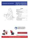
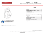
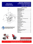
Download Pacer & Trend Hydrants - AMERICAN – The Right Way.
Transcript
Fire Hydrant Rod Replacement and Remediation Program Owner's Instructions Pacer & Trend Hydrants Pacer Hydrant Trend Hydrant Model WB67-250 Model WB77 Pacer Hydrant Parts Descriptions . . . . . . . . . . . . . . . . . . . . . 5 Trend Hydrant Parts Descriptions . . . . . . . . . . . . . . . . . . . . 12 Typical Rod Replacement Parts List - Pacer . . . . . . . . . . . 17 “Use As Needed" Parts List - Pacer . . . . . . . . . . . . . . . . . . 17 Typical Operating Mechanism Assy Parts List - Trend . . 18 “Use As Needed" Parts List - Trend . . . . . . . . . . . . . . . . . . 18 â American-Darling Valve and Waterous Date H-475 09/09/08 Revision Date Table of Contents Safety Information . . . . . . . . . . . . . . . . . . . . . . . . . . . . 1 Introduction . . . . . . . . . . . . . . . . . . . . . . . . . . . . . . . . . . . . . . . . . 2 General Description . . . . . . . . . . . . . . . . . . . . . . . . . . . . . . . . 2 Remediation / Replacement Equipment and Materials . 2 Pacer Ductile Iron Hydrants from 1999 - 2004 . . . . . . . . 3 Pacer Remediation / Replacement Procedure . . . . . . . . . . . 3 Identifying Affected Pacer Fire Hydrants . . . . . . . . . . . . 3 Exposing the Upper Operating Rod . . . . . . . . . . . . . . . . 6 Operating Rod Removal . . . . . . . . . . . . . . . . . . . . . . . . . . 6 Cleaning Hydrant Parts . . . . . . . . . . . . . . . . . . . . . . . . . . . 6 Operating Rod Installation . . . . . . . . . . . . . . . . . . . . . . . . 6 Hydrant Reassembly . . . . . . . . . . . . . . . . . . . . . . . . . . . . . 7 Replacement of Extraordinary Parts . . . . . . . . . . . . . . . . 8 Recording Information on Log Sheets . . . . . . . . . . . . . . 8 Storing, Labeling and Packaging Rods for Return . . . . 8 Arranging for Shipping Rods . . . . . . . . . . . . . . . . . . . . . . 9 Trend Hydrants (WB77) from 1999 - 2004 . . . . . . . . . . . . 10 Operating Mechanism Replacement Procedure . . . . . . . . . 10 Locating Affected Trend Fire Hydrants . . . . . . . . . . . . . 10 Replacement of the Operating Mechanism Assembly 13 Hydrant Reassembly . . . . . . . . . . . . . . . . . . . . . . . . . . . . 13 Replacement of Extraordinary Parts . . . . . . . . . . . . . . . 14 Recording Information on Log Sheets . . . . . . . . . . . . . 14 Storing, Labeling and Packaging Rods for Return . . . 14 Arranging for Shipping Rods . . . . . . . . . . . . . . . . . . . . . 15 Appendices . . . . . . . . . . . . . . . . . . . . . . . . . . . . . . . . . . . . . . . 16 Appendix A - Pacer Parts Lists . . . . . . . . . . . . . . . . . . . 17 Appendix B - Trend Parts Lists . . . . . . . . . . . . . . . . . . . 18 Appendix C - Waterous Hydrant Enamel . . . . . . . . . . . 19 Appendix D - Material Safety Data Sheets . . . . . . . . . 20 Appendix E - Shipping Label . . . . . . . . . . . . . . . . . . . . . 53 Appendix F- Contact Information . . . . . . . . . . . . . . . . . 54 Tables 1. 2. 3. 4. 5. 6. Form No. Illustrations 1. 2. 3. 4. 5. 6. 7. 8. 9. 10. Pacer Model Hydrant Comparison . . . . . . . . . . . . . . . . . 3 Pacer Hydrant Identification Markings . . . . . . . . . . . . . . 4 Exploded View of Pacer Hydrant . . . . . . . . . . . . . . . . . . 5 Upper Standpipe (Breakable Flange Orientation) . . . . . 7 Plate Installation . . . . . . . . . . . . . . . . . . . . . . . . . . . . . . . . . 7 Labeled Rod Example - Pacer . . . . . . . . . . . . . . . . . . . . . 8 Trend Model Hydrant Comparison . . . . . . . . . . . . . . . 10 Trend Hydrant Identification Markings . . . . . . . . . . . . 11 Exploded View of Trend Hydrant . . . . . . . . . . . . . . . . 12 Labeled Rod Example - Trend . . . . . . . . . . . . . . . . . . . 14 Read through instructions carefully before performing any repairs to the Pacer or Trend Hydrant. Waterous Company 125 Hardman Avenue South, South St. Paul, Minnesota 55075 USA (651) 450-5000 Instructions subject to change without notice. Safety Information Read through the safety information prior to performing any repairs or replacement of the hydrant operating rod. ! WARNING Solvent Vapor Hazard. May result in respiratory problems or nausea. When cleaning parts of the hydrant with cleaning solvent, avoid inhaling the solvent vapors. Use only in well ventilated areas. ! CAUTION ! WARNING Lifting Hazard. May result in personal injury. Ensure physical capability before attempting to lift, and always use proper lifting techniques to avoid personal injury. Combustible Vapor Hazard. May result in a flash fire. When cleaning parts of the hydrant with cleaning solvent, use only in areas with adequate ventilation. Vapors released from the solvent are combustible and may cause a flash fire should an ignition source be present. ! WARNING Traffic Protection. May result in serious personal injury or death. When repairing the hydrant, use appropriate signage and cautionary items to protect the worker from being struck by a moving vehicle. ! CAUTION Loud noise levels. May cause tem porary or permanent hearing loss. Always wear protective hearing equip ment (custom molded ear plugs, sound-reducing head gear) when op erating the die grinder. ! WARNING Spray Paint Vapor Hazard. May result in irritations to the eyes, nose and throat. When using spray paint to touch up areas of the hy drant, use only with adequate ventilation and wear appropriate breathing protection to prevent irritations from the paint vapors. ! CAUTION Metallic Particle Hazard. May cause irritation or permanent injury to the eyes. Always wear proper eye protection when using the die grinder to prevent metallic particles from entering the eye. H-475 Rev: Page 1 of 54 Introduction and Project General Description Remediation of the Pacer fire hydrants entails locating the affected fire hydrants, removal of the upper operating rod, removal and cleaning of the grease and oil from the in ternal parts, installation of a replacement operating rod, applying lubrication, reassembly, and testing. These instructions cover the course of action for remedi ating and replacing upper operating rods of Waterous Pacer and Trend Fire Hydrants that were lubricated with Chevron Food Grade Grease. The instructions are sep arated into two parts – the first part addresses the Pacer Model WB67-250 with cast year markings of 1999 through 2004, and the second part addresses the Trend Model WB77 with cast year markings of 1999 through 2004. Remediation of the Trend fire hydrants entails locating the affected fire hydrants, removal of the operating mechan ism assembly as a single unit, installation of a replace ment operating mechanism assembly, applying lubrica tion, reassembly, and testing. Remediation / Operating Rod Replacement Equipment and Materials Waterous Company recommends the use of the following equipment and materials for the remediation of these fire hydrants. Material Safety Data Sheets (MSDS) covering some of the materials are included in the Appendices. Parts Cleaning Solvent Pneumatic Die Grinder and Rotary Wire Brushes A degreasing solvent with chemistry similar to mineral spirits, such as Safety-Kleen Premium Gold Solvent, is used for removal and cleaning of existing grease and oil on parts. A high-speed (20,000 rpm), hand-held, air or electricpowered tool with mandrel-mounted wire brushes can be used to clean the nozzle cap threads. An example of a die-grinder is Chicago Pneumatic brand RediPower model RP9111, 20,000 rpm free speed, 0.46 hp, die-grinder with 1/4inch collet. An example of a rotary wire brush is Weiler brand, item number 17909, narrow-face, concave, 2-1/2 inch diameter, .006 inch wire-size, 20,000 maximum RPM. Waterous Hydrant Lubricating Grease Waterous part number V 3174, Citgo Clarion Food Machinery Grease, furnished in a 5-pound plastic tub, is used where lubricating with grease is specified. Waterous part number V 1934, which is the same grease in a 1-pint tub, may also be used. Waterous will furnish appropriate quantities of this material. Angle-Drive Impact Wrench A battery-powered or pneumatic angle-drive wrench per mits rapid removal and installation of the coupling nuts and upper rod for some break-off lengths without remov ing the upper standpipe. An example of a battery- powered wrench is Ingersoll Rand IQv Series Cordless Ratchet, Model R380, with 3/8 in. drive, and 14.4V re chargeable battery. Waterous Hydrant Lubricating Oil Waterous part number V 3175, Lubriplate FMO-350-AW USP petroleum mineral oil with additives, furnished in 1-gallon plastic bottles, is used where lubricating with oil is specified. Waterous part numbers V 1935 and V 2551, which is the same oil in 16-oz and 4-oz plastic bottles, may also be used. Waterous will furnish appropriate quantities of this material. Parts Washer and Cleaning Brush A portable parts-washer with 5-gallon solvent capacity, hinged cover, air or electric powered circulating pump and brush with integral flow-through hose for dispensing pres surized solvent is suitable for cleaning the grease and oil from parts. An example of a parts washer is Safety-Kleen Manual Bench-top Parts Washer, Model 14, part number 1160, with 115 VAC 0.3A electric circulating pump. H-475 Rev: Page 2 of 54 Ductile Iron Pacer Hydrants from 1999 through 2004 Pacer Remediation / Rod Replacement Procedure Identifying Affected Pacer Fire Hydrants ductile-iron Pacer has two separate flanges at the joint between the nozzle section and the upper standpipe, each of which is about 1-inch in thickness. The gray-iron Pacer has a single flange at that location that is about 3-inches in thickness. For illustrations showing these visual differences and the location of the cast year mark ings, see Figures 1 and 2. The affected Waterous Pacer fire hydrants include only ductile-iron versions of Pacer hydrants that bear cast year markings of 1999 through 2004. Ductile-iron Pacer hy drants were manufactured beginning in 1996 and can be visually differentiated from the older gray-iron Pacer hy drants, which were manufactured from 1967 until 1996, by the appearance of the flange at the nozzle section. The Figure 1. Pacer Model Hydrant Comparison Single Flange Two Flanges Gray-Iron Ductile-Iron Model WB67 Model WB67-250 This Model is Not Part of Remediation Program H-475 This Model with 1999-2004 Year Markings are Part of Remediation Program. Rev: Page 3 of 54 Figure 2. Pacer Hydrant Identification Markings Ductile-Iron Pacer Models that are affected Two Flanges Traffic Model has flanges at groundline. At Nozzle Section / Standpipe Joint (Upper Flange Integral with Nozzle Section) TRAFFIC MODEL WB67-250 NON-TRAFFIC MODEL W67-250 5-1/4 inch Hydrant Valve Size 1999 Through 2004 Years of Manufacture 250 Working Pressure Bury Depth (Feet - Inches) Waterous (Company Name) IDENTIFICATION MARKINGS 5-1/4” Ductile Iron Pacer - Models W67-250 and WB67-250 Gray-Iron Pacer Models that are not affected. Single Flange Traffic Model has flanges at groundline. At Nozzle Section / Standpipe Joint (Upper Flange Integral with Nozzle Section) TRAFFIC MODEL WB67 NON-TRAFFIC MODEL W67 Year of Manufacture 150 Working Pressure Bury Depth (Feet - Inches) 5-1/4 inch Hydrant Valve Size Waterous (Company Name) TYPICAL IDENTIFICATION MARKINGS 5-1/4” Gray Iron Pacer - Models WB67 and W67 H-475 Rev: Page 4 of 54 Figure 3. Exploded View of Pacer Hydrant Table 1. Pacer Hydrants Parts Descriptions 3 5 6A 6B 6C 7 8 9A, 9B 10 11 12 16 17 17A 17B 25 28 29 29 30 31 34 35 36 37 40 54 56 57 59 60 61 61 62B 63 64 67 71 72 77 81 82 83 84 85 86 87 88 89 90 92 H-475 Rev: O-ring (Lower valve seat), 5-5/8 x 6-3/64 Lower standpipe gasket Hex hd bolt, 5/8-11 x 3-3/4 in. Hex hd bolt, 5/8-11 x 3 in. Hex nut, 5/8-11 Drain plunger Cotter pin, 1/4 x 1-1/2 in. Nozzle cap chain, single or double Nozzle cap, hose or pumper Cap gasket, hose or pumper Nozzle, hose or pumper Flat hd screw, 1/4-20 x 1/2 in. Operating nut (one-piece) Lower operating nut Upper operating nut Rod bushing Rod (Non-Traffic model) Lower standpipe (Traffic model) Standpipe (Non-Traffic model) Crossarm Valve seat Upper valve washer Main valve rubber Lower valve washer Hydrant bottom Upper standpipe (Traffic model) Drain bushing Support wheel O-ring (Operating nut), 1-1/2 x 1-3/4 O-ring (Support wheel), 1-1/8 x 1-3/8 Nozzle section Bury depth plate Bury depth plate washer Upper standpipe flange Standpipe flange Flange lock ring Coupling sleeve (two-halves) Upper rod (Traffic model) Lower rod (Traffic model) O-ring (Upper valve seat), 5-7/8 x 6-1/4 Groove pin, 3/32 x 7/16 in. O-ring (Upper tube seal), 2-3/8 x 2-5/8 O-ring (Lower tube seal), 1-7/8 x 2-1/8 Support wheel / lower standpipe gasket Support tube Stop nut, 1”- 8 Coupling nut, 1/2-20 Coupling stud, 1/2-20 x 2-9/16 in. Nozzle section bushing Thrust ring Upper standpipe gasket Page 5 of 54 NOTE: Where grease is specified, use Citgo Clarionâ Food Machinery Grease No. 2 (formerly named Citgo Mysticâ FG-2 Food Machinery Grease). NOTE: Removal of the upper operating rod may be performed while the main hydrant valve is closed and pressurized, or the auxiliary (hydrant shut-off) valve may be closed prior to performing this work. Refer to Figure 3 to find locations of parts referenced in instructions. ! WARNING Traffic Protection. May result in serious personal injury or death. When repairing the hydrant, use appropriate signage and cautionary items to protect the worker from being struck by a moving vehicle. Exposing the Upper Operating Rod 1. Check that the hydrant main valve is in the closed position and remove a nozzle cap to verify that water pressure has been relieved from the inside of the hydrant. 2. At the nozzle section, remove bolts (6A), nuts (6C) and allow flange (62B) to slide down the upper (breakoff) standpipe. Depth plate and plain washer (61) will come off with bolts. 3. Turn upper operating nut (17B) or weathershield nut (101) in the opening direction to separate the nozzle section (60) and the support wheel (56). If the operat ing nut is the one-piece type and the weathershield is in place, the nut must be completely unthreaded from the operating rod before removing the nozzle section. Remove the nozzle section. ! CAUTION Lifting Hazard. May result in personal injury. Ensure physical capability before attempting to lift, and always use proper lifting techniques to avoid personal injury. 4. Remove operating nut (17B) from the nozzle section (60). To remove the weathershield-type operating nut, drive out pin (102) and remove weathershield (101), then remove the upper operating nut. NOTE: Bushing (89) is cemented into the nozzle section (60). Removing it is not necessary unless it is damaged. If replacement is necessary, contact the Waterous Company. 5. Unscrew lower operating nut (17A) and remove support tube (85). 6. Unscrew hex stop nut (86) from operating rod (71) and remove support wheel (56). H-475 Operating Rod Removal Two methods may be used for removing the operating rod. The first method is to remove the upper standpipe (see Step 1) and the second is to remove the rod with the upper standpipe in place (continue to Step 2). 1. Removing the Upper Standpipe: If removing the upper standpipe (40), remove bolts (6B) and nuts (6C) and lift off upper standpipe (40). Note that flange (113) and (62B) will remain attached to the upper standpipe (40). It is not necessary to remove these flanges. 2. Remove two coupling nuts (87), leaving one nut in place on the stud and coupling of the lower rod and one on the stud and coupling on the opposite side of the upper rod. Remove the upper operating rod. 3. Remove the coupling half (67) from the upper rod. 4. Operating rod will be returned to Waterous. See Storing, Labeling and Packaging Rods for Return on Page 8. Cleaning Hydrant Parts 1. Using a bottle brush and solvent-type parts washer, remove and thoroughly clean any existing grease from the support wheel (56), the support tube (85), the stop nut (86) and the upper and lower operating nut (17A and 17B, or in the case of the one-piece operat ing nut, 17). ! WARNING Solvent Vapor Hazard. The following injuries or conditions may occur when using cleaning solvent. Inhalation When cleaning parts of the hydrant with cleaning solvent, avoid inhaling vapors. Use only in well ventil ated areas. Combustion When cleaning parts of the hydrant with cleaning solvent, use only in areas with adequate ventilation. Vapors released from the solvent are combustible and may cause a flash fire should an ignition source be present. 2. Submerge parts in water to remove traces of the solvent or grease from the cleaned parts. NOTE: Properly dispose of or recycle used solvent in accordance with the solvent manufac turer's recommendations and any local and state requirements. 3. Examine the O-ring seals for damage and replace any damaged seals. Operating Rod Installation 1. Install one coupling half (67) and new nut (87) onto the upper rod of the replacement rod and tighten nut with 30 ft-lbs of torque. 2. Place the replacement upper rod into position above the lower rod, inserting the stud of the upper rod into the hole of the coupling half (67) that remained at tached to the lower rod. Thread on new coupling nuts and tighten the nuts on the studs with 30 ft-lbs of torque. Rev: Page 6 of 54 Hydrant Reassembly If the upper standpipe was left in place, skip to Step 3. 1. Orientate upper standpipe (40) as shown in Figure 4. Figure 4. Upper Standpipe (Breakable Flange Orientation) 12. Install bury-depth plate and washer (61) and any other plates and washers that may have been removed such as extension or “No-Drain" plates, in the proper positions. Install the “Rod-Replaced" plate to identify that the rod was replaced and cleaned in accordance with these instructions. See Figure 5 for the proper positions for these plates. Figure 5. Plate Installation Reinstall existing bury depth plate and washer (REF 61) Install “Rod Replaced" plate (REF 61) IL1439-7B 2. Place gasket (92) on the lower standpipe with the lip pointing downward. Position the upper standpipe (40) on the lower standpipe and install bolts (6B) through the flanges (113) and (63). Install nuts (6C) and tight en the four bolts evenly. 3. Apply grease to the O-ring and gasket grooves in sup port wheel (56), and to the bore and three O-rings (59). Install the two gaskets (84) and apply grease to the lower tube seal (83). 4. Install hex stop nut (86), turning it down to end of thread. Snug up with a torque of 30 lb-ft (30 lb at end of 12 in. wrench). 5. Apply grease to the brass bushing on the rod (71) and to the lower end of the operating threads. 6. Grease O-ring (82) in upper end of support tube (85). Slide tube down over operating rod (71) until it is seated on support wheel (56). 7. Pour 4-oz of lubricating oil into the support tube (85). 8. Grease lower bearing surface of operating nut (17A or 17). Screw lower operating nut onto rod while center ing support wheel (56) on the standpipe. Tighten op erating nut (17A or 17) to securely clamp support wheel (56) against upper standpipe (40). Be sure sup port wheel (56) is centered on upper standpipe (40). 9. Apply grease to all of the exposed operating rod threads. 10. Grease Teflon thrust ring (90) and O-ring (57) in oper ating nut (17B or 17). If hydrant has a two-piece oper ating nut, set upper operating nut (17B) on lower op erating nut (17A) and engage lugs in slots. 11. Carefully lower nozzle section (60) over operating nut (17B or 17) until it seats on support wheel (56). Rotate nozzle section (60) to desired position. H-475 Reinstall existing “No Drain" plate and washer (REF 125) or extension length plate (REF 157) 13. Make sure flange (62B) is seated properly under the nozzle section and tighten all bolts and nuts evenly to 80 to 100 lb-ft (80 to 100 lb. force applied at the end of 12 in. wrench). ! CAUTION Loud noise levels. May cause tempo rary or permanent hearing loss. Always wear protective hearing equip ment (custom molded ear plugs, sound-reducing head gear) when op erating the die grinder. ! CAUTION Metallic Particle Hazard. May cause irritation or permanent injury to the eyes. Always wear proper eye protection when using the die grinder to prevent metallic particles from entering the eye. 14. Remove the nozzle caps, clean the cap threads as needed and lubricate the cap threads with grease. 15. Leaving one cap removed, install the other caps onto the nozzles. Rev: Page 7 of 54 16. Perform the following test to verify the function of the hydrant and its connection to a pressurized water source: a. Turn the operating nut slowly in the opening direc tion until water flows from the nozzle. Storing, Labeling and Packaging Rods for Return 1. Rods stored for return to Waterous must be protected from rain or other sources of water and moisture. 2. Certain rods will be refurbished and re-used so spe cial handling and protection during shipping is re quired to prevent damage. 3. Create a unique hydrant Identification number. a. Each rod should be labeled with a unique identi fication (ID) number. b. If flushing of the hydrant is to be performed, do so now. See AWWA Manual M17, Installation, Field Testing and Maintenance of Fire Hydrants, for special cautions to be observed and warnings about the use of rigid diverters when flushing. c. Slowly turn the operating nut in the closing-direc tion until flow stops. d. Install the cap on the open nozzle. e. Counting the number of turns, open the main valve to verify that it takes at least 18-turns to open fully. Verify ease of operation. f. With the main valve fully open, check for leaks from joints. Remove the oil level plug and check for leakage of water into the oil reservoir. Replace the plug. g. Close the main valve completely and then turn the operating nut in the opening-direction about 1/4-turn to relieve force from the operating mech anism. h. Loosen a nozzle cap to verify that pressure has been fully relieved from the hydrant and then re move the cap. i. For draining type hydrants, verify that the stand pipe is draining. Pump water from the standpipe of non-draining type hydrants. j. As needed, repair any leaks and/or conditions that prevent full opening of the main valve. b. The first four digits of the ID should be the GRA number that was assigned during the process of ordering parts and materials for this project. c. Following the GRA number place a dash (-) and two or three letters of the service crew’s initials. d. Following the service crew’s initials write a se quential number that begins at one (1) for the first rod and increases by one for each rod removed by a crew. e. An example of an ID number is “1035-JTS247” for a service contractor whose GRA number is 1035, the service technician is John T. Smith, and the rod is the 247th one to be removed by John Smith’s service crew. 4. Use a light-colored paint-marker to write the rod hy drant ID code legibly on the rod in an area adjacent to the operating threads. Clean grease or oil from the area as needed to achieve adhesion between the marking paint and the steel surface of the rod. Figure 6. Packaged and Labeled Rod Example - Pacer Replacement of Extraordinary Parts Coupling Nuts (87) Certain parts will be supplied to you by Waterous as they are needed to replace unusable parts that are not routinely supplied and do not appear on the list of typical rod replacement parts in Table 3 of Appendix A. Other parts may be needed for repairs unrelated to the remedi ation project. See Appendix A for the list of “Use as Needed” parts in Table 4 and for instructions for identify ing the specific parts that are needed for the particular hydrants. GRA # Followed by a Dash Unique Sequential Number Recording Information on Log Sheet 1. Upon completion of the remediation and rod replace ment, pertinent information should be recorded on the Waterous Log Sheet, form number H-445. a. Information recorded on the Log Sheet should include the following: i. The city or water district where the hydrant is located ii. The address or other description of the hy drant's location iii. The hydrant's ID number. (See the following section for more details.) iv. The date that the remediation and rod re placement was completed. v. The hydrant model. vi. The hydrant's year of manufacture. H-475 Cardboard Tube 5. Place cardboard tube over operating threads and cop per bushing and thread the used nuts (87) onto the studs to protect the rod during shipment. 6. Stack the rods neatly in a wood-sided pallet or plastic shipping tote, alternating the direction of each rod to stagger the positions of the protruding coupling studs. The maximum capacity of each wood-sided pallet or tote is 1800 pounds. The maximum quantities of rods that may be shipped per pallet or tote are listed below: a. 275-rods of 20-5/8 inch length (from hydrants with 10-inch break-off standpipe length) b. 200-rods of 26-5/8 inch length (from hydrants with 16-inch break-off standpipe length) Rev: Page 8 of 54 d. 135-rods of 38-5/8 inch length (from hydrants with 28-inch break-off standpipe length) 3. Complete a Waterous bill of lading (BOL) for each shipment. Each shipment may consist of one or more containers. Note the approximate weight of each con tainer on the BOL. e. 115-rods of 44-5/8 inch length (from hydrants with 34-inch break-off standpipe length) a. For estimating the weight of the rods and contain ers, please refer to the weights shown below: c. 165-rods of 32-5/8 inch length (from hydrants with 22-inch break-off standpipe length) i. Wood-sided pallet: 90 pounds each ii. 20-5/8 inch rod: 6.17 pounds each iii. 26-5/8 inch rod: 8.24 pounds each iv. 32-5/8 inch rod: 10.31 pounds each v. 38-5/8 inch rod: 12.38 pounds each vi. 44-5/8 inch rod: 14.45 pounds each 4. Contact the designated shipping company to schedule a pick-up. Arranging for Shipping Rods 1. Smaller quantities of rods may be returned when ne cessary, but if possible, accumulate at least 50 rods before arranging for shipping. 2. Securely attach a Waterous shipping label to each pallet or container of rods to be returned. Write the GRA number and the number of rods that are in each container on each shipping label. H-475 Rev: Page 9 of 54 Trend Hydrants (WB77) from 1999 through 2004 Operating Mechanism Replacement Procedure Locating Affected Trend Fire Hydrants The affected Waterous Trend fire hydrants include only the Model WB77 versions that bear cast year markings of 1999 through 2004. Trend Model WB77 fire hydrants were manufactured beginning in 1987 and can be visually differentiated from the older Model WT77 and WT77D hydrants, which were manufactured from 1977 until 1987. Following is a list of the visual differences between these models. · The WT77 & WT77D “Old Style” Trend nozzle section extends down to the groundline. · The WB-77 Trend has a short nozzle section with two flanges at the ground line. For illustrations showing these visual differences and the location of the cast year markings, see Figures 7 and 8. Figure 7. Trend Model Hydrant Comparisons Nozzle Section to Groundline Single Flange Two Flanges WT77 & WT77D “Old” Style Built from 1977 to 1987 WB77 This Model with 1999-2004 Year Markings are Part of Remediation Program. This Model is Not Part of Remediation Program H-475 Rev: Page 10 of 54 Figure 8. Trend Hydrant Identification Markings 1999-2004 WB77 Trend Year of Manufacture Bury Depth (Feet-Inches) Models that are affected 200 Working Pressure (“150” prior to 2001) Waterous Company Name “Short” nozzle section with two flanges at groundline 4-3/4 Hydrant Valve Size Waterous Company Name Upper Flange with notched corners is designed to break. FRONT VIEW NEW STYLE TREND Model WB77: Built from 1987 to 2006 REAR VIEW 4-3/4” TREND HYDRANT Available in Traffic Configuration Only WT77 & WT77D Trend “Old” Style Operating Nut Flat Head Screw: Dry Top Model WT77D Socket Head Pipe Plug: Wet Top Model WT77 Nozzle section extends to groundline with single flange at groundline Single Flange at groundline is designed to break. Company Name Year of Manufacture Working Pressure Hydrant Valve Size Bury Depth (Feet-Inches) Models that are not affected. REAR VIEW FRONT VIEW OLD STYLE TREND Dry Top Model WT77D: Built from 1977 to 1996 Wet Top Model WT77: Built from 1977 to 1987 H-475 Rev: Page 11 of 54 Figure 9. Exploded View of Trend Hydrant (WB77) Table 2. Trend Hydrants Part Descriptions 1 2 3 *4 5 *6 7 8 9 10 11 12 13 14 15 16 17A 17B 18 19 21 22 23 24 *37 *38 *39 46 49 53 54 55 56 57 58 59 77 78 79 80 *99 Flat hd screw, 1/4-20 x 1/2 in. Weathershield nut Spirol pin, hvy, 1/2 x 2-3/4 in. O-ring (weathershield nut, operating nut housing, Nozzle section), 1-3/4 x 2 Thrust bushing Operating nut Nozzle cap, hose or pumper Cap gasket, hose or pumper Nozzle, hose or pumper Nozzle cap chain, single or double Nozzle section Upper rod Coupling stud, 1/2-20 x 2-9/16 in. Coupling sleeve (two halves) Coupling nut, 1/2-20 Standpipe gasket Hex hd bolt, 5/8-11 x 3 in. Hex nut, 5/8-11 Bury depth plate washer Bury depth plate Lock ring clamp Flange lock ring Lower rod Lower standpipe Operating nut housing O-ring (upper rod), 1 x 1-1/4 Spirol pin, hvy, 1/4 x 2-1/4 in. Hex hd bolt, 5/8-11 x 3 in. Standpipe gasket (with lip) Pumper nozzle retainer Hose nozzle retainer O-ring (pumper nozzle), 5-1/4 x 5-3/4 O-ring (hose nozzle), 3-1/4 x 3-5/8 Upper standpipe Breakable flange Standpipe flange Nozzle, pumper, Storz (with cap and gasket) Nozzle cap, pumper, Storz Cap gasket, pumper, Storz Thrust washer (Teflon) Operating Mechanism Assembly * Operating Mechanism Assembly components. H-475 Rev: Page 12 of 54 NOTE: Removal of the operating mechanism as sembly may be performed while the main hydrant valve is closed and pressurized, or the auxiliary (hydrant shut-off) valve may be closed prior to performing this work. Refer to Figure 9 to find locations of parts referenced in instructions. Replacement of the Operating Mechanism Assembly 1. Check that the hydrant main valve is in the closed position and remove a nozzle cap to verify that water pressure has been relieved from the inside of the hydrant. 2. Drive out spirol pin (3) and turn the weathershield nut (2) in the closing direction to break the bond between the weathershield nut and the operating nut (6). 3. Remove the weathershield nut by prying between the weathershield and the nozzle section (11). 4. Remove hex hd bolts (46) and hex nuts (17B) at the traffic flange between the upper standpipe (57) and lower standpipe (24). 5. Insert a punch or rod into the 1/2-inch diameter cross- hole in the operating nut (6) and turn the operating nut in the opening direction until it is completely un threaded from the operating rod. 6. Remove nozzle section (11) and upper standpipe (57) by lifting as a unit over the operating rod. ! CAUTION Lifting Hazard. May result in personal injury. Ensure physical capability before attempting to lift, and always use proper lifting techniques to avoid personal injury. 7. Push the operating nut (6) into the interior of the nozzle section (11) and remove it from the upper standpipe (57). 8. Remove upper thrust bushing (5) from the nozzle sec tion (11). Remove O-ring (4) and lower thrust bushing (5) from operating nut (6). 9. Remove two coupling nuts (87), leaving one nut in place on the stud and coupling of the lower rod and one on the stud and coupling on the opposite side of the upper rod. Remove the upper operating rod and coupling half (67). 10. Remove the coupling half (67) from the upper rod. 11. Thread the operating nut (6) onto the rod threads to protect the mechanism during shipping. 12. Operating mechanism assembly will be returned to Waterous. See Storing, Labeling and Packaging Rods for Return on Page 14. 1. Install one coupling half (67) and a new nut (87) onto the upper rod of the replacement rod and tighten nut with 30 ft-lbs of torque. 2. Place the replacement upper rod into position above the lower rod, inserting the stud of the upper rod into the hole of the coupling half (67) that remained at tached to the lower rod. Thread on new coupling nuts and tighten the nuts on the studs with 30 ft-lbs of torque. 3. Grease thrust and bearing surfaces of operating nut (6). Slip Teflon thrust washer (80) and one thrust bushing (5) over operating nut. The flange of the thrust bearing (5) must rest against the thrust washer (80) and the thrust surface of the operating nut (6). 4. Make sure lock ring (22) is properly installed in the standpipe groove. 5. Install standpipe gasket (49) on lower standpipe. 6. Lower nozzle section (11) and upper standpipe (57) as one piece onto operating nut (6) and rotate to de sired position. 7. Insert a suitable punch or screwdriver in 1/2 in. diame ter hole in operating nut (6). Turn in the closing direc tion until the lower face of the upper standpipe (57) barely contacts the gasket (16). 8. Install hex hd screws (49) and the Rod Replaced plate and hex nuts (17B) between upper standpipe (57) and lower standpipe (24) and tighten. 9. Slip O-ring (4) over operating nut (6) and into the bore of the nozzle section (11). 10. Install upper thrust bushing (5) on operating nut (6). Push down until bushing flange rests on top of the nozzle section (11). 11. Add 2 oz. of oil through opening in operating nut (6). CAUTION Do not add more than 2 oz. of oil. 12. Install weathershield cap (2) on operating nut (6). Line up holes in nut and cap and install spirol pin (3). ! CAUTION Loud noise levels. May cause tempo rary or permanent hearing loss. Always wear protective hearing equip ment (custom molded ear plugs, sound-reducing head gear) when op erating the die grinder. ! CAUTION Metallic Particle Hazard. May cause irritation or permanent injury to the eyes. Always wear proper eye protection when using the die grinder to prevent metallic particles from entering the eye. Hydrant Reassembly NOTE: Where grease is specified, use Citgo Clarionâ Food Machinery Grease No. 2 (formerly named Citgo Mysticâ FG-2 Food Machinery Grease). H-475 13. Remove the nozzle caps, clean the cap threads as needed and lubricate the cap threads with grease. Rev: Page 13 of 54 iv. The date that the remediation and rod re placement was completed. v. The hydrant model. vi. The hydrant's year of manufacture. 14. Leaving one cap removed, install the other caps onto the nozzles. 15. Perform the following test to verify the function of the hydrant and its connection to a pressurized water source: b. Turn the operating nut slowly in the opening direc tion until water flows from the nozzle. c. Storing, Labeling and Packaging Rods for Return 1. Operating mechanism assemblies stored for return to Waterous should be protected from rain or other sources of water and moisture. 2. Certain parts of the operating mechanisms will be refurbished and re-used so special handling and pro tection during shipping is required to prevent damage. 3. The operating nut must be threaded onto the operat ing rod threads to protect the sealing surface of the nut. 4. The used coupling nuts, V1853, should be threaded onto the studs of the rod to protect the threads. 5. Create a hydrant Identification number. If flushing of the hydrant is to be performed, do so now. See AWWA Manual M17, Installation, Field Testing and Maintenance of Fire Hydrants, for special cautions to be observed and warnings about the use of rigid diverters when flushing. d. Slowly turn the operating nut in the closing-direc tion until flow stops. e. Install the cap on the open nozzle. f. Counting the number of turns, open the main valve to verify that it takes at least 18-turns to open fully. Verify ease of operation. g. With the main valve fully open, check for leaks from joints. Remove the oil level plug and check for leakage of water into the oil reservoir. Replace the plug. a. Each rod should be labeled with a unique identi fication (ID) number. b. The first four digits of the ID shall be the GRA number that was assigned during the process of ordering parts and materials for this project. h. Close the main valve completely and then turn the operating nut in the opening-direction about 1/4-turn to relieve force from the operating mech anism. i. c. Loosen a nozzle cap to verify that pressure has been fully relieved from the hydrant and then re move the cap. j. For draining type hydrants, verify that the stand pipe is draining. Pump water from the standpipe of non-draining type hydrants. k. As needed, repair any leaks and/or conditions that prevent full opening of the main valve. Following the GRA number should be a dash (-) and two or three letters of the service crew’s ini tials. d. Following the service crew’s initials should be a sequential number that begins at one (1) for the first rod and increases by one for each rod re moved by a crew. e. An example of an ID number is “1035-JTS247” for a service contractor whose GRA number is 1035, the service technician is John T. Smith, and the rod is the 247th one to be removed by John Smith’s service crew. Replacement of Extraordinary Parts Certain parts will be supplied to you by Waterous as they are needed to replace unusable parts that are not routinely supplied and do not appear on the list of typical rod replacement parts in Table 5 of Appendix B. Other parts may be needed for repairs unrelated to the remedi ation project. See Appendix B for the list of “Use as Needed” parts in Table 6 and for instructions for identify ing the specific parts that are needed for the particular hydrants. 6. Use a light-colored paint-marker to write the rod hy drant ID code legibly on the rod in an area adjacent to the housing. Clean grease or oil from the area as needed to achieve adhesion between the marking paint and the steel surface of the rod. See Figure 10 for an example of a packaged and labeled rod. Figure 10. Packaged and Labeled Rod Example - Trend Coupling Nuts (15) Recording Information on Log Sheet GRA # Followed by a Dash 1. Upon completion of the remediation and rod replace ment, pertinent information should be recorded on the Waterous Log Sheet, form number H-445. a. Information recorded on the Log Sheet shall in clude the following: i. The city or water district where the hydrant is located ii. The address or other description of the hy drant's location iii. The hydrant's ID number. (See the following section for more details.) H-475 Unique Sequential Number Operating Nut Rev: Page 14 of 54 7. Stack the assemblies neatly in a wood-sided pallet or plastic tote, alternating the direction of each rod to stagger the positions of the protruding coupling studs. The maximum capacity of each wood-sided pallet or tote is 1800 pounds. The maximum quantity of oper ating mechanism assemblies that may be shipped in each pallet or tote is 100. Arranging for Shipping Rods 1. Smaller quantities of rods may be returned when ne cessary, but if possible, accumulate at least 50 rods before arranging for shipping. 2. Securely attach a Waterous shipping label to each pallet or container of rods to be returned. Write the GRA number and the number of rods that are in each container on each shipping label. 3. Complete a Waterous bill of lading (BOL) for each shipment. Each shipment may consist of one or more containers. Note the approximate weight of each con tainer on the BOL. a. For estimating the weight of the rods and contain ers, please refer to the weights shown below: i. ii. Wood-sided pallet: 90 pounds each Operating Mechanism - 10” break-off: 14.2 lbs each iii. Operating Mechanism - 16” break-off: 16.3 lbs each 4. Contact the designated shipping company to schedule a pick-up. H-475 Rev: Page 15 of 54 Appendices Appendix A - Pacer Parts Lists (Remediation / Replacement) . . . . . . . . . . . . . . . . 17 Appendix B - Trend Parts Lists (Replacement) . . . . . . . . . . . . . . . . . . . . . . . . . . . . . 18 Appendix C - Material Safety Data Sheets . . . . . . . . . . . . . . . . . . . . . . . . . . . . . . . . . . 19 Appendix D - Shipping Label . . . . . . . . . . . . . . . . . . . . . . . . . . . . . . . . . . . . . . . . . . . . . 47 Appendix E - Contact Information . . . . . . . . . . . . . . . . . . . . . . . . . . . . . . . . . . . . . . . . . 48 H-475 Rev: Page 16 of 54 Appendix A - Pacer Rod Replacement Parts Lists Items listed in Table 3 are supplied for use for all hydrants requiring removal and replacement of the grease and rod. Items listed in Table 4 are provided when requested to be “used-as-needed” to replace parts removed and found to be unusable. Table 3. Typical Rod Replacement Parts List - Pacer Hydrants Ref No. 71 61 87 Part Number Description 63396 V 3175 V 3174 V 3546 V 3547 73087-L (typical, See Note 1) W 4010-CA V 1853 Rod Replaced Plate Hydrant Lubricant, Mineral Oil, 1 Gallon Food Grade Grease, 5 lbs Bottle Brush Grease Application Brush, 5/8 in. diameter Upper Rod Assembly Plain Washer, 5/8 in. Coupling Nut, 1/2-20 UNF Quantity per Hydrant 1 1 Gallon / 30 hydrants 5 lbs / 35 hydrants N/A N/A 1 1 1 Note: 1. When ordering Ref. No. 71, Upper Rod Assembly, the opening direction (Open-Left or Open-Right) and the upper standpipe length must be specified. Table 4. Rod Replacement “Use As Needed” Parts List - Pacer Hydrants Ref No. Part Number Description 6A 6B 6C 7 7 10 11 11 10 17 17A 17B 56 57 59 62B 63 64 67 82 83 84 85 86 90 92 99 102 113 116 117 118 119 W 1010-60HTSP W 1010-48HTSP W 2010-SP 6493-5 (typical) 6521-5 (typical) 5204-1 62489 (typical) 71996 (typical) 5044-1 62567 (typical) 51470-L (typical) 62022 72503 W3724-4D W 3718-4UH 81976 61724-2 50676 62266 W 3738-4 W 3730-4 51479 62989 W 2416-CA (typical) V 1954 52248 W 6604-B W33008-36SS 72929 W 3784-8 62585 W 3752-6 62584 (typical) Hex Head Bolt, 5/8-11 x 3-3/4 Hex Head Bolt, 5/8-11 x 3 Hex Nut, 5/8-11 Hose Cap (See Note 1) Pumper Cap (See Note 1) Hose Cap Gasket Hose Nozzle (See Note 2) Pumper Nozzle (See Note 2) Pumper Cap Gasket One Piece Operating Nut (see Note 5) Lower Operating Nut (see Note 5) Upper Operating Nut, Weather Shield Support Wheel Assembly O-ring, 1-1/2 x 1-3/4 O-ring, 1-1/8 x 1-3/8 Upper Standpipe Flange (see Note 6) Standpipe Flange (see Note 6) Lock Ring Half Coupling (Iron) O-ring, 2-3/8 x 2-5/8 O-ring, 1-7/8 x 2-1/8 Support Gasket Support Tube Stop Nut (RH Thread for Open-Left hydrants) Thrust Ring Standpipe Gasket Pipe Plug, 1/4” NPT, Recessed Socket Spirol Pin, 1/4 x 2-1/4 Breakable Standpipe Flange, G. I. Pumper Nozzle Retainer Seal Pumper Nozzle Retainer (See Note 3) Hose Nozzle Retainer Seal Hose Nozzle Retainer (See Note 4) H-475 Rev: Quantity per Hydrant 4 4 8 2 1 2 2 1 1 1 1 1 1 1 3 1 1 3 2 1 1 2 1 1 1 1 1 1 1 1 1 2 2 Notes: 1. When ordering Ref. No.7, Hose or Pumper Cap, thread specification and wrench nut number must be specified. Caps are furnished with primer coating only. The top coat is to be applied in the field to match the color of the hydrant. 2. When ordering Ref. No. 11, Hose or Pumper Nozzle, the thread specific‐ ation must be furnished. 3. The Ref. No. 117, Pumper Nozzle Retainer, is furnished with primer coating only. The top coat is to be applied in the field to match the col‐ or of the hydrant. 4. When ordering the Ref. No. 117, Hose Nozzle Retainer, the thread specification must be furnished. The Hose Nozzle Retainer is fur‐ nished with primer coating only. The top coat is to be applied in the field to match the color of the hydrant. 5. When ordering Ref No. 17, One Piece Operating Nut or 17A, Lower Operating Nut, the opening direc‐ tion must be specified. 6. The Ref No. 62B, Upper Standpipe Flange, Ref No. 63, Standpipe Flange, and Ref No. 113, Breakable Standpipe Flange, are furnished with primer coating only. The top coat is to be applied in the field to match the color of the hydrant. Page 17 of 54 Appendix B - Trend Remediation Parts Lists (Rod Replaced) Items listed in Table 5 are supplied for use on all hydrants where the operating mechanism is to be replaced. Items listed in Table 6 are provided when requested to be “used-as-needed” to replace parts removed and found to be unusable. Table 5. Typical Operating Mechanism Assembly Parts List - Trend Hydrants Ref No. Part Number Description Quantity per Hydrant 4 5 15 18 80 W 3728-4UH 51767 V 1853 W 4010-CA V 3175 V 3174 63396 51475 99 73156-L (typical) O-ring, 1-3/4 x 2 Nozzle Section Bushing Coupling Nut, 1/2-20 UNF Plain Washer, 5/8 Mineral Oil, Hydrant Lubricant, 1 Gallon Plastic Jug Food Grade Grease, 5 lb. Rod Replaced Plate Thrust Washer (Teflon) Operating Mechanism Assembly (includes parts listed below) (See Note 1) 1 2 1 1 2 oz. 5 lb / 50 hydrants 1 1 1 Operating Mechanism Assembly Ref No. Part Number Description Quantity per Hydrant 6 12 13 15 37 38 39 62225-L (typical) 62227-L (typical) 51481 V 1853 62226 W 3716-4UH W 33008-36SS Operating Nut, O.L. Upper Rod, O.L. Knurled Stud, 1/2-20 x 2-9/16 Coupling Nut, 1/2-20 UNF Operating Nut Housing O-ring, 1 x 1-1/4 in. Spirol Pin, 1/4 x 2-1/4 1 1 1 2 1 1 1 Note: 1. When ordering Ref. No. 99, Operating Mechanism Assembly, the opening direction (Open-Left or Open-Right) and the upper standpipe length must be specified. Table 6. Use-As-Needed Parts List - Trend Hydrants Ref No. Part Number Description Quantity per Hydrant 3 14 16 17B 21 22 46 49 7 7 10 10 11 11 116 117 118 119 W33016-44SS 62266 51772 W 2010-SP 61726 51771 W1010-48HTSP 52117 6493-5 (typical) 6521-5 (typical) 5204-1 5044-1 62489 (typical) 71996 (typical) W 3784-8 62585 W 3752-6 62584 (typical) Spirol Pin, 1/2 x 2-3/4 Half Coupling (Iron) Nozzle Section Gasket Hex Nut, 5/8-11 Lock Ring Clamp Lock Ring Hex Head Bolt, 5/8-11 x 3 Upper Standpipe Gasket Hose Cap (See Note 1) Pumper Cap (See Note 1) Hose Cap Gasket Pump Cap Gasket Hose Nozzle (See Note 2) Pumper Nozzle (See Note 2) Pumper Nozzle Retainer Seal Pumper Nozzle Retainer (See Note 3) Hose Nozzle Retainer Seal Hose Nozzle Retainer (See Note 4) 1 2 1 4 4 2 4 1 2 1 2 1 2 1 1 1 2 2 H-475 Rev: Notes: 1. When ordering Ref. No.7, Hose or Pumper Cap, thread specification and wrench nut number must be specified. Caps are furnished with primer coating only. The top coat is to be applied in the field to match the color of the hydrant. 2. When ordering Ref. No. 11, Hose or Pumper Nozzle, the thread specific‐ ation must be furnished. 3. The Ref. No. 117, Pumper Nozzle Retainer, is furnished with primer coating only. The top coat is to be applied in the field to match the col‐ or of the hydrant. 4. When ordering the Ref. No. 117, Hose Nozzle Retainer, the thread specification must be furnished. The Hose Nozzle Retainer is fur‐ nished with primer coating only. The top coat is to be applied in the field to match the color of the hydrant. Page 18 of 54 Appendix C - Waterous Hydrant Enamel Following is a list of the colors of Waterous acrylic hydrant enamel for painting certain parts of Pacer and Trend Model Fire Hydrants.. H-475 Waterous Acrylic Hydrant Enamel in Aerosol Spray Cans Rev: Part Number Color M 4104-AS Red M 4105-AS Green M 4106-AS Yellow M 4107-AS Orange M 4109-AS White M 4110-AS Black M 4111-AS Silver M 4122-AS International Orange M 4125-AS Sea Green M 4134-AS Sunfast Red M 4135-AS Spanish Yellows M 4137-AS National Blue M 4138-AS Lime Yellow M 4152-AS Houston Blue M 4154-AS Safety Yellow M 4157-AS Emerald Green M 4158-AS Red Siliconized M 4160-AS Burgundy M 4163-AS Beige M 4166-AS Beaded White M 4167-AS Beaded Yellow M 4168-AS Beaded Silver M 4169-AS Safety Yellow M 4170-AS Pantone Purple M 4171-AS Naperville Orange M 4172-AS 508A Centari White M 4173-AS Lime Green M 4177-AS Antique Linen M 4181-AS Dark Emerald Green M 4182-AS Federal Safety Yellow M 4184-AS Silver Metallic M 4186-AS Reflective Silver M 4189-AS Safety Blue M 4190-AS Safety Yellow Page 19 of 54 Appendix D Material Safety Data Sheets Listed are the material safety data sheets for the chemic‐ als and material used in the remediation and replacement of the hydrant operating rods. Please read through the information prior to using any of the items listed. H-475 Rev: · Lubriplate FMO-AW Mineral Oil · Safety-Kleen Solvent · Acrylic Enamel Spray Paint · Citgo Clarionâ Food Machinery Grease No.2 Page 20 of 54 ® LUBRIPLATE MATERIAL SAFETY DATA SHEET Section 1 PRODUCT NAME OR NUMBER: FORMULA: LUBRIPLATE FMO-85-AW, FMO-150-AW, FMO-200-AW, FMO-350-AW, FMO-500-AW, FMO-900-AW, FMO-1100-AW, FMO-1700-AW, FMO-2400-AW, FMO-3800-AW USP Mineral Oil and Additives GENERIC/CHEMICAL NAME: Petroleum Lubricating Oil Manufacturer's Name Fiske Brothers Refining Co. Address 1500 Oakdale Ave., Toledo, Ohio 43605 - 129 Lockwood St., Newark, NJ 07105 NSF Registration No’s: 122670, 132661, 122668, 122665, 122664, 122675, 122687, 122667, 122671, 122673 Emergency Telephone Number 1-800-255-3924 - CHEM-TEL (24 hour) Telephone Number for Information 419-691-2491 - Toledo Office Section 2 - Hazardous Ingredients/Identity Information Hazardous Components OSHA PEL Oil Mist in Air (Not Encountered in Normal Usage) 5mg/m3 Hazardous Material Identification System (HMIS): Not a Controlled Product under (WHMIS) - Canada Health - 1, ACGIH TLV 5mg/m3 Other Limits Recommended % (optional) Flammability - 1, Reactivity - 0 Special Protection: See Section 9 Section 3 - Health Hazard Data 5 mg/m3 for oil mist in air. OSHA Regulation 29 CFR 1910.1000 Threshold Limit Value Effects of Overexposure Prolonged or repeated skin contact may cause skin irritation. Product contacting the eyes may cause eye irritation. Human health risks vary from person to person. As a precaution, exposure to liquids, vapors, mists and fumes should be minimized. This product has a low order of acute oral toxicity, but minute amounts aspirated into the lungs during ingestion may cause mild to severe pulmonary injury. Carcinogenicity: NTP? No IARC Monographs? No OSHA Regulated? No Section 4 - Emergency and First Aid Procedures EYE CONTACT: Flush with clear water for 15 minutes or until irritation subsides. If irritation persists, consult a physician. SKIN CONTACT: Remove any contaminated clothing and wash with soap and warm water. If injected by high pressure under skin, regardless of the appearance or its size, contact a physician IMMEDIATELY. Delay may cause loss of affected part of the body. INHALATION: Vapor pressure is very low and inhalation at room temperature is not a problem. If overcome by vapor from hot product, immediately remove from exposure and call a physician. INGESTION: If ingested, call a physician immediately. Do not induce vomiting. Section 5 - Fire and Explosion Hazard Data Flash Point (Method Used) COC - 335 - 495oF Extinguishing Media Foam, Dry Chemical, Carbon Dioxide or Water Spray (Fog) Special Fire Fighting Procedures Cool exposed containers with water. Use air-supplied breathing equipment for enclosed or confined spaces. Do not store or mix with strong oxidants. Empty containers retain residue. Do not cut, drill, grind, or weld, as they may explode. Unusual Fire and Explosion Hazards Flammable Limits LEL 0.9% UEL 7.0% PRODUCT NAME OR NUMBER - LUBRIPLATE FMO-AW SERIES Section 6 - Physical/Chemical Characteristics Boiling Point >550oF Specific Gravity (H 2O = 1) 0.87 - 0.89 Vapor Pressure (mm Hg.) <0.01 Melting Point Liquid Vapor Density (AIR = 1) >5 Evaporation Rate (Butyl Acetate = 1) <0.01 Solubility in Water Negligible Appearance and Odor Colorless, transparent oil with mineral oil odor. Section 7 - Reactivity Data Stability Unstable Stable X Incompatibility (Materials to Avoid) Conditions to Avoid N/A Avoid contact with strong oxidants like liquid chlorine, concentrated oxygen. Hazardous Decomposition or Byproducts May form SO 2. If incomplete combustion, Carbon Monoxide. Hazardous Polymerization May Occur Will Not Occur X Conditions to Avoid N/A Section 8 - Spill or Leak Procedures Steps to be taken in case material is released or spilled Recover liquid, wash remainder with suitable petroleum solvent or add absorbent. Keep petroleum products out of sewers and watercourses. Advise authorities if product has entered or may enter sewers and watercourses. Waste disposal method Assure conformity with applicable disposal regulations. Dispose of absorbed material at an approved waste disposal facility or site. Section 9 - Special Protection Information Respiratory Protection (Specify type) Normally not needed Ventilation Used to capture fumes and vapors Local Exhaust Mechanical (General) Protective Gloves Use oil-resistant gloves, if needed. Other Protective Equipment Special N/A Other N/A Eye Protection If chance of eye contact, wear goggles. Use oil-resistant apron, if needed. Section 10 - Special Precautions Precautions to be taken in handling and storing Keep containers closed when not in use. Do not handle or store near heat, sparks, flame, or strong oxidants. Other Precautions Avoid breathing oil mist. Remove oil-soaked clothing and launder before reuse. Cleanse skin thoroughly after contact. The above information is furnished without warranty, expressed or implied, except that it is accurate to the best knowledge of Fiske Brothers Refining Company. The data on these sheets relates only to the specific material designated herein. Fiske Brothers Refining Company assumes no legal responsibility for use or reliance upon this data. Date Prepared: January, 2006 Prepared by: James R. Kontak SAFETY KLEEN PREMIUM SOLVENT SAFETY-KLEEN PREMIUM GOLD SOLVENT MATERIAL SAFETY DATA SHEET FOR USA AND CANADA AS safety-kIeen. SECTION 1: PRODUCT AND COMPANY IDENTIFICATION PRODUCT NAME: SAFETY-KLEEN PREMIUM SOLVENT SAFETY-KLEEN PREMIUM GOLD SOLVENT SYNONYMS: Parts Washer Solvent; Petroleum Distillates; Petroleum Naphtha; Naphtha, Solvent; Stoddard Solvent; Mineral Spirits. PRODUCT CODE: PRODUCT USE: 6605, 6638 Cleaning and degreasing metal parts. If this product is used in combination with other products, refer to the Material Safety Data Sheet for those products. 24-HOUR EMERGENCY PHONE NUMBERS These numbers are for MEDICAL: TRANSPORTATION (SPILL): emergency use only. If you desire non-emergency 1-800-752-7869 1-800-468-1760 product information, please call a phone number listed below. SUPPLIER: Safety-Kleen Systems, Inc. 5400 Legacy Drive Cluster II, Building 3 Piano, Texas 75024 USA 1-800-669-5740 www.Safety-Kleen.com TECHNICAL INFORMATION: 1-800-669-5740 Press 1 then Enter 7500 MSDS FORM NUMBER: 82658 ORIGINAL ISSUE: January 26, 1995 PREPARED BY: Product MSDS Coordinator ISSUE: September 12, 2003 SUPERSEDES: July 8, 2003 APPROVED BY: MSDS Task Force Revision 09/03; MSDS Form No. 82658 - Page 1 of 11 SAFETY-KLEEN PREMIUM SOLVENT SAFETY-KLEEN PREMIUM GOLD SOLVENT MATERIAL SAFETY DATA SHEET FOR USA AND CANADA SECTION 2: COMPOSITION/INFORMATION ON INGREDIENTS WT% NAME SYNONYM CAS NO. 100 Distillates (petroleum), hydrotreated light N. Av. 64742-47-8 J OSHA PEL** 500` ppm 2900` mg/m 3 STEL ppm N. Av. ACGIH TLV® STEL LDa TWA ppm 100` N. Av. LCb 5000` mg/kg **OSHA Final PEL value (enforceable). Some States have adopted more stringent values. N. Av. = Not Available 'Oral-Rat LD50 b Inhalation-Rat LC50 `Based on Stoddard Solvent SECTION 3: HAZARDS IDENTIFICATION EMERGENCY OVERVIEW APPEARANCE Liquid, clear, colorless to pale yellow, mild hydrocarbon odor. WARNING! PHYSICAL HAZARDS Combustible liquid and vapor. HEALTH HAZARDS May be harmful if inhaled. May irritate the respiratory tract (nose, throat, and lungs), eyes, and skin. May be harmful if swallowed. Contains material that may cause central nervous system and kidney damage. ENVIRONMENTAL HAZARDS Not toxic to aquatic life. Revision 09/03; MSDS Form No. 82658 - Page 2 of 11 5500` mg/m3/4h SAFETY-KLEEN PREMIUM SOLVENT SAFETY-KLEEN PREMIUM GOLD SOLVENT MATERIAL SAFETY DATA SHEET FOR USA AND CANADA POTENTIAL HEALTH EFFECTS INHALATION (BREATHING): EYES: SKIN: I NGESTION (SWALLOWING): High concentrations of vapor may be harmful if inhaled. High concentrations of vapor or mist may irritate the respiratory tract (nose, throat, and lungs). High concentrations of vapor or mist may cause nausea, vomiting, headaches, dizziness, loss of coordination, numbness, and other central nervous system effects. Massive acute overexposure may cause rapid central nervous system depression, sudden collapse, coma, and/or death. May cause irritation. May cause irritation. Not likely to be absorbed in harmful amounts. May be harmful if swallowed. May cause throat irritation, nausea, vomiting, and central nervous system effects as noted under INHALATION (BREATHING). Breathing product into the lungs during ingestion or vomiting may cause lung injury and possible death. MEDICAL CONDITIONS AGGRAVATED BY EXPOSURE: CHRONIC: I ndividuals with pre-existing respiratory tract (nose, throat, and l ungs), central nervous system, kidney, eye, and/or skin disorders may have increased susceptibility to the effects of exposure. Prolonged or repeated inhalation may cause toxic effects as noted under I NHALATION (BREATHING). Prolonged or repeated exposure may cause central nervous system and kidney damage. Prolonged or repeated eye contact may cause inflammation of the membrane lining the eyelids and covering the eyeball (conjunctivitis). Prolonged or repeated skin contact may cause drying, cracking, redness, itching, swelling (dermatitis) and/or burns.. CANCER No known carcinogenicity. For more information, see SECTION 11: I NFORMATION: CARCINOGENICITY. Also see SECTION 15: CALIFORNIA. POTENTIAL ENVIRONMENTAL EFFECTS Product is not toxic to aquatic life. Also see SECTION 12: ECOLOGICAL INFORMATION. SECTION 4: FIRST AID MEASURES INHALATION (BREATHING): Remove to fresh air. If not breathing, give artificial respiration. If breathing i s difficult, give oxygen. Oxygen should only be administered by qualified personnel. Someone should stay with victim. Get medical attention if breathing difficulty persists. Revision 09/03; MSDS Form No. 82658 - Page 3 of 11 SAFETY-KLEEN PREMIUM SOLVENT SAFETY-KLEEN PREMIUM GOLD SOLVENT MATERIAL SAFETY DATA SHEET FOR USA AND CANADA EYES: SKIN: I NGESTION (SWALLOWING): NOTE TO PHYSICIANS: If irritation or redness from exposure to vapor develops, move away from exposure into fresh air. Upon contact, immediately flush eyes with plenty of lukewarm water, holding eyelids apart, for 15 minutes. Get medical attention. Remove affected clothing and shoes. Wash skin thoroughly with soap and water. Get medical attention if irritation or pain develops or persists. Do NOT induce vomiting. Immediately get medical attention. Call 1-800752-7869 for additional information. If spontaneous vomiting occurs, keep head below hips to avoid breathing the product into the lungs. Never give anything by mouth to an unconscious person. Treat symptomatically and supportively. Treatment may vary with condition of victim and specifics of incident. Call 1-800-752-7869 for additional information. SECTION 5: FIRE FIGHTING MEASURES FLASH POINT: FLAMMABLE LIMITS IN AIR: AUTOIGNITION TEMPERATURE: HAZARDOUS COMBUSTION PRODUCTS: CONDITIONS OF FLAMMABILITY: EXTINGUISHING MEDIA: 148°F (64°C) (approximately)Tag Closed Cup LOWER: 0.7 VOL% (minimum) 410°F (210°C) (minimum) UPPER: 5 VOL% (maximum) Decomposition and combustion materials may be toxic. Burning may produce carbon monoxide and unidentified organic compounds. Heat, sparks, or flame. Carbon dioxide, regular foam, dry chemical, water spray, or water fog. Revision 09/03; MSDS Form No. 82658 - Page 4 of 11 SAFETY-KLEEN PREMIUM SOLVENT SAFETY-KLEEN PREMIUM GOLD SOLVENT MATERIAL SAFETY DATA SHEET FOR USA AND CANADA NFPA 704 HAZARD IDENTIFICATION: FIRE FIGHTING I NSTRUCTIONS: FIRE AND EXPLOSION HAZARDS: This information is intended solely for the use by individuals trained in this system. Keep storage containers cool with water spray. A positivepressure, self-contained breathing apparatus (SCBA) and fullbody protective equipment are required for fire emergencies. Vapor explosion hazard indoors, outdoors, or in sewers. Vapors may travel to ignition source and flashback. Vapors will spread along the ground and collect in low or confined areas. Run-off to sewer may create a fire hazard. Heated containers may rupture or be thrown into the air. "Empty" containers may retain residue and can be dangerous. Products are not sensitive to mechanical impact. Products may be sensitive to static discharge, which could result in fire or explosion. SECTION 6: ACCIDENTAL RELEASE MEASURES Remove all ignition sources. Do not touch or walk through spilled product. Stop leak if you can do it without risk. Wear protective equipment and provide engineering controls as specified in SECTION 8: EXPOSURE CONTROLS/PERSONAL PROTECTION. I solate hazard area. Keep unnecessary and unprotected personnel from entering. Ventilate area and avoid breathing vapor or mist. A vapor suppressing foam may be used to reduce vapors. Contain spill away from surface water and sewers. Contain spill as a liquid for possible recovery, or sorb with compatible sorbent material and shovel with a clean, sparkproof tool into a sealable container for disposal. Additionally, for large spills: Water spray may reduce vapor, but may not prevent ignition in closed spaces. Dike far ahead of liquid spill for collection and later disposal. Revision 09/03; MSDS Form No. 82658 - Page 5 of 11 SAFETY-KLEEN PREMIUM SOLVENT SAFETY-KLEEN PREMIUM GOLD SOLVENT MATERIAL SAFETY DATA SHEET FOR USA AND CANADA SECTION 7: HANDLING AND STORAGE HANDLING: SHIPPING AND STORING: Keep away from heat, sparks, or flame. Where flammable mixtures may be present, equipment safe for such locations should be used. Use clean, sparkproof tools and explosion-proof equipment. When transferring product, metal containers, including trucks and tank cars, should be grounded and bonded. Do not breathe vapor or mist. Use in a well ventilated area. Avoid contact with eyes, skin, clothing, and shoes. Do not smoke while using this product. Keep container tightly closed when not in use and during transport. Store containers in a cool, dry place. Do not pressurize, cut, weld, braze, solder, drill, or grind containers. Keep containers away from heat, flame, sparks, static electricity, or other sources of ignition. Empty product containers may retain product residue and can be dangerous. See SECTION 14: TRANSPORTATION INFORMATION for Packing Group information. SECTION 8: EXPOSURE CONTROLS/PERSONAL PROTECTION ENGINEERING CONTROLS: Provide general ventilation needed to maintain concentration of vapor or mist below applicable exposure limits. Where adequate general ventilation i s unavailable, use process enclosures, local exhaust ventilation, or other engineering controls to control airborne levels below applicable exposure limits. Where explosive mixtures may be present, equipment safe for such locations should be used. PERSONAL PROTECTIVE EQUIPMENT RESPIRATORY PROTECTION: EYE PROTECTION: Use NIOSH-certified P- or R- series particulate filter and organic vapor cartridges when concentration of vapor or mist exceeds applicable exposure li mits. Protection provided by air purifying respirators is limited. Do not use N-rated respirators. Selection and use of respiratory protective equipment should be in accordance in the USA with OSHA General Industry Standard 29 CFR 1910.134; or in Canada with GSA Standard Z94.4. Where eye contact is likely, wear chemical goggles; contact lens use is not recommended. Revision 09/03; MSDS Form No. 82658 - Page 6 of 11 SAFETY-KLEEN PREMIUM SOLVENT SAFETY-KLEEN PREMIUM GOLD SOLVENT MATERIAL SAFETY DATA SHEET FOR USA AND CANADA SKIN PROTECTION: Where skin contact is likely, wear neoprene, nitrile, or equivalent protective gloves; use of natural rubber or equivalent gloves is not recommended. PERSONAL HYGIENE: Use good personal hygiene. Wash thoroughly with soap and water after handling product and before eating, drinking, or using tobacco products. Clean affected clothing, shoes, and protective equipment before reuse. Discard affected clothing, shoes, and/or protective equipment if they cannot be thoroughly cleaned. Discard leather articles, such as shoes, saturated with this product. OTHER PROTECTIVE EQUIPMENT: To avoid prolonged or repeated contact with products where spills and splashes are likely, wear appropriate chemical-resistant faceshield, boots, apron, coveralls, long sleeve shirts, or other protective clothing. Where spills and splashes are likely, facilities storing or using these products should be equipped with an emergency eyewash and shower, both equipped with clean water, in the immediate work area. SECTION 9: PHYSICAL AND CHEMICAL PROPERTIES PHYSICAL STATE, APPEARANCE, AND ODOR: ODOR THRESHOLD: MOLECULAR WEIGHT: SPECIFIC GRAVITY: Not available. 6.4 to 6.8 LB/US gal (780 to 820 g/l) VAPOR DENSITY: 5 (air = 1) (approximately) VAPOR PRESSURE: 0.2 mm Hg at 68°F (20°C) (approximately) 0.6 mm Hg at 100°F (37°C) (approximately) BOILING POINT: FREEZING/MELTING POINT: EVAPORATION RATE: 30 ppm (based on Stoddard Solvent) 0.77 to 0.82 at 60°F (15.6°C) (water = 1) DENSITY: pH: Liquid, clear, colorless to pale yellow, mild hydrocarbon odor. 350°F (177°C) (initial) -45°F (-43°C) (maximum) Not applicable. 0.1 (butyl acetate = 1) (based on Stoddard Solvent) Revision 09/03; MSDS Form No. 82658 - Page 7 of 11 SAFETY-KLEEN PREMIUM SOLVENT SAFETY-KLEEN PREMIUM GOLD SOLVENT MATERIAL SAFETY DATA SHEET FOR USA AND CANADA SOLUBILITY IN WATER: I nsoluble. FLAMMABLE LIMITS IN AIR: LOWER: 0.7 VOL% (minimum) UPPER: 5 VOL% (maximum) FLASH POINT: 148°F (64°C) (approximately)Tag Closed Cup AUTOIGNITION TEMPERATURE: ' 41 0°F (210°C) (minimum) SECTION 10: STABILITY AND REACTIVITY STABILITY: Stable under normal temperatures and pressures. Avoid heat, sparks, or flame. INCOMPATIBILITY: Avoid acids, alkalies, oxidizing agents, reducing agents, or reactive halogens. REACTIVITY: Polymerization is not known to occur under normal temperature and pressures. Not reactive with water. HAZARDOUS DECOMPOSITION PRODUCTS: None under normal temperatures and pressures. See also SECTION 5: HAZARDOUS COMBUSTION PRODUCTS. SECTION 11: TOXICOLOGICAL INFORMATION SENSITIZATION: MUTAGENICITY: CARCINOGENICITY: Based on best current information, there is no known human sensitization associated with this product. Based on best current information, there is no known mutagenicity associated with this product. Based on best current information, there is no known carcinogenicity as categorized by ACGIH Al or A2 substances; as categorized by I ARC Group 1, Group 2A, or Group 2B agents; or as listed by NTP as either known carcinogens or substances for which there is limited evidence of carcinogenicity in humans or sufficient evidence of carcinogenicity in experimental animals. Also see SECTION 15: CALIFORNIA. Revision 09/03; MSDS Form No. 82658 - Page 8 of 11 SAFETY-KLEEN PREMIUM SOLVENT SAFETY-KLEEN PREMIUM GOLD SOLVENT MATERIAL SAFETY DATA SHEET FOR USA AND CANADA REPRODUCTIVE TOXICITY: Based on best current information, there is no known reproductive toxicity associated with this product. TERATOGENICITY: Based on best current information, there is no known teratogenicity associated with this product. TOXICOLOGICALLY SYNERGISTIC PRODUCT(S): Also see SECTION 15; CALIFORNIA. Based on best current information, there are no known toxicologically synergistic products associated with this product. SECTION 12: ECOLOGICAL INFORMATION ECOTOXICITY: A Static Acute Bioassay as per California Department of Fish and Game WPCL was done using fathead minnows and up to 750 ppm of the products in water. The material passed the bioassay. OCTANOLIWATER PARTITION COEFFICIENT: VOLATILE ORGANIC COMPOUNDS: Not available. 100 WT%; 6.4 to 6.8 LB/US gal; 780 to 820 g/l As per 40 CFR Part 51.100(s). SECTION 13: DISPOSAL CONSIDERATIONS DISPOSAL: USEPA WASTE CODE(S): Dispose in accordance with federal, state, provincial, and local regulations. Regulations may also apply to empty containers. The responsibility for proper waste disposal lies with the owner of the waste. Contact SafetyKleen regarding proper recycling or disposal. Not regulated. Based on available data, this information applies to the product as supplied to the user. Processing, use, or contamination by the user may change the waste code applicable to the disposal of this product. Revision 09/03; MSDS Form No. 82658 - Page 9 of 11 SAFETY-KLEEN PREMIUM SOLVENT SAFETY-KLEEN PREMIUM GOLD SOLVENT MATERIAL SAFETY DATA SHEET FOR USA AND CANADA SECTION 14: TRANSPORT INFORMATION DOT: TDG: Shipping Name: Combustible liquid, n.o.s. (petroleum naphtha) UN/NA #: NA1993 Hazard Class: Combustible liquid Packing Group: III Shipping Name: Non-regulated goods. EMERGENCY RESPONSE GUIDE NUMBER: 128 Reference North American Emergency Response Guidebook SECTION 15: REGULATORY INFORMATION USA REGULATIONS SARA SECTIONS 302 AND 304: SARA SECTIONS 311 AND 312: SARA SECTION 313: CERCLA: TSCA: CALIFORNIA: Based on the ingredients listed in SECTION 2, this product does not contain any "extremely hazardous substances" listed pursuant to Title III of the Superfund Amendments and Reauthorization Act of 1986 (SARA) Section 302 or Section 304 as identified in 40 CFR Part 355, Appendix A and B. This product poses the following health hazards as defined in 40 CFR Part 370 and are subject to the requirements of sections 311 and 312 of Title III of the Superfund Amendments and Reauthorization Act of 1986 (SARA): Immediate (Acute) Health Hazard Delayed (Chronic) Health Hazard Fire Hazard This product does not contain "toxic" chemicals subject to the requirements of section 313 of Title III of the Superfund Amendments and Reauthorization Act of 1986 (SARA) and 40 CFR Part 372. Based on the ingredient listed in SECTION 2, this product does not contain any "hazardous substances" listed pursuant to the Comprehensive Environmental Response, Compensation and Liability Act of 1980 (CERCLA) in 40 CFR Part 302, Table 302.4. The component of this product is listed on, or is automatically included as "naturally occurring chemical substances" on, or is exempted from the requirement to be listed on, the TSCA Inventory. This product may contain a detectable amount of benzene CAS 71-43-2 Revision 09/03; MSDS Form No. 82658 - Page 10 of 11 SAFETY-KLEEN PREMIUM SOLVENT SAFETY-KLEEN PREMIUM GOLD SOLVENT MATERIAL SAFETY DATA SHEET FOR USA AND CANADA (at or below 0.4 mg/L) and p-dichlorobenzene CAS 106-46-7 (at or below 5 mg/L). WARNING: These chemicals are known to the State of California to cause cancer. This product may contain a detectable amount of benzene CAS 71-43-2 (at or below 0.4 mg/L) and toluene CAS 108-88-3 (at or below 30 mg/L). WARNING: These chemicals are known to the State of California to cause birth defects or other reproductive harm. CANADIAN REGULATIONS This product have been classified in accordance with the hazard criteria of the Controlled Products Regulations (CPR) and the MSDS contains all information required by the CPR. WHMIS: Class B3 - Combustible Liquid Class D2B - Irritating to eyes and skin. CANADIAN ENVIRONMENTAL PROTECTION ACT (CEPA): The component of this product is listed on, or is automatically included as "substance occurring in nature" on, or is exempted from the requirements to be listed on, the Canadian Domestic Substances List (DSL). SECTION 16. OTHER INFORMATION REVISION INFORMATION: LABEL/OTHER INFORMATION: This MSDS has been revised in the following sections: Section 14: Change in transportation These products are United States Department of Agriculture (USDA) approved and ETL classified. User assumes all risks incident to the use of this (these) product(s). To the best of our knowledge, the information contained herein is accurate. However, Safety-Kleen assumes no liability whatsoever for the accuracy or completeness of the information contained herein. -NQ representations or warranties, either express or implied, or merchantability, fitness for a particular purpose or of any other nature are made hereunder with respect to information or the product to which information refers. The data contained on this sheet apply to the product(s) as supplied to the user. © 2003 Printed in the USA. Revision 09/03; MSDS Form No. 82658 - Page 11 of 11 Clarion® Food Machinery #2 Grease Material Safety Data Sheet CITGO Petroleum Corporation P.O. Box 4689 Houston, TX 77210 MSDS No. 655699009 Revision Date 2/4/2008 IMPORTANT: This MSDS is prepared in accordance with 29 CFR 1910.1200. Read this MSDS before transporting, handling, storing or disposing of this product and forward this information to employees, customers and users of this product. Emergency Overview Physical State Semi-solid to solid (Smooth texture) Light amber Faint odor Odor Color Hazard Rankings HMIS NFPA Health Hazard 1 1 Fire Hazard 1 1 Reactivity 0 0 * = Chronic Health Hazard WARNING: Injection under the skin can cause severe injury. Most damage occurs in the first few hours. Initial symptoms may be minimal. Hot grease will cause thermal burns upon contact. Spills may create a slipping hazard. Protective Equipment Minimum Recommended See Section 8 for Details SECTION 1. PRODUCT IDENTIFICATION Trade Name Clarion® Food Machinery #2 Grease Technical Contact (800) 248-4684 Product Number 655699009 Medical Emergency (832) 486-4700 CAS Number Mixture. CHEMTREC Emergency (United States Only) (800) 424-9300 Product Family Lubricating grease Synonyms Lubricating grease; CITGO ® Material Code: 655699009 SECTION 2. COMPOSITION Component Name(s) White mineral oil Calcium, 12-hydroxy Stearate Polyisobutylene CAS Registry No. 8042-47-5 3159-62-4 9003-27-4 Concentration (%) 70 - 90 <15 <15 SECTION 3. HAZARDS IDENTIFICATION Also see Emergency Overview and Hazard Ratings on the top of Page 1 of this MSDS. Major Route(s) of Entry Skin contact. Signs and Symptoms of Acute Exposure Inhalation MSDS No. 655699009 No significant adverse health effects are expected to occur upon short-term exposure at ambient temperatures. At elevated temperatures, product vapor may cause respiratory tract irritation. Repeated or prolonged overexposure to product mists can result in respiratory tract inflammation and an increased risk of infection. Revision Date 2/4/2008 Continued on Next Page Page Number: 1 Clarion® Food Machinery #2 Grease Eye Contact This product can cause transient mild eye irritation with short-term contact with liquid sprays or mists. Symptoms include stinging, watering, redness, and swelling. Skin Contact This material can cause mild skin irritation from prolonged or repeated skin contact. Injection under the skin can cause inflammation and swelling. Injection of pressurized hydrocarbons can cause severe, permanent tissue damage. Initial symptoms may be minor. Injection of petroleum hydrocarbons requires immediate medical attention. Skin contact with hot material may result in severe burns. Ingestion This material can cause a laxative effect. If swallowed in large quantities, this material can obstruct the intestine. Chronic Health Effects This product contains a petroleum-based mineral oil. Prolonged or repeated skin contact can cause mild irritation and inflammation characterized by drying, cracking, (dermatitis) or Summary oil acne. Repeated or prolonged inhalation of petroleum-based mineral oil mists at concentrations above applicable workplace exposure levels can cause respiratory irritation or other pulmonary effects. Conditions Aggravated Disorders of the following organs or organ systems that may be aggravated by significant exposure to this material or its components include: Skin by Exposure May cause damage to the following organs: skin. Target Organs Carcinogenic Potential This product is not known to contain any components at concentrations above 0.1% which are considered carcinogenic by OSHA, IARC or NTP. OSHA Hazard Classification is indicated by an "X" in the box adjacent to the hazard title. If no "X" is present, the product does not exhibit the hazard as defined in the OSHA Hazard Communication Standard (29 CFR 1910.1200). OSHA Physical Hazard Classification OSHA Health Hazard Classification Irritant Sensitizer Combustible Explosive Pyrophoric Toxic Highly Toxic Flammable Oxidizer Water-reactive Corrosive Carcinogenic Compressed Gas Organic Peroxide Unstable SECTION 4. FIRST AID MEASURES Take proper precautions to ensure your own health and safety before attempting rescue or providing first aid. For more specific information, refer to Exposure Controls and Personal Protection in Section 8 of this MSDS. Inhalation Vaporization is not expected at ambient temperatures. This material is not expected to cause inhalation-related disorders under anticipated conditions of use. In case of overexposure, move the person to fresh air. Eye Contact Check for and remove contact lenses. Flush eyes with cool, clean, low-pressure water while occasionally lifting and lowering eyelids. Seek medical attention if excessive tearing, redness, or pain persists. Skin Contact If burned by hot material, cool skin by quenching with large amounts of cool water. For contact with product at ambient temperatures, remove contaminated shoes and clothing. Wipe off excess material. Wash exposed skin with mild soap and water. Seek medical attention if tissue appears damaged or if pain or irritation persists. Thoroughly clean contaminated clothing before reuse. Clean or discard contaminated leather goods. If material is injected under the skin, seek medical attention immediately. Ingestion Do not induce vomiting unless directed to by a physician. Rinse out mouth with water. Never give anything by mouth to a person who is not fully conscious. Allow small quantities to pass through the digestive system. If large amounts are swallowed or irritation or discomfort occurs, seek medical attention immediately. MSDS No. 655699009 Revision Date 2/4/2008 Continued on Next Page Page Number: 2 Clarion® Food Machinery #2 Grease Notes to Physician SKIN: In the event of injection in underlying tissue, immediate treatment should include extensive incision, debridement and saline irrigation. Inadequate treatment can result in ischemia and gangrene. Early symptoms may be minimal. INGESTION: Check for possible bowel obstruction with ingestion of large quantities of material. SECTION 5. FIRE FIGHTING MEASURES NFPA Flammability Classification NFPA Class-IIIB combustible material. Flash Point Open cup: >150°C (>302°F) (Estimated). Upper Flammable Limit No data. Lower Flammable Limit No data. Autoignition Temperature Not available. Hazardous Combustion Carbon dioxide, carbon monoxide, smoke, fumes, unburned hydrocarbons and oxides of Products sulfur and/or nitrogen. Special Properties Fight the fire from a safe distance in a protected location. Open any masses with a water stream to prevent reignition due to smoldering. Cool surface with water fog. Molten material can form flaming droplets if ignited. Water or foam can cause frothing. Use of water on product above 100 o C (212o F) can cause product to expand with explosive force. Do not allow liquid runoff to enter sewers or public waters. Extinguishing Media Use dry chemical, foam, carbon dioxide or water fog. Water or foam may cause frothing. Carbon dioxide and inert gas can displace oxygen. Use caution when applying carbon dioxide or inert gas in confined spaces. Protection of Fire Fighters Firefighters must use full bunker gear including NIOSH-approved positive pressure self-contained breathing apparatus to protect against potential hazardous combustion or decomposition products and oxygen deficiencies. SECTION 6. ACCIDENTAL RELEASE MEASURES Take proper precautions to ensure your own health and safety before attempting spill control or clean-up. For more specific information, refer to the Emergency Overview on Page 1, Exposure Controls and Personal Protection in Section 8 and Disposal Considerations in Section 13 of this MSDS. Do not touch damaged containers or spilled material unless wearing appropriate protective equipment. Slipping hazard; do not walk through spilled material. Stop leak if you can do so without risk. For small spills, absorb or cover with dry earth, sand, or other inert non-combustible absorbent material and place into waste containers for later disposal. Contain large spills to maximize product recovery or disposal. Prevent entry into waterways or sewers. In urban area, cleanup spill as soon as possible. In natural environments, seek cleanup advice from specialists to minimize physical habitat damage. This material will float on water. Absorbent pads and similar materials can be used. Comply with all laws and regulations. SECTION 7. HANDLING AND STORAGE If this product is stored or applied in high-pressure systems such as grease guns or hydraulic lines, there is the potential for accidental injection into the skin and underlying tissues. Hydrocarbons injected into skin or underlying tissues are not readily removed by body fluids and can cause pain, swelling, chemical irritation, infection and tissue destruction. Early symptoms may be minimal. Workers must be aware of the significant hazards associated with a hydrocarbon injection injury. In the event of an injection injury, workers should seek medical treatment immediately. Avoid water contamination and elevated temperatures to minimize product degradation. Empty containers may contain product residues that can ignite Handling MSDS No. 655699009 Revision Date 2/4/2008 Continued on Next Page Page Number: 3 Clarion® Food Machinery #2 Grease with explosive force. Do not pressurize, cut, weld, braze solder, drill, grind or expose containers to flames, sparks, heat or other potential ignition sources. Consult appropriate federal, state and local authorities before reusing, reconditioning, reclaiming, recycling or disposing of empty containers and/or waste residues of this product. Keep container closed. Store in a cool, dry, well-ventilated area. Do not store with strong oxidizing agents. Do not store at elevated temperatures. Avoid storing product in direct sunlight for extended periods of time. Consult appropriate federal, state and local authorities before reusing, reconditioning, reclaiming, recycling or disposing of empty containers or waste residues of this product. Storage SECTION 8. EXPOSURE CONTROLS AND PERSONAL PROTECTION Engineering Controls Ventilation controls are not normally required under anticipated conditions of use. Provide exhaust ventilation or other engineering controls if airborne mists or vapors concentrations exceed recommended occupational exposure limits listed below. An eye wash station and safety shower should be located near the work-station. Personal Protective Equipment Personal protective equipment should be selected based upon the conditions under which this material is used. A hazard assessment of the work area for PPE requirements should be conducted by a qualified professional pursuant to OSHA regulations. The following pictograms represent the minimum requirements for personal protective equipment. For certain operations, additional PPE may be required. Eye Protection Safety glasses equipped with side shields are recommended as minimum protection in industrial settings. Wear goggles if splashing or spraying is anticipated. Wear goggles and face shield if material is heated above 125°F (51°C). Have suitable eye wash water available. Hand Protection None required for incidental contact. Use gloves constructed of chemical resistant materials such as heavy nitrile rubber if frequent or prolonged contact is expected. Use heat-protective gloves when handling product at elevated temperatures. Use clean protective clothing if splashing or spraying conditions are present. Protective clothing may include long-sleeve outer garment, apron, or lab coat. If significant contact occurs, remove oil-contaminated clothing as soon as possible and promptly shower. Launder contaminated clothing before reuse or discard. Wear heat protective boots and protective clothing when handling material at elevated temperatures. Body Protection Respiratory Protection The need for respiratory protection is not anticipated under normal use conditions and with adequate ventilation. If elevated airborne concentrations above applicable workplace exposure levels are anticipated, a NIOSH-approved organic vapor respirator equipped with a dust/mist prefilter should be used. Protection factors vary depending upon the type of respirator used. Respirators should be used in accordance with OSHA requirements (29 CFR 1910.134). General Comments Use good personal hygiene practices. Wash hands and other exposed skin areas with plenty of mild soap and water before eating, drinking, smoking, use of toilet facilities, or leaving work. DO NOT use gasoline, kerosene, solvents or harsh abrasives as skin cleaners. Since specific exposure standards/control limits have not been established for this product, the "Oil Mist, Mineral" exposure limits shown below are suggested as minimum control guidelines. Occupational Exposure Guidelines Substance MSDS No. 655699009 Applicable Workplace Exposure Levels Revision Date 2/4/2008 Continued on Next Page Page Number: 4 Clarion® Food Machinery #2 Grease Oil Mist, Mineral ACGIH (United States). TWA: 5 mg/m 3 STEL: 10 mg/m 3 OSHA (United States). TWA: 5 mg/m 3 SECTION 9. PHYSICAL AND CHEMICAL PROPERTIES (TYPICAL) Physical State Semi-solid to solid (Smooth texture) Color Light amber Odor Faint odor Specific Gravity 0.87 (Water = 1) pH Not applicable. Vapor Density >10 (Air = 1) Boiling Range Not available. Melting/Freezing Point Not available. Vapor Pressure >0.01 kPa (>0.1 mm Hg) (at 20°C) Volatility Negligible volatility. Solubility in Water Negligible solubility in cold water. Viscosity (cSt @ 40°C) Not available. Flash Point Open cup: >150°C (>302°F) (Estimated). Additional Properties NLGI Grade = 2 Thickener = Calcium Texture = Smooth SECTION 10. STABILITY AND REACTIVITY Hazardous Polymerization Not expected to occur. Chemical Stability Stable. Conditions to Avoid Keep away from extreme heat, sparks, open flame, and strongly oxidizing conditions. Materials Incompatibility Strong oxidizers. Hazardous Decomposition Products No additional hazardous decomposition products were identified other than the combustion products identified in Section 5 of this MSDS. SECTION 11. TOXICOLOGICAL INFORMATION For other health-related information, refer to the Emergency Overview on Page 1 and the Hazards Identification in Section 3 of this MSDS. Toxicity Data White mineral oil: ORAL (LD50): DERMAL (LD50): Acute: >5000 mg/kg [Rat]. Acute: >2000 mg/kg [Rabbit]. Low-viscosity and High-viscosity White Mineral Oils: DRAIZE EYE, Acute: Non-irritating [Rabbit]. DRAIZE DERMAL, Acute: Non-irritating [Rabbit]. BUEHLER, Acute: Non-sensitizing [Guinea Pig]. 28-Day DERMAL, Sub-Chronic: Non-irritating [Rabbit]. 104-Week DERMAL, Chronic: No skin tumors at site of application [Mouse]. MUTAGENICITY: Modified Ames Assay: Negative [Salmonella typhimurium]. in-vitro Lymphoma Assay: Negative or no toxicity [Mouse]. Lifetime mouse skin painting studies indicated that white mineral oils are not mutagenic or carcinogenic. Mineral oil mists derived from highly refined oils are reported to have low acute MSDS No. 655699009 Revision Date 2/4/2008 Continued on Next Page Page Number: 5 Clarion® Food Machinery #2 Grease and sub-acute toxicities in animals. Effects from single and short-term repeated exposures to high concentrations of mineral oil mists well above applicable workplace exposure levels include lung inflammatory reaction, lipoid granuloma formation and lipoid pneumonia. In acute and sub-acute studies involving exposures to lower concentrations of mineral oil mists at or near current work place exposure levels produced no significant toxicological effects. In long term studies (up to two years) no carcinogenic effects have been reported in any animal species tested. Grease: Injection of pressurized hydrocarbons under the skin, in muscle or into the blood stream can cause irritation, inflammation, swelling, fever and mild central nervous system depression. Injection of pressurized hydrocarbons can cause severe, permanent tissue damage. SECTION 12. ECOLOGICAL INFORMATION Ecotoxicity Ecotoxicity data are not available for this product. Environmental Fate An environmental fate analysis is not available for this specific product. Plants and animals may experience harmful or fatal effects when coated with petroleum products. Petroleum-based (mineral) lubricating oils normally will float on water. In stagnant or slow-flowing waterways, an oil layer can cover a large surface area. As a result, this oil layer might limit or eliminate natural atmospheric oxygen transport into the water. With time, if not removed, oxygen depletion in the waterway may be sufficient to cause a fish kill or create an anaerobic environment. SECTION 13. DISPOSAL CONSIDERATIONS Hazard characteristic and regulatory waste stream classification can change with product use. Accordingly, it is the responsibility of the user to determine the proper storage, transportation, treatment and/or disposal methodologies for spent materials and residues at the time of disposition. Conditions of use may cause this material to become a "hazardous waste", as defined by federal or state regulations. It is the responsibility of the user to determine if the material is a "hazardous waste" at the time of disposal. Transportation, treatment, storage, and disposal of waste material must be conducted in accordance with RCRA regulations (see 40 CFR 260 through 40 CFR 271). State and/or local regulations may be more restrictive. Contact your regional US EPA office for guidance concerning case specific disposal issues. Empty drums and pails retain residue. DO NOT pressurize, cut, weld, braze, solder, drill, grind, or expose this product's empty container to heat, flame, or other ignition sources. DO NOT attempt to clean it. Empty drums and pails should be drained completely, properly bunged or sealed, and promptly sent to a reconditioner. SECTION 14. TRANSPORT INFORMATION The shipping description below may not represent requirements for all modes of transportation, shipping methods or locations outside of the United States. Not regulated by the U.S. Department of Transportation as a hazardous material. US DOT Status Proper Shipping Name Not regulated. Hazard Class Reportable Quantity Not regulated. Packing Group Not applicable. UN/NA Number Not regulated. A Reportable Quantity (RQ) has not been established for this material. Placard(s) MSDS No. 655699009 Revision Date 2/4/2008 Continued on Next Page Page Number: 6 Clarion® Food Machinery #2 Grease Emergency Response Guide No. Not applicable. MARPOL III Status Not a DOT "Marine Pollutant" per 49 CFR 171.8. Oil: The product(s) represented by this MSDS is (are) regulated as “oil” under 49 CFR Part 130. Shipments by rail or highway in packaging having a capacity of 3500 gallons or more or in a quantity greater 42,000 gallons are subject to these requirements. In addition, mixtures containing 10% or more of this product may be subject to these requirements. SECTION 15. REGULATORY INFORMATION TSCA Inventory This product and/or its components are listed on the Toxic Substances Control Act (TSCA) inventory. SARA 302/304 Emergency Planning and Notification The Superfund Amendments and Reauthorization Act of 1986 (SARA) Title III requires facilities subject to Subparts 302 and 304 to submit emergency planning and notification information based on Threshold Planning Quantities (TPQs) and Reportable Quantities (RQs) for "Extremely Hazardous Substances" listed in 40 CFR 302.4 and 40 CFR 355. No components were identified. SARA 311/312 Hazard Identification The Superfund Amendments and Reauthorization Act of 1986 (SARA) Title III requires facilities subject to this subpart to submit aggregate information on chemicals by "Hazard Category" as defined in 40 CFR 370.2. This material would be classified under the following hazard categories: No SARA 311/312 hazard categories identified. This product contains the following components in concentrations above de minimis levels SARA 313 Toxic Chemical Notification that are listed as toxic chemicals in 40 CFR Part 372 pursuant to the requirements of Section and Release Reporting 313 of SARA: No components were identified. CERCLA The Comprehensive Environmental Response, Compensation, and Liability Act of 1980 (CERCLA) requires notification of the National Response Center concerning release of quantities of "hazardous substances" equal to or greater than the reportable quantities (RQ's) listed in 40 CFR 302.4. As defined by CERCLA, the term "hazardous substance" does not include petroleum, including crude oil or any fraction thereof which is not otherwise specifically designated in 40 CFR 302.4. This product or refinery stream is not known to contain chemical substances subject to this statute. However, it is recommended that you contact state and local authorities to determine if there are any other reporting requirements in the event of a spill. Clean Water Act (CWA) This material is classified as an oil under Section 311 of the Clean Water Act (CWA) and the Oil Pollution Act of 1990 (OPA). Discharges or spills which produce a visible sheen on waters of the United States, their adjoining shorelines, or into conduits leading to surface waters must be reported to the EPA's National Response Center at (800) 424-8802. California Proposition 65 This product is not known to contain any components for which the State of California has found to cause cancer, birth defects or other reproductive harm. New Jersey Right-to-Know Label Petroleum Oil Additional Remarks No additional regulatory remarks. MSDS No. 655699009 Revision Date 2/4/2008 Continued on Next Page Page Number: 7 Clarion® Food Machinery #2 Grease SECTION 16. OTHER INFORMATION Refer to the top of Page 1 for the HMIS and NFPA Hazard Ratings for this product. REVISION INFORMATION 3.1 2/4/2008 Version Number Revision Date ABBREVIATIONS AP: Approximately EQ: Equal >: Greater Than <: Less Than NA: Not Applicable ND: No Data NE: Not Establishe ACGIH: American Conference of Governmental Industrial Hygienists AIHA: American Industrial Hygiene Association IARC: International Agency for Research on Cancer NTP: National Toxicology Program NIOSH: National Institute of Occupational Safety and Health OSHA: Occupational Safety and Health Administration NPCA: National Paint and Coating Manufacturers Association HMIS: Hazardous Materials Information System NFPA: National Fire Protection Association EPA: US Environmental Protection Agency DISCLAIMER OF LIABILITY THE INFORMATION IN THIS MSDS WAS OBTAINED FROM SOURCES WHICH WE BELIEVE ARE RELIABLE. HOWEVER, THE INFORMATION IS PROVIDED WITHOUT ANY WARRANTY, EXPRESSED OR IMPLIED REGARDING ITS CORRECTNESS. SOME INFORMATION PRESENTED AND CONCLUSIONS DRAWN HEREIN ARE FROM SOURCES OTHER THAN DIRECT TEST DATA ON THE SUBSTANCE ITSELF. THIS MSDS WAS PREPARED AND IS TO BE USED ONLY FOR THIS PRODUCT. IF THE PRODUCT IS USED AS A COMPONENT IN ANOTHER PRODUCT, THIS MSDS INFORMATION MAY NOT BE APPLICABLE. USERS SHOULD MAKE THEIR OWN INVESTIGATIONS TO DETERMINE THE SUITABILITY OF THE INFORMATION OR PRODUCTS FOR THEIR PARTICULAR PURPOSE. THE CONDITIONS OR METHODS OF HANDLING, STORAGE, USE, AND DISPOSAL OF THE PRODUCT ARE BEYOND OUR CONTROL AND MAY BE BEYOND OUR KNOWLEDGE. FOR THIS AND OTHER REASONS, WE DO NOT ASSUME RESPONSIBILITY AND EXPRESSLY DISCLAIM LIABILITY FOR LOSS, DAMAGE OR EXPENSE ARISING OUT OF OR IN ANY WAY CONNECTED WITH HANDLING, STORAGE, USE OR DISPOSAL OF THE PRODUCT. ***** END OF MSDS ***** Appendix E Shipping Label WATEROUS COMPANY COMPANY WATEROUS FROM: 125 HARDMAN AVENUE SOUTH SOUTH ST. PAUL, MN 55075-2456 TO: WATEROUS COMPANY 125 HARDMAN AVENUE SOUTH SOUTH ST. PAUL, MN 55075-2456 GRA # Quantity of Rods: H-475 Rev: Page 53 of 54 Appendix F Contact Information Waterous Customer Service: Product Engineers: Waterous Company 125 Hardman Ave. South South St. Paul, MN 55075 (866) 683-3911 [email protected] Todd Alcott Waterous Company 125 Hardman Ave. South South St. Paul, MN 55075 (651) 450-5054 [email protected] Program Manager: Allan Nelson Waterous Company 125 Hardman Ave. South South St. Paul, MN 55075 (651) 450-5275 [email protected] Terril Tolzien Waterous Company 125 Hardman Ave. South South St. Paul, MN 55075 (651) 450-5288 [email protected] H-475 Rev: Page 54 of 54


