1
TM 10-3950-263-14&P-1
TECHNICAL MANUAL
FOR
CRANE, MOBILE, CONTAINER HANDLING, TRUCKMOUNTED, 140-TON CAPACITY DED, FMC
LINK BELT MODEL HC-238A, ARMY MODEL
MHE 248, NSN 3950-01-110-9224
FMC CORPORATION
CABLE, CRANE AND EXCAVATION DIVISION
This copy is a reprint which includes
current pages from Change 1.
HEADQUARTERS DEPARTMENT OF THE ARMY
15 JULY 1985
TM 10-3950-263-14&P-1
Change
No.1
HEADQUARTERS
DEPARTMENT OF THE ARMY
Washington, D.C. 8 March 1987
TECHNICAL MANUAL
CRANE, MOBILE, CONTAINER HANDLING, TRUCKMOUNTED, 140-TON CAPACITY DED, FMC
LINK BELT MODEL HC-238A, ARMY MODEL
MHE 248, NSN 3950-01-110-9224
TM 10-3950-263-14&P-1, 15 July 1985, is changed as Follows:
1. Remove old pages and insert new pages as indicated below.
2. New or changed material is indicated by vertical bar in the margin of the page.
3. Added or revised illustrations are indicated by a vertical bar adjacent to the illustration identification number.
REMOVE PAGES
INSERT PAGES
5-1 and 5-2
5-1 and 5-2
4. File this change sheet in front of the publication for reference purposes.
By Order of the Secretary of the Army:
Official:
JOHN A. WICKHAM, JR.
General, United States Army
Chief of Staff
R.L. DILWORTH
Brigadier General, United States Army
The Adjutant General
Distribution:
To be distributed in accordance with DA Form 12-25F, Operator, Organizational, Direct Support and General Support
Maintenance requirements for Crane, Container Handling, 140 Ton Capacity, Mobile, Truck Mounted, Model MHE
248.
TM 10-3950-263-14&P-1
This manual contains copyright material.
Published with permission of FMC Corporation,
Cable, Crane and Excavation Division
TECHNICAL MANUAL
No. 10-3950-263-14&P-1
HEADQUARTERS
DEPARTMENT OF THE ARMY
WASHINGTON, DC., 15 July 1985
OPERATOR'S, ORGANIZATIONAL, DIRECT SUPPORT
AND GENERAL SUPPORT MAINTENANCE MANUAL
(INCLUDING REPAIR PARTS)
FOR
CRANE, MOBILE, CONTAINER HANDLING, TRUCK MOUNTED,
140-TON CAPACITY, DED, FMC MODEL HC 283A,
ARMY MODEL MHE 248, NSN 3950-01-110-9224
REPORTING OF ERRORS
You can help improve this manual. If you find any mistakes or if you know of a way to
improve the procedures, please let us know.
Mail your letter, DA Form 2028
(Recommended Changes to Publications and Blank Forms), or DA Form 2028-2 located
in the back of this manual direct to: Commander, U.S.
Army Tank-Automotive
Command, ATTN: AMSTA-MB, Warren, MI 48397-5000. A reply will be furnished direct
to you.
TM 10-3950-263-14 & P-1
Operator's Manual
TM 10-3950-263-14 & P-2
Service Manual (Maintenance Instructions)
TM 10-3950-263-14 & P-3
Parts Manual
NOTE
This manual is published to provide an authorized commercial manual for the use
of the personnel to whom this Crane is issued.
Crane Manufacturer:
FMC Corporation
Cable, Crane and Excavator Division
This technical manual is an authentication of the manufacturers commercial literature and does not conform with
the format and content specified in AR 310-3, Military Publications. This technical manual does, however, contain
available information that is essential to the operation and maintenance of the equipment.
TM 10-3950-263-14&P-1
Operator's Manual
Warnings
P. 1-12
P 2-1, 2-6
WARNING
Always Stand In Clear View Of The
Jack Or Beam Being Operated. Make
Sure Nothing Is In The Way When
Operating A Jack Or Beam To Avoid
Injury Or Damage.
WARNING
Be Careful Not To Get Battery
Electrolyte On Your Skin, Or
Clothing, Or Especially In Your Eyes.
It Is Acid And Can Cause Injury.
Don't Smoke Or Use Open Flame
Near A Battery.
Battery Gas Is
Explosive.
P. 1-16
WARNING
Handle With Care. The Starting Fluid
Is Toxic, And Flammable.
P. 2-10
WARNING
Moving Machinery. Do Not Service,
Maintain, Or Lubricate Unless Master
Clutch Is Disengaged And Rotation
Machinery Has Stopped Or Severe
Personal Injury May Result.
P 1-21
WARNING
Always Disengage The Master Clutch
When Leaving The Operator's Seat
For Any Reason, Or When Working
On The Machine.
Failure To
Disengage Master Clutch May Result
In Accident.
P 2-15, 2-23, 2-25, 2-26
WARNING
Use Fuel Oil Or Cleaning Solvent In A
Well Ventilated Area, Away From
Flames.
P 1-32
WARNING
Trying To Lift The Machine With
Damaged Components In The Lifting
Sling Can Cause An Accident. A
Very Heavy Load Is Being Lifted. If It
Falls, The Machine Will Be Damaged.
Personnel Nearby May Be Injured Or
Killed.
P 2-17, 2-18, 2-25, 2-26
WARNING
Before Lifting Crane, Inspect Lifting
Sling Again. Make Sure Everything Is
Assembled Right. Make Sure All Pins
Have Keepers.
Don't Let Anyone
Near The Machine While It Is Being
Lifted.
P 2-23
WARNING
Warn Personnel In The Immediate
Area Before Using Compressed Air
For Cleaning. Wear Safety Glasses.
Compressed
Air,
Coming
Into
Contact With The Human Skin Or
Causing Flying Metal Chips Can
Cause Injury.
P 1-33
WARNING
Do Not Hold The Compressor Wheel,
For Any Reason, While The Engine Is
Running.
This Could Result In
Personal Injury.
P 2-1
P 2-27
WARNING
Be Careful Not To Get Burned On Hot
Oil When Draining Gear Cases.
WARNING
Hot Oil Can Cause Severe Burns. Be
Careful When Draining The Oil.
a
HC238A
1 of 3
TM 10-3950-263-14&P-1
Operator's Manual
Warnings
P 2-36
P 5-18
WARNING
Use Extreme Care When Removing A
Radiator Pressure Control Cap From
An Engine. The Sudden Release Of
Pressure From A Heated Cooling
System Can Result In Loss Of
Coolant And Possible Personal Injury
(Scalding) From The Hot Liquid.
WARNING
The Hammer And Block Method
Requires
Being
Near
Moving
Machinery. Perform This Operation
Slowly And Cautiously. The Operator
And Workers Must Be Fully Informed
Of
The
Procedures
To
Avoid
Pinching Tools Or Body Parts In The
Machine. Do Not Use Your Hands To
Guide The Wire Rope At The Drum,
Or Sheaves, Or Entanglement May
Result.
P 4-2
WARNING
Anchor The Upper Machinery Against
Rotation
By
Lowering
The
Attachment To The Ground Before
Working On The Swing Lock.
P 5-23
WARNING
Warn Personnel In The Immediate
Area Before Using Compressed Air
For Cleaning. Wear Safety Glasses.
Compressed
Air,
Coming
Into
Contact With The Human Skin Or
Causing Flying Metal Chips Can
Cause Injury.
P 5-6
WARNING
Don't Get Under Any Part Of The
Boom,
Especially
When
Boom
Sections Are Being Raised, Lowered,
Or Positioned.
P 6-2
P 5-9
WARNING
Engine
Exhaust
Gas
(Carbon
Monoxide)
Is
Deadly!
Carbon
Monoxide Is An Odorless, Colorless
Gas
Formed
By
Incomplete
Combustion Of Hydrocarbon Fuels.
Carbon Monoxide Is A Dangerous
Gas
That
Can
Cause
Unconsciousness And Is Potentially
Lethal. Some Of The Symptoms Or
Signs Of Carbon Monoxide Inhalation
Are:
WARNING
Do Not Get Under Any Part Of Boom,
Especially While Boom Sections Are
Being
Raised,
Lowered,
Or
Positioned
P 5-12
WARNING
Incorrect Disassembly Of A Pin
Connected Boom May Result In
Machine Damage, Personal Injury, Or
Even Death. Before Disassembling
Boom, Read And Be Sure You
Understand Fig.
5-19, And The
Disassembly Procedure On The
Following Pages. As An Alternate
Disassembly
Procedure,
Block
Tightly Under The Pin Connection
Before Removing Pins. Never Stand
Under A Boom When Removing Pins.
Dizziness
Vomiting
Intense Headache
Muscular Twitching
Weakness and Sleepiness Throbbing In Temples
The Best Protection Against Carbon
Monoxide Inhalation Is A Regular
Inspection Of The Complete Exhaust
System. If You Notice A Change In
The Sound Or Appearance Of
Exhaust System, Shut The Unit Down
Immediately And Have It Inspected
And Repaired At Once By A
Competent Mechanic.
P 6-4
WARNING
Do Not Smoke While Servicing
Batteries.
Explosive Gases Are
Emitted From Batteries In Operation.
Ignition Of These Gases Can Cause
Severe Personal Injury.
b
2 of 3
TM 10-3950-263-14&P-1
Operator's Manual
Warnings
P 6-7
R482
P 10-1
WARNING
Before
Commencing
Any
Maintenance Work On The Engine,
Generator, Control Panel, Automatic
Transfer
Switch
Or
Associated
Wiring, Disconnect Batteries. Failure
To Do So Could Result In Damage To
The Unit Or Serious Personal Injury
In The Event Of Inadvertent Starting.
CAUTION
This System Is Designed To Function
With Crane Power From 10 Volts DC
To 14 Volts DC. Voltages Outside Of
These Limits Will Cause Erroneous
Readings Or Damage To The System.
The System Must Be Connected With
Black Wire To Positive And White
Wire To Negative Crane Power
Supply.
P 6-9
P 10-3
WARNING
Do Not Remove Dipstick With Engine
Running. Oil Will Blow Out Causing
Possible Injury.
WARNING
The Overload Warning System Is Not
Fail Safe, It Can Malfunction. Do Not
Depend Upon This System To Do The
Operator's Job. The Operator MUST
Use The Information On The Metal
Capacity Plate Located In The Upper
Cab, And Operate The Crane Within
The-Guidelines
Spelled
Out
In
Paragraph 1-81 "Crane Operation" In
The Operator's Manual.
P 6-10
WARNING
Do Not Use Ether Starting Aids.
Ether Is Extremely Explosive And
May Cause Personal Injury. Engine
Damage Is Also Possible.
P 7-1
P 10-5
WARNING
Use Fuel Oil Or Cleaning Solvent In A
Well Ventilated Area, Away From
Flames.
CAUTION
Always Turn The Power Switch On
The Display Assembly "OFF" Before
Connecting Or Disconnecting A
Cable Assembly Or Component.
Otherwise A Power Surge Or Damage
To The System Can Occur.
P 7-2
WARNING
Reduce S-o-M System Pressure To
Zero As Explained In Steps A And B
Before Unscrewing The Relief Valve
Cap, Or Before Removing The Pipe
Plug From The Unloading Valve.
Pieces Of The Valve May Explode
Under Pressure Otherwise And Could
Cause Injury.
P 2-6, 2-15, 2-16, 2-17, A-61, A-66
WARNING
Do not service, maintain, or lubricate
open gears, chain case, planetary
speed reducer, swing bevel gear
case, reduction shaft pinion case,
gear cases, gears, drive chains or
chain case unless engine is shut
down and swing lock is engaged.
C
HC238A
3 of 3
TM 10-3950-263-14&P-1
Operator's Manual
Quick Reference System
Operating Safety
Operating Instructions
Preventive Maintenance And Lubrication
Carrier Adjustments
Upper Adjustments
Crane Attachment
Auxiliary Generator Assembly
Speed-o-Matic Control System
Operator Trouble Shooting
Specifications
Overload Warning System
Alphabetical Index
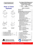
How To Use This Manual
Tab
Index
The manual is divided into twelve major sections
as shown above. Each section can be located
with the tabs on the right hand edge of the page
as shown in this picture. The first page of each
section is an index of the subjects covered in
that section. An alphabetical index of the whole
book is in Section 11.
i/ii
TM 10-3950-263-14&P-1
Operator's Manual
List Of Illustrations
TITLE
1-1
1-2
1-3
1-4
1-5
1-6
1-7
1-8
1-9
1-10
1-11
1-12
1-13
1-14
1-15
1-16
1-17
1-18
1-19
1-20
1-21
1-22
1-23
1-24
1-25
1-26
1-27
1-28
1-29
1-30
1-31
1-32
1-33
1-34
1-35
1-36
1-37
1-38
1-39
1-40
1-41
1-42
140 Ton FMC Link-Belt (R) Crane
Upper Machinery
Clutch Schematic
Shaft Schematic
Boom Lowering Planetary
Carrier Control
Transmission Shift Decal
Shifting Diagram
Machine Top and Side View
Bumper Outrigger Assembly
Outrigger Control Panel
Front Outrigger Box Removal
Outrigger Pin Removal System
Pin Remover Controls
Fluid Starting Aid
Upper Control Panel
Front Instrument Panel
Voltmeter Readings
Upper Controls
Master Clutch Control
Swing Lock Control
Swing Brake Control
Swing Control
Front Drum Control Lever and Brake
Rear Drum Control Lever and Brake
Brake Pedal Locks
Drum Rotation Indicators
Boom Hoist Control
Boom Hoist Limiting Device Override
Engine Throttle Controls
Hand Signal Chart
Wire Rope Capacity Chart
Counterweight Removal Controls
"AB" Upper Counterweight
Bumper Counterweight
Boom Foot Pin Removal System
Live Mast Control
Extending Or Retracting Live Mast
Lifting Sling Assembly
Lifting Arm Assembly
Lifting Assembly
Machine Tie Down
PAGE
1-2
1-4
1-4
1-5
1-5
1-7
1-10
1-10
1-11
1-11
1-12
1-13
1-14
1-15
1-15
1-16
1-17
1-19
1-20
1-21
1-21
1-22
1-22
1-23
1-23
1-23
1-24
1-24
1-24
1-25
1-26
1-27
1-28
1-28
1-29
1-30
1-31
1-31
1-33
1-33
1-34
1-34
2-1
2-2
2-3
2-4
2-5
2-6
2-7
2-8
2-9
2-10
2-11
2-12
2-13
2-14
2-15
2-16
2-17
2-18
2-19
2-20
2-21
2-22
2-23
2-24
2-25
Carrier Lubrication Chart
Upper Lubrication Chart
Attachment Lubrication Chart
Planetary Wheel Hub
Chain Case
Outrigger Sump Tank
Planetary Speed Reducer
Swing Bevel Gear Case
Reduction Shaft Bevel Gear Case
Air Box Drain Tank
Cleaning With Compressed Air
Cleaning Element with Water
Inspecting the Element
Oil Check and Fill - Item 1 (2-47)
Cooling System - Item 14 (2-51)
Turbocharger - Item 5 (2-52)
Tachometer Drive - Item 7 (2-54)
Air Cleaners - Item 8 (2-55)
Drive Belts - Item 9 (2-56)
Air Compressor - Item 10 (2-57)
Fuel Strainer and Filter - Item 13 (2-60)
Starting Motor - Item 15 (2-62)
Air Box Drains - Item 18 (2-65)
Radiator - Item 21 (2-67)
Alternator - Item 27 (2-71)
2-4
2-10
2-12
2-15
2-16
2-16
2-17
2-18
2-18
2-18
2-19
2-19
2-19
2-21
2-22
2-22
2-23
2-23
2-23
2-24
2-24
2-24
2-25
2-25
2-26
TITLE
2-26
2-27
2-28
2-29
2-30
2-31
2-32
2-33
2-34
2-35
2-36
2-37
Fan Hub - Item 31 (2-75)
Blower Screen - Item 33 (2-77)
Crankcase Breather - Item 34 (2-78)
Torque Converter - Item 40 (2-80)
Filter Mounting Upper Engine
Filter Mounting Carrier Engine
Typical By-Pass Filter Mounting
Spin-On Fuel Filter and Strainer
Water Characteristics
Heat Transfer Capacity
Coolant Inhibitor Chart
Coolant Freezing and Boiling Temperatures versus Antifreeze Concentration
PAGE
2-26
2-27
2-27
2-27
2-28
2-28
2-28
2-28
2-34
2-34
2-36
2-37
3-1
3-2
3-3
3-4
3-5
3-6
3-7
3-8
3-9
3-10
3-11
3-12
3-13
Carrier Assembly
Clutch Linkage
Carrier Clutch
Steering Mechanism
Front Wheel Alignment
Front Axle Assembly
Brake Assembly
Wheel Torque Procedure
Tire Inflation Chart
Rear Axle Assembly
Outrigger System Schematic
Test Gauge Assembly
Outrigger Throttle Control
3-1
3-2
3-2
3-2
3-3
3-3
3-4
3-4
3-5
3-5
3-6
3-6
3-7
4-1
4-2
4-3
4-4
4-5
4-6
4-7
4-8
4-9
4-10
4-11
4-12
Master Clutch Assembly
Swing Lock Assembly
Swing Lock
Swing Brake
Counterweight Remover Assembly,
Planetary Brake
Front and Rear Drum Brakes
Boom Hoist Brake
Clutch Assembly
Air Box Drains
Control Lever Adjustment
Chain Case With Adjuster
4-1
4-1
4-2
4-3
4-4
4-4
4-5
4-6
4-7
4-7
4-8
4-8
5-1
5-2
5-3
5-4
5-5
5-6
5-7
5-8
5-9
5-10
5-11
5-12
5-13
5-14
5-15
5-16
5-17
5-18
5-19
5-20
5-21
5-22
Machine With Basic 50-Ft. (15.24m) Boom
Working Area Definition Label
Boom Live Mast
Live Mast Used As Short Boom
Boom And Mast Foot Assemblies
Boom Backstop Assemblies
Main Pendants and Links
Deflector Roller Assembly
Deflector Roller Location
Boom Assembly - Step 1
Boom Assembly - Step 2
Boom Assembly - Step 3
Boom Assembly - Step 4
Boom Assembly - Step 1
Boom Assembly - Step 2
Boom Assembly - Step 3
Boom Assembly - Step 4
Inline Pin Tubular Boom Disassembly
Inline Pin Tubular Boom Assembly
Carrying Link Assembly
Carrying Boom Horizontal Over Rear
Carrying 50-Ft. (15.24m) Boom Over
Front With Gooseneck Links
16 Part Boom Hoist Reeving
Wrapping
Hammer and Block
Main Hoist Reeving, L.H. Drum Socket
5-1
5-2
5-2
5-3
5-4
5-4
5-5
5-5
5-5
5-6
5-7
5-7
5-7
5-8
5-9
5-9
5-10
5-11
5-12
5-13
5-14
5-15
5-23
5-24
5-25
5-26
HC238A
R783
5-17
5-17
5-18
5-19
1 of 2
iii
TM 10-3950-263-14&P-1
Operator's Manual
TITLE
5-27
5-28
5-29
5-30
5-31
5-32
5-33
5-34
5-35
5-36
5-37
Main Hoist Reeving, L.H. Drum Socket
Wire Rope Lay
Measuring Wire Rope Diameter
Wire Rope Inspection Report
Wire Rope Failure Chart
Uncoiling Wire Rope
Wedge Type Connections
Wire Rope Clip Installation
Securing Dead End Of Rope With A
Wire Rope Clip
Boom Angle Indicator
Boom Hoist Limiter
List Of Illustrations
PAGE
5-20
5-21
5-21
5-22
5-23
5-24
5-24
5-24
5-25
5-26
6-1
6-2
6-3
6-4
6-5
6-6
6-7
6-8
6-9
6-10
Auxiliary Generator Assembly
Bleeding the Fuel System
Standard Control Panel
Setting Gap
Governor Adjustment
Setting Valve Clearance
Checking Valve Clearance
Decompression Mechanism
Air Cleaner and Fuel Filter Maintenance
Oil Level, Valves, And Crankcase
Breather Maintenance
6-1
6-2
6-3
6-3
6-4
6-4
6-5
6-6
6-8
6-9
7-1
7-2
7-3
Hydraulic Power Supply
S-o-M System Filter
Relief Valve Assembly
7-1
7-2
7-2
10-1
10-2
10-3
Overload Warning System Nomenclature
System Cabling And Interconnect
Main Electronics Adjustments
10-1
10-2
10-4
2 of 2
iv
R783
TM 10-3950-263-14&P-1
Warranty
Standard Warranty Cable Cranes
FMC CORPORATION, CABLE CRANE & EXCAVATOR DIVISION is hereinafter called the COMPANY.
The products manufactured by the COMPANY, exclusive of used or re-built machinery or equipment, are subject to the
following warranty:
(A) Warranty.
"ALL of COMPANY's products are of high quality and are manufactured in conformity with the best commercial practices
in the various lines. The COMPANY warrants all products manufactured by it to be free from defects in material and
manufacture at the time of shipment for six (6) months from date of shipment or 1000 hours of operation, whichever shall
occur first. The COMPANY will furnish without charge, f.o.b. its factory, replacements for such parts as the COMPANY
finds to have been defective at the time of shipment, or at the COMPANY's option, will make or authorize repairs to such
parts, provided that, upon request, such parts are returned, transportation prepaid, to the factory from which they were
shipped.
"This warranty shall not apply to any product which has been subjected to misuse; misapplication; neglect (including but
not limited to improper maintenance); accident; improper installation, modification (including but not limited to use of
unauthorized parts or attachments), adjustments, or repair. Engines, motors, and any accessories furnished with the
COMPANY's products, but which are not manufactured by the COMPANY, are not warranted by the COMPANY but are
sold only with the express warranty, if any, of the manufacturers thereof. THE FOREGOING IS IN LIEU OF ALL OTHER
WARRANTIES, WHETHER EXPRESS OR IMPLIED (INCLUDING THOSE OF MERCHANTABILITY AND FITNESS OF
ANY PRODUCT FOR A PARTICULAR PURPOSE), AND OF ANY OTHER OBLIGATION OR LIABILITY ON THE PART
OF THE COMPANY.
(B) Limitation of Liability.
"It is expressly understood that the COMPANY's liability for its products, whether due to breach of warranty, negligence,
strict liability, or otherwise, is limited to the furnishing of such replacement parts, and the COMPANY will not be liable for
any other injury, loss, damage, or expense, whether direct or consequential, including but not limited to loss of use,
income, profit, or production, or increased cost of operation, or spoilage of or damage to material, arising in connection
with the sale, installation, use of, inability to use, or the repair or replacement of, the COMPANY's products.
The COMPANY reserves the right to make alterations or modifications in their equipment at any time, which, in their
opinion, may improve the performance and efficiency of the machine. They shall not be obliged to make such alterations
or modifications to machines already in service.
Any operation beyond rated capacity expressly prohibited in the operating instructions or safety manual furnished with the
machine, or any adjustment, or assembly procedures not recommended or authorized in the operating or service
instructions shall void such warranty.
Special Provisions
The standard machine warranty is modified by special provisions in solicitation DAAE07-80-B-5230.
J07 EQUIPMENT WARRANTY
J.7.1 Definitions
Acceptance. The word "acceptance" as used herein means the execution of the Acceptance Block and signing of a DD
Form 250 by the authorized Government representative.
Supplies. The word "supplies" as used herein means the end item and all parts and accessories thereof, furnished by the
contractor, and any related services required under this contract. The word does not include technical data.
J.7.2 Warranty. Notwithstanding inspection and acceptance by the Government of the supplies furnished under the
contract or any provision of this contract concerning the conclusiveness thereof, the contractor hereby warrants that the
supplies are free from defects in design, material, and workmanship and will conform with the specifications and all other
requirements of this contract for a period of 15 months from date of acceptance, as shown on the Material Inspection and
Receiving Report (DD Form 250), or 1500 hours of operation, whichever occurs first. Equipment designated as
Production Samples shall be treated as equipment delivered
1 of 5
v
TM 10-3950-263-14&P-1
Warranty
at the time as the production units. If a Safety Recall defect occurs during equipment warranty period, the contractor
agrees to extend the term of the warranty by the period of time equal to the time period required to make necessary safety
defect corrections. Additionally, to the extent of the contractor or his supplier(s) provide to commercial customers a
greater warranty for the supplies furnished therein, the contractor hereby likewise provides such greater warranty to the
Government. To the extent the terms of such greater warranty are inconsistent with or conflict with this warranty, the
provisions of this warranty shall govern.
J.7.3 Remedies.
J.7.3.1 New Replacement Supplies. With respect to defective supplies, wherever located, the warranty shall include the
furnishing, without cost to the Government, F.O.B. contractor's plant, branch or dealer facility, or F.O.B. original CONUS
destination, or F.O.B. US Port of Embarkation, at the Government's option, new supplies to replace any that prove to be
defective within the warranty period.
J.7.3.2 Corrective Action Options. In addition, the Government shall have the option (a) to return the equipment or parts
thereof to the contractor's plant, branch or dealer facility for correction, or (b) to correct the supplies itself. When the
Government elects to return the equipment or parts to the contractor's plant, branch or dealer facility, the cost of labor
involved in the correction of the defective supplies shall be borne by the contractor. When the equipment or parts thereof
are returned to the contractor for correction, the contractor shall bear all transportation costs to the contractor's plant and
return. With respect to defective supplies, when the Government elects to correct them itself, the cost of labor involved in
the correction of defects shall be borne by the Government. If the Government requires the assistance of Contractor
personnel in disassembly/reassembly of items removed in connection with repair or replacement of defective parts, the
Contractor will be reimbursed for labor at a rate to be negotiated between the Contracting Officer and the Contractor at
the time of repairs.
J.7.3.3 Notification. If the Government elects to have warranty repair or replacement performed by the contractor, the
Government shall deliver the parts or equipment to contractor's local facility or dealership for warranty corrective repair or
replacement. If the Government elects to effect warranty repairs or replacement itself, the contractor shall be notified in
writing of repairs required under the warranty within 30 days after discovery of the defect. Within 10 days after receipt of
such notices, the contractor shall submit to the Contracting Officer a written recommendation as to the corrective action
required to remedy the defect. In any event, the Contracting Officer may, upon the expiration of the 10 day period set
forth above, proceed with correction or replacement as set forth in the paragraph, Remedies, above, and the contractor
shall, notwithstanding any disagreement regarding the existence of a breach of warranty, comply with the Contracting
Officer directions related to such correction or replacement. After the notice, but not later than 30 days after receipt of the
contractor's recommendation for corrective action.
The Contracting Officer will, in writing, notify the contractor of the parts used by the Government in repair or replacement
and all other costs or expenses required for Government correction of warranty defect as set forth in the paragraph,
Remedies, above. The contractor shall respond within 30 days after receipt of this notice, of his intention to furnish
identified replacement parts and/or cost reimbursements to the Government. In the event it is later determined that the
contractor did not breach the warranty in paragraph, Warranties, above, the contract price will be equitably adjusted
pursuant to the terms of the "Changes" clause of the contract. Failure to agree to such an equitable adjustment or upon
any determination to be made under this clause shall be a dispute concerning a question of fact within the meaning of the
"Disputes" clause of this contract.
The Contractor shall furnish with his proposal a listing of distributors, dealers, and franchise outlets where warranty claims
may be exercised.
J,7.4 Decalcomania. A synopsis or simplified summary of the warranty coverage and its implementation will be printed
on a decalcomania approximately 3" x 4" and shall be mounted in view of the operator as near as possible to the center of
the instrument panel of each vehicle. On those vehicles requiring concealed markings and registration numbers said
decalcomania shall be placed in a readable position on the engine side of the firewall.
J.7.5 Rights. The rights and remedies of the Government provided in this clause are in addition to and do not limit any
rights afforded to the Government by any other clause in the contract.
Exceptions To Warranty
The following supplies are not covered under the 1500 hour or 15 month warranty: (1) Tires (2) Batteries (3) Light Bulbs
(4) Windshield wipers (5) Electrical Wires (6) Lubricants (7) Filters.
2 of 5
vi
TM 10-3950-263-14&P-1
Warranty
Preparation Of Warranty Claims
(1) Use warranty claim no. 531 for all claims over $25. These forms are available at no charge from the factory.
(2) Claims less than $25.00 will not be processed.
(3) Campaigns - A $25.00 minimum will be paid on all claims identified as a campaign and listing the campaign only on
the individual warranty claim.
(4) Delivery and applicable follow-up reports must be on file before warranty consideration will be given.
(5) Warranty Claim must be typed and mailed to the manufacturing division where the particular machine was
manufactured no later than 45 days after work is completed. Do not type on the reverse side of the warranty claim
form. If additional space is required on the warranty claim form, attach an additional sheet.
(6) The upper right hand corner of the claim must be completely and correctly filled out. Information about description of
the job must also be furnished.
(7) Under Section 1 and 2 of the warranty claim, explanation must be given covering problem as diagnosed and
corrective action taken. The statement "installed or replaced" will not be accepted as a satisfactory explanation of
the diagnosis of problem and corrective action taken. Neither will the statement making reference to a previous
report be accepted in lieu of information correctly filled out explaining the problem and correct action taken.
(8) Section 3 entitled "Name of Part(s) That Failed or Caused Failure" must be completely filled out to enable the factory
to determine disposition of defective parts. The serial number of the replacement part is also required to ensure
future warranty of the part replaced.
(9) Section 4 of the claim entitled "Other" is reserved to list things not provided for elsewhere on the form. Examples: A
freight bill, outside purchase of parts, outside labor for machine shop, etc. A copy of the paid invoice must
accompany each claim.
(10) Section 5 is to list item number of part, description of part, quantity of part, invoice number and cost covering parts
claimed.
(11) If part or parts were supplied from your "stock", type the word "stock" in the invoice section provided in Area 5.
(12) If parts were ordered where a 5 or 10% added cost was assessed for emergency shipment, a copy of the invoice
must be attached.
(13) If a large group of parts were ordered from the factory for warranty repair, a legible copy of the FMC invoice attached
in lieu of filling out Section 5 if preferred.
(14) If an incorrect FMC part number is listed or a part claimed that cannot be identified, it will be eliminated from the
claim and will not appear on the credit memo.
(15) Section 6 and 8 are reserved for factory use only. Do not enter any information in these areas.
(16) Section 7 under labor, type hours only.
Returning Defective Or Failed Parts To The Manufacturing Division
(1) Do not send defective parts to the factory. Hold all defective parts until information is received as to their disposition.
If and when the parts are needed by the manufacturing division, the manufacturing division will forward instructions
wither verbally or in writing and/or both. In all cases an A.T.R. number (Authorization to Return and Authorization to
Receive) will be assigned with shipping instructions.
A.T.R. 87 - - - is used by the Bowling Green plant.
FMC Corporation
Crane & Excavator Division
U.S. 31. W. South
Bowling Green, Kentucky 42101
The Receiving Departments have orders not to accept any shipment of warranty parts without an A.T.R. number
clearly displayed on all parts, shipping cartons, tags, bills of lading and other papers required by transportation
companies.
If the part to be returned is a large item that cannot be crated (Example: boom sections, large hydraulic cylinders,
frames, counterweights, etc.) it will be necessary to have the A.T.R. number legibly marked or painted with some
waterproof marking device. If it is a part that is apt to be rolled over, it is required that the number be marked on two
or more sides of the component.
(2) Parts must be returned in clean condition. Hydraulic parts must be sealed to prevent contamination. Any parts
received without covering port plugs, etc., will not be inspected or forwarded to the vendor as vendors refuse any
warranty consideration of hydraulic components not properly protected.
(3) Shipping of parts for more than one claim in one shipment is discouraged. However, if for some reason or other, this
must be done than each individual part must be identified by item number, claim number and A.T.R. number.
3 of 5
vii
TM 10-3950-263-14&P-1
Warranty
Submitting Of Warranty Claims
(a) Prepare claim as outlined under "PREPARATION OF WARRANTY CLAIMS".
(b) Distribute copies as follows:
Copy #1 White
Copy #2 Yellow
Copy #3 White
Copy #4 Pink
Copy #5 Green
Copy #6 Blue
(
(
(
(
(
(
Forward copies to the Manufacturing Division
responsible for the model involved. For your
assistance we are listing below the mailing
address of each of the models manufactured.
Government copy. Copy should be retained
for your records.
(c) You will be advised on the disposition of any alleged defective parts.
(d) Approximate time for processing claims that are within the time frame of normal warranty will fall in the following
categories:
(1) If material is not required for inspection, the claim will be accepted or rejected within 45 days of receipt of the #3
copy. The Government will assume the responsibility for destroying and scrapping related parts under the
direction of the Warranty Supervisor.
(2) If material is required for inspection, the claim will be accepted and credit issued within 45 days of receipt of the
part or parts at the factory or a designated location. If inspection reveals the part or parts were not defective, the
factory will re-invoice the Government to cancel the credit previously issued.
(3) Government will be notified by phone followed by confirming letter with shipping instructions for alleged defective
parts. If parts not received within 3 days a follow-up letter will be sent to distributor. If parts not received within 30
days after follow-up letter mailed, warranty claim will be cancelled.
(4) A disputed warranty settlement must be presented in writing to Construction Equipment Distribution Operation,
2800 Lakeside Drive, Bannockburn, Illinois 60015, Attention: Service Department, no later than 45 days after the
warranty claim status report is dated.
If the Government does not reply to FMC within the 45 day time frame, the warranty claim will not be opened to any
further discussion at a later date.
Listed below are the mailing addresses and models for the Manufacturing Division. Direct claims to the attention of the
Warranty Departments.
FMC Corporation
Crane and Excavator Division
Box 9500
Bowling Green, Kentucky 42101
Campaign Procedures (Safety Recall)
A. Labor compensation for announced factory modification and retrofits implemented by CCED.
(1) FMC will compensate the Government 100% of its charge out rate which must be on record with the company at
the time the claim is received, for performance of work related to the campaign.
(a) If FMC has established the work time required to effect the campaign, only the time so established will be
recognized in establishing the amount of the claim.
(b) If FMC has not established the hours required to effect the campaign, the company will accept actual
documented time expended by the distributor, provided the time is reasonable and can be substantiated.
B. Travel Time - Per Diem
(1) FMC will compensate the Government at 100% of their charge out rate, on record with the company, for actual
travel time expended in the performance of campaign work up to a maximum of eight hours.
(2) The standard 10% add-on clause, as found in the warranty labor program, will not apply to computing the credit
amount on the warranty claim.
(3) In addition to travel time, a reasonable per diem will be allowed for living expenses. Per diem receipts must
accompany claim.
4 of 5
viii
TM 10-3950-263-14&P-1
Warranty
C. Overtime
(1) Overtime charges will not be accepted, unless agreed to by the company prior to the performance of the work.
D. Limits of FMC Responsibility
(1) FMC reserves the right to make alterations or modifications in their equipment at any time which in their opinion
may improve the performance and efficiency of the machine. FMC shall not be obligated to make such alterations
or modifications to machines already in service
(2) FMC will not be under obligation to credit the Government with the price of the new part or to reimburse the
Government for the labor cost for repairing or replacing defective part unless, within thirty (30) days of the date of
the campaign work performed, the Government submits a typewritten claim listing parts used and the FMC allotted
time provided in the campaign letter, or if FMC has not established the time, satisfactory proof of the time
reasonably expended in repairing or replacing the defective part.
(3) FMC will issue a minimum of $25.00 per claim.
(4) Claims which cover campaign work performed on more than one machine will not be accepted.
(5) The work must be completed within the time frame stated in the campaign agreement and campaign instructions.
If campaign work is not completed within the stated time frame, FMC assumes no responsibility for any damage
that might be incurred due to delay of campaign completion.
E. Requirements for Qualification
(1) The Government will utilize only qualified personnel in the performance of campaign work. These personnel must
have attended an authorized factory school on the particular product line within the past 18 months.
(2) The Government must maintain properly equipped service vehicles and shop facilities as dictated by general
industry standards.
(3) The Government must have any specialized material, equipment, and tools, required by general industry
standards.
(4) The Government must maintain a current and updated service library; including service manuals, bulletins, policy
handbook, parts books, and/or microfilm.
5 of 5
ix/x
TM 10-3950-263-14&P-1
VOLUME ONE
OPERATION AND MAINTENANCE
(Service Manual Is contained In Volume Two;
Repair Pars is contained In Volume Three)
TABLE OF CONTENTS
Section
0
00
1
2
3
4
5
6
7
8
9
10
11
Page
Operating Safety ................................................................................... 0-1
Introduction ........................................................................................ 00-1
Operating Instructions ........................................................................... 1-1
Preventive Maintenance and Lubrication ................................................ 2-1
Carrier Adjustments .............................................................................. 3-1
Upper Adjustments ............................................................................... 4-1
Crane Attachment ................................................................................. 5-1
Auxiliary Generator Assembly ................................................................ 6-1
Speed-O-Matic Control System .............................................................. 7-1
Troubleshooting Procedures .................................................................. 8-1
Specifications and General Information .................................................. 9-1
Overload Warning System.................................................................... 10-1
Appendixes ..........................................................................................A-1
Alphabetical Index ............................................................................... 11-1
0-31
1-34
2-38
3- 7
4- 8
5-27
6-12
7- 2
8- 6
9- 5
10- 6
A-72
11- 2
1 of 1
xi/xii
TM 10-3950-263-14&P-1
OPERATOR'S MANUAL
SECTION 0 - OPERATING SAFETY
General
This section is intended to cover operating practices
on both hydraulic and non-hydraulic machines.
Correct operating practices for both types are
similar, but different problems will arise on each type
of machine. For this reason, there is a paragraph in
this section on hydraulic/machine safety. The other
sections, for the most part, apply to both types of
machines.
Read this every day - someone's life may depend on
it, maybe your own.
When a crane or excavator is maintained and used
properly, it can be a safe, highly useful piece of
equipment, but as with many commonly used things
such as a lawn mower, a motor boat, or even a kitchen
knife, if not used properly it can be dangerous.
Think safety. You, the operator, are in charge of an
important piece of equipment. It is very important that
you know what it can do. It is also important that you
know what it should not do. No set of instructions can
anticipate all of the situations you will run into. The rules
given here cover general usage, and some of the more
specific cases. If conditions arise not covered by these
rules, consult the manufacturer. A phone call may save
someone's life.
Reference Material
1
2
PCSA (Power Crane and Shovel Association
Construction
Industry
Manufacturers
Association), 111 E.
Wisconsin Avenue,
Milwaukee, Wisc.
53202, standard No.
1,
"Mobile Power Crane and Excavator Standards",
contains a section on safety. Safety booklets on
crane and excavator operating safety are also
available from PCSA.
3
The Department of Labor, occupational Safety and
Health Administration, publishes safety and health
regulations and standards under authority of the
Occupational Safety and Health Act (OSHA). Its
address is "Occupational Safety and Health
Administration, U.S. Dept. of Labor, Washington,
D.C., 20210.
4
American National Standards Institute, (ANSI) C/O
The American Society Of Mechanical Engineers,
United Engineering
Index
Subject
General
Reference Material
General Safety Rules
Working Near Power Lines
Crane Boom Safety
Demolition Work
Excavator Safety
Carrier Operation
Crawler Operation
Hydraulic Machine Operation
Wire Rope Strength Chart
Hand Signal Chart
Page
0-1
0-1
0-2
0-6
0-9
0-22
0-23
0-24
0-27
0-28
0-31
1-26
Additional material on safe operation is available
from several sources. FMC strongly recommends
that crane/excavator users obtain this information:
SAE - Society of Automotive Engineers, Inc., 400
Commonwealth Drive, Warrendale, Pa.
15096,
publishes a list called "Safety Considerations For
The Operator", SAE J153, in their "Recommended
Practices Manual".
0-1
TM 10-3950-263-14&P-1
OPERATOR'S MANUAL
SECTION 0 - OPERATING SAFETY (CON'T)
Center, 345 East 47th Street, New York, N.Y.
10017 includes standards for safe operation,
inspection, and maintenance in their ANSI B30.5 1968 and B30.15 - 1973.
General Safety Rules
1
Read the operator's manual and heed it.
manual contains Important Information.
The
2
Whenever an operator leaves the control station
for any reason, the following must be done:
a Lower the bucket, grapple, load, etc. to the
ground.
b Engage the swing lock. Disengage the master
clutch. Shut off the engine. Engage the park
brake (tire mounted) or travel brakes (crawler
mounted).
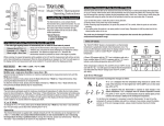
c Never depend upon a brake to suspend a load
unless the operator is at the controls, alert and
ready to handle the load.
Brake slippage,
vandalism, mechanical malfunctions, could
cause the load to drop if left in the air
unattended.
Fig. 1
Never leave a load in the air. It may fall.
Note: The brake pedal locks are intended to allow
the operator to rest his legs when suspending a load
for a short period of time, but the operator must
remain in his seat with his feet on the pedals. Failure
to follow these instructions could lead to an accident.
3
4
0-2
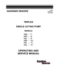
Fig. 2
An operator must not eat, read, or otherwise
divert his attention while operating a machine.
Remember - operating is a full time job.
Don't allow crane loads, bucket, grapple, etc. to
pass over people, or endanger their safety.
Remove all loose objects from load.
All nonoperating personnel should leave the immediate
area when machine is operating.
Don't let anyone hitch a ride.
5
Don't let anyone ride the hook block, bucket,
grapple, etc. These machines are intended to lift
objects - not people. They are not elevators.
TM 10-3950-263-14&P-1
OPERATOR'S MANUAL
SECTION 0 - OPERATING SAFETY (CON'T)
6
Be sure your work area is clear. Make sure you
have proper clearance for machine boom or load,
Don't swing, travel, hoist, or lower load, raise or
lower boom, extend or retract outrigger beams, raise
or lower jacks, without first making sure no one is in
the way. If your vision is obscured, locate a signal
man so you can see him, and he can see all areas
you can't. Follow his signals. Be sure you and the
signal man understand each others signals. (See
hand signal chart on back cover). Use the horn to
signal or warn. Make sure everyone on the job
understands signals before starting work.
Fig. 3
Watch your clearances
7
Inspect the machine daily.
Don't operate a
damaged or poorly maintained machine. Pay
particular attention to the clutches, brakes,
attachment, and wire ropes. If a component is worn
or damaged, replace it before operating. Remember
- parts are cheaper than people.
Be sure clutch and brake surfaces are clean and
dry. A small amount of clutch or brake slippage may
dry out wet linings. Avoid excessive heating; it
shortens lining life. If oil or grease gets on linings,
clean them immediately with a nonflammable, low
toxicity solvent. If linings are saturated, replace
them.
Fig. 4
Don't work with worn or damaged rope.
OSHA (Occupational Safety And Health Act)
regulations state, "a thorough inspection of all ropes
shall be made once
0-3
TM 10-3950-263-14&P-1
OPERATOR'S MANUAL
SECTION 0 - OPERATING SAFETY (CON'T)
available from your distributor. Some of the steel
used in booms is a special type which can be ruined
by wrong repair procedures. If a chord is damaged
or bent, even a small amount, Don't Use It. Don't try
to repair it. Chords are so vital to the strength of the
boom that it is not practical to attempt repairs.
a month and a full written, dated and signed report
of rope condition kept on file where readily
available". Replace any worn or damaged rope.
Pay particular attention to boom hoist ropes and
pendants. Check end connections (pins, sockets,
wedges, etc.) for wear or damage.
8
Don't let the load or bucket hit the boom. Don't
let the boom rest on or hit against a building or
any other object. A dented
Fig. 6
Boom extension nomenclature.
If the boom, mast, gantry, etc. are struck or
damaged, by anything, stop. The loading on a
boom increases as the boom is lowered; therefore a
damaged boom or boom suspension system may
collapse during lowering. Use a helper crane to
assist in lowering a damaged boom.
Fig. 5
9
Don't let the load hit the boom.
or damaged boom may result, which will weaken the
boom. If the damage is severe, the boom may
collapse. If a lattice or diagonal bracing member is
broken or cracked, replace it. If bent, straighten it.
Important - Detailed information on boom repair is
0-4
Be sure the boom hoist pawl is always engaged
except when lowering the boom. Don't rely on the
boom hoist brake alone to hold the boom. Wear,
improper adjustment, water or oil on linings, and
other factors may reduce the ability of the
TM 10-3950-263-14&P-1
OPERATOR'S MANUAL
SECTION 0 - OPERATING SAFETY (CON'T)
brake to hold the boom.
10 Always replace protective guards and panels
before operating machine.
11 Always wear hard hats, safety glasses, steel toe
shoes, and any other safety equipment required
by local or job conditions on regulations.
personnel in proper use of the extinguisher. Check
periodically to make sure It is fully charged and is in
working order.
15 Never tamper with safety devices. Keep them in
good repair and properly adjusted. They were put
on the machine for your protection.
16 Don't smoke when fueling, or fuel up near an
open flame. Keep the nozzle in contact with the
filler neck to prevent static electric sparks. Shut off
the engine when fueling.
Fig. 7
Dress properly on the job.
12 Never get on or off a machine In motion. Use
both hands when climbing onto a machine. If a
ladder is provided, use it. Be careful when walking
on track shoes. They may be slippery and cause a
fall.
13 Keep your machine clean, In good repair, and in
proper adjustment. Oil or grease on the decks
may cause falls. Improper adjustments can lead to
machine damage, load dropping, or other
malfunction.
14 Keep a dry chemical or carbon dioxide fire
extinguisher of 5BC rating or larger In the cab or
In the Immediate vicinity of the machine at all
times.
Instruct all operating and maintenance
17 Before performing repairs or adjustments, lower
attachment to the ground, or onto blocking. Be
sure of safe footing before standing or walking on
boom or jib. Use a ladder, planking or lift platform to
prevent falls. On truck mounted machines, lower
machine off the outriggers. If this is not possible,
block securely under the outrigger beams. Lock the
starter, or remove battery cables so machine can't
be started. Remove ignition key. Post warning
signs in cab so no one will try to start the engine.
18 Always reduce pressure in hydraulic system to
zero before working on any part of the system.
Work control levers back and forth with engine shut
down to reduce the pressure to zero.
19 Keep fingers, feet, and clothing away from
sheaves, drums, and ropes unless the machine
is shut down and everyone knows what you are
doing. Never place a hand on lines when climbing
to the top of the machine. A sudden movement may
pull them into the drum or sheaves.
20 When checking battery level, use a flash light not an open flame. Battery gas is explosive. If the
battery explodes you may get acid in your eyes,
which may cause blindness. Don't check battery
0-5
TM 10-3950-263-14&P-1
OPERATOR'S MANUAL
SECTION 0 - OPEATING SAFETY (CON'T)
charge by shorting across posts. The resulting
spark could cause the battery to explode. Check
with a tester or hydrometer. Don't smoke near
batteries, especially when they are being charged.
22 Pinch points, which result from relative motion
between mechanical parts can cause Injury.
Keep clear of rotating upper or moving parts.
Fig. 9
Be careful when removing radiator caps.
Fig. 8
Never use an open flame to check a battery.
When using jumper cables to start an engine be
sure to connect negative post to negative post, and
positive post to positive post. Always connect the
two positive posts together first, and the two
negative posts last to prevent a spark when the
cables are connected. This spark could cause the
battery to explode.
21 When working Inside a building, check clearance
to avoid a collision. Check load limits on floors or
ramps so you won't crash through. Always check
work areas for dangerous features. Don't operate
close to an overhang or deep ditch. Avoid caving
edges, falling rocks, slides, etc. Never park machine
where a bank can fall on It, or it can fall In an
excavation. Don't park where rain can wash out
footings.
0-6
23 Use extreme caution when removing radiator
caps, drain plugs, grease fittings, hydraulic
pressure caps, etc. They may fly off and hit you, or
you may be burned by hot oil, water or steam.
24 Always wear safety glasses when drilling,
grinding, or hammering on metal. If you do not
wear safety glasses flying chips may Injure the eyes.
Working near power lines
1
All electrical power lines are dangerous. Contact
with them, whether insulated or not, can cause
death or injury. When operating near power lines,
the best rule is to have the power company cut off
the power and ground the lines. However, in some
cases, you will be unable to have the power cut off.
Follow these rules whether the power is cut off or
not.
a Be alert - you are working around conditions
which can cause death.
b Keep all parts of the machine - fall lines, hook
block, and load - at least
TM 10-3950-263-14&P-1
OPERATOR'S MANUAL
SECTION 0 - OPERATING SAFETY (CON'T)
c
d
15 ft. (4.75m) from the line, or other distance
specified by TB 385-101. Slow down machine
operation.
Assume that every line is "hot".
Appoint a reliable person equipped with a loud
signal (whistle or horn) to warn the operator
when any part of the machine or load moves
near the power line. This person should have
no other duties while the machine is working
around the power line.
f
The use of boom point guards, proximity
devices, insulated hooks, or blocks, or swing
limit stops do not assure safety. Even if codes
or regulations require the use of such devices
you must follow rules listed here. If you do not
follow them, the result may be serious injury or
death. The following illustrations portray some
of the limitations of the devices.
Fig. 11
Fig. 10
Even though crane equipped with insulating link and
boom peak guard. In this situation, the man is not
protected.
Stay away from power lines.
e
Warn all personnel of danger.
Allow no
unnecessary person in the area. Don't allow
anyone to lean against or touch the machine.
Don't allow sling men or load handlers to hold
load, lines, or rigging gear unless absolutely
necessary. Use dry hemp or dry plastic ropes
as tether lines. Make certain everyone stays 15
ft. (4.75m) away from the load, or such distance
as required by applicable code.
g
Grounding the machine may increase the
danger. Popr grounding such as a pipe driven
into the ground, gives little or no protection. In
addition, a grounded machine may strike an arc
so heavy that a live line may be burned down.
This could cause the machine and the area
around it to be electrified.
0-7
TM 10-3950-263-14&P-1
OPERATOR'S MANUAL
SECTION 0 - OPERATING SAFETY (CON'T)
Fig. 12
Crane equipped with both an insulating link and an
insulating boom point guard
Fig. 14
Crane equipped with proximity device. Shaded area
shows sensitivity zone with probe near boom peak
and adjusted for a 10-foot (3.04m) clearance.
Contact can be made outside this zone by the fall
lines, hoist ropes, gantry, cab, boom, etc. In such
cases, the warning will not sound until the machine
Is electrified and deadly.
Fig. 13
Crane equipped with proximity device.
Shaded area shows "sensitivity zone" with full boom
length sensor used, and adjusted for 10-foot (3.04m)
clearance. Contact can be made outside this zone
by the fall lines, hoist ropes, gantry, cab, etc. In
such cases the warning will not sound until contact
is made, and the machine is electrified and deadly.
0-8
Fig. 15
Grounding the machine to a pipe driven into the
ground gives little or no protection.
h
When operating near radio or T V. transmitting
stations, high voltage can be induced in metal
parts of cranes, or in their loads. This can occur
even
TM 10-3950-263-14&P-1
OPERATOR'S MANUAL
SECTION 0 - OPERATING SAFETY (CON'T)
if the machine is some distance from the
transmitter or antenna.
Painful, dangerous
shocks may occur. Consult trained electronic
personnel before operating machine is begun to
determine how to avoid hazards.
2
3
When using a magnet:
What do you do if a power line is touched by
machine or load?
a. Lifting magnet generators produce voltages in
excess of 200 volts and present an electrical
shock hazard. Only trained personnel should
work on the magnet, controller, or wiring. Never
open the controller door with the generator
running.
a. Keep cool - think - a mistake can kill someone.
b. Do not let workmen touch magnet or load.
b. Warn all personnel to keep clear.
c. Do not let workmen get between magnet and a
metal object.
c. If machine will still operate, try to move it away
from contact. You, the operator, are reasonably
safe in the cab unless the machine is on fire or
an arc is cutting through the cab near you.
d. Move away from contact in reverse to that which
caused the contact. Example: If you swing left
into wire, swing to the right to break contact.
Remember once an arc has been struck, it will
stretch out much further than you think before it
breaks. Keep moving away from the line until
arc breaks.
e. When arc breaks, continue moving until you
are at least 15 Ft. (4.57m) away (or as
specified by local code.). Stop the machine.
Thoroughly Inspect machine for damage.
Repair any damage before further use.
f. If you cannot disengage from the line, and
machine is not on fire or no arc is cutting
through the cab, stay in your seat until power
line can be shut off.
g. If you must leave the machine, Don't step off.
Leap From The Machine as far as you can.
d. If necessary to position a load, use a dry,
wooden stick.
e. Open magnet disconnect switch at magnet
control panel before connecting or disconnecting
leads.
Crane Boom Safety
1.
The operator, supervisor, or person in charge of
the load must observe the following rules.
a. Loads must be well secured before lifting. Be
sure that the rigging can't slip off or pull away
from the load, or get out of position on the load.
Be sure load is rigged so it won't fall over.
b. Chains and slings must be of adequate size, in
good condition, and not twisted around each
other.
c. The load must not catch on an obstruction when
lifting or swinging. Be sure load, fall lines or any
other part of machine does not snag or strike
any obstruction.
d. Avoid sudden starts and stops. Lift carefully,
swing gently, brake smoothly, lower and set
loads carefully. Jerking the load, swinging and
plugging the swing clutches roughly,
0-9
TM 10-3950-263-14&P-1
OPERATOR'S MANUAL
SECTION 0 - OPERATING SAFETY (CON'T)
lowering the load rapidly, and slamming on the
brakes, will put shock loadings and possible side
loadings on the boom. Cowboys sometimes use
rough treatment to break horses rough treatment
can also break a machine. Unnecessary abuse
labels the operator as a beginner.
Be a
professional.
load (2000 -3000 lbs.) (907-1360 kg) a few Inches
above the ground. If machine is level, fall lines will
hang directly between the boom feet, as you face
the boom. Now swing over the side. The lines
should still hang directly between the boom feet.
Don't use this method on a windy day.
Fig. 16
Make sure load doesn't get caught
e. Never wrap the hoist line around the load.
Never use discarded, worn, or damaged rope for
slings. It may break and drop the load.
f. The machine must be level before making a lift.
Use levels if the machine is so equipped. If not
use a good carpenter's level placed on a smooth
horizontal surface on the upper or lower frame.
Remember a 3 degree side tilt can reduce
capacities by 50% or more.
The hook block and fall lines can be used as a
"plumb bob" to level a machine, Fig. 17. Pick up
a compact
Fig. 17
Level the machine
2
0-10
The hoist line must be vertical when
TM 10-3950-263-14&P-1
OPERATOR'S MANUAL
SECTION 0 - OPERATING SAFETY (CON'T)
over the side on rubber. The lean will increase
operating radius so the load will swing outward when
it clears the ground. This outswing is dangerous to
anything in the path of the load and because of the
increase in load radius may overload the machine.
To overcome this outswing, boom up as the load is
lifted so fall lines remain vertical. When setting the
load on the ground, lower boom after load touches
down to avoid hook block swing when it is unhooked
from load, or the boom contacting the boom
backstops.
starting to lift. If not, load will swing in, out, or
sideways when lifted from the ground.
3
When swinging a load from over end to over
side, the lean described above will increase .
This is especially noticeable when operating on tires.
Since tilt acts to increase load radius, it must be
compensated for when swinging the load. Swing
slowly. Change boom angle (Raise or lower boom),
while swinging, to maintain a constant radius, and
prevent inswing or outswing of load. If not, a
dangerous condition may result.
4
Know your load. Don't try to guess or estimate
the load. Use a scale weight, carefully calculated
weight, a hook scale, or a load indicating system.
Remember the weight you are lifting includes the
weight of any lifting slings, or gear, the hook block,
and any overhaul weights. If picking off the boom
with the jib installed, the weight of the jib and rigging
must also be considered part of the load. The total
load weight must never exceed the rated capacity of
the machine, as listed on the capacity chart, for the
position, boom length, load radius and condition of
operation being used.
Fig. 18
Effect of side tilt
When picking a heavy load, machine will lean
toward the boom. This is caused by elasticity of
the machine and the boom. The lean is more
noticeable when picking
0-11
TM 10-3950-263-14&P-1
OPERATOR'S MANUAL
SECTION 0 - OPERATING SAFETY (CON'T)
Remember - capacity chart ratings are based on
ideal conditions:
a
b
c
d
e
c
d
e
f
g
Standing on firm, level surface
Calm wind
No side loads or outswing of load
Good visibility
Machine in A-1 condition and equipped as when
leaving the factory
Hazardous surroundings
Inexperienced personnel
Poor visibility
Fragile loads
Machine in poor condition
When in doubt, don't take a chance. Reduce
ratings more than you think you need to.
Avoid working a machine in high winds. If you
must work in a wind, reduce capacities considerably
below those shown on the capacity chart. Wind
blowing against the load and the boom produces a
side load on the boom and reduces its capacity.
When lifting large loads such as building panels in a
wind, the movement of the load may pose a danger
to workmen or building structures. Outswing of a
load will increase load radius, and may overload the
machine.
This could lead to boom failure or
machine tipping.
5
Don't operate at radii and boom lengths where
the capacity chart lists no capacity. Don't use
longer booms or jibs than listed on the chart.
Any of the above can tip the machine over, or cause
boom and/or jib failure.
6
Keep the load lines as short as possible to
prevent excessive swinging.
Always use the
shortest boom length which will do the job.
Remember, the shorter the boom, the stronger it is.
7
Watch out for centrifugal force when swinging a
load. Swing gently. Cen-
Fig. 19
Know your load
When such conditions cannot be attained, loads
being handled must be reduced to compensate.
The amount loads are reduced depends upon how
good, or how poor, the actual operating conditions
are. It is a matter of judgement and experience.
Some factors which may require reduction of loads
below listed ratings are:
a
b
0-12
Soft or unpredictable supporting surfaces
Wind
TM 10-3950-263-14&P-1
OPERATOR'S MANUAL
SECTION 0 - OPERATING SAFETY (CON'T)
Fig. 20
Watch out for centrifugal force
trifugal force tends to increase load radius. This
increase in radius could overload the machine and
cause machine damage and tipping. When stopping
the swing, overswing of the load can side load the
boom. The use of a tagline is recommended to
control this force.
8
Know the load radius. Don't guess it. Determine
radius by using the boom angle indicator, the boom
length, and the capacity chart, or measure It with a
steel tape.
Remember radius Is the horizontal
distance from the centerline of rotation of the upper
to the center of gravity of the load when the load is
hanging free.
9
Know the boom length. Don't guess. Use of an
incorrect boom length can cause an accident.
10 Use at least the number of parts of hoist line
specified in the wire rope capacity plate to
handle the load. In case your machine Is not so
equipped, one is included on page 31. Local codes
may require more parts of line than shown. Check
code requirements and use them where applicable.
Use special care when handling loads on single part
line with boom at a short radius. This Is especially
Important when hoist line is off rear drum. The
boom may be whipped back over machine. In single
line operation, make sure Angle A is always greater
than Angle B. (See Fig. 21 ).
11 Test the hoist brake by raising the load a few
inches and holding. It should hold easily. It takes
more brake to hold a load in the air when the drum
Is full of rope, than a few inches above the ground
with only one wrap on the drum.
12 Don't pull sideways on the boom, not even a
little bit. Lift straight up on every load. Moving
trucks, rail cars, barges, or
Fig. 21
Load Radius
0-13
TM 10-3950-263-14&P-1
OPERATOR'S MANUAL
SECTION 0 - OPERATING SAFETY (CON'T)
anything else by pulling sideways with the hoist line
Is liable to buckle the boom. It may also damage the
swing mechanism. Pulling sideways on a boom set
at a high angle can turn the machine over sideways.
pontoons as this reduces stability. Remember there
are tremendous loadings on pontoons and blocking,
the weight of the entire machine plus any load.
Fig. 22
Never use a boom to pull loads sideways
13 Never move a crane away from the load while
handling near capacity loads. Due to Ioad inertia
(weight) the load will tend to stay in position when
the machine starts to move, and then will swing in
toward the machine. The inertia effect will tend to
increase load radius and decrease stability. This
could lead to boom failure or machine tipping.
14 When operating on outriggers, the beams must
be fully extended. Jacks must be extended so tires
are clear of ground, and machine is level. Be sure
that blocking or pontoons are set on firm surface,
adequate to support the blocking or pontoon loading
without settling, slipping, or collapse. Blocking or
matting under pontoons must form a smooth level
surface under the entire pontoon. However, do not
also block under outrigger beams inside of
Fig. 23
Use of outriggers
When blocking or matting under pontoons, be sure
that each pontoon is supported fully no unsupported
pontoon area is permissible. Be sure pontoons are
on a smooth surface. Rough surface, rocks, etc.
under pontoon will cause unequal loadings, may
puncture it, and cause collapse.
Capacities are based on outriggers fully
extended.
Working with outriggers partially
retracted will reduce capacities and machine stability
considerably and may cause an accident. If it is
absolutely necessary to operate a machine with
outrigger
beams
partially
retracted,
reduce
capacities to those shown on the chart for "on
rubber". Remember the machine must be level.
Avoid working with only rear outriggers
0-14
TM 10-3950-263-14&P-1
OPERATOR'S MANUAL
SECTION 0 - OPERATING SAFETY (CON'T)
extended. If you swing over the side, the machine
may tip over, or the boom may be damaged from
side loadings because the machine is not level.
When working a machine with mechanical (nonhydraulic) outriggers, make sure the beams are
pinned in place, otherwise they can "creep in" while
operating, causing an unstable condition and
possibly tipping the machine over.
15 When using a boom length where retractable
gantry or live mast is required, be sure they are
fully extended and pinned in place.
16 When operating a lifting crane on crawlers,
where the tracks sink into the soil any noticeable
amount, use matting. Timbers used for matting
should be at least as long as the total width of the
lower and should be heavy enough to withstand
loadings without damage. Timbers should be close
together to form a solid platform.
Fig. 24
Use matting on soft ground
When lifting over crawler ends, block under track
ends so full support is provided where track leaves
the ground.
17 Don't alter any part of the machine. Additions to
or changes in any part of the equipment can create
loadings which the machine was not designed for.
Such changes may seriously affect the useable
capacities and make the entire capacity chart
invalid. Such changes can dangerously overload or
weaken critical parts and may cause disastrous
failure.
18 Don't operate over the front of a truck
Fig. 25
Working over the front can cause accidents
crane either on tires or on outriggers unless the
machine being used is rated over the front.
Lifting loads over the front can cause damage to the
carrier. Also the operator's vision may be obscured
by the front of the carrier.
If it is absolutely
necessary to work over the front, consult the factory
for special instructions and load ratings.
0-15
TM 10-3950-263-14&P-1
OPERATOR'S MANUAL
SECTION 0 - OPERATING SAFETY (CON'T)
19 Don't exceed the rated capacities of the machine
under any circumstances.
While a crane has
more stability when lifting over a corner (as
compared to straight over the side) the machine
capacity is not increased. Any time you exceed the
rated capacities listed on the capacity chart in the
operator's cab, you are overloading the machine.
Overloads can damage the machine and such
damage may cause failure and accidents.
20 Don't pick loads on main hoist and jib at the
same time, even if total load weight is within
machine capacity. Loads on the jib stress the
boom and drastically reduce its ability to handle
loads.
30 degrees (with respect to the boom) may cause jib
or suspension failure, and may cause dangerous
twisting forces in the boom.
22 Never use longer jibs than specified for your
machine. Never use a jib on a longer boom than
specified for your machine. Tipping may result.
23 Know how much counterweight is on the
machine.
Some capacity charts list different
capacities with differing amounts of counterweight.
Make sure you know how your machine is equipped
and use the correct column on the chart.
Fig. 27
Don’t add extra counterweight
Fig. 26
Don’t pick loads on main hoist and jib at
the same time
21 Don't work with jib angles greater than 30
degrees with respect to the boom. The greater
the angle, the less capacity the jib has. Working
with jib angles over
0-16
Don't increase the counterweight above that
specified. Don't add anything to the machine that
will act as additional counterweight. Remember that
anything which has weight, if carried behind
machine's tipping point, acts as counterweight.
Adding counterweight affects backward stability of
the machine, particularly
TM 10-3950-263-14&P-1
OPERATOR'S MANUAL
SECTION 0 - OPERATING SAFETY (CON'T)
when working over the side. It also encourages
overloading of the machine which can cause a
disastrous accident.
g. Keep all personnel clear of machine and load.
Be prepared to set load down quickly at any
time.
24 Traveling with a suspended load should be
avoided if possible. It is especially hazardous
when terrain is rough or irregular, on a side slope, or
in hilly areas. When traveling with a load, observe
the following rules:
h. When traveling up or down slopes keep the
upper facing downhill to reduce the tendency for
the boom to fall over the cab. If necessary to
face uphill, keep the boom down.
a. Tether the load to reduce load swing.
tether to boom structure.
Don't
b. Travel by the smoothest, most level route. If a
smooth level route is not available, don't travel
with a suspended load unless the route to be
taken is graded to provide a smooth level path.
If its not possible to grade the route, move the
load by stepping. Pick the load and set it down
along side the travel route. Travel unloaded
machine beyond load, pick load, swing, and set
down farther along route. Continue procedure
until load is at its destination.
i. Fully extend outrigger beams. Extend or retract
jacks until pontoons just clear the ground.
j. Inflate carrier tires as shown on tire inflation
chart for making lifts on rubber.
c. Carry load as close to the ground as possible.
d. Avoid side swing of load. If tethering won't hold
load directly below boom, swing until boom
points directly down hill. While this may reduce
stability of the machine, it will reduce boom side
loadings also.
Carrying the load near the
ground will reduce the danger of overturning.
e. Don't attempt to carry loads which approach the
machine's rating.
f. Don't travel with a load on soft ground. If
machine sinks into ground, stability can be
affected to the point of tipping the machine over.
Fig. 28
Avoid using multiple cranes on a lift.
25 Lifts where two or more cranes work together
can be hazardous and should be avoided. Such
lifts should be made only under the direction of a
qualified engineer.
If a multiple crane lift is
unavoidable, observe the following rules:
a. Cranes must be level and located on firm
surfaces.
b. Cranes should be the same size and capacity,
use the same boom length, and be reeved
similarly.
c. Truck cranes must be completely sup
0-17
TM 10-3950-263-14&P-1
OPERATOR'S MANUAL
SECTION 0 - OPERATING SAFETY (CON'T)
ported on fully extended outriggers.
is allowed to bear against the backstops too heavily.
d. Cranes must be positioned so that each boom
point is directly over its load attaching point. Fall
lines must be-vertical during all phases of the lift.
e. Rigging must be placed so each crane lifts a
share of the load well within the crane's
capacity.
f. During handling be sure that more load is not
transferred to any crane than it can handle.
g. Don't attempt to travel when making multiple
crane lifts.
h. Coordinate plans with the other operator before
beginning to lift.
i. Use only one signal man.
j. Use of an operable load and angle indicating
system is desirable.
26 Don't lift more than one separately rigged load at
a time, even if both loads combined don't exceed
the crane's capacity. Your full attention cannot be
given to both loads, creating a dangerous situation.
27 Use caution when booming up to minimum
radius. Be prepared to stop boom travel. If the
boom limit device malfunctions, the boom and
backstops may be damaged, or someone may be
hurt. Do not boom into boom limit device in normal
operation.
Fig. 29
Use caution when booming to minimum radius
29 Watch out for "two blocking" (pulling hook block
into boom sheaves).
This can cause rope
breakage or can pull the boom back over the cab,
resulting In an accident.
28 When operating near minimum radius, be ready
to boom down as you set the load down to
compensate for the tendency of the boom to
move back against the backstops when the load
is released. This action occurs because of the
elasticity in the boom and boom hoist system.
Severe bending in the boom can occur if it
Fig. 30
Cantilevering boom
30 Know the maximum amount of boom that can be
cantilevered, (projected beyond point of
suspension) during boom assembly and
disassembly. Exceeding this amount can cause
boom or boom suspension failure.
0-18
TM 10-3950-263-14&P-1
OPERATOR'S MANUAL
SECTION 0 - OPERATING SAFETY (CON'T)
securely under each end of each section when
unbolting them. Otherwise boom may fall and kill
or injure someone.
Never get under a boom,
especially when assembling or disassembling it.
33 Disassembly of any pin connected boom can be
hazardous.
Removing the boom pins without
reconnecting pendants behind the pins being
removed can cause the boom to fall to the ground.
If you are under the boom when it falls, you may be
killed. Never remove boom pins unless boom peak
is resting on the ground, and pendants are
reconnected as shown in Fig. 32.
Fig. 31
Block under upper section before unpinning
31 Block under the boom upper section before
unpinning from extensions.
Since the upper
section is tapered, it will fall to the ground when
unpinned possibly resulting in an accident.
If there is any doubt in your mind about the boom
disassembly procedure, block tightly under the boom
before removing the pins.
34 When operating a machine equipped with any
form of load indicating mechanism, overload
warning system, or any automatic safety device,
remember that such devices cannot replace the
skill and judgment of a good operator.
For
instance such devices cannot tell when a machine is
located on a supporting surface that will give way, or
that too few parts of line are being used to hoist a
load, or correct for the effects of wind, or warn that
the device may be improperly adjusted, or correct for
side pulls on the boom, or for many conditions which
may occur and which may create hazards.
It
requires all the skill, experience, judgment, and
safety consciousness that a good operator can
develop to attain safe operation.
Many safety
devices can assist the
Fig. 32
Pin connected booms.
32 When disassembling bolted boom, block
0-19
TM 10-3950-263-14&P-1
OPERATOR'S MANUAL
SECTION 0 - OPERATING SAFETY (CON'T)
operator in performing his duties, but he should not
depend on them to keep him out of trouble.
35 Don't lash a machine down unless you are using
an operable load indicating system, or are sure
of the weight of every load. Lashing a machine
down encourages overloading, and, If machine can't
tip you can be seriously overloaded with no
Indication of it. Machine damage or injury may
result.
Fig. 33
Use mid-point suspension where required
36 If the boom length is such that mid-point or
intermediate suspension is required, make sure
It is installed and properly adjusted. Long booms
may buckle In the middle from their own weight
without this suspension.
37 Working areas for machines are defined as "over
front", "overside", "over rear", or "360 degrees."
Permissable loads per the machine capacity chart
will vary from lifting quadrant to lifting quadrant. The
operator must make sure capacity ratings are not
exceeded no matter what quadrant 'he is operating
In, or when swinging from one quadrant to another.
Fig. 34 Is a copy of plates found in upper cab.
0-20
TM 10-3950-263-14&P-1
OPERATOR'S MANUAL
SECTION 0 - OPERATING SAFETY (CON'T)
40 On some machines equipped with live mast, it is
permissable to connect live mast to boom lower
section with links for transportation purposes,
and in some cases for boom make up. Be
extremely cautious about raising boom above
horizontal with the links connected. If you boom up
too far, the live mast legs and boom throat will
engage and damage the mast and boom.
41 When operating a crane equipped with torque
convertor or fluid coupling, remember to speed
up engine before engaging boom hoist or load
hoist clutch.
If the engine Isn't running fast
enough, the boom or load may go down instead of
up. Keep your foot on the brake until engine speed
is fast enough to raise the load. The boom hoist
pawl should be engaged at all times except when
lowering the boom.
Fig. 34
Working area charts
38 After slack rope operation, make sure rope is
properly seated in sheaves and on drums before
continuing to operate. Use a stick or mallet to seat
the rope, not your hands.
39 Never lower the boom or load beyond the point
where two full wraps of rope are left on the drum.
This condition could occur when lowering a load
below ground level. If all the rope runs off the drum,
the load will jerk which could break the rope and
drop the load.
42 Make sure there is a latch on the hook, and that
it works properly. Without a, latch, it Is possible for
slings or chains to come off the hook and allow the
load to fall.
43 When lifting submerged loads, the suction
caused by the load resting on the bottom acts to
increase the weight of the load in some cases to
many times the actual load weight. This same
effect can occur on land, for example, when a load is
imbedded in mud. To break a load loose from
suction, Don't pull sideways or a boom may
collapse. If possible, rig the load so it is lifted from
one end. Don't yank or jerk on the load. A steady
pull, maintained for some time will often free
0-21
TM 10-3950-263-14&P-1
OPERATOR'S MANUAL
SECTION 0 - OPERATING SAFETY (CON'T)
the load without overloading the equipment.
rigging intended for this purpose. Pulling on a load
that is not free to be lifted can develop loadings in
the machine far in excess of the normal weight of
the load. Imposing such loads on a machine can
damage the machine and may cause disastrous
failure. When using a pile extractor, use a shock or
vibration insulator unit.
Fig. 35
Use caution when lifting submerged loads
When a submerged load reaches the surface, don't
attempt to lift it out of the water all at once. It may
be saturated with water and weigh many times what
you expect. Allow it to drain as you raise the load
slowly. Be patient, since draining may take a long
time. A load when removed from the water, even
when fully drained, will have a greater effective
weight than it will when submerged because of
buoyancy.
44 Don't extract piling, casings, or other such loads
by yanking or jerking on them. The practice of
pulling on the load until the machine has tipped, then
releasing the hoist line, allowing the machine to drop
back and catching the hoist line on a clutch or brake
may break the boom. If the piling, or casing won't
pull out with a smooth, steady pull, use an extractor,
pulling frame, or some similar
Fig. 36
Use caution when extracting piling, casing, etc.
45 Operation with auxiliary equipment such as pile
driver leads, pile hammers, or caisson boring
attachments imposes additional loading on the
machine. This causes a major reduction in lifting
capacities of the machine. Changes in augers and
kelly bar lengths with drilling attachments and in pile
hammer attachments further complicate the manner
in which lifting capacities are reduced. The weight
of each piece of auxiliary equipment is to be
considered a part of the live load acting at the radius
of the center of gravity of the piece.
Demolition Work
1
0-22
Demolition work can be particularly
TM 10-3950-263-14&P-1
OPERATOR'S MANUAL
SECTION 0 - OPERATING SAFETY (CON'T)
clutch and brake applications. Work steadily and
smoothly. Don't try to knock the whole structure
down with one blow. Use good aim. If the ball
misses its target, out swing could cause machine
tipping or overload. When swinging back, ball may
hit the boom and damage it.
hazardous. Shock loadings and side loadings from
demolition ball and clamshell bucket work can be
severe. The repetitive nature of such work Imposes
heavy demands on all parts of the machine. Restrict
demolition ball weights to not exceed over 50% of
machine capacity (on tire capacities for truck cranes)
at maximum radius at which you handle the ball,
with the boom length you are using. In no case
however, should the ball weight exceed 50% of the
available line pull.
When using a clamshell bucket on demolition work,
and taking a bite on a piece of unknown weight, be
ready to release the closing line as more weight than
you can handle may break loose. Be prepared to
drop the load.
2
When dismantling a structure where a portion is
being cut loose while suspended by a crane, be
sure the weight of the portion being cut loose is
known, and the crane pull on the load is equal to
the weight.
The point of attachment must be
directly above the center of gravity of the load. The
fall lines must be vertical. This is an extremely
hazardous operation. The services of a professional
engineer should be used to plan and supervise such
lifts.
Excavator Safety
Fig. 37
Use caution when using demolition ball
1
Keep holding line taut when hoisting a clamshell.
Don't permit it to overhaul the closing line, otherwise
bucket will open to "dribble" the load. Release
closing line gently to avoid shock to holding line and
boom when opening bucket.
2
When loading a truck load from the rear, never
swing over the cab. Make sure the truck driver
leaves the cab during loading.
When using a clamshell bucket, be sure you stay
within the boom length and load limitations shown in
the lifting capacity chart in the machine. Failure to
do so may create fatigue which can lead to eventual
failure.
When using demolition ball, avoid sudden
0-23
TM 10-3950-263-14&P-1
OPERATOR'S MANUAL
SECTION 0 - OPERATING SAFETY (CON'T)
3
When loading a truck, with a hoe, raise boom
when extending dipper, to avoid hitting the truck.
4
Keep crawlers back from the edge of the hole to
keep the machine from falling in.
5
Know the exact location of buried lines (gas,
water, sewer, telephone, electric, etc.). Avoid
them with a safety margin. Mark locations clearly to
avoid guess work.
7
Avoid slack lines when digging. Slack lines cause
improper spooling on drums, damage the rope and
shorten rope life. The rope may break prematurely
causing an accident.
Carrier Operation
1
Road the machine safely.
Watch for narrow
bridges and low clearances. When maneuvering in
tight places, post a signal man on the ground to
guide you. Check load limits, height, width, and
length restrictions in the area you are traveling.
Make sure your machine complies with all
regulations.
Fig. 39
Travel safely
Fig. 38
Be careful where you dig
2
6
Don't operate a dragline or clamshell with more
than the recommended boom length installed on
the machine. Many factors are considered when
setting maximum boom lengths on a machine.
Exceeding the maximums may effect machine
stability or strength, and cause a failure or accident.
When roading a carrier mounted machine, note
the following:
a. Operate with lights on. Use proper warning
signs, flags, and other such devices. Use an
escort service if required.
b. Lock swing lock in upper unless you are
traveling with boom installed and it is necessary
to swing the upper for
0-24
TM 10-3950-263-14&P-1
OPERATOR'S MANUAL
SECTION 0 - OPERATING SAFETY (CON'T)
tion chart to make the lifts shown on the capacity
chart.
clearance, or if boom is on dolly.
c. Lash down or otherwise restrain the hook block.
5
d. Check operator's manual for maximum allowable
travel speed, maximum amount of boom that
can be transported, and any other travel
limitations.
Don't exceed these maximums.
Machine damage or accident will result.
Shift carrier transmission to neutral before
operating upper. Machine rocking may damage
transmission or drive line. Apply the operating or
digging brakes if working on rubber. If necessary,
leave the engine running to maintain air pressure.
When parking a wheeled crane, shift to neutral and
apply park brake. Block wheels if on a hill.
e. When traveling with outriggers retracted, secure
them in retracted position.
If they should
accidentally extend while the machine is
traveling, a serious accident may result.
f. When roading a machine, store pontoons in
storage areas provided, and fasten them
securely. If a pontoon should fall off machine, it
could cause a serious accident.
3
Check tires daily for correct pressure. Never
stand in front of a tire when inflating. The lock ring
may fly off and injure you. Use a clip on inflator, and
stand behind the tire tread. Use a guard in front of
tire.
Fig. 41
Be careful of carrier cab
6
When swinging upper, be careful of carrier cab.
Swinging into the cab will damage it, and probably
the boom too. Always engage the swing lock when
roading the machine.
7
If your carrier is equipped with safety belts or
shoulder harness, use them. They are there for
your protection.
8
Brake firmly in one application. Avoid fanning the
brakes. This may exhaust air pressure so fast the
compressor can't
Fig. 40
Be careful when inflating tires
4
When working on rubber, tires must be inflated
to pressures shown on tire infla-
0-25
TM 10-3950-263-14&P-1
OPERATOR'S MANUAL
SECTION 0 - OPERATING SAFETY (CON'T)
keep up.
9
If a machine must be towed, move slowly. Take
up slack in chain or rope. Don't jerk, It may break.
Keep chain or rope taut while towing.
10 Before attempting to move the carrier, make sure
there is enough air pressure to operate the
brakes.
Always check brake operation before
driving the machine.
11 Always look before you back up, or better yet,
post a signal man to guide you. If your machine is
equipped with a back up alarm, make sure it is
working properly. If not, use the horn as a signal.
Use a code such as one beep stop, two beeps
forward, three beeps backward.
Make sure
everyone on the job site knows the code. If machine
is equipped with a back up alarm, make sure it
works properly.
lowest possible gear.
creep speed.
Never move faster than
c. The terrain must be smooth, and solid. If not,
grade the area before moving the machine.
d. Tie down the hook block to prevent its swinging
when moving.
e. Fully extended outrigger beams. Extend or
retract jacks untiI pontoons just clear the ground.
f. Inflate carrier tires to pressure shown on tire
inflation chart for making lifts on rubber before
attempting to move the machine. This pressure
is higher than normal, and will provide better
machine stability. Reduce pressures to those
shown for highway travel before driving carrier
any great distance.
g. Lower the boom to the lowest possible angle for
better machine stability and to avoid overhead
obstructions before moving.
h. Engage clutch smoothly. Keep a steady foot on
the accelerator. Don't jerk the machine.
i. Position a signal man to guide you.
j. Avoid traveling on a grade, particularly a side
slope. If you must travel up a slope, go straight
up, or better yet back up the grade for maximum
machine stability and minimum side loadings.
13 Never coast down hill with clutch disengaged or
transmission in neutral. Either practice makes
control of the vehicle more difficult, and less safe.
Fig. 42
Back the machine safely
12 When moving a machine around the job site with
boom in the air, observe the following
precautions:
a. Swing upper so boom is directly over rear of
carrier. Engage the swing lock.
b. Shift carrier transmission into the
0-26
14 Never leave carrier unattended with the engine
running.
TM 10-3950-263-14&P-1
OPERATOR'S MANUAL
SECTION 0 - OPERATING SAFETY (CON'T)
Crawler Operation
Fig. 44
If possible, go around obstacles
Fig. 43
Check load limits before traveling
1
2
3
Travel safely.
Watch for narrow bridges or
openings, low clearances, etc. When maneuvering
in tight places, post a signal man on the ground to
guide you.
Check load limits, and know your
machine weight. When transporting machine on a
trailer, make sure it is securely tied down. Engage
the swing lock. Use proper warning signs, flags, and
so forth.
Check local regulations before
transporting, and follow them to the letter.
When towing machines, move slowly. Take up
slack in chain or rope. Don't jerk, it may break.
Keep taut while towing. Disengage traction brakes
or crawlers before towing.
4
Avoid traveling over obstacles (rough terrain,
rocks, logs, curbs, ditches, etc.), if at all
possible. The size and type of obstacle that can be
safely crossed will depend on many factors,
including good judgment. When obstructions must
be crossed, do so with extreme caution, at an angle
if possible, and at slow speed. Ease up to the break
over point, balance on the obstruction, ease down to
minimize jolt of contract on the other side.
5
Cross a gully or deep ditch at an angle and very
slowly. Carry boom at a low angle for increased
stability.
6
Avoid sidehill travel whenever possible. Travel
up or down the slope. Shift machine to lowest travel
speed when starting up or down the slope. Keep the
upper facing downhill over the cab. If necessary to
face uphill, keep the attachment close to the ground.
If the machine starts slipping sideways on a grade,
immediately turn the machine downgrade.
7
One workman on the job should be designa-
In cold weather, park where machine won't
freeze down. Power train failure can result when
trying to move a machine that is frozen down.
0-27
TM 10-3950-263-14&P-1
OPERATOR'S MANUAL
SECTION 0 - OPERATING SAFETY (CON'T)
ted a signal man, and the operators’ should obey
signals from him only. A signal to stop should be
obeyed no matter who gives It. See hand signal
chart on rear cover of this booklet.
bucket is on the ground.
c. Disengage the master clutch.
Shut off the
engine. Work all control levers back and forth to
relieve pressure and relax the attachment.
Hydraulic Machine Operation
1
d. If the above instructions cannot be followed,
block securely under the attachment so it cannot
move.
Hydraulic machines are easy to operate. So easy
in fact, that almost anyone can do It. This very
"ease of operation" leads to careless operation, or
operation by unqualified personnel. Either of the
above can result in an accident.
e. Hydraulic oil becomes hot during operation. In
some cases it becomes hot enough to cause
severe burns. Be careful not to let hot hydraulic
oil contact the skin.
f. On machines equipped with a pressurized or
pre-charged sump tank, relieve the pressure
before working on the hydraulic system. This
pressure can push oil out of a connection, drain
plug, etc. as it is loosened. This could cause an
injury,
Fig. 45
Be careful when working on hydraulic systems
2
Never work on a hydraulic machine without
doing the following:
a. On cranes, fully retract the boom. Lower boom
to the limit of the boom hoist cylinders or into
cradle.
Lower the machine down off the
outriggers.
b. On excavators, lower attachment until
0-28
3
When
setting
pressures,
never
exceed
manufacturers ratings. Always follow instructions
to the letter. Over pressure can cause hydraulic
component damage or failure. Over pressure in
hydraulic circuits can also lead to damage or failure
of mechanical parts on a machine. Any of the above
can lead to an accident.
4
Never put any part of your body into a hole on a
hydraulic boom. A sudden movement of the boom
could cut it off.
5
Never make a lift which is not in plain sight
without a signal man. This is particularly true on
hydraulic yard cranes where the operator does not
swing with the boom. This can lead to an accident
or machine damage.
TM 10-3950-263-14&P-1
OPERATOR'S MANUAL
SECTION 0 - OPERATING SAFETY (CON'T)
6
shows no capacity. In some cases the machine
can tip over with no load on the hook. This is
particularly true over the side when on rubber, where
these machines are the least stable. Also, if the
boom Is fully extended at a low angle, the machine
may tip until the boom touches the ground. In any
case, Injury or machine damage may result.
When you pick a load with any crane, the load
radius will increase. Due to the design of hydraulic
crane booms (cantilever boom, supported by
cylinders, overlapping sections) this increase is
much more pronounced. The Increase or outswing
of the load can overload the boom, and lead to
boom failure or tipping. Also, movement of the load
can cause it to hit something. Make sure the load
being lifted will remain within capacity as it is lifted
and the boom deflects. See rule 2 page 19 also.
Fig. 46
Never use a hydraulic crane boom to push or pull.
7
8
Never use a hydraulic crane boom to push or
pull. It is not designed for this purpose. Such
action car) damage the boom and lead to an
accident later on.
Never operate a hydraulic crane at radii or boom
lengths where capacity chart
Fig. 47
When boom retracts load will lower
9
When lowering or retracting the boom, the load
will lower. To compensate for this, the operator
must take up on the hoist rope.
Otherwise,
movement of the load may cause an accident.
When extending the boom, the load will raise.
The operator must let off on the hoist rope to keep
the load in place. Extending the boom without
letting off on the rope can lead to "two blocking".
This is when the head sheaves contact the hook
sheaves or ball. Two blocking can lead to machine
damage, rope breakage, and load dropping.
0-29
TM 10-3950-263-14&P-1
OPERATOR'S MANUAL
SECTION 0 - OPERATING SAFETY (CON'T)
10 When extending or lowering a boom with a load,
load radius Increases.
As radius Increases,
capacity decreases. If capacity Is exceeded, the
boom may bend, as the safety factor in the boom
hoist cylinders exceeds the strength of the boom, or
the machine may tip over. Sometimes, at low
angles, a hydraulic crane boom can be extended
with a load, but cannot be retracted.
This Is
because more power Is available In the boom
cylinders to extend than to retract. If an operator
extends his boom under load, thinking he can retract
If he gets Into a precarious condition, it may cause
an accident.
from the capacity on the chart to obtain a "net"
capacity. Failure to do so will result in an overload
condition which can cause boom failure or machine
tipping.
13 The boom must be extended In the correct
manner before making a lift. On machines with
single lever control, the smallest boom section
extends first, then the next largest, etc. If one
section starts to extend before the next smaller
section Is fully extended, the boom has "sequenced"
Incorrectly. When this happens, capacities must be
considerably reduced if the machine is to be
operated.
On machines with two-lever control, telescope the
boom sections out equally. Load charts for these
machines are bases on equally extended boom
sections.
14 Know the load radius. This is particularly important
on hydraulic cranes. Any two of three variables (1)
boom length, (2) boom angle, (3) load radius must
be known to properly figure what load can be lifted.
On hydraulic cranes, it Is difficult to figure the boom
length. This fact makes it Imperative that load radius
and boom angle be known. Measure the radius with
a steel tape. Find the boom angle by reading the
angle Indicator.
Fig. 48
Avoid two blocking
11 Most capacities on hydraulic machines are
based on strength of materials. In these cases,
overloads will cause something on the machine to
break, before it will tip. Never use signs of tip as
warning of overload.
12 When operating off the boom with the Jib
Installed, deductions from the capacity chart
must be made. The weight of the jib, backstops,
stays, etc. must be subtracted
0-30
15 Be careful when swinging a long load. While this
applies to all cranes, it is particularly important on
hydraulic yard cranes where the operator sits In a
cockpit In the carrier frame. If one end of the load
catches on an obstruction, the other end may hit the
machine.
TM 10-3950-263-14&P-1
OPERATOR'S MANUAL
SECTION 0 - OPERATING SAFETY (CON'T)
Maximum lifting capacities based on wire rope strength.
Capacities shown on crane capacity plate must not
be exceeded. Capacities on this chart are shown in
both pounds and kilograms.
Study operator’s
manual for wire rope inspection procedures and
consult parts manual for wire rope size and type
requirements.
0-31 (0-32 blank)
TM 10-3950-263-14&P-1
SECTION 00
INTRODUCTION
00-1. Scope. This publication applies to Department of the Army units, organizations, and activities that use and/or
support the Crane, Mobile, Container Handling, 140-ton, Truck Mounted, FMC Link-Belt Model, HC-238A.
00-2. Description. The crane is a truck mounted, 140-ton capacity crane unit. It is mounted on an 8 x 4 chassis and is
diesel engine driven. It has a 50 foot lattice boom which is capable of being supplemented/adjusted with the use of
various length boom extensions. The crane is a basic commercial model with minor ancillary items added for military use.
00-3. Maintenance Forms and Records. Operational, maintenance, and historical records will be maintained as required
by the current TM 38-750.
00-4. Reporting of Errors. For correction of errors or recommended improvements to this publication, use DA Form
2028 (Recommended Changes to Publications and Blank Forms) and mail direct to: Commander, US Army TankAutomotive Command, ATTN: DRSTA-MB, Warren, MI 48090. A reply will be furnished directly to you.
00-5. Equipment Improvement Recommendations (EIR). Equipment Improvement Recommendations will be submitted
IAW TM 38-750.
00-6. Equipment Readiness Reporting. Readiness reporting will be accomplished as required by the current TM 38-750.
00-7. Shipment and Storage.
a. Shipment and Storage. Refer to TB 740-97-2 for procedures covering preservation of equipment for shipment
and storage. General procedures for shipment are found in FM 5-15. Refer to Appendix E for further transportation
guidance.
b. Administrative Storage. Refer to TM 740-90-1 for instructions covering administrative storage of equipment.
c. Weight Classification. The gross vehicle weight of the 140-ton Crane in a fully operational configuration is
approximately 303,350 lbs. For component weight breakdown, see page 9-4.
00-8. Maintenance of New Vehicles. Upon delivery of the 140-ton Mobile Crane, perform the checks and services listed
on page 1-6, paragraphs 1-5, 1-6, and 1-7.
NOTE:
For your protection, make a thorough inspection of the vehicle immediately upon
delivery. If any discrepancies are noted, notify the transit agent and have
delivering carrier make a notation on the freight Bill of Lading AT ONCE.
00-9. Destruction to Prevent Enemy Use. Refer to TM 750-244-3 for procedures covering destruction of equipment to
prevent enemy use.
00-1 (00-2 blank)
TM 10-3950-263-14&P-1
Operator's Manual
Section 1 - Operating Instructions
Index, Section 1
Subject
1-1
1-2
1-3
1-4
1-5
1-6
1-7
1-8
1-9
1-10
1-11
1-12
1-13
1-14
1-15
1-16
1-17
1-18
1-19
1-20
1-21
1-22
1-23
1-24
1-25
1-26
1-27
1-28
1-29
1-30
1-31
1-32
1-33
1-34
1-35
1-36
1-37
1-38
1-39
1-40
1-41
1-42
1-43
1-44
1-45
1-46
1-47
1-48
1-49
1-50
1-51
1-52
1-53
1-54
1-55
1-56
1-57
1-58
1-59
Page
General Information _______________________1-3
Truck Carrier Assembly ____________________1-3
Upper Machinery _________________________1-3
Upper Operating Theory ___________________1-4
On Delivery______________________________1-6
Break in Period___________________________1-6
Before Starting Operations _________________1-6
Carrier Operation _________________________1-8
Starting And Stopping The Engine ___________1-8
Service Brake Pressure Gauge______________1-8
Supply Air Pressure _______________________1-8
Emergency Air Pressure ___________________1-8
Park And Emergency Brake Control__________1-8
Reserve Air Control _______________________1-8
Low Pressure Warning System______________1-8
Engine Oil Pressure _______________________1-8
Water Temperature _______________________1-9
Voltmeter________________________________1-9
Fuel Gauge ______________________________1-9
Tachometer______________________________1-9
Speedometer ____________________________1-9
Throttle _________________________________1-9
Emergency Shutdown _____________________1-9
Headlight Switch _________________________1-9
Windshield Wiper Switch___________________1-9
Heater And Defroster Switch________________1-9
Accelerator ______________________________1-9
Brake Pedal _____________________________1-9
Clutch Pedal _____________________________1-9
Dimmer Switch ___________________________1-9
Creeper Transmission Shift Lever____________1-9
Main Transmission Control _________________1-9
Important Procedures______________________1-9
Upshifting _______________________________1-10
Alternative Shift Procedures ________________1-10
Speed Progression________________________1-10
Down Shifting ____________________________1-10
Skip Shifting _____________________________1-10
Outrigger System _________________________1-10
Overload Warning System__________________1-12
Outrigger Operation _______________________1-12
Jack Cylinder Removal ____________________1-13
Jack Cylinder Installation ___________________1-13
Outrigger Box Removal ____________________1-13
Replacing Outrigger Box ___________________1-13
Outrigger Pin Removal System______________1-13
Outrigger Box Removal ____________________1-13
Replacing Outrigger Boxes _________________1-14
Operators Cab ___________________________1-15
Starting The Upper Engine _________________1-15
Stopping The Upper Engine ________________1-15
Fluid Starting Aid _________________________1-15
During Operation _________________________1-16
Upper Control Panel_______________________1-16
Ignition Switch ___________________________1-16
Starter Button ____________________________1-17
Engine Shutdown_________________________1-17
Emergency Shutdown _____________________1-17
Windshield Wiper _________________________1-17
Subject
1-60
1-61
1-62
1-63
1-64
1-65
1-66
1-67
1-68
1-69
1-70
1-71
1-72
1-73
1-74
Page
Blower __________________________________1-17
Drum Rotation____________________________1-17
Dome Light ______________________________1-17
Live Mast Control _________________________1-17
S-o-M Pressure Gauge ____________________1-17
Converter Temperature ____________________1-18
Engine Oil Pressure _______________________1-18
Engine Temperature_______________________1-18
Engine Voltmeter _________________________1-18
Ignition On_______________________________1-18
Master Clutch Control _____________________1-21
Swing Lock Control _______________________1-21
Swing Brake Control_______________________1-21
Swing Clutch Control ______________________1-22
Front & Rear Drum Control Lever
And Brake _______________________________1-22
1-75 Brake Pedal Locks ________________________1-23
1-76 Drum Rotation Indicators___________________1-23
1-77 Boom Hoist Control _______________________1-24
1-78 B.H. Limit Device Override_________________1-24
1-79 Engine Throttle Control ____________________1-25
1-80 Foot Throttle _____________________________1-25
1-81 Crane Operation__________________________1-25
1-82 Hand Signal Chart ________________________1-26
1-83 Counterweight Removal Controls ____________1-26
1-84 Removing The Counterweight_______________1-26
1-85 Replacing The Counterweight_______________1-27
1-86 Counterweight Assemblies _________________1-28
1-87 Ctwt Useage _____________________________1-28
1-88 "AB" Upper Counterweight Ass'y .____________1-28
1-89 "A" Bumper Counterweight Ass'y.____________1-29
1-90 Procedure For Shutting Down Crane _________1-29
1-91 Load Lowering With A Crane Equipped
With Torque Converter_____________________1-29
1-92 Boom Foot Pin Removal System ____________1-31
1-93 Removing Boom Foot Pins _________________1-31
1-94 Replacing Boom Foot Pins _________________1-31
1-95 Live Mast Controls ________________________1-32
1-96 Extending The Live Mast___________________1-32
1-97 Retracting The Live Mast___________________1-32
1-98 General Information, Lifting Sling ____________1-32
1-99 Lifting Sling Assembly _____________________1-32
1-100 Inspection _______________________________1-32
1-101 Lifting Sling Installation ____________________1-32
1-102 Machine Tie Down________________________1-34
HC238A
1-1
TM 10-3950-263-14&P-1
Operator's Manual
Section 1 - Continued - Operating Instructions
Fig. 1-1 140 ton FMC Link Belt (R) Crane
1-2
TM 10-3950-263-14&P-1
Operator's Manual
1-1
Section 1 - Continued - Operating Instructions
General Information
This manual contains operating and maintenance
instructions for an FMC Link-Belt® HC238A, 140 ton
capacity crane. The machine is manufactured by FMC
Corporation in Bowling Green, Kentucky.
The carrier uses hydraulic outriggers. They are used to lift
the machine clear of the ground, and to level it, when
picking up heavy loads.
A hydraulic system consisting of a pump, sump tank,
valves, and cylinders operate the outriggers.
The HC238A is a truck mounted crane. It is designed to lift,
handle, and place loads, of up to 140 tons.
1-2
The Vickers pump is driven off the main transmission by a
Tulsa products power take off.
Truck Carrier Assembly: The truck carrier uses 8 X 4 drive.
A one man cab, offset to the left is used. All controls and
instruments necessary to drive the carrier are inside the
cab.
The pump delivers oil under pressure to two control valve
stacks. One valve stack controls the outrigger beam
cylinders. The other controls the outrigger jack cylinders.
The valves are electrically actuated from control panels on
the carrier. Four control panels are used, with one located
near each hydraulic outrigger jack.
The carrier is powered by a Detroit Diesel 6V92TC engine.
The engine is a two stroke cycle design. A blower is used
to force air into the cylinders to expel exhaust gases and
supply the cylinders with fresh air from combustion.
Power from the engine is delivered to a Fuller Road Ranger
RTO 915 transmission. A Lipe Rollway double disc clutch
connects the two.
The transmission has a 5 speed front section, and a two
speed rear section which enables the driver to select 10
forward speeds, evenly and progressively spaced. An
additional 5 ratios are obtained with a deep reduction gear.
The 5 deep reduction gears are evenly and progressively
spaced, however they overlap the low range ratios.
Output from the transmission is delivered to a two speed
creeper transmission through a drive tube. The high gear
ratio in the creeper transmission is 1 to 1, and is used for all
normal driving situations. The second ratio is lower, and is
only used when driving (creeping) the carrier into position
on a job site with the crane boom in place.
Output from the creeper transmission is delivered to the two
rear axles by drive tubes. The rear axles are double
reduction Clark planetary units. The primary reduction is in
the differential. The secondary reduction is in the planetary
wheel hubs.
The front axles are Shuler tubular axles. The axles are
connected by a steering linkage.
The steering is
mechanical, with hydraulic power assist. A Vickers power
steering pump, driven off the carrier engine, a Ross
steering gear and two hydraulic cylinders comprise the
power steering system.
Air brakes are used on all four axles. They are powered by
a compressor driven from the carrier engine. The actuators
on the two rear axles are two section. One section
provides service brakes, and the other provides a park or
emergency brake. The park or emergency brake section
contains a mechanical lock. This lock keeps the park or
emergency brake applied even if air pressure is lost.
The beam cylinders extend or retract the outrigger beams
horizontally. The jack cylinders raise or lower the machine
vertically.
1-3
Upper Machinery: The upper machinery is powered by a
Detroit Diesel 6-71 series engine. The engine is a two
stroke cycle design, inline, 6 cylinder. A blower is used to
force air into the cylinders to expel exhaust gases and
supply the cylinders with fresh air for combustion.
Power from the engine is delivered to an Allison single
stage torque convertor. The torque convertor supplies
power to drive the upper machinery.
A pinion on the convertor is connected to a chain wheel on
the upper machinery with a roller chain. The chain is
enclosed in a chain case which contains oil for lubrication of
the chain and gear teeth.
The chain wheel is connected to a reduction shaft, which
has two pinions. One pinion drives the R.H. gear train.
The other pinion drives a countershaft. A pinion on the
countershaft drives the L.H. gear train.
Four horizontal shafts are used in the upper machinery.
Two are used for lifting loads, the front drum and rear drum
shaft. One is used to raise or lower the boom, the boom
hoist shaft. The fourth is used to swing the machine, the
reverse shaft.
The upper machinery swings on a large ball bearing, the
turntable bearing. A pinion on the vertical swing shaft
engages teeth on the turntable bearing to swing the
machine. The vertical swing shaft is powered by the
reverse shaft through a pair of bevel gears. Mechanical
brakes are used on the load shafts. An external band
brake operates on a drum mounted on the shaft. The
brakes are applied and released by pedals in the operators
cab through linkage.
HC238A
1-3
TM 10-3950-263-14&P-1
Operator's Manual
Section 1 - Continued - Operating Instructions
Fig. 1-2 Upper Machinery
A spring applied hydraulically released brake is used on the
boom hoist shaft, and on the reverse shaft for a swing
brake.
A mechanical swing lock is used to lock the upper to the
turntable bearing to prevent swinging. A pawl mounted on
the upper engages the teeth on the bearing. It is engaged
and disengaged through linkage and a control lever from
the operators cab.
An S-o-M (Speed-o-Matic) hydraulic control system is used
on the upper. A pump, belt driven by the engine, provides
hydraulic pressure for the system. It circulates oil from a
sump tank to the hydraulic power supply. Oil is stored in an
accumulator in the hydraulic power supply, under pressure.
This pressurized oil is directed to control valves in the
operator's cab. The control valves meter oil under pressure
to clutches on the horizontal shafts to engage them, to lift a
load.
1-4
Upper Operating Theory: Refer to Fig. 1-4. Each of the
three main shafts operate in the same manner. The shaft is
mounted on bearings in the upper frame. A cable drum
(lagging) and brake drum are splined to the shaft, between
the two sides of the upper frame.
A clutch drum, spur gear assembly is mounted on each end
of each shaft, except the R.H. end of the boom hoist shaft.
A planetary speed reducer and gear are mounted there.
1-4
Fig. 1-3 Clutch Schematic
The gear/drum assemblies ride on the shaft on bearings.
They are not connected to the shaft.
All of the gears on the R.H. side of the frame are in mesh.
All of the gears on the L.H. side of the frame are in mesh
also.
A clutch assembly is mounted on each end of each shaft
(except the R.H. side of the boom hoist) inside the clutch
drum. Although we call the assembly a clutch, it actually
resembles an automotive brake with two shoes. The clutch
is connected to the shaft by splines.
TM 10-3950-263-14&P-1
Operator's Manual
Section 1 - Continued - Operating Instructions
of the clutch shoe and engages after the toe.
A R.H. clutch may now be defined as one, which when
assembled and an arrow drawn from toe of shoe to heel of
shoe, it will point in a clockwise direction. A L.H. clutch is one
where an arrow drawn from toe to heel would point in a
counter-clockwise direction.
To further clarify proper clutch installation, all clutches must be
installed in an energized position. That is, so the drum rotates
from the "toe" or live end of the clutch shoe to the "heel" or
dead end of the clutch shoe. In this way the clutches will be
self energized (energized by clutch drum rotation).
There are several applications where the load is actually the
driving force and acts to energize the clutch. In this case, the
clutch must be installed with the drum rotating from heel to toe.
Fig. 1-4 Shaft Schematic
When the engine is running with the master clutch engaged, all
of the gears in the gear train will turn. The shafts remain
stationary, held in place by a brake.
When the operator wants to rotate a shaft, to raise/lower a
load, or the boom, or to swing the machine, he releases the
brake on that shaft, and engages the control lever.
When he engages the control lever, oil under pressure from
the S-o-M system enters the clutch cylinder (See Fig. 1-3).
The cylinder extends, forcing the clutch shoes into contact with
the clutch drum. This couples the drum and gear, which are
moving, to the shaft and cable drum, forcing them to move.
These applications are:
(a) Front drum lowering clutch when used in crane work.
(b) The rear drum lowering clutch.
On the R.H. (lowering side) of the boom hoist shaft, a low
speed planetary is used. This is a planetary speed reducer, to
allow for low speed and fine control when lowering the boom.
When the operator pushes on the control lever to lower the
boom, an external brake on the planetary case applies, holding
the case stationary. The spur gear on the shaft drives the
planet gears inside the unit. The planet gears drive the boom
hoist shaft to lower the boom.
The gear/drum on each end of the shaft turn in opposite
directions. By engaging one clutch or the other, the direction
of rotation of the shaft changes, to either raise or lower a load
or the boom, or to swing right and left.
All clutches used on Link-Belt® machines operate in the same
way. Each has two shoes which are hydraulically applied, and
spring released. The clutches are controlled by a hand lever
on the operator's control stand. Actuating the lever opens a
control valve allowing Speed-o-Matic oil under pressure to flow
to the clutch cylinder and apply the clutch. When the control
lever is returned to neutral, porting is opened in the valve
allowing oil in the clutch cylinder to flow back to sump tank.
The clutch return springs then disengage the clutch.
The clutch assemblies on any given machine may be
assembled for right or left hand rotation depending upon their
use on the machine.
Clutch assemblies of the same size and type are
interchangeable from one location to another, but may or may
not be assembled for the right rotation.
To define L.H. and R.H. clutches two other terms must be
defined: toe and heel end. The toe is the end of the clutch
shoe which first engages the clutch drum. The heel is the
pivoting point
HC238A
Fig. 1-5 Boom Lowering Planetary
1-5
TM 10-3950-263-14&P-1
Operator's Manual
Section 1 - Continued - Operating Instructions
1-5 On Delivery
On delivery of a new machine, make the following checks:
(a) General (Upper and Carrier)
(1) Check for any shortages or damages that may
have occurred during transit. If any, notify the
transportation company involved immediately.
(2) Clean dirt, paint, or any other foreign material
from the machine. Remove all wires, wire
ropes, and other hold downs used during
shipping.
(3) Check all gear compartments for the proper
weight and level of lubricants. If necessary,
change to meet local conditions. (See section
2 of this manual).
(b) Engine (Upper and Carrier)
(1) Check the fuel, oil, water levels. Start the
engine and check the oil pressure, water
temperature, ammeter, etc.
For more
information, consult pages 1-8, 1-9, and 1-18.
(c) Brake System (Carrier only)
(1) Check air pressure, 115-125 psi. (792861
kPa) maximum.
(2) Check low air pressure warning device for
operation at 60 psi (413 kPa).
(3) Check foot brake operation.
(4) Check emergency brake operation.
(d) Clutches and Brakes (Upper only)
(1) Check adjustment of all clutches and brakes
before operating the machine.
(2) Inspect clutches and brakes for loose or
damaged cotter pins, bolts, nuts, jam nuts,
misalignment, damage, foreign matter, oil or
grease on friction surfaces, etc. If any, repair
or correct before operating.
(e) Hydraulic System (Upper and Carrier)
(1) Check for leaks or damage.
(2) Check for correct operating pressures.
(3) Check pump belt tension. (S-o-M pump).
(4) Check for proper oil level in all sump tanks.
(f) Torque Converter Sump (Upper) (1) Check for leaks
or damage.
(2) Check for proper oil level.
(g) Electrical Systems
(1) Check headlights, clearance lights, turn
signals, parking lights, windshield wipers, horn,
etc.
(2) Check all instrument panel gauges.
(3) Check battery water level. Fill as required.
(h) Master Clutch (Upper only)
(1) Before engaging the master clutch, read this
manual in its entirety. Inspect the machine for
anything that interferes with moving parts
before engaging the master clutch.
(i) Lubrication
(1) Fully lubricate the machine as explained in
section 2 of this manual.
1-6
1-6 Break In Period: Operate a new machine at half throttle for
the first 16 hours (two shifts) of operation. A break in
period under moderate loads will assist in providing long,
trouble free performance.
1-7 Before Starting Operations:
Before starting daily
operations, make the following checks:
(a) Engine (Upper and Carrier)
(1) Check the fuel, oil, and water levels.
(2) Fill as required.
(b) Hydraulic System (S-o-M and Outrigger)
(1) Check all hoses for chafing, bulging, or other
damage.
Replace if necessary before
operating.
(2) Check for external leaks. Repair them before
operating.
(3) Check oil level. Add oil if necessary.
(c) Gear Cases (Upper and Carrier)
(1) Visually inspect all gear cases for leak age or
damage. If any, repair before operating.
(2) If leakage is evident, fill the case to proper
level before operating.
(d) Controls (Upper and Carrier)
(1) Check all controls for proper operation.
(2) Adjust or repair if necessary before operating.
(e) Tires and Wheels (Carrier only)
(1) Test for proper tire inflation for operating
conditions. Consult tire inflation chart in carrier
cab or section 3 of this manual.
(2) Check wheel nuts.
Tighten evenly as
necessary.
(f) Brakes (Carrier only)
(1) Check air pressure 115-125 psi (792-861 kPa)
maximum.
(2) Check low air pressure warning device for
operation at 60 psi (413 kPa).
(3) Check foot brake operation.
(4) Check emergency brake operation.
(g) Electrical System (Carrier and Upper)
(1) Check headlights, clearance lights, turn
signals, parking lights, tail and stop lights,
windshield wipers, horn, etc.
(2) Check all instrument panel gauges.
(h) General:
(1) Visually inspect the entire machine for loose or
missing bolts or cotter pins, cracked welds,
frayed, worn, or damaged ropes, dented or
damaged boom chords or lattice, etc. Repair
or replace any damaged, worn, or missing
components before operating the machine.
(2) Visually inspect all clutch and brake linings for
evidence of wear, or grease and oil on the
linings. If any, replace before operating.
(i) Torque Converter Sump (Upper only)
(1) Check the oil level. Add oil if necessary.
(2) Check for external leaks. Repair them before
operation.
(j) Lubrication:
(1) Lubricate the machine as specified in section 2
of this manual.
TM 10-3950-263-14&P-1
Operator's Manual
Section 1 - Continued - Operating Instructions
Figure 1-6
Carrier Controls
HC238A
1-7
TM 10-3950-263-14&P-1
Operator's Manual
Section 1 - Continued - Operating Instructions
Note: Even though the operator may have nothing to do
with lubrication or maintenance of the machine, it would
be advantageous for him to read the maintenance sections
of this manual. Knowledge of protective maintenance may
allow the operator to spot a malfunction in the machine so
repairs may be made with a minimum of downtime.
1-8 Carrier Operation:
The following series of paragraphs explain the operation of
the various controls on the carrier. Read the information
before operating the carrier.
1-9 Starting And Stopping The Engine:
The ignition switch is operated with a key. This prevents
unauthorized persons starting the engine. Turn the key to
the on position before starting the engine. Push starter
button while depressing accelerator to start the engine.
Note: Don't operate the starter more than 15 seconds
at a time when starting the engine.
The key must be in the on position for accessories to
work.
Run the engine at part throttle and no load for about 5
minutes, allowing it to warm up, before applying a load.
During long engine idling periods, the engine coolant
temperature may fall below the normal operating range.
The incomplete combustion of fuel in a cold engine will
cause crankcase dilution, formation of lacquer or gummy
deposits on the valves, pistons and rings and rapid
accumulation of sludge in the engine.
Note: When prolonged engine idling is necessary,
maintain at least 800 RPM.
To stop the engine, turn key to off position.
engine stop button until engine stops running.
Depress
After engine stops running, remove key and take it with
you to prevent starting by unauthorized persons.
1-10 Service Brake Pressure Gauge: This gauge indicates the
air pressure available to operate the service brakes. The
gauge should read between 115 and 125 psi (792-861
kPa). If the gauge doesn't show the correct pressure,
repair the system before operating the carrier. Otherwise
sufficient braking force may not be developed and a
serious accident may occur.
1-11 Supply Air Pressure: This gauge indicates the pressure,
available from the compressor, before it is reduced to
operate the service brakes. The gauge should register
140 to 150 psi (965-1034 kPa). A tire inflation hose may
be plugged into the air brake system to use this pressure
to inflate carrier tires. See tire inflation chart in section 3
of this manual.
1-12 Emergency Air Pressure: This gauge indicates the
amount of air pressure available to operate the park or
emergency brake. The gauge should register 115 to 125
psi (792-861 kPa). If the gauges do not register the
correct pressure, correct the problem before driving the
1-8
carrier or sufficient emergency braking force may not be
developed and a serious accident may occur.
Note: There must be at least 60 psi (413 kPa) pressure
in both service and emergency brake systems before
the carrier will move. Otherwise the park brake will
not release.
If air pressure is lost while roading the machine, the
emergency brakes will automatically apply when air
pressure drops to approximately 40 psi (275.8 kPa).
1-13 Park And Emergency Brake Control: When the park or
emergency brake control is actuated, air under pressure
from the emergency brake system is directed to the park
or emergency brake diaphragm in the rear actuators,
applying the rear brakes. At the same time, a mechanical
lock locks the actuator in place so the brakes can't
release. To unlock the brake, air pressure must be
exhausted from the park or emergency diaphragm and air
pressure must be applied to the locking mechanism. To
apply the park or emergency brake, pull the control out.
To release the brakes, push the control in and at the same
time apply the service brake (depress the pedal) to full
system pressure for 10 seconds. Release the pedal and
brakes will unlock.
If air pressure is lost in the brake system, the park or
emergency control trips at 40 psi (275.8 kPa) and applies
the brakes.
1-14 Reserve Air Control: If air pressure is lost from the
service brake system while the carrier is being operated,
the emergency brakes will apply. Pushing on the reserve
air control will route air from the emergency reservoirs to
the park or emergency brake control on the cab dash.
Pushing this control will release the brakes long enough to
move the carrier off the road. Pulling on the park or
emergency brake will apply the brakes one last time.
There is only enough pressure available to release and
then apply the brakes once.
1-15 Low Pressure Warning System: There is a warning
buzzer under the cab dash. If air pressure drops below 60
psi (275.8 kPa) in the service brake system, the buzzer
will sound. If buzzer sounds while driving the carrier, stop
the carrier immediately and determine what is wrong.
Repair the problem before driving the carrier again or an
accident may occur.
1-16 Engine Oil Pressure: This gauge registers the pressure
of the lubricating oil in the engine. As soon as the engine
starts the gauge should begin to register. If the gauge
does not register pressure listed in the chart below, stop
the engine and determine why. Correct the problem
before running the engine again or engine damage may
result.
1200 RPM
18 p.s.i. (124 kPa) Min.
30-60 p.s.i. (207-414 kPa) Normal
2100 RPM & Up
30 p.s.i. (207 kPa) Min.
40-60 p.s.i. (276-414 kPa) Normal
TM 10-3950-263-14&P-1
Operator's Manual
Section 1 - Continued - Operating Instructions
1-17 Water Temperature: The engine coolant temperature is
registered on this gauge.
Normal running temperatures are 160 to 185° F (71 to
850 C).
If the temperature exceeds this, shut down the engine
and determine the cause. Correct the problem before
running the engine again or engine damage may result.
1-18 Voltmeter: The engine voltmeter measures the voltage
produced by the alternator, and indicates the condition
of the battery. Refer to Fig. 1-18 for voltmeter readings.
1-19 Fuel Gauge: The fuel gauge indicates the amount of
fuel in the carrier tanks. Refill when it nears "E" to avoid
running out of fuel.
1-20 Tachometer: The tachometer indicates the number of
RPM's the carrier engine is turning.
1-21 Speedometer: The speedometer indicates the speed in
MPH that the carrier is traveling. It also contains an
odometer which indicates the number of miles the
carrier has traveled.
1-22 Throttle: Pulling out on the throttle decreases engine
speed. The throttle control can be left in any position if
it is necessary to run the engine above idle speed
without holding down on the accelerator. Throttle
should be fully pushed in when driving the carrier.
Otherwise speed setting may be too high for safe
handling under traffic or emergency conditions.
1-23 Emergency Shutdown: If an emergency or if after
turning key switch off the engine continues to run, pull
this control to stop the engine. After the engine stops
running, push the control back in and reset the
emergency valve on the engine manifold. Correct the
malfunction in the engine before starting engine again.
Don't use this control for normal engine stopping.
Continued use will damage seals in the blower, causing
expensive repairs.
1-24 Headlight Switch: The push pull switch turns on all
lights except the headlights when pulled out to the first
position. When pulled out to the second position, all
lights operate.
1-25 Windshield Wiper Switch: Turning the switch clockwise
turns on the wipers. The first position is for low speed,
and the second is for high speed.
1-26 Heater and Defroster Switch: Turn switches clockwise
to turn on the fan motor.
Turn all the way
counterclockwise to shut off the fan motors.
1-27 Accelerator: The accelerator controls the rate of fuel
flow to the engine through the engine governor. To
increase engine speed depress the pedal. To decrease
engine speed, release the pedal.
1-28 Brake Pedal: Depressing the brake pedal actuates two
valves which meter air pressure to the brake actuators.
The farther the pedal is depressed the more air
pressure is admitted to the actuators and the harder the
brakes are applied. Releasing the brake pedal releases
the air pressure from the actuators, allowing the brake
shoe springs to release the brakes.
1-29 Clutch Pedal:
Fully depressing the clutch pedal
disengages the carrier clutch through linkage, clutch rod
arrangement.
Raising the clutch pedal allows clutch to engage.
1-30 Dimmer Switch: The dimmer switch located on the floor
to the left of the operator controls the high and low
beams. When the switch is in the high beam position,
all four headlights are on. An indicator light on the dash
comes on when the headlights are on high.
1-31 Creeper Transmission Shift Lever: A two speed creeper
transmission is used in the carrier to provide both low
gear ratios for slow, careful machine movement around
the Job site, and higher ratios for normal use. The low
ratio is not for extra tractive effort to get out of areas
requiring heavy pulls. Using it for such conditions may
damage the transmission or drive line.
For normal use the lever must be in the "down" position.
For creeper use, the lever must be in the "up" position.
Note: Shift the lever only when the carrier is not in
motion to avoid damage to transmission.
1-32 Main Transmission Controls: The main transmission
has a 5 speed front section and a high-low range
section which allows the operator to select 10 evenly
spaced forward speeds with a single control lever and a
range control switch. An additional 5 deep reduction
speeds may be selected by using a deep reduction
valve mounted on the carrier dash.
The five deep reduction speeds, overlap the low range
speeds, resulting in a total of 12 evenly spaced forward
speeds. The 5 deep reduction speeds are for off
highway use, and only when the transmission is in low
range. (Range control button down).
The transmission also contains 3 reverse speeds.
1-33 Important Procedures: Do not pre select. When making
the shift from a deep reduction ratio to a low range ratio,
move the deep reduction valve from in to out
immediately before making the shift. This is not a pre
select valve and only torque will hold the deep reduction
gear after the lever is moved to out. The shift cylinder
will make the shift by air as soon as torque is released.
Never move the deep reduction valve lever with the
transmission in high range (Range control button up) as
the reduction gear by-passes both the low and high
range sections regardless of the position of the range
control button.
HC238A
1-9
TM 10-3950-263-14&P-1
Operator's Manual
Section 1 - Continued - Operating Instructions
(d)
Figure 1-7 Transmission Shift Decal
Figure 1-8 Shifting Diagram
(A) High Range
(B) Low Range
(C) Deep Reduction
1-34 Upshifting: There are several patterns of upshifting
depending upon conditions of road and load. Check gear
ratios to determine the best ratio progression for your
particular condition.
The following instructions are
recommended for normal conditions:
(a) With the gear shift lever in neutral, the engine started,
and the air system pressure normal, push the range
control button to the down position.
(b) Move the deep reduction valve to the "in" position to
engage the deep reduction gears.
(c) Start the vehicle in 1st position of the deep reduction
shaft pattern. Once the carrier is moving and
adequate momentum has been obtained, the
transmission can be shifted from 1st through 2nd, 3rd,
4th, 5th while In deep reduction range.
1-10
When ready to upshift from 5th in deep reduction,
move the deep reduction valve to the out position and
move the gear shift lever to the 4th speed position,
thus shifting out of 5th in deep reduction into 4th in
low range. Torque will keep the gear engaged until
the shift out of deep reduction is made. Remember a
shift from deep reduction to low range is an upshift
and the accelerator must be moved accordingly.
Always declutch when shifting from the deep
reduction range.
(e) Shift from 4th to the 5th speed position while in low
range.
(f) When ready for the next upshift, pull the range control
button up, while in the 5th speed position, and shift
the lever to the 1st speed position of the shift pattern,
thus shifting from 5th in low range to 6th in high
range. As the shift lever passes through neutral, the
transmission will automatically shift from low to high
range.
1-35 Alternative Shift Procedures: The shift from the deep
reduction range to low range can be made from the 2nd,
3rd, or 4th speed gear positions, while in deep reduction,
shifting from 2nd in deep reduction to 1st low range, or
from 3rd deep reduction to 2nd low range, etc.
1-36 Speed Progression: Where operating conditions warrant,
the transmission can be shifted from 1st speed deep
reduction to 1st speed in low range. This is a 43%
upshift step and the vehicle must have sufficient
momentum to accomplish shift. This is a shift usually
used in on highway vehicles.
1-37 Down Shifting:
(a) Shift from 10th speed through 9th, 8th, and 7th, to the
6th speed position of high range.
(b) When ready for the next down shift, push the range
button to the down position and shift the lever to the
5th speed position. As the shift lever passes through
neutral, the transmission will automatically shift from
low to high range.
(c) Shift down from 5th through 4th, 3rd, and 2nd, to the
first speed position.
When down shifting it should not be necessary to shift
into deep reduction ratios. The reduction in low range
should be sufficient in most operating conditions.
1-38 Skip Shifting: After becoming proficient shifting the
transmission, the operator may want to skip some shifts.
Skip shifting may be done going up providing the range
button is pulled up before the shift which passes 5th.
Skip shifting is possible going down, provided the range
button is pushed down to the low range position before
the shift which passes 6th.
1-39 Outrigger System: The hydraulic outriggers operate with
pressure from a vane type pump, driven by a power take
off on the main transmission. This power take off is
shifted in and
TM 10-3950-263-14&P-1
Operator's Manual
Section 1 - Continued - Operating Instructions
Figure 1-9
Machine Top And Side View
(1) L.H. Pontoon Storage
(2) R.H. Pontoon Storage
(3) Front Outrigger Pontoon Storage
(4) Outrigger Controls
(5) Front Bumper Outrigger
(6) Front Outriggers
out of gear by a pull cable under the carrier dash. (See
Fig. 1-6).
Always disengage pump before traveling to prevent
damage to outrigger system.
The pressure is routed to the outrigger jack and beam
cylinders through a pair of solenoid valve stacks mounted
on the carrier.
The valve stacks are actuated by toggle switch on the
outrigger control panels.
A second control is located on the R.H. side of the
machine near the front bumper(See Fig. 1-10). This
switch operates the front bumper outrigger.
Square steel pontoons are used with each outrigger jack.
One pontoon is used with the front bumper jack. Three
pontoons and an adaptor are used with each of the four
side jacks. There are racks on the carrier to store five of
the pontoons when roading the carrier.
The other
pontoons can be carried on the carrier luggage racks.
Fasten them securely. If a pontoon should fall off a
machine, it could cause a serious accident. Transport the
adaptors on an auxiliary truck when roading the machine.
HC238A
Fig. 1-10
1-11
TM 10-3950-263-14&P-1
Operator's Manual
Section 1 - Continued - Operating Instructions
pontoons will cause unequal loading, may break it or
cause collapse.
Be sure that blocking or pontoons are set on firm
surface, adequate to support the blocking or pontoon
loading without settling, slipping, or collapse.
Blocking or matting under pontoons must form a
smooth level surface.
Remember there are
tremendous loading on pontoons and blocking, the
weight of the entire machine plus any load.
(d)
Fig. 1-11
Outrigger Control Panel
The machine has 360° capacities when all outriggers are
properly set. There are two columns on the capacity
chart, one for 360°, and one for working over the end.
Always make sure you refer to the correct column when
making a lift. Use of the wrong capacities can result in
machine damage or injury.
1-40 Overload Warning System: An overload warning system
is incorporated into the front bumper outrigger. If the jack
is overloaded for any reason, the carrier horn will sound.
This system is not intended to be used for load weighing.
Under normal circumstances, the horn will not sound
during operation as long as you are operating within the
correct capacities for your machine.
If the front
outriggers settle, throwing increased loading into the jack,
the horn will sound. If the machine is overloaded when
working over the front, the horn may or may not sound. If
the horn sounds when you are working the machine,
immediately land your load. Reset the outriggers as
explained previously before continuing operation.
Continuing to work with the jack overloaded can result in
machine damage or injury.
1-41 Outrigger Operation:
operated as follows:
(a)
(c)
1-12
WARNING
Always Stand In Clear View Of The Jack Or Beam Being
Operated. Make Sure Nothing Is In The Way When
Operating A Jack Or Beam To Avoid Injury Or Damage.
(g)
The hydraulic outriggers are
Shift the carrier transmission into neutral. Apply the
digging brake. Shut down the engine.
Note: Never engage or disengage the power take off with
the engine running. Damage to the transmission or take
off will result.
(b)
Start carrier engine. Let it idle with transmission in
neutral. Allow the system to warm up for a few
minutes before proceeding.
(e) Select the desired jack or beam switch on the control
panel. Push the switch to extend or retract. If faster
operation is desired, push the throttle button.
(f) Repeat step (e) for each jack and beam.
Pull out on the control cable under the dash to
engage the power take off.
Install a pontoon on the front bumper jack. Install an
adaptor on each of the four side outrigger jacks.
Install three pontoons on each adaptor.
Remember, pontoons must rest on a smooth surface
with full support. No unsupported pontoon area is
permissible. Rough surface, rocks, etc. under
(h)
All capacities listed for the machine when on
outriggers are based on all tires clear of the ground,
the outrigger beams fully extended, and the machine
sitting level. A level is mounted on each corner of the
machine to assist in leveling the machine.
Serious reductions in lifting capacity will result if
above is not followed. Use of outriggers with beam
not fully extended may reduce capacities to those
listed for "on rubber". If machine is not level, outswing
or inswing of load, or side loading of boom will result.
This will greatly reduce lifting capacities and may
cause machine damage or accident.
Always check outrigger footing before and during
operation, especially before making lifts at or near
maximum rated capacity. Reset outriggers before a
lift if necessary. If outrigger pontoons are allowed to
settle into the ground, they lose their effectiveness,
making continued operation unsafe.
If you are going to work over the front, set the front
bumper outrigger. Push down on the control switch to
lower the outrigger. Pull up on the switch to raise the
outrigger. Lower it with engine running at an idle.
Always raise and level the machine with the four side
outriggers before lowering the front bumper outrigger.
If the outriggers must be reset, raise the front bumper
outrigger first. After resetting side outriggers lower
front bumper outrigger. When lowering the machine
off outriggers, always raise the front bumper outrigger
first. It is not strong enough to support the machine
by itself. The outrigger or carrier frame may be
damaged if these instructions are not closely followed.
TM 10-3950-263-14&P-1
Operator's Manual
Section 1 - Continued - Operating Instructions
(c)
(d)
(e)
Fig. 1-12
Front Outrigger Box Removal
(1) Quick Disconnects
(2) Jack Cylinder
(3) Eye Bolt
(4) Pin
(5) Rod End/Capscrew
(6) Removable Beam End
(7) Outrigger Beam
1-42 Jack Cylinder Removal:
(a) Dis connect the lines leading to the jack cylinder check
valve, at the quick disconnects. Install dust plugs or
caps on each quick disconnect.
(b) Install an eye bolt in the threaded hole in top of the
jack cylinder. Connect a chain or wire rope sling to
the eye bolt on top of the jack cylinder. Connect to
sling with hook block from crane. Hoist on hook block
to support the weight of the jack cylinder assembly.
Apply hoist brake.
(c) Remove rod end and capscrew from pins. Remove
pins.
(d) Remove jack assembly from end of outrigger beam.
1-43 Jack Cylinder Installation:
(a) Attach a chain or wire rope sling to eye bolt on top of
jack cylinder. Connect to sling with hook block from
helper crane or live mast reeved as a short boom.
(b) Lift jack assembly and set in place on end of outrigger
beam.
Install the two mounting pins. Install rod ends and
capscrews to retain mounting pins.
(c) Remove dust caps and plugs from quick disconnects.
Connect quick disconnects.
(d) Remove sling from eye bolt.
1-44 Outrigger Box Removal: The outrigger boxes can be
removed under the machine's own power with the live
mast reeved as a boom, or with a helper crane. The
procedure is as follows:
(a) Connect a chain or wire rope sling to the lifting lugs
on the outrigger boxes.
(b) Connect hook block to sling. Lift to support weight of
outrigger box and secure by setting hoist brake.
HC238A
Remove outrigger box connecting pins.
Disconnect hydraulic lines leading to outrigger box at
quick disconnects. Install dust caps and plugs on all
quick disconnects.
Lower assembly to the ground and slide it out from
under the carrier. Left front jack must be removed
from front outriggers as explained previously before
assembly will slide out from under carrier.
1-45 Replacing Outrigger Box:
(a) Connect a chain or wire rope sling to the lifting lugs
on the outrigger box.
(b) Connect the slings with hook block. Lift outrigger box,
and set in place under carrier.
(c) Lift outrigger box until mounting lugs on box, enter
mounting lugs on carrier. Set hoist brakes to secure
load.
(d) Connect all outrigger hoses at quick disconnects.
(e) Operate outrigger jacks, as explained on Page 1-12 to
raise or lower boxes until pin holes line up.
(f) Install mounting pins and keepers.
(g) Fully retract jacks before traveling machine.
(h) Remove and store lifting slings.
1-46 Outrigger Pin Remover System
An outrigger box pin remover system is available as an
option. A hydraulic cylinder is mounted between each
pair of outrigger box mounting pins. These cylinders use
hydraulic oil under pressure from the hydraulic outrigger
system to remove the outrigger box pins.
1-47 Outrigger Box Removal:
(a) Outrigger boxes can be removed by using a helper
crane, or the machine's live mast used as a short
boom.
(b) Fully retract all jacks and beams. Remove left front
jack cylinder as explained earlier in this section.
(c) Connect a chain or wire rope sling to the lifting lugs
on top of the outrigger box. Hoist to support the
weight of the outrigger box. Set the hoist brake.
(d) Unhook quick disconnects in lines leading from carrier
to outrigger box. (Both sides of carrier). Install dust
caps or plugs in all quick disconnects.
(e) cylinder hose disconnects to beam quick disconnects.
(f) Attach a chain or wire rope sling to lifting lugs at each
end of outrigger box. Connect to sling with hook
block from helper crane or live mast reeved as a short
boom. Hoist to support the weight of the outrigger
box. Apply the hoist brake.
(g) Remove the pins as follows:
(1) Engage outrigger pump by pulling out on
control under carrier dash.
Shift carrier
transmission to neutral. Start carrier engine.
Allow engine to idle.
(2) Retract cylinder to remove pins by moving
toggle switch on control panel to retract
position. Increase carrier en-
1-13
TM 10-3950-263-14&P-1
Operator's Manual
(1) Carrier Frame System
(2) Mounting Lugs
(3) Solenoid Valve
(4) Pin Remover Cylinder
Section 1 - Continued - Operating Instructions
Fig. 1-13
Outrigger Pin Remover System
(5) Quick Disconnects
(6) Pin (Extended Position)
(7) Pin (Retracted Position)
(8) Mounting Lugs
gine speed if necessary by pushing throttle
button.
(3) Repeat procedure for other side of outrigger
box.
(h) If removing rear outrigger box, lower until mounting
lugs clear carrier frame and swing out from under
carrier.
Load on trailer, rail car, etc.
for
transportation.
(i) If removing front outrigger box:
(1) Lower box onto skids.
(2) Disconnect slings.
(3) Pull box out from under carrier, on skids.
(4) Reconnect slings. Load on trailer, rail car, etc.,
for transportation.
1-48 Replacing Outrigger Boxes:
(a) Engage outrigger pump by pulling out on control
under carrier dash. Shift carrier transmission to
neutral. Start carrier engine. Allow engine to idle.
(b) If replacing front bumper box assembly, place on
skids, and slide underneath carrier.
1-14
(c)
(9) Front Pin Cylinder
(10) Rear Pin Cylinder
Connect a sling to lifting lugs on top of outrigger box.
Hook to sling with helper crane, or live mast reeved
as a short boom.
(d) Lift outrigger box until lugs on box enter lugs on
carrier frame. Set hoist brakes to secure load.
(e) Connect jack cylinder hoses at quick disconnects.
(f) Operate outrigger jacks, as explained previously in
this section, to raise or lower boxes until pin holes line
up.
(g) Extend pin cylinders to install pins by moving toggle
switch on control panel to extend position. Increase
carrier speed if necessary by pushing throttle button.
(h) Repeat procedure for other side of outrigger box.
(i) Unhook pin remover cylinder hoses at quick
disconnects. Connect outrigger beam cylinder hoses.
(j) Install dust plugs or caps on quick disconnects on pin
remover cylinder hoses.
(k) Install left front outrigger jack on machine as
explained earlier in this section.
(l) Remove slings.
TM 10-3950-263-14&P-1
Operator's Manual
Section 1 - Continued - Operating Instructions
1-49 Operators Cab
The operators cab is equipped with a sliding door. To
open cab side door:
(a) Install carrier ladder in holes provided in carrier
fender. Stand on this ladder to open the cab door.
(b) Unlock the door with the door key.
(c) Twist the outside handle to the right to unlatch the
door.
(d) Slide to the rear to open.
(e) Machine can be operated with the door open or
closed. To close the door, slide it forward, after
entering, until it latches.
To open from the inside:
(a) Squeeze inside handle to unlatch.
(b) Pull the door to the rear to open.
Fig. 1-14 Pin Remover Controls
(1) Jack Controls
(2) Pin Control
(3) Throttle Control
Note: Always position upper so you can step out onto
non-skid surfaces on carrier fenders and deck or onto
carrier ladder when you leave the cab. Grab bars are
provided for the operator's use when entering or
leaving the cab. Use them to help prevent accidents.
1-50 Starting The Upper Engine:
(a) Insert key in ignition switch. Turn to "on" position.
(b) Make sure master clutch is disengaged.
(c) On machines with Detroit Diesel engine, push in on
shutdown control.
(d) Open the engine throttle to just above idle.
(e) Push the throttle control forward to about 1/4 throttle.
Push the starter button until the engine starts.
Release the button, and throttle back to an idle.
Note: Don't operate the starter more than 15 seconds
at a time when starting the engine.
(f) Run the engine at part throttle and no load for about 5
minutes, allowing it to warm up, before applying a
load.
(g) With the engine running just above idle, engage the
master clutch.
(h) Run the engine slowly until the S-o-M system, torque
converter, and gearing are warmed up. This is
especially important in cold weather.
(i) For maximum line speed and pull during operation,
the engine must be run at full load speed. ( A 16 hour
or two shift break in period at reduced throttle should
be followed on a new machine.)
(j) During long engine idling periods, the engine coolant
temperature may fall below the normal operating
range. The incomplete combustion of fuel in a cold
engine will cause crankcase dilution, formation of
lacquer or gummy deposits on the valves, pistons,
and rings, and rapid accumulation of sludge in the
engine.
Note: When prolonged engine idling is necessary,
maintain at least 800 RPM.
HC238A
Fig. 1-15
Fluid Starting Aid
1-51 Stopping The Upper Engine
(a) Throttle the engine back to an idle.
(b) Disengage the master clutch.
(c) Allow the engine to idle for a few minutes to cool
down.
(d) Move the fuel shutdown control switch to the "off"
position.
(e) Pull out on shut down control with Detroit Diesel
engine.
(f) Turn the key ignition switch to the "off" position.
Remove the key to prevent starting by unauthorized
persons.
1-52 Fluid Starting Aid: The fluid starting aid injects a highly
volatile fluid into the air intake system at low
temperatures to assist in starting the engine. The fluid is
in a metal capsule for ease of handling.
1-15
TM 10-3950-263-14&P-1
Operator's Manual
Section 1 - Continued - Operating Instructions
Fig. 1-16
Upper Control Panel
The starting aid consists of a cylindrical container and a
screw cap. A sliding piercing shaft is mounted in the cap.
A tube leads from the container to a hand operated pump.
Another tube leads from the pump to an atomizing nozzle
in the engine air intake.
The container is mounted vertically, away from any heat.
Use the fluid starting aid as follows:
(a) Remove the threaded cap. Insert a fluid capsule in
the container.
WARNING
Handle With Care.
Flammable.
The Starting Fluid Is Toxic, And
(b)
Pull the piercing shaft all the way out of the cap.
Install and tighten the cap on the container.
(c) Push the piercing shaft all the way down. This
ruptures the capsule, and fills the container with
starting fluid.
(d) Move the engine throttle to-the full speed position.
(e) Engage the starter while pulling the pump plunger all
the way out. Push the plunger In slowly, forcing
starting fluid into the engine. Continue to push on the
pump until the engine starts. Push the plunger in
slowly until it locks in the in position.
(f) Remove and discard the capsule. Never leave an
empty capsule in the container.
(g) Replace the cap on the container. Make sure the
piercing shaft is all the way down.
1-53
1-16
During Operation: the operator should remain alert to
possible malfunctioning of the machine while
operating. If the machine does malfunction, shut it
down until the problem is found and corrected.
During operation the operator should:
(a) Remain alert to any unusual noises, loss of power, or
bad response to control of the engine. Consult the
engine manufacturer or his nearest dealer for engine
repair work.
(b) Watch the gauges. Make sure they show the correct
readings. If any of the gauges show incorrect
readings, shut the machine down and determine the
cause.
(c) Check the master clutch for slipping, or jumping out of
engagement. Adjust if necessary.
(d) Make sure all controls work freely and easily with no
sticking or binding. Lubricate or adjust as necessary.
(e) Listen for any unusual noises from the hydraulic
system, or the gear train. If any, shut the machine
down until the problem is found and corrected.
(f) Watch for oil leaks. If any develop, correct them
before continued operation.
(g) Inspect the wire rope, pendants, and any other rigging
as explained in section 5. Replace them if inspection
shows that it is necessary.
CAUTION
Operation With A Machine Not In First Class Working
Order In Any Respect May Be Hazardous And Can Result
In Unnecessary Wear Or Breakage, Or May Result In
Immediate Or Eventual Accident.
1-54 Upper Control Panel
The control panel shown in Fig. 1-16 is mounted in the
ceiling of the operators cab near the R.H. cab wall.
1-55 Ignition Switch: Turn the key clockwise to turn on. The
switch must be "on" for the starter button to operate.
Turn the switch "off" and remove the key when machine
is not in use to prevent starting by unauthorized person.
TM 10-3950-263-14&P-1
Operator's Manual
Section 1 - Continued - Operating Instructions
1-56 Starter Button: Depressing the starter button actuates
the engine starter. The button should not be actuated
over 15 seconds at a time when starting the engine. If
the engine doesn't start in this length of time something
is usually wrong. Continued grinding on the starter
causes unnecessary wear, and discharges the battery.
1-57 Engine Shutdown: The engine shutdown is cable
operated with Detroit Diesel engines. Pull out on the
control until the engine stops, then push the control
back in.
1-58 Emergency Shutdown: On machines equipped with
Detroit Diesel engines pull out on this control, if the
engine shutdown does not function, until the engine
stops running. After use, reset manual reset on the
engine before restarting. This should not be used as
normal engine shut off, as it can damage blower seals.
1-59 Windshield Wiper: The machine is equipped with two
speed electric windshield wipers. Turn the control to
"low" for low speed operation, or to "high" for high speed
operation. Turn the control to "off" to turn the wipers off.
A wiper is provided on both the front and top windows.
1-60 Blower: A forced air blower is used to circulate air from
the heater, or fresh air from outside, through the cab.
To turn the blower on, push switch to on. Push blower
speed switch to one of the three operating positions
(low, medium, high). To turn the blower off, push the
switch to the off position.
1-61 Drum Rotation: To actuate the drum rotation indicators
push the switches to "engage". To turn off the rotation
indicators, push the switches to "disengage". For more
information on drum rotation indicators, see page 1-24.
1-62 Dome Light: To turn on the dome light, move the switch
to "on". To turn off the dome light, move the switch to
"off".
1-63 Live Mast Control: This control operates the hydraulic
extendable live mast. See operating instructions page
1-32.
1-64 S-o-M Pressure Gauge: This gauge indicates the
pressure available in the S-o-M control system. Under
normal machine use the gauge will fluctuate between a
low of 900 psi (6205 kPa) and a high of 1,050 psi (7239
kPa). If the system malfunctions and is, working over
relief pressure, the gauge would indicate 1,250 psi
(8618 kPa). If the gauge fluctuates rapidly, or reflect a
reading other than described above, the S-o-M system
is malfunctioning. Repair before further use.
Fig. 1-17
Front Instrument Panel
HC238A
1-17
TM 10-3950-263-14&P-1
Operator's Manual
Section 1 - Continued - Operating Instructions
1-65 Converter Temperature: This gauge indicates the
operating temperature in the torque converter.
The oil temperature should never exceed 250° F
(121° C) when the machine is operating. If the
temperature is too high, shut the machine down
and determine the cause. See page 2-27 for more
information. Operation at temperatures exceeding
250° F (121° C) can result in damage, explosion,
and/or fire.
1-66 Engine Oil Pressure: This gauge registers the
pressure of the lubricating oil in the engine. As
soon as the engine starts the gauge should begin
to register. If the gauge does not register at least
the minimum pressure listed in the chart below
stop the engine and determine why.
1200 RPM
1900 RPM
1-18
Normal
Minimum
Normal
Minimum
P.S.I.
30-60
18
38-60
27
kPa
207-414
124
262-414
186
Correct the problem before running the engine
again.
1-67 Engine Temperature:
The engine coolant
temperature is registered on this gauge. Normal
running temperatures are 150 to 185° F. (65.5 to
85° C).
1-68 Engine Voltmeter:
The engine voltmeter
measures the voltage produced by the alternator,
and indicates the condition of the battery. Refer to
Fig. 1-18 for voltmeter readings.
1-69 Ignition On: This light is on whenever the ignition
switch is on. The ignition switch must be turned
off (light out) and key removed when the operator
leaves the machine, to prevent starting by
unauthorized persons.
TM 10-3950-263-14&P-1
Operator's Manual
Section 1 - Continued - Operating Instructions
Engine not running or
running at slow idle.
Engine running fast enough to
make alternator produce,
1.
Dead or disconnected battery. Disconnected or badly connected meter.
battery unless circuit was completed
around battery.
1.
Disconnected meter. Engine could
not run with dead or disconnected
2.
Very low battery charge. Engine
might not start.
23
When meter pointer stays below 13.3 V
with the engine running fast enough
to operate alternator, it shows that
alternator is not operating or voltage regulator is out of adjustment,
or that current being drawn from
battery by lights, heater fan, or
other load, exceeds alternator output.
3.
Low battery charge. Constant reading
in this area would indicate need for
a check on the alternator and voltage
regulator.
4.
Well charged battery. This indicates
a good battery and also that alternator
and voltage regulator are operating
properly.
45
When engine is started, pointer may
stay in this area temporarily but
should gradually rise above 13.3 V as
alternator reaches normal output,
5.
The pointer might remain in this position temporarily when the engine has
been stopped after considerable use,
due to a "surface charge" in the battery.
to get a correct reading, turn on
the ignition for a few minutes
6
This is the area in which the pointer should be when alternator, voltage
regulator and battery are all in
good condition and working properly.
67
Under normal conditions, a 12 V Battery
is fully charged at 12.8V. A Slightly
higher reading may occur under the
conditions outlined in no. 5 but, generally speaking, any reading above 12.8 V
when the engine is stopped is not a true
reading.
7
When the pointer goes above 15.2 V,
the voltage regulator is set too
high or is jammed and continued operation of the engine will burn out
the battery.
Fig. 1-18
Voltmeter Readings
HC238A
1-19
TM 10-3950-263-14&P-1
Operator's Manual
Section 1 - Continued - Operating Instructions
Fig. 1-19
Upper Control
1-20
TM 10-3950-263-14&P-1
Operator's Manual
Section 1 - Continued - Operating Instructions
1-70 Master Clutch Control
The master clutch is disengaged by pulling the lever to
the rear. Engage the clutch by pushing the lever forward.
Always engage and disengage the clutch slowly, with the
engine at idle.
WARNING
Always Disengage The Master Clutch When Leaving The
Operators Seat For Any Reason, Or When Working On The
Machine. Failure To Disengage Master Clutch May Result
In An Accident.
1-71 Swing Lock Control
The swing lock control engages a pawl with the teeth on
the ring gear, locking the upper in place with respect to the
carrier. The swing lock is operated as follows:
(a) Swing the upper to the desired position.
(b) Pull the detent handle on the control lever to unlock
the lever.
(c) Pull the lever to the rear until it locks in position.
(d) To unlock, pull detent handle on the lever and push
forward until lever locks in position.
Fig. 1-20 Master Clutch Control
CAUTION
Never Apply The Swing Lock When The Upper Is Swinging
As Damage To The Machine May Result. Never Attempt
To Swing The Upper With The Swing Lock Engaged.
Note: Engage the swing lock when leaving the machine
for any reason. Engage the swing lock when traveling or
transporting the machine to avoid uncontrolled swing of
the upper.
1-72 Swing Brake Control
The swing brake control actuates a hydraulic control valve
which releases the spring applied swing brake. The swing
brake is operated as follows:
(a) To release the swing brake push on the handle.
(b)To apply the swing brake pull on the control handle.
(c) The control may be left partially applied to allow some
drag when working in tight quarters, or when spotting
loads, where free swing is not desirable.
HC238A
Fig. 1-21 Swing Lock Control
1-21
TM 10-3950-263-14&P-1
Operator's Manual
Section 1 - Continued - Operating Instructions
CAUTION
Never Use The Swing Brake As A Swing Lock When
Traveling, Transporting, Or Leaving The Machine For Any
Reason. It Is Designed As A Drag Brake, Not As A Lock.
The Swing Lock Is Provided For Locking Use. Avoid
Using The Swing Brake For Making Sudden Swing Stops,
As Damage To The Upper Machinery May Result, Or Load
May Get Out Of Control.
1-73 Swing Clutch Control
To swing the upper, disengage the swing lock (see page
1-21). Push the control lever forward to swing right, and
pull the control lever to the rear to swing left. Stop the
swing by easing the lever in the opposite direction to that
which started the swing.
CAUTION
Attempting To Swing With The Swing Lock Engaged Can
Result In Structural Damage To The Machine.
1-74 Front And Rear Drum Control Lever And Brake
Fig. 1-22 Swing Brake Controls
The front and rear drum control levers actuate a variable
pressure control valve which engages the front or rear
drum raising or lowering clutch. The front drum unit is
operated as follows:
(a)
(b)
(c)
Pull the lever to the rear while simultaneously
releasing the brake to spool on rope. (Raise a load).
Disengage the drum pawl, push the lever forward
while simultaneously releasing the brake, to power off
rope. (Lower a load).
Simultaneously return the control lever to neutral, and
depress the brake to stop the unit and hold a load.
CAUTION
The Brake Pedal Locks Are Intended To Allow The
Operator To Rest His Legs When Suspending A Load For
A Short Period Of Time, But The Operator Must Remain In
His Seat With His Feet On The Pedals. Failure To Follow
These Instructions May Result In An Accident. Never
Leave Machine With A Load In The Air. It May Fall.
(d)
1-22
A load can be lowered on the brake. Release the
brake with foot pedal and allow load to lower by
gravity. Control rate of descent by partially applying
brake. Loads can be lowered with lever engaged in
hoist position by varying engine speed and letting
gear train run backwards through slippage in the hoist
converter. See page 1-29 for more information.
Fig. 1-23 Swing Control
TM 10-3950-263-14&P-1
Operator's Manual
Section 1 - Continued - Operating Instructions
1-75 Brake Pedal Locks
The brake pedal locks are operated as follows:
(a) Operator's foot is in position shown at A during normal
machine operation. Foot holds latch in disengaged
position.
(b) To latch pedal in place, depress pedal fully with foot in
position (1). Pivot foot to position (2) while holding
brake pedal down, to allow latch to engage.
(c) To disengage, position foot as shown in A. Depress
latch and pedal at same time to disengage latch.
1-76 Drum Rotation Indicators
Drum rotation indicators are used on the front and rear
drums. Two pins are mounted in the control handle. The
rear pin operates when hoisting, and the front pin
operates when lowering. The pins are solenoid actuated,
and move in and out as the drum shaft rotates. The
faster the drum shaft turns, the faster the pin moves in
and out.
By placing a finger over the pin when operating the front
or rear drum shaft, the operator can tell which direction
the shaft is turning, and with experience will be able to
tell how fast the shaft is rotating.
The rotation indicators work only when the rotation
indicator switches are in the "engage" position. These
switches are on the upper control panel above the
operator's right shoulder.
Fig. 1-25 Rear Drum Control Lever And Brake
There are two thumb wheel switches on the cover of the
electronics box, one for front and one for rear drum. This
box is located on R.H. side of revolving
Fig. 1-26
Brake Pedal Locks
frame near mast foot lugs. These switches adjust the
frequency of movement of the buttons to compensate for
changes in number of parts of line being used.
Determine how many parts of hoist line are being used
and adjust these thumb wheels accordingly.
Fig. 1-24
Front Drum Control Lever And Brake
H0238A
1-23
TM 10-3950-263-14&P-1
Operator's Manual
Section 1 - Continued - Operating Instructions
1-77 Boom Hoist Control
To raise the boom, proceed as follows:
(a) Pull the B.H. control lever to the rear to raise the
boom. Control the speed of boom hoist by varying
the engine throttle setting.
(b) When the boom reaches the desired angle, return the
B.H. control lever to neutral.
CAUTION
Keep Boom Hoist Pawl Engaged At All Times Except
When Lowering The Boom. This Device Is A Reserve
Safety Feature To Cover Possibility Of Loss Of B.H. Brake
Or Clutch Action.
Note: The boom should be raised with the pawl engaged,
but it must be disengaged to lower the boom.
To lower the boom proceed as follows:
(a) Disengage B.H. pawl by pulling out on pawl control.
(b)
Fig. 1-28 Boom Hoist Control
Push the B.H. control lever forward to lower the
boom. Control rate of descent by varying the engine
throttle setting.
Note: It may be necessary to boom up slightly to release
B.H. pawl.
(c)
Re-engage B.H. pawl when lowering is complete.
1-78 B.H. Limiting Device Override
Sometimes it is necessary to boom up slightly after the
boom hoist limiting device has functioned, to release the
B.H. pawl. To boom up this slight amount, push the
override control (located on the cab floor).
Fig. 1-29 B.H. Limiting Device Override
CAUTION
Use The Override With Extreme Caution As The Limiting
Device Is Ineffective When The Override Is In Use. The
Boom Can Be Hoisted Against The Backstops With
Enough Force To Cause Damage To The Boom Or The
Backstops. This May Result In Accident.
Fig. 1-27 Drum Rotation Indicators
1-24
TM 10-3950-263-14&P-1
Operator's Manual
Section 1 - Continued - Operating Instructions
1-79 Engine Throttle Controls
The standard engine throttle is mounted to the R.H. cab
wall. To increase engine speed, pull up on the control.
To decrease engine speed, push down on the control. A
small brake is included in the throttle control, to hold the
throttle at any desired setting.
1-80 Foot Throttle: A foot throttle is mounted in the cab floor,
on either side of drum brake pedals. To increase engine
speed, push down on the throttle. To decrease engine
speed let up on the throttle.
Removing the foot
completely will let the engine run at idle.
1-81 Crane Operation
The crane attachment is used primarily for hoisting,
lowering, and positioning loads. In order to do this with a
maximum amount of safety, certain procedures must be
followed. The following is a suggested procedure for
making a typical lift.
(a) Determine the weight to be lifted. Be sure to include
the hook block, slings, grapples, chains or other
rigging.
(b) Consult the capacity chart located in the upper cab,
and find the shortest boom length and load radius that
will accomplish the job. If machine already has a
boom installed, check to see the maximum radius that
can be used to lift the particular load and don't exceed
it. The following facts about the capacity chart should
be noted at all times.
(1) The lifting capacities are shown in pounds and
are based on 85% of tip with the machine on
firm, level ground, if stability establishes the
ratings. Capacities marked with an asterisk
are based upon factors other than tip. The
most notable of these factors is strength of
material.
Exceeding the rated capacity
overloads the machine and could result in
boom or rope failure, or damage to the
machine. It could also tip the machine over.
(2) The capacity chart lists ratings for operation
under several different circumstances.
(a) With "A" or "AB" ctwt.
(b) 360° capacities on outriggers.
(c) 3 Side-rear capacities on outriggers.
(d) Side-rear capacities on tires.
The label shown in Fig. 5-2 defines the
working areas for both on or off outriggers.
360° capacities (working over the front) is
permissible only when all outriggers (including
the front bumper outrigger) are properly set.
(3) Several attachments are available for use with
this machine. Separate capacity charts are
available for use with each attachment. The
allowable capacities with this machine vary
with type of attachment being used. Make sure
you are using the correct capacity chart for the
attachment your machine is equipped with.
Fig. 1-30 Engine Throttle Controls
(c)
Assemble the desired length of boom on the machine
as explained on pages 5-6 through 5-10 in this
manual.
(d) Position the machine so a minimum swing is
necessary and load radius is within capacity limits as
shown on capacity chart. Apply park brake.
(e) If the lift will be made on tires, they must be inflated to
pressures shown on tire inflation chart, in carrier cab
and section 3 of this manual.
(f) If outriggers are used, refer to page 1-12 for
operation.
(g) Remember, all ratings on the capacity plate are based
on the machine being level. A level is mounted at
each corner of the carrier to assist in leveling the
machine.
(h) Raise the boom and swing over the load.
(i) Drop the hook block down and fasten onto the load.
The following points must be noted when picking the
load.
(1) The boom peak must be directly above the
load and at the proper radius. Booms are
made to lift and should never be used to drag a
load sideways, inward or outward.
(2) Always use chains, wire rope, or slings of
ample size and make periodic checks of their
condition.
(3) Always use sufficient parts of line. Consult the
wire rope specifications in the parts book for
proper size and type of wire rope to use.
Consult wire rope capacity chart on page 1-27
for number of parts of line needed for a given
lift.
(4) When lifting heavy loads, care should be taken
to prevent sudden loading and unloading of the
hoist line. Ease into the load.
(j)
HC238A
Lift the load to the desired height.
desired angle. Be careful when boom
Boom to the
1-25
TM 10-3950-263-14&P-1
Operator's Manual
Section 1 - Continued - Operating Instructions
ing down, or swinging load (outswing from
centrifugal force) as these increase load radius
with a resultant decrease in capacity. Make sure
the load being lifted remains within the lifting
capacity of the machine at the boom length and
load radius being used.
1-82 Hand Signal Chart
One workman on the job should be designated a signal
man, and the operators should obey signals from him
only. A signal to stop should be obeyed no matter who
gives it. See hand signal chart, Fig. 1-31.
Note: Hand signal chart recommended by USA
standards committee B30, safety codes for cranes,
derricks, hoists, jacks, and slings, and reproduced
from the USA standard safety code for crawler,
locomotive, and truck cranes, USAS B30.5 with
permission of the publishers, The American Society
Of Mechanical Engineers.
1-83 Counterweight Removal Controls
The counterweight remover is actuated by two hydraulic
cylinders which receive pressure for operation from the
hydraulic power supply for the S-o-M system. The
controls which operate the counterweight remover are
located inside the left rear cab door, in front of the
engine.
The function valve is a three position spring centered,
lever operated type. This valve controls the oil flow to
raise, or lower the counterweight. When in operating
position counterweight is held by lock up of mechanical
linkage.
The control valves (needle type) are for the purpose of
controlling the oil flow to the counterweight cylinders, to
control the rate at which the counterweight is raised or
lowered, and to maintain the counterweight in a level
condition. These valves are to be closed except when
operating the mechanism.
The instruction label shown in Fig. 1-33 is located by
the counterweight control valves. Follow its instructions
at all times.
1-84 Removing The Counterweight
(a) Fully extend and set all outriggers on firm, level
supporting surface. Machine must be level with all
tires clear of the ground. If machine is not level, "AB"
counterweight ,will tip into cab when lowered.
CAUTION
Machines Equipped With "AB" Ctwt. Can Not Be Swung
Over The Side When On Rubber, As The Machine Will Tip
Over.
(b)
Fig. 1-31 Hand Signal Chart
1-26
Swing the upper around until the counterweight is
lined up with the positioning blocks located on the
carrier.
TM 10-3950-263-14&P-1
Operator's Manual
Section 1 - Continued - Operating Instructions
Parts
Of
Line
1
2
3
4
5
5
7
8
9
10
11
12
1" (25.4mm) Diameter
Type N
Pounds
29.500
59,000
88,600
118,100
147,700
177,200
206,800
236,300
265,800
295,400
324,900
354,500
Note: FMC Type N rope is 6x25
(6X19 Class) - filler wire - Extra
Improved Plow Steel Preformed. I.W.R.C.
(Independent Wire Rope Center)
- Right Lay - Regular Lay.
Kilograms
13381.2
26762.4
40188.9
53570.1
66996.7
80377.9
93804.4
107185.6
120566.8
133993.4
147374.6
160798.5
Capacities shown are maximum for 1" (25.4mm) diameter Type N
rope per given parts of line. Working loads may be less, and
must never exceed ratings on capacity chart.
Fig. 1-32
Wire Rope Capacity Chart
(c)
(d)
Engage the swing lock.
With the engine running, open the two control valves
slightly.
(e) Pull the function lever to the lowering position. Keep
counterweight level by adjusting control valves.
Lower counterweight until it is supported by the blocks
on the carrier bed, and the linkage Is clear of the
counterweight.
(f) Return function lever to neutral. Close both control
valves.
(g) Disengage swing lock. Swing the upper around out of
the counterweight.
Note: There are two pairs of lifting lugs on top of the "B"
counterweight. Use the outer Tugs to lift the "AB"
counterweight assembly, Use the inner lugs to lift the "B"
counterweight alone.
Z958-C
tires clear of the ground. If machine is not level, "AB"
counterweight will tip into cab when raised.
(b) Pick the counterweight and set in place on the
positioning blocks on the carrier frame.
The
counterweight may be lifted into place with the basic
boom, or the Live Mast used as a boom. See page
5-2, Live Mast as a boom.
(c) Retract cylinders completely. Swing the upper around
until the cones on the counterweight remover arms
line up with the seats in the counterweight.
(d) Open the two control valves slightly:
(e) Move the function lever to the raising position. Make
sure the remover linkage seats properly in the
counterweight when raising. Keep the counterweight
level by adjusting the control valves. Extend the
cylinders to their maximum stroke.
(f) Close both control valves. Return the function lever
to neutral.
1-85 Replacing The Counterweight:
(a)
Fully extend and set all outriggers on firm, level
supporting surface. Machine must be level with all
See page 4-2
procedures.
for
counterweight
remover
adjustment
HC238A
1-27
TM 10-3950-263-14&P-1
Operator's Manual
Section 1 - Continued - Operating Instructions
1-86 Counterweight Assemblies:
Either an "A" or "AB"
counterweight may be used on the upper of the machine,
and the capacity chart lists capacities for machines
equipped both ways.
1-87 Ctwt. Usage (Machine On Outriggers)
CAUTION
No Capacities Are Listed For "AB" Upper Ctwt. On Tires.
When Machine Is Equipped With "AB" Upper Ctwt. When
On Rubber, Upper Must Face Directly Rearward.
If
Machine Is Swung Over Side It May Tip Over.
Machine cannot be roaded with either "AB" ctwt.
assembly installed. Machine can be roaded with either,
or both, "A" ctwt. assemblies installed. Refer to charts in
section 5, "Crane Boom Attachment" for more
information.
1-88 "AB" Upper Counterweight Assembly:
(a)
(b)
(c)
(d)
Fully extend and set all outriggers on firm supporting
surface. Machine must be level with all tires clear of
ground.
Using the live mast as a short boom, or the basic
boom, lift the "A" ctwt. and place on positioning
blocks on carrier frame.
Lift the "B" ctwt. and install the two connecting links.
Start a nut on each link to hold them in place.
Set the "B" ctwt. In place on top of the "A" ctwt.,
making sure the links enter the holes in too of the "A"
ctwt.
(1) Connecting Link
(2) Pin and Cotter
1-28
Fig. 1-33
Counterweight Removal Controls
(1) Decal
(3) Control Valves
(2) Function Lever
(4) Lock Pin
Fig. 1-34
“AB” Upper Counterweight
(3) “A” Counterweight
(4) “B” Counterweight
(5) Nut and Lockwasher
TM 10-3950-263-14&P-1
Operator's Manual
(e)
(f)
(g)
Section 1 - Continued - Operating Instructions
Install the two ctwt. locking pins through the holes in the "A"
ctwt. and in the connecting links. Install a cotter pin in each
of the locking pins.
Tighten down the nuts on the connecting links to hold the
two counterweights together.
To raise the counterweight assembly into place on the
upper, refer to "Counterweight Removal Controls", earlier in
this section.
(e)
(f)
(g)
(h)
1-89 "A" Bumper Counterweight Assembly:
(a) Fully extend and set all outriggers on firm supporting
surface. Machine must be level, with all tires clear of
ground.
(b) Lift the "A" bumper ctwt. with either the live mast reeved as
a boom, or with basic boom.
(c) Set the ctwt. in place on the mounting lugs on the front
bumper. Install the locking pin to secure the ctwt to the
bumper.
1-90 Procedure For Shutting Down Crane
When a machine is to be shut down for overnight or similar
periods, the following procedure is suggested:
(a) Land any loads, and secure against toppling.
(b) For boom lengths or boom plus jib lengths less than 40% of
the maximum boom length permissible, it is usually
unnecessary to lower such booms to the ground. However,
should high winds be possible, lower boom to the ground if
at all possible. If not possible, rest boom tip lightly against
some adequate structure and securely tie off to prevent its
being blown over. Longer booms must be lowered to the
ground or tied off to prevent wind damage.
(c) When boom is in position as indicated in (b) above, the
boom hoist lever must be placed in the neutral (off) position,
and the boom locking pawl engaged.
(d) Anchor hooks and hook blocks securely to an adequate
anchorage or part of the crane itself, the hoist lines drawn
snug and hoist brakes set and latched in. This is to reduce
likelihood of wind damage.
(i)
(j)
Engage swing lock to prevent inadvertent swinging of the
machine.
If machine is wheel-mounted, set parking brakes and place
chocks on wheels to prevent movement, or if on outriggers,
outriggers must be fully extended or securely blocked up so
that machine is level.
Disengage-master clutch, shut down engine, turn off starting
key switch and remove keys.
By operating the swing lever run Speed-o-Matic system
hydraulic pressure to zero to prevent inadvertent release of
boom hoist brake.
All doors, windows, and hatches should be closed and
locked. Remove all keys to reduce danger of vandalism or
injury.
If the machine is located where it may pose a traffic hazard,
necessary warning lights, flags and/or barricades should be
placed in the proper locations.
For longer periods of shut-down, more complete storage
procedures are recommended which may include lowering of
boom on blocking or removal of boom, winding of wire ropes
fully on drums and coating them with preservatives, boarding
over or covering of windows and similar procedures to insure
against unnecessary deterioration or damage.
1-91 Load Lowering With A Crane Equipped With Torque Converter
And Lowering Clutches
When a FMC crane is equipped with a torque converter and
lowering clutches, there are four different methods of lowering a
load:
(a) The use of lowering clutches is very good for both light and
heavy loads. A lowering clutch is mounted on the end of the
drum shaft opposite the hoisting clutch. The power shaft in
the hoisting clutch connects the load and drum carrying the
load to gear train. The descent of the load is controlled by
the speed of machinery which is controlled by engine speed.
A sprag in the torque converter prevents the machinery from
turning faster than the engine. Lowering heavy loads may
cause the engine to turn faster as the load is now trying to
drive the engine. The speed of descent can be controlled by
the drum brake. To stop load, brake must be applied and
clutch disengaged.
(b) By gravity, which is controlling the speed of descent with the
brake. This method is allowable for light loads, high cycle or
any occasional work.
(c) Lowering a load through the torque converter will work on
heavy loads, (high line pulls) only. This is accomplished by
leaving the hoist clutch engaged and regulating the engine
speed to either hold the load suspended or by reducing the
speed and allow the load to creep down. When this method
is being used, the engine is turning normally and the
machinery is turning backward.
Fig. 1-35 Bumper Counterweight
(1) “A” Bumper Ctwt.
(2) Locking Pin
HC238A
1-29
TM 10-3950-263-14&P-1
Operator's Manual
(d)
Section 1 - Continued - Operating Instructions
The load can be stopped by either increasing the
engine speed or applying the brake. To hold load
suspended other than momentarily, the hoist brake
should be applied and the hoist clutch disengaged.
This method is recommended only for precise
spotting of heavy loads.
By gravity, but connecting the side housing gears to
the drum. This is done by holding the load in the air
with the drum brake, disengaging the engine master
clutch, engaging the hoist clutch to whichever drum
the load is attached, and then releasing the brake.
This allows the machinery to turn backward as the
load is lowered. On older machines prior to the use of
antifriction bearings this method assisted the brake
considerably in controlling speed of descent. This
method is not recommended except in emergency
conditions as speed can build up when line pull is
high and control may become poor.
To better explain the operation of a torque converter in a crane
we can make a direct comparison to a modern automobile
equipped with an automatic transmission. As an example, an
automobile can be headed up hill on a steep grade, gear
selector placed in forward gear, and by regulating the engine
speed the car can be made to move forward, stand still, or roll
backwards. The same thing is happening with a load on a
crane outlined in method c above.
It is not practical to give engine speeds required to handle
various loads because of parts of line, single stage converter,
versus three stage converter, size of drum, etc. Until the
operator has gained familiarity with the machine, the loads to
(1) Control Valve
(2) Pin & Cotter Pins
1-30
be lifted, the sounds of engine, and so forth it is necessary to
understand and take the following steps:
(a)
To prevent the load from coming down it is necessary
to have the engine running fast enough to lift the load.
With engine at an idle, release brake gradually while
accelerating engine. As load starts up, increase
engine speed as necessary.
CAUTION
Regardless Of The Method Used To Control The Load
Always Keep Foot On Hoist Brake Pedal Ready To Take
Over Control Of The Load As Necessary.
(b)
In the case of the boom, a different method must be
employed, because the clutch is engaged and the
brake released with the same control lever. In this
case the boom safety pawl must remain engaged until
the engine speed is fast enough to raise the boom,
Boom safety pawl must remain engaged at all times
except when lowering boom.
Note: When suspending, slowly lowering, or slowly
hoisting loads using method c, engaging any other clutch
function on the machine should be avoided.
The reason for this instruction is that any additional load will
cause further slippage of the torque converter. If a load is
being hoisted slowly, it may stop or begin to lower if another
clutch function is engaged. If the load is being suspended, it
may begin to lower, and if it is being lowered, its lowering
speed will increase. If load is being lowered, gear train
Fig. 1-36
Boom Foot Pin Removal System
(3) Pin Removal Cylinder
(4) Pin (Removed Position)
(5) Pin (Normal Position)
TM 10-3950-263-14&P-1
Operator's Manual
Section 1 - Continued - Operating Instructions
1-92 Boom Foot Pin Removal System: A hydraulic cylinder is
mounted between the boom foot pins. This cylinder
pulls the pins from the boom foot lugs for easy removal
of the boom lower section. Pressure to operate the
cylinder comes from the S-o-M system. A control valve
mounted under the R.H. platform of the machine
controls the cylinder.
Fig. 1-37 Live Mast Control
will be turning in a direction that is the reverse of normal
direction of rotation for that function or operation; thus if
a clutch function is engaged, the operation will be
backwards.
This same effect occurs when lowering or holding a
boom by means of torque converter and throttle.
(1) Pin
(2) Pin
1-93 Removing Boom Foot Pins:
(a) Remove all boom but lower section. Refer to section
5 of this manual.
(b) Position boom lower section directly over rear of
carrier. Apply swing lock.
(c) End of boom lower section must be on the ground.
Block securely between lower section and carrier
frame under each chord so boom section cannot
move when pins are removed.
(d) Remove cotter pins from boom foot pin keeper pins.
Remove keeper pins.
(e) Start upper engine, let it run at an idle, with master
clutch disengaged.
(f) Pull control lever (toward front of upper) to withdraw
pins.
(g) Remove lower section from machine with helper
crane or live mast used on short boom.
1-94 Replacing Boom Foot Pins:
(a) Withdraw pins as explained earlier.
(b) Using a helper crane, or live mast reeved as a short
boom, lift lower section and set in place. Align holes
in boom feet with boom foot lug holes.
(c) Push control lever (toward rear of upper) to push
boom foot pins back into place.
Fig. 1-38 Extending Or Retracting Live Mast
(3) Mast Standoff
(4) Raised Position
(5) Pin
(6) Boom Lower Section
HC238A
1-31
TM 10-3950-263-14&P-1
Operator's Manual
Section 1 - Continued - Operating Instructions
Install lock pins on each boom foot pin. Install cotter
pins in lock pins.
Refer to the capacity chart in the lifting equipment, and make
sure it can do the job before proceeding.
Note: Never remove pins unless boom is securely
supported. Otherwise it may fall and cause damage or
injury.
1-99 Lifting Sling Assembly: The lifting sling assembly consists
of the following components.
(a) Lifting spreader. It consists of 4 lengths of H beam,
bolted together into a rectangle. There are angle
braces bolted across each corner of the rectangle for
added strength.
(b) Front and rear slings. The slings consist of a pair of
pendants connected to a link. The slings pin to lugs
on top of the spreader. The front sling assembly is
shorter than the rear sling assembly.
(c) Support pendants. Four of these are used. They
connect to lugs on the bottom of the spreader. The
other end of each pendant connects to the machine.
(d) Lifting arm assembly. One of these attaches to the
bottom of the front and rear outrigger box, at each
end of the box. The support pendants pin to them.
(d)
1-95 Live Mast Controls:
1-96 Extending The Live Mast: The live mast may be
extended as follows:
(a) If the boom is on the machine, lower boom to ground,
position the mast standoffs as shown in Fig. 1-38,
then pay out B.H. ropes until the standoffs contact
the lugs on the boom lower section.
(b) If the boom is not on the machine, block under the live
mast near the standoffs to hold it horizontal.
Note: If mast goes below horizontal, a helper crane must
be used to raise it.
(c)
(d)
Pay out on B.H. ropes until they are slack.
With the engine running, and master clutch
disengaged, turn mast control valve knob to extend
position. When the mast is fully extended, rotate the
knob to the retract position.
(e) Pin the mast in position.
(f) Leave the control knob in retract position.
Note: The live mast may be pinned in the extended
position, or fully retracted, See page 5-2 for more
information.
1-97 Retracting The Live Mast:
(a) Boom down until the boom contacts the ground. If the
boom isn't on the machine, block under the live mast
near the standoffs to hold it horizontal.
(b) Position the mast standoffs as shown in Fig. 1-38,
then pay out on B.H. rope until the standoffs contact
the lugs on the boom lower section.
(c) Remove the two pins from the mast tubes.
(d) Control valve must be in retract position. Slowly take
up on B.H. ropes to retract the mast.
1-98 General Information, Lifting Sling
The lifting sling assembly is designed to lift the entire
machine after removal of the following equipment:
(a) Upper ctwt.
(b) Bumper ctwt.
(c) All boom sections and pendants except the lower
section.
After these removals, the machine will weigh approximately
117,000 lbs.
Lifting equipment must be provided that can safely lift this
weight. This equipment must be in good condition, properly
adjusted and reeved before attempting to lift the machine.
1-32
1-100 Inspection: Before using the lifting sling assembly, it
must be thoroughly inspected. Look for the following:
(a) Cracked welds, cracks in the H beams, lugs, corner
braces.
(b) Damage to the slings or pendants such as kinks,
broken wires in the cables, corrosion, evidence of
stretching.
(c) Damage to links or pins, such as cracks, scoring,
evidence of stretching or bending.
If any components are damaged, replace them.
WARNING
Trying To Lift The Machine With Damaged Components In
The Lifting Sling Can Cause An Accident. A Very Heavy
Load Is Being Lifted. If It Falls, The Machine Will Be
Damaged. Personnel Nearby May Be Injured Or Killed.
1-101 Lifting Sling Installation:
(a) Assemble the four beams which make up the
lifting spreader. Each corner is connected by
four capscrews and locknuts. Install the four
corner braces. Each end of each brace is
secured by a capscrew and locknut.
Install a turnbuckle assembly at each rear corner
of the lifting spreader,
(b) Pin the front sling assembly to the lugs on the
spreader. Pin the rear sling assembly to the
turnbuckles.
Install a keeper pin in each
mounting pin.
Pin the two sling assemblies to the lugs on top
of the spreader assembly. Install a keeper pin in
each mounting pin.
(c) Pin a support pendant to each of the four sets of
lugs on the bottom of the spreader assembly.
Install a keeper pin in each mounting pin.
TM 10-3950-263-14&P-1
Operator's Manual
(1) Support Pendants, Front
(2) Connecting Pins
(3) Front Slings
(4) Hook Block From Lifting Equipment
Section 1 - Continued - Operating Instructions
Fig. 1-39 Lifting Sling Installation
(5) Lifting Spreader
(6) Rear Slings
(7) Connecting Pins
(8) Support Pendants, Rear
(9) Turnbuckles
(d)
Refer to Figure 1-40. Install the lifting arm assemblies
on the outrigger boxes.
Connect the arm to the lugs on the bottom of the
outrigger box with a pin. Install a keeper pin in the
mounting pin.
(e) Lift the arm until the socket on the arm contacts the
outrigger jack cylinder rod. Move the outrigger beam
in or out as necessary, to center the jack cylinder rod
in the pocket. Install two hitch pins through holes in
the pocket. This holds the lifting arm on the jack
cylinder rod.
(f) Before attaching the sling to the crane, check the
following:
(1) Counterweight must be off the machine.
(2) All boom except the lower section must be off
the machine.
(3) Any gear that is on the luggage carriers on
deck has to be removed.
(4) Swing the upper to face the front of the carrier.
Engage the swing lock.
(g)
(h)
(i)
(j)
Lift the crane slightly, and check for levelness. If not
level, set the crane down and slack off on the slings.
Adjust turnbuckles until crane hangs level.
Tighten jam nuts on turnbuckles. Insert a cotter pin in
each threaded turnbuckle rod. Wrap the legs of the
cotter around the turnbuckle body so it can't turn.
After the crane has been lifted and repositioned, lower
the sling assembly until the support pendants are
slack.
Unpin them from the lifting arms.
Set the lifting spreader on the ground.
Remove the support pendants and slings.
Disassemble the lifting spreader.
Connect the hook block from the lifting equipment, to
the slings. Lift the assembly, and position over the
crane.
Note: The short slings go to the front of the crane.
Connect the four support pendants to the lifting arms with pins.
Install keeper pins in each connecting pins.
WARNING
Before Lifting Crane, Inspect Lifting Sling Again. Make
Sure Everything Is Assembled Right. Make Sure All Pins
Have Keepers. Don't Let Anyone Near The Machine While
It Is Being Lifted.
Fig. 1-40 Lifting Arm Assembly
(1) Outrigger Box
(5) Pins
(2) Pin & Keeper
(6) Pin
(3) Outrigger Jack
(7) Lifting Arm
(4) Piston Rod
1-33
TM 10-3950-263-14&P-1
Operator's Manual
Section 1 - Continued - Operating Instructions
Chain load binders should be used. Adjust them
so the chains are taut when the load binder
handle snaps over center. Wire the handle of the
load binder to the body so it can't loosen.
Cable tie down can be used. Use at least 1/2" cable.
Use new cable only. Never use discarded or used
cable for tie downs.
Loop the cable through the tie down hook, and the
anchor on the transport unit. Connect the ends of the
cable with cable clips, to form a loop.
Stick a pipe through the loop. Twist the loop until it is
tight. Secure the pipe to the transportation unit, or to
the machine, so the loop won't untwist.
Fig. 1-41 Lifting Assembly
(1) Pin
(7) Sling, Rear
(2) Capscrew, Locknut
(8) H Beam
(3) Pin
(9) Corner Braces
(4) Sling, Front
(10) H Beam
(5) H Beam
(11) Support Pendants
(6) Corner Braces
(k)
(l)
(12)
Trunbuckles
Remove the lifting arms.
Store all of the parts together so none of them
become lost.
Coat the pins, and the inside of the pin holes with the
preservative, so they won't rust.
1-102 Machine Tie Down: Two tiedown rings are provided at
each end of the carrier. When the machine is being
transported by ship or rail, it must be securely blocked
in place and tied down.
(a)
(b)
(c)
1-34
Refer to Figure 1-42. After positioning the machine,
securely block one front wheel on each side of the
machine, and one rear wheel on each side of the
machine. Block in front and back of each wheel.
If blocking on a rail car, secure the blocks to the wood
deck with nails.
If blocking on a metal surface (ship deck), connect the
two blocks together by nailing planks to the sides of
the blocking.
After blocking, shift the carrier transmission into
neutral. Make sure park/ emergency brakes are
applied.
Two tie down hooks are installed on each end of the
carrier. The front two are on the frame under the
bumper. The back two are on the rear of the frame
on either side of the back up lights.
The machine must be secured to the transport unit
from each of the four hooks.
Fig. 1-42 Machine Tie Down
(1) Blocking - Each Side
(3) Cable Or Chain
Of Each Wheel
Tie Downs
(2) Hook - 2 Front,
(4) Attaching Point On
2 Rear
Transportation Unit
TM 10-3950-263-14&P-1
Operator's Manual
Section 2 - Preventive Maintenance And Lubrication
Index Section 2
Subject........................................................................................Page
Subject
Page
2-1
2-2
2-3
2-4
2-5
2-6
2-7
2-8
2-9
2-10
2-11
2-12
2-13
2-14
2-15
2-16
2-17
2-18
2-19
2-20
2-21
General Lubrication Information........................................ 2-1
Carrier Maintenance And Lubrication Schedule................ 2-1
Daily .................................................................................. 2-1
Weekly .............................................................................. 2-2
Monthly Or 1000 Miles (1609.3km) ................................... 2-2
Semi-Annually Or 5000 Miles (8046.7km)......................... 2-3
Carrier Capacity Chart...................................................... 2-3
Carrier Lubrication Chart .................................................. 2-5
Upper Maintenance And Lubrication Schedule................. 2-6
Every 10 Hours................................................................. 2-6
Every 50 Hours................................................................. 2-7
Every 250 Hours ............................................................... 2-8
Every 500 Hours ............................................................... 2-8
Every 1000 Hours Or Seasonal ........................................ 2-8
Machine Storage Suggestions .......................................... 2-9
Upper Lubrication Chart.................................................. 2-11
Upper Capacity Chart ..................................................... 2-12
Attachment Lubrication Chart ......................................... 2-13
Lubrication Specifications ............................................... 2-13
Gear Case Check And Change Procedure-.................... 2-14
Main Transmission, Creeper Trans mission,
Steering Gear, Rear End Differentials- ........................... 2-14
To Check......................................................................... 2-14
To Change ...................................................................... 2-14
Planetary Wheel Hub ...................................................... 2-14
To Check......................................................................... 2-14
To Change ...................................................................... 2-14
Outrigger Sump Tank...................................................... 2-15
To Check......................................................................... 2-15
To Change Filter ............................................................. 2-15
To Change Oil................................................................. 2-15
Chain Case..................................................................... 2-15
To Check (Chain Case) .................................................. 2-15
To Change (Chain Case)................................................ 2-16
Planetary Speed Reducer............................................... 2-16
To Check (Planetary)...................................................... 2-16
To Change (Planetary) ................................................... 2-16
Swing Bevel Gear Case.................................................. 2-17
To Check......................................................................... 2-17
To Change ...................................................................... 2-17
Reduction Shaft Pinion Case.......................................... 2-17
To Check......................................................................... 2-17
To Change ...................................................................... 2-17
Air Box Drain................................................................... 2-17
Draining The Tank........................................................... 2-17
Engine Air Cleaner.......................................................... 2-18
Preventive Maintenance And Lubrication - Engines And
Torque Converter ........................................................... 2-20
Item 1 - Lubricating Oil.................................................... 2-21
Item 2 - Fuel Tank........................................................... 2-21
Diesel Fuel Contamination .............................................. 2-21
Item 3 - Fuel Lines .......................................................... 2-21
Item 4 - Cooling System.................................................. 2-21
Item 5 - Turbocharger ..................................................... 2-22
Item 6 - Battery............................................................... 2-22
Item 7 - Tachometer Drive.............................................. 2-22
Item 8 - Air Cleaners....................................................... 2-22
Item 9 - Drive Belts ......................................................... 2-22
Item 10 - Air Compressor................................................ 2-23
Item 11 - Throttle And Clutch Control.............................. 2-23
Item 12 - Lubricating Oil Filter......................................... 2-23
Item 13 - Fuel Strainer And Filter.................................... 2-24
Item 14 - Coolant Filter.................................................... 2-24
2-22
2-23
2-24
2-25
2-26
2-27
2-28
2-29
2-30
2-31
2-32
2-33
2-34
2-35
2-36
2-37
2-38
2-39
2-40
2-41
2-42
2-43
2-44
2-45
2-46
2-47
2-48
2-49
2-50
2-51
2-52
2-53
2-54
2-55
2-56
2-57
2-58
2-59
2-60
2-61
2-62
2-63
2-64
2-65
2-66
2-67
2-68
2-69
2-70
2-71
2-72
2-73
2-74
2-75
2-76
2-77
2-78
2-79
2-80
2-81
2-82
2-83
2-84
2-85
2-86
2-87
2-88
2-89
2-90
2-91
2-92
2-93
2-94
2-95
2-96
2-97
2-98
2-99
2-100
2-101
2-102
2-103
2-104
2-105
2-106
2-107
2-108
2-109
2-110
2-111
2-112
2-113
2-114
2-115
2-116
2-117
2-118
2-119
2-120
2-121
2-122
2-123
Item 15 - Starting Motor .............................................. 2-24
Item 16 - Air System................................................... 2-24
Item 17 - Exhaust System........................................... 2-24
Item 18 - Air Box Drain Tube....................................... 2-24
Item 19 - Emergency Shutdown................................. 2-24
Item 21 - Radiator ....................................................... 2-24
Item 23 - Oil Pressure................................................. 2-25
Item 24 - Overspeed Governor................................... 2-25
Item 26 - Throttle Delay............................................... 2-25
Item 27 - Battery Charging Alternator -....................... 2-25
Item 28 - Engine & Transmission Mounts-.................. 2-25
Item 29 - Crankcase Pressure.................................... 2-25
Item 30 - Air Box Check Valves .................................. 2-25
Item 31 - Fan Hub ....................................................... 2-25
Item 32 - Thermostats And Seals ............................... 2-26
Item 33 - Blower Screen ............................................. 2-26
Item 34 - Crankcase Breather..................................... 2-26
Item 36 - Engine Tune Up ........................................... 2-26
Item 39 - Power Takeoff ............................................. 2-26
Item 40 - Torque Converter ........................................ 2-27
Engine Oil And Filter Change...................................... 2-27
Fuel Strainer And Filter Replacement ......................... 2-28
Fuel Tank .................................................................... 2-29
Engine Out Of Fuel ..................................................... 2-29
Engine Cooling System Maintenance......................... 2-29
Engine Coolant............................................................ 2-29
Cooling System Capacity ............................................ 2-29
Fill Cooling System..................................................... 2-29
Drain Cooling System................................................. 2-30
Flush Cooling System................................................. 2-30
Cooling System Cleaners ........................................... 2-30
Reverse Flushing........................................................ 2-30
Fuel Oils For Detroit Diesel Engines ........................... 2-31
Diesel Fuel Oils - General Consideration.................... 2-31
Federal Specification & ASTM Diesel Fuel Properties 2-31
Detroit Diesel Fuel Oil Specifications.......................... 2-31
Fuel Oil Selection Chart .............................................. 2-32
Lubricating Oils For Detroit Diesel Engines................. 2-32
Diesel Lubricating Oils - General Considerations ....... 2-32
Detroit Diesel Lubricating Oil Specifications ............... 2-32
Used Lube Oil Analysis Warning Values .................... 2-33
Statement Of Policy On Fuel And Lubricants Additives2-33
Engine Coolant............................................................ 2-33
Coolant Requirements ................................................ 2-33
Water.......................................................................... 2-34
Corrosion Inhibitors..................................................... 2-34
Chromates .................................................................. 2-34
Soluble Oil................................................................... 2-35
Non Chromates........................................................... 2-35
Inhibitor Systems ........................................................ 2-35
Coolant Filter Elements............................................... 2-35
Bulk Inhibitor Additives ............................................... 2-35
Anti Freeze................................................................. 2-35
Sealer Additives .......................................................... 2-36
General Recommendations ........................................ 2-36
Torque Converter ....................................................... 2-37
Oil Level Checks, General .......................................... 2-37
Cold Check................................................................. 2-37
Hot Check................................................................... 2-37
Oil Specifications ........................................................ 2-37
Oil & Filter Check........................................................ 2-37
Oil Contamination........................................................ 2-37
HC238A
2-A
TM 10-3950-263-14&P-1
Operator's Manual
Section 2 - Preventive Maintenance And Lubrication
Subject
Page
2-124
2-125
2-126
2-127
2-128
2-129
2-130
2-131
Water In Oil ..................................................................... 2-37
Metal Particles ................................................................ 2-38
Ethylene Glycol............................................................... 2-38
Draining Converter - General.......................................... 2-38
Torque Converter Oil Chance......................................... 2-38
Filling The Oil System..................................................... 2-38
Overcenter Disconnect Clutch........................................ 2-38
Lubrication...................................................................... 2-38
2-B
TM 10-3950-263-14&P-1
Operator's Manual
2-1
Section 2 - Preventive Maintenance And Lubrication
General Lubrication Information
Regularly and systematically lubricate the machine as shown
on the lubrication charts later in this section of the manual.
A copy of these charts are mounted in the upper cab of the
machine. The time interval shown on the chart is a guide
only. Under unusual working conditions, with the carrier in
mud, water, etc., more frequent lubrication may be
necessary. In these cases, good judgment must be used in
working out a suitable schedule.
The following points are important. Follow them when
lubricating the machine.
(a)
Wipe the grease gun nozzle and grease fittings
before lubricating. This helps keep grit from
entering the bushing or bearing.
(b)
Keep all grease, oil, containers and cans clean.
Always replace the lid on containers when through
to prevent entry of foreign material. Wipe off can
covers before opening.
(c)
Drain gear cases when hot. They will drain better,
and grit will be more likely to be in suspension.
2-2
2-3
WARNING
Be Careful Not To Get Burned On Hot Oil When Draining Gear
Cases.
(d)
(e)
(f)
Watch for signs of incorrect lubrication such as
failure of fittings to take grease, leakage from
seals, cover plates, etc., accumulation of grease
where it shouldn't be, etc.
Disengage the master clutch before working on
machine. Replace all guards before starting
machine.
Use a clean funnel equipped with a strainer for
pouring lubricants. Clean an area around fill or
check plugs before removing to prevent entry of
foreign material.
Note: See PP. 2-14 through 2-17 later in this section of the
operators manual for lubrication check and change procedures.
Carrier Maintenance And Lubrication Schedule
Daily
Operation
General
Remarks
(1) Keep the carrier clean.
(2) Check for loose or broken bolts, nuts, cotter pins, and other fasteners. If any, tighten or replace before
operating.
(3) Inspect all welds for cracking. If any are noted consult manufacturer. Do not operate until properly repaired.
Engine
(1) Check oil level. Add oil as necessary.
Radiator
(1) Check and fill if necessary.
(2) Check anti-freeze in winter.
Fuel Tank
(1) Check fuel level. Add fuel as necessary.
(2) Don't smoke when fueling or fuel up a machine near an open flame. Keep the nozzle in contact with the filler
neck to prevent static electric sparks. Shut off the engine when fueling.
(1) Check electrolyte level. Fill with distilled water if necessary.
(2) Keep battery clean at all times. Corroded posts or accumulation of grit, electrolyte, etc., on top of a battery
can cause it to become discharged.
Battery
WARNING
Be Careful Not To Get Battery Electrolyte On Your Skin, Or Clothing, Or Especially In Your
Eyes. It Is Acid And Can Cause Injury.
Don't Smoke Or Use Open Flame Near A Battery, Battery Gas Is Explosive.
Tires
(1) Check for proper tire pressures for type of operation. See tire inflation chart in Section 3 of this manual.
(2) Inspect tires for wear, cracks, bulges, breaks, or other damage. Replace damaged tires before roading the
machine, or operating on rubber.
(3) See shop manual SM1-69-2.0 for more information.
HC238A
2-1
TM 10-3950-263-14&P-1
Operator's Manual
Daily - Continued
Operation
Brake System
Section 2 - Continued - Preventive Maintenance And Lubrication
Remarks
(1) Check air pressure, 15-125 PSI (792-861 kPa) maximum.
(2) Check low air pressure warning devices for proper operation at 60 PSI (413 kPa).
(3) Check foot brake operation.
(4) Check digging brake operation.
(5) Check emergency brake operation.
Air Reservoirs
(1) Drain accumulated water.
Power Steer System
(1) Check oil level. It should be one inch from top of reservoir when oil is at operating temperature.
(2) Inspect the hydraulic fluid for foreign material. If contaminated, drain and refill system.
(3) Inspect system for loose fittings, worn or chafed hoses, leaks etc. Repair before operating.
2-4 Weekly
Operation
Remarks
First perform all operations listed under "Daily".
Clutch Linkage
(1) Lubricate the fittings on the clutch cross shaft, one fitting for the clutch release bearing, and one fitting on
clutch shaft block. Lubricate sparingly to prevent grease reaching the clutch facing.
(2) Lubricate pivot points on the clutch pedal and linkage with engine oil.
Wheel Nuts
(1) Check lug nuts weekly and tighten as necessary.
(2) Inspect wheel, rims, lug nuts, etc., for damage. Repair any damage before roading the machine or operating.
2-5 Monthly or 1000 Miles (1609.3km)
Operation
Remarks
First perform all operations listed under "Weekly".
2-2
Main Transmission
Creeper Transmission
Rear Axle Differentials
Planetary Wheel Ends
(1) Check lubricant level as explained later in this section. Add lubricant.
(2) Inspect for missing components, loose bolts, leakage, or other damage. Repair any damage before roading
the machine or operating.
Chassis Lubrication
(Drag Links, King Pins,
Tie Rod Ends, Etc.)
(1) Provide complete chassis lubrication. Force lubrication into fittings until old lubricant, dirt, and water are
expelled.
Universal And Slip
Joints
(1) Lubricate with a low pressure gun to avoid seal damage.
Control Linkage
(1) Lubricate "U" joints on main transmission shifter with a grease gun.
(2) Lubricate master shifter control with a grease gun. Pump in grease until it extrudes around the boot on shift
lever.
(3) Lubricate all pivot points on transmission, creeper transmission, and throttle control linkages with engine oil.
Steering Gear
(1) Check lubricant level. Fill if necessary.
(2) Inspect for leakage or damage. Repair any damage before roading or operating the machine.
Rear Axle Vents
(1) Clean.
TM 10-3950-263-14&P-1
Operator's Manual
2-6
Section 2 - Continued - Preventive Maintenance And Lubrication
Semi-Annually or 5,000 Miles (8046.7 km)
Operation
Remarks
First perform all operations listed under "Monthly Or 1,000 (1609.3 km) Miles"
2-7
Main Transmission
Creeper Transmission
Rear Axle Differentials
Planetary Wheel Ends
(1) Drain, flush, and refill as explained later in this section.
(2) Refer to capacity chart on page 2-3 for proper type and amount of lubricant to use.
Front Wheel Bearings
(1) Repack with grease.
(2) Inspect. Replace any worn parts.
Carrier Capacity Chart
Location
Rear Axle Differential (Each)
Rear Axle Planetary Hub (Each)
Main Transmission
Creeper Transmission
Steering Gear
Power Steering System
Engine Crank Case(w/Filter
Change G.M.C.)
Outrigger Sump Tank
Outrigger System
All Lubrication Fittings
Key
A,C,D,E,F,H,J,
Capacity
35 Pints
8 Pints
28 Pints
12 Pints
2.5 Pints
3 Gal. Approx.
6.25 Gal.
20 Gal.
35 Gal. Approx.
As Required
-
16.5
3.78
13.2
5.6
1.3
11.3
23.6
Liters
Liters
Liters
Liters
Liters
Liters
Liters
-
75.7 Liters
132.4 Liters
Lubricant
E
E
D
D
E
F
S-o-M Oil
S-o-M Oil
- See lubrication specifications on page 2-13.
HC238A
2-3
TM 10-3950-263-14&P-1
Operator's Manual
Section 2 - Continued - Preventive Maintenance And Lubrication
Shut down engine. Engage park brake before working on carrier. Keep grease, oil, guns, and containers clean. Wipe all fittings before lubrication.
Fig. 2-1
Carrier Lubrication Chart
2-4
TM 10-3950-263-14&P-1
Operator's Manual
2-8
Section 2 - Continued - Preventive Maintenance And Lubrication
Carrier Lubrication Chart
Ref.
No.
1
2
3
4
5
6
7
8
9
10
11
12
13
14
15
16
17
18
19
20
21
22
23
24
25
26
27
28
29
30
31
32
Description
Radiator
Engine
Battery
Wheel Bearings
Tie Rod Ends
Brake Cam Shafts
King Pins
Hyd. Outrigger Sump Tank
Hyd. Outrigger Filter
Outrigger Strainer
Air Reservoirs
Tires
"U" Joints
Creeper Transmission
Fuel Tanks
Planetary Hubs
Differentials
Rear Axle Vents
Brake Cam Shaft
Center Bogie Beam Bushing
End Bogie Beam Bushing
Slip Joints
Main Transmission
Power Steer Reservoir
Clutch Release Bearing
Clutch Shaft Support
Clutch Cross Shaft
Steering Linkage
Trans. Shifter "U" Joints
Steering Gear
Steering Column "U" Joints
Transmission Air Filter
No.
Points
1
A11
A11
4
4
4
8
1
1
1
A11
A11
6
1
2
4
2
2
4
2
4
3
1
1
1
1
1
11
2
1
2
1
Daily
*
See
*
Weekly
Monthly Or
1000 Miles
(1609.3 km)
Semi Annual
Or 5000 Miles
(3046.7 km)
Chart p 2-20
Repack A
A
A
A
*
Change Seasonally, or Every 1000 Operating Hrs.
Change Every 250 Operating Hours
Clean When Sump Tank Is Drained
Drain Water Daily
*
A
*
CH-D
*
*
CH-E
*
CH-E
CL
A
A
A
A
*
CH-D
*
CH-F
A
A
A
A
A
*
A
CH
Key
A,D,E,F, = See Lube Specifications Page 2-13
* = Check And Fill If Necessary
CH = Change
CL = Clean
HC238A
2-5
TM 10-3950-263-14&P-1
Operator's Manual
2-9
2-10
Section 2 - Continued - Preventive Maintenance And Lubrication
Upper Maintenance And Lubrication Schedule
Every 10 Hours
Operation
Remarks
General
(1) Keep the upper clean.
(2) Check for loose or broken bolts, nuts, cotter pins, and other fasteners. If any, tighten or replace before
operating.
(3) Inspect all welds for cracking. If any are noted consult manufacturer. Do not operate until properly repaired.
Engine
(1) Check oil level. Add oil as necessary.
Master Clutch
(1) Lubricate throwout collar, sparingly, so grease won't get on the clutch linings.
(2) Lubricate fittings on clutch cross shaft.
Torque Converter
(1) Check oil level. Add oil as necessary.
Chain Case
(1) Check oil level. Add oil as necessary.
(2) Check for leakage. Repair if any before operating the machine.
Wire Rope (Cable)
(1) Inspect wire rope and fittings daily as explained in Section 5 of this manual.
S-o-M Sump Tank
Outrigger Sump Tank
(1) Check oil level. Add oil as necessary.
(2) Inspect the system for leaks, wear, or other damage. Repair before operation.
WARNING
Do not service, maintain,
or lubricate open gears
unless upper engine is
shut down and swing lock
is engaged.
Open Gears
(1) Maintain a thin film of grease on all open gears (including swing pinion and turntable bearing) at all times.
Upper engine must be shut down and swing lock engaged when applying the grease.
Fuel Tank
(1) Check fuel level. Add fuel as necessary.
(2) Don't smoke when fueling, or fuel up a machine near an open flame. Keep the nozzle in contact with the filler
neck to prevent static electric sparks. Shut off the engine when fueling.
Radiator
(1) Check and fill if necessary.
(2) Check anti-freeze in winter.
Batteries
(1) Check electrolyte level. Fill with distilled water if necessary.
(2) Keep batteries clean at all times. Corroded posts or accumulation of grit, electrolyte, etc., on top of a battery
can cause it to become discharged.
WARNING
Be Careful Not To Get Battery Electrolyte On Your Skin, Or Clothing, Or Especially In
Your Eyes. It Is Acid And Can Cause Injury.
Don't Smoke Or Use Open Flame Near A Battery. Battery Gas Is Explosive.
Boom Chords And
Lattice
2-6
(1) Inspect all parts of the attachment, paying particular attention to the boom chords and lattice. If damaged, the
boom may collapse. If a lattice or diagonal bracing member is broken replace it. If bent, straighten it. Refer
to Shop Manual 9-1-2.0 for repair information. If a main chord is damaged or bent, even a small amount, don't
use it. Don't try to repair it. These members are so vital that it is not practical to attempt repair. Replace the
entire boom section.
(2) If the live mast is damaged, repair or replace before using.
TM 10-3950-263-14&P-1
Operator's Manual
2-11
Every 50 Hours
Operation
Section 2 - Continued - Preventive Maintenance And Lubrication
Remarks
First perform all operations listed under "Every 10 Hours".
Torque Converter
(1) Inspect and clean exterior of converter.
(2) Repair any oil leaks or other damage before operating.
Reduction Pinion Gear
Case
Reverse Bevel Gear
Case
Planetary Gear Case
(1) Check lubricant level. Add lubricant if necessary.
(2) Inspect for leakage or other damage. Repair if any before operating machine.
Master Clutch
(1) Remove hand hole cover and inspect clutch for wear or damage. Pay particular attention to the throwout
collar, and the grease hose and fittings leading to it. If the hose breaks or works loose, the throwout collar will
not receive adequate lubrication. This may cause damage to the clutch assembly.
Side Housing Bearings
(All Horizontal Shafts)
(1) Pump in 8 to 10 shots of grease at each lubrication. Three bearings are being lubricated thru one fitting.
(2) Wipe up any excess grease to keep it off the clutch linings.
S-o-M Filter
Outrigger System Filter
(On Carrier)
(1) Change the filters after the first 50 hours of operation on a new machine. The procedure is explained later in
this section.
Air Box Drains
(1) Drain accumulated oil and water as explained later in this section.
Clutch Heel Blocks
Control Lever Linkage
Swing Lock Linkage
Swing Brake Linkage
And Pins
S-o-M Valve Spools
(1) Lubricate all pivot points with engine oil.
(2) Check valve caps for rust or corrosion - clean if any is apparent. Lubricate with clean S-o-M oil.
Clutches
Brakes
(1) Check all clutches and brakes for proper adjustment. Adjust as explained later in this manual if necessary.
See Section 4.
(2) Greasy, aged, or worn linings should be replaced because continued operation may be unsafe.
(3) Check linings for foreign particles which may score the drums. If any particles are evident, replace linings
before continued operation.
General, Upper And
Attachment
(1) Lubricate all remaining 50 hour points as listed on the lubrication chart.
Turntable Bearing
(1) This bearing must be kept full of grease for proper lubrication and long life. Pump grease into each fitting until
clear grease appears around the bearing shield. Rotate the upper and again pump grease into each fitting.
Repeat this procedure until clean grease appears all around the bearing.
S-o-M Control Valves
(1) Inspect valve spools and linkage for rust or corrosion. If any appears, clean it off.
(2) Lubricate valve spools with clean S-o-M oil.
HC238A
2-7
TM 10-3950-263-14&P-1
Operator's Manual
2-12
Every 250 Hours
Operation
Section 2 - Continued - Preventive Maintenance And Lubrication
Remarks
First perform all operations listed under "Every 50 Hours".
2-13
S-o-M Filter
Outrigger System Filter
(1) Change the filters every 250 operating hours. The procedure is explained later in this section.
Master Clutch
(1) Check adjustment. Adjust if necessary.
Boom Hoist Brake
Front Drum Brake
Rear Drum Brake
(1) Visually check band connecting lugs, actuating linkage, related pins, and the mounting bracket pin hole for any
signs of wear or damage. Repair or replace if required.
(2) Visually check "and for any indications of bending, interference, or unusual linkage wear which would indicate
excessive wear of the brake parts. Repair or replace is required.
(3) Check condition of the band adjusting bolt and nut. Make sure the locking nut will hold against rotation during
operation.
Every 500 Hours
Operation
Remarks
First perform all operations listed under "Every 250 Hours".
Boom Hoist Brake
(1) Remove the band and all related parts for a detailed visual inspection. If any of the parts show signs of undue
Front Drum Brake
wear, cracks, or other distress, replace them. Reassemble and adjust the mechanism.
Rear Drum Brake
2-14
Every 1000 Hours or Seasonal
Operation
Remarks
1,000 Hours
Seasonal
First perform all operations listed under “Every 500 Hours”.
2-8
Reverse Bevel Gear
Case
Reduction Pinion Gear
Case
Chain Case
Planetary Gear Case
(1) Drain, clean, and refill with specified lubricant.
See capacity chart on page 2-12.
*
Bevel Gears
Engine Drive Chains
(1) Inspect for wear or damage. Repair or replace
if required.
(2) Adjust bevel gear back lash and chain tension as
necessary.
*
S-o-M System
(1) Drain, clean, and refill with proper S-o-M oil.
See capacity chart on page 2-12.
*
Torque Converter
(1) Change oil and filters.
*
Turntable Gear
Swing Pinion
Gear Train
(1) Inspect all open gears for wear or damage.
Repair or replace the part if required before
further operation.
*
*
*
TM 10-3950-263-14&P-1
Operator's Manual
2-15
Section 2 - Continued - Preventive Maintenance And Lubrication
Machine Storage Suggestions
Listed below are a number of important points which should
be followed when putting a machine into storage. Machines
stored outside must be thoroughly protected or serious
deterioration will result.
(1)
Lower boom to ground, and slack off on boom
suspension, or remove boom entirely. Tie down
all ropes and pendants to prevent whipping in the
wind, etc.
(2)
Machines should be stored under cover to reduce
the possibility of rust and deterioration.
Note: Store machine so it doesn't provide a plaything for
children. Such a unit can be an attractive nuisance for children to
play on. If they fall off or get entangled serious injury may result.
If stored outside, certain procedures must be followed to
protect the machine as much as possible from the elements.
(1)
Clean the unit thoroughly, removing all dirt and
other foreign material.
(2)
Lubricate the entire machine as outlined in this
section.
(3)
Touch up any spots where paint has been
knocked off to reduce rust and deterioration.
(4)
Cover all unpainted machined surfaces, except
friction surfaces such as clutch and drum brake
surfaces with a coating of heavy grease to reduce
rusting.
Cover all clutch and brake friction
surfaces with a cover of water proof paper or
plastic to protect these surfaces from rust.
(5)
Bring all tires up to proper operating pressure.
Check periodically while stored to make sure tires
don't go flat. If possible block machine up so tires
are clear of the ground. Do not use outriggers for
this purpose. Use sound blocking and place so
machine cannot fall off or topple blocking. If this is
not possible, set machine on planks so tires will
not sink into around.
(6)
Apply parking brakes. Leave digging brakes
released.
(7)
Drain accumulated water and sludge from air
brake reservoirs to reduce rust and deterioration.
(8)
Cover intake and exhaust openings on both carrier
and upper engine to reduce moisture entry.
(9)
Fully retract all outrigger beams and Jacks.
(10)
If anti-freeze is not to be used, completely drain
the cooling systems (both upper and lower
engines). Leave all drains open.
(11)
Remove batteries and store them where they will
not freeze.
Charge them periodically during
storage.
(12)
Cover open spaces around boom hoist bail or
drums with waterproof paper or plastic to keep rain
and snow off machinery. Cover entire upper with
a tarp if available.
(13)
Leave all control levers in neutral position. Leave
foot brake pedals in released position.
(14)
Refer to clutch, engine, and torque convertor
manuals for information on storing these units.
(15)
Lock all doors on machine, and cover all window
glass with metal or wood covers to guard against
vandalism and unauthorized entry.
HC238A
2-9
TM 10-3950-263-14&P-1
Operator's Manual
Section 2 - Continued - Preventive Maintenance And Lubrication
WARNING
Moving Machine. Do Not Service, Maintain, Or
Lubricate Unless Master Clutch Is Disengaged And
Rotation Machinery Has Stopped Or Severe Personal
Injury May Result.
Keep grease, oil, guns, and containers clean. Wipe all fittings before lubricating. Disengage master clutch and shut down engine before working on
machine. Replace all guards and panels before operating machine.
Fig. 2-2
Upper Lubrication Chart
2-10
TM 10-3950-263-14&P-1
Operator's Manual
2-16
Section 2 - Continued - Preventive Maintenance And Lubrication
Upper Lubrication Chart
Ref.
No.
1
Description
Front, Rear, Drum Brake
Pedal
Master Clutch, Swing Lock, Swing
Brake Linkage
Control Stand Linkage
Drum Brake Linkage Pivots
Turntable Bearing
RH Front Drum Shaft Brg.
Reverse Bevel Gear Case
Swing Brake Pivot
RH Rev. Shaft Bearings
RH R.D. Shaft Bearings
Outboard Bearing
Red. Shaft Bearing Housing
Two Speed Planetary
Fuel Tank
BH Brake Pivot
Chain Case
Throwout Collar
Clutch Cross Shaft
Air Cleaner
Torque Converter
Engine
Ctwt. Remover Linkage
Ctwt. Remover Cylinder
Oil Filter
Fuel Filter
Battery
Radiator
S-o-M Sump Tank
S-o-M Filter
L.H. BH Shaft Brgs.
Drum Brake Cross Shaft
RD Brake Pivot
LH RD Shaft Bearings
LH Rev. Shaft Bearings
FD Brake Pivot
LH RD Shaft Bearings
Gear Train
Red. Shaft Bearing
BH Shaft Brg. (W/Planetary)
Red. Shaft Brg.
LH FD Drum Shaft (W/O Clutch)
BH Brake Bell Crank
FD Brake Bell Crank
Turntable Bearing
Turntable Bearing
LH Lower Red. Shaft Brg.
Swing Lock
Turntable Gear Teeth
Lower Swing Shaft Bearing
Clutch Arms
Clutch Pivot Points
Front Drum Brake
Rear Drum Brake
B.H. Brake
2
3
4
5
6
7
8
9
10
11
12
13
14
15
16
17
18
19
20
21
22
23
24
25
26
27
28
29
30
31
32
33
34
35
36
37
38
39
40
41
42
43
44
45
46
47
48
49
50
51
52
53
54
No.
Points
2 Each
A11
A11
3
2
1
1
1
1
1
1
1
A11
1
1
1
1
2
1
A11
A11
8
4
A11
A11
1
1
1
1
1
1
1
1
1
1
1
1
1
1
1
1
1
1
1
1
1
10
Hours
50
Hours
A
250
Hours
500
Hours
1000 Hrs.
Or Seasonal
M
M
A
A
A
*
A
A
A
A
*
*
CH-J
CH-M
CH-J or E
*
A
*
A
CH-C
A
See Chart pg. 2-20
See Chart pg. 2-20
See Chart pg. 2-20
A
A
See Chart pg. 2-20
See Chart pg. 2-20
*
*
*
CH
CH
A
A
A
A
A
A
A
A
A
A
A
A
A
A
A
A
A
A
1
Dismantle and inspect
brakes and actuating
mechanisms as explained
in lubrication timetable
H
2 Per Clutch
A11
A11
A11
A11
A
A
M
Insp.
Insp.
Insp.
Insp. 1
Insp. 1
Insp. 1
Key
* = Check and fill if required.
CH = Change
Insp. = Inspect
A,H,M = See lubrication specifications later in this section.
HC238A
2-11
TM 10-3950-263-14&P-1
Operator's Manual
2-17
Upper Capacity Chart
Location
Chain Case
Reverse Bevel Gear Compartments
Planetary Gear Case
S-o-M Sump Tank
Red. Shaft Pinion Housing
Open Gears
Zerk Fittings
Pivot Points
Section 2 - Continued - Preventive Maintenance And Lubrication
Capacity
1.5 Gal. - 5.6L
40 Pins - 18.9L
2.5 Qts. - 2.36L
11.9 Qt - 11.2L
1.5 Qt. - 1.41L
As Required
As Required
As Required
Fig. 2-3
Attachment Lubrication Chart
2-12
Lubricant
C
J
E above 32o F, J below 32o F (0oC)
S-o-M Oil
M
H
A
M
TM 10-3950-263-14&P-1
Operator's Manual
2-18
Ref.
No.
1
2
3
4
5
6
7
8
9
10
11
12
13
14
15
Section 2 - Continued - Preventive Maintenance And Lubrication
Attachment Lubrication Chart
No.
Points
2
2
4
2
9
2
1
6
2
2
2,5,6
2
A11
1
A11
2
Description
Boom Foot Pins
Mast Foot Pins
Live Mast Tubes
Telescoping Backstop Supports
Bridle Sheaves
Aux. Lifting Sheaves
Horizontal Bail Sheave
Vertical Bail Sheaves
BH Bail Frame
Pendant Links
Boom Head Sheaves
Boom Backstop Struts
Hook Block Sheaves
BH Limiting Actuator
Wire Rope
Boom Backstops
10
Hours
A
A
50
Hours
250
Hours
A*
A
A
A**
A
A
A
A
A
A
A
A
Inspect
A
*
**
After 5 extend retract cycles, or every 3 months (whichever comes first) lubricate mast tubes.
Auxiliary lifting sheaves - every 50 hours if used regularly - every 3 months otherwise.
2-19
Lubrication Specifications
NOTE: The following manufacturer recommended lubricants are provided for reference only. For actual lubrication see Appendix G, page A33.
A
Heavy Duty E.P. Bearing Grease (NLGI Grade #2)
This grease shall be a homogeneous combination of refined mineral oil
and lithium soap. This grease shall not contain any fillers which
adversely affect the lubricating qualities of the product. It may have
additives that give a high degree of protection against corrosion of
metals and oxidation of the grease. It shall be free of any disagreeable
odor.
The product shall be a non-corrosive, short fiber grease of excellent
mechanical and storage stability.
The mineral oil shall meet the following specifications:
Viscosity at 2100 F (S.U.S.)
80-100
Viscosity Index
65 Min.
Timken Test Lever Load
40 Min.
Pour Point
+15o F Max.
The grease shall have the following physical and chemical properties:
Penetration, Worked 770 F
(60 Strokes) Units
Penetration Change After
10,000 Strokes
Dropping Point
Lithium Soap
Water
265-295
15% Max.
+350o F Min.
6-14%
0-10% Max.
Applications: Bearings
C
API Gravity
Flash Point
Viscosity at 210o F (S.U.S)
Carbon Residue % (Includes
Ash From Additives)
Viscosity Index
D
27.0 Min.
425 Min.
61-70
1.8 Max.
90 Min.
SAE 90 Gear Lubricant
A straight mineral gear oil. Meets MIL-L-VV-765a Amend. 1, M90.
API Gravity
21.7 Min.
Flash Point
S U Viscosity at 210 o F
Viscosity Index
Channel Point
E
425o F
80
60
0o F Max
SAE 80W/90 Multigear Lubricant
An extreme pressure gear lubricant containing defoament additives.
Meets or exceeds MIL-L-2104C.
API Gravity
Flash Point
SU Viscosity at 210o F
Viscosity Index
Channel Point
Timken Test
25.1
400o F
80
97
0o F Max.
50 Lb.
SAE 10W30 Detergent Engine Oil
A heavy duty refined petroleum product, (with detergent and antioxidant additives), to meet internal combustion-engine supplement one
specifications.
HC238A
2-13
TM 10-3950-263-14&P-1
Operator's Manual
Section 2 - Continued - Preventive Maintenance And Lubrication
Containing Defoamant Additives
F
Automatic Transmission Fluid
Type A - Suffix A (Armour Research Qualified)
(c)
A high grade, heavy duty, refined mineral oil lubricant. Analine point
must be between 200o F- 250o F (Test method ASTM text #D611).
H
2-23
Mineral oil specifications:
API Gravity
Flash, COC o F
Viscosity at 210o F (S.U.S.)
18.9
410
178
Grease specifications:
Penetration, ASTM (Worked
at 77o F)
(Unworked at 77o F)
Dropping Point
Calcium Soap
J
276
242
224o F
9.1%
SAE 140 Extreme Pressure Gear Lubricant
An extreme pressure gear lubricant containing defoamant additives.
It must meet or exceed U.S.A. Government specifications No. MIL-L2105.
2-24
Planetary Wheel Hub
2-25
To check:
(a)
Run the machine, then park on level ground for
about 5 minutes before checking.
(b)
Rotate the wheel end until the arrow on the thrust
cap is down as shown in Fig. 2-4. Set the parking
brake. Shut off the engine.
(c)
Remove the lubricant level check plug from the
thrust cap. The wheel end lubricant must be even
with the bottom of the check hole. Add lubricant
as necessary through the fill/drain plug hole in the
top of the hub. Install the check plug and fill/drain
plug.
Timken Test..........................................................................70 Lb.
Containing Defoamant Additives.
SAE 50 Oil
See capacity chart on page 2-3 for the proper lubricant.
A refined petroleum base product with anti-rust and anti-oxidation
inhibitors meeting the following specifications:
Viscosity at 100o F
Approx.
Viscosity at 210o F
Pour Point
1050 SUV
88-92 SUV
+10oF
Note: Use in temperatures above 32o F.
2-20
Gear Case Check And Change Procedures
2-21
Main Transmission, Creeper Transmission, Steering Gear,
Rear End Differentials:
2-22
To Check:
(a)
Park machine on level ground. Set the parking
brake. Shut off the carrier engine
(b)
Clean an area around the check plug hole to
2-14
To change:
(a)
Change the lubricant after the carrier has been
driven so the lubricant will be warm, and foreign
materials in the lubricant will be in suspension.
The lubricant will drain better if warm.
(b)
Park the machine on level ground. Set the parking
brake. Shut off the carrier engine.
(c)
Remove the drain plug from the bottom of the unit.
Allow old lubricant to drain thoroughly.
(d)
Install the drain plug. Remove the check plug. Fill
the unit with kerosene, or light flushing oil. Install
the check plug.
(e)
Operate the unit for a few minutes, then drain the
flushing oil or kerosene.
(f)
Install the drain plug. Remove the check plug. Fill
the unit with the specified lubricant. Install the
check plug.
See capacity chart on page 2-3 for the proper lubricant.
API Gravity .......................................................................17.0 Min.
Flash Point.................................................................... 380oF. Min.
S.U. Viscosity at 210 oF......................................................125-180
Viscosity Index ....................................................................65 Min.
Channel Point ..................................................................0oF. Max.
M
prevent entry of foreign material. Use the upper
plug on top of the housing when checking the
steering pear.
Remove the check plug. The unit should be full of
lubricant to the level of the check plug hole.
Add lubricant if necessary through this same hole. See
capacity chart on page 2-3, for the correct lubricant.
Replace and tighten the check plug.
Open Gear Grease
This grease shall be homogeneous combination of carefully blended
mineral oil and calcium soap.
R783
2-26
To change:
(a)
Operate the carrier to warm up and stir up the
lubricant. Park the machine on level ground.
(b)
Rotate the wheel until the fill/drain plug is at
bottom dead center. Set the park brake. Shut off
the carrier engine.
(c)
Remove the plug, and allow the lubricant to drain
thoroughly.
(d)
After draining, the wheel ends should be flushed.
Install the fill/drain plug and fill the hub to the
proper level with a light flushing oil or kerosene.
Release park brake. Operate the wheel end for a
short period of time, then drain the flushing oil.
(e)
Rotate the wheel until the fill/drain plug is on top
and the arrow on the thrust cap is pointing straight
down. Set the park brake. Remove the check
plug.
TM 10-3950-263-14&P-1
Operator's Manual
Section 2 - Continued - Preventive Maintenance And Lubrication
WARNING
Use Fuel Oil Or Cleaning Solvent In A Well
Ventilated Area, Away From Flames.
(e)
(f)
(g)
(h)
Fig. 2-4
Planetary Wheel Hub
(i)
NA354-A
(1) Oil Level
(2) Wheel Hub Fill/Drain Hold In This Area
(f)
(g)
(j)
Fill the wheel end with lubricant until it is level with
the check plug hole. See capacity chart on page
2-3 for the proper lubricant.
Clean and install the fill/drain plug and check plug.
2-27
Outrigger Sump Tank (Fig. 2-6)
2-28
To check:
(a)
Fully retract all outrigger beams and jacks.
(b)
Park the machine on level ground. Set the parking
brake. Shut off the carrier engine.
(c)
Remove and wipe off the dipstick. Insert the
dipstick fully into the tank then remove and read oil
level. Add oil if necessary.
(k)
(m)
(n)
(o)
See capacity chart on page 2-3 for the proper oil.
2-29
2-30
To Change Filter: Change the filter after the first 50 hours of
operation on a new machine and every 250 operating hours
thereafter as follows:
(a)
Thoroughly clean the filter cover plate and area of
the tank around it to prevent entry of foreign
material.
(b)
Unbolt and remove the cover plate.
(c)
Remove and discard the filter element. Remove
the spring and by-pass valve from the filter and
install in the new element.
(d)
Install the new element in the filter compartment.
Push the element over the pipe nipple which
extends into the filter compartment.
(e)
Replace the filter cover and gasket, and tighten
down evenly.
To Change Oil: Change the oil in the outrigger system every
1,000 hours, or seasonally, as follows:
(a)
Park the machine on level ground. Set the parking
brake. Fully retract all outrigger beams and jacks.
Shut off the carrier engine.
(b)
Remove the drain plug. Allow the oil to drain
thoroughly.
(c)
Remove the filter element as explained earlier in
this section.
(d)
Remove inspection plate from the tank.
(p)
(q)
(r)
Remove the strainer from the tank. Thoroughly
clean the strainer with approved low toxicity solvent.
Remove the magnetic drain plug in the bottom of
the tank. Thoroughly clean the plug and magnets.
Remove the breather. Clean the breather in
approved low toxicity solvent.
Thoroughly clean the inside of the sump tank with
approved low toxicity solvent.
Replace the drain plug. Replace the suction
strainer. Replace the inspection plate. Replace the
filter element and cover plate as explained earlier in
this section.
Fill the tank with oil. See capacity chart on page
2-3, for the proper oil.
Install the breather. Jack the carrier up on solid
blocking so an outrigger jack can be fully extended
without raising the carrier.
Disconnect the hose leading to the lower port on an
outrigger jack cylinder at the quick disconnects near
the carrier frame. Remove the quick disconnects
from the end of this hose. Hold the hose in a can,
and completely extend the jack cylinder (see
operation instructions, page 1-12) to force as much
oil as possible from the jack cylinder.
Replace the quick disconnect on the hose.
Connect it to the other half of the quick disconnect.
Disconnect the hose leading to the upper port on
the same jack cylinder at the quick disconnects.
Remove the disconnect from the hose. Hold the
end of the hose in a can. Fully retract the jack
cylinder to force the remaining old oil from the jack
cylinder.
Replace the quick disconnect on the hose.
Connect it to the other half of the quick disconnect.
Recheck the sump tank level.
Add oil as
necessary.
Repeat steps (j) through (q) above for each of the
other jack cylinders.
WARNING
Do not service, maintain, or lubricate chain
case unless engine is shut down and swing
lock is engaged
2-31
Chain Case (Fig. 2-5)
2-32
To check:
(a)
Park the machine on level ground. Set the parking
brake. Engage swing lock. Disengage the master
clutch. Shut off the upper engine.
(b)
Clean an area around the check plug to prevent
entry of foreign material.
(c)
Remove the check plug. The unit should be full of
lubricant to the level of the check plug hole.
HC238A
2-15
TM 10-3950-263-14&P-1
Operator's Manual
(1) Drain Plug
(2) Check Plug
Section 2 - Continued - Preventive Maintenance And Lubrication
Fig. 2-5
Chain Case
(3) Fill Hole
(4) Inspection Plate
N39-C
(5) Oil Level
(d)
Install and tighten drain plug. Fill the chain case
with lubricant through the fill hole on top of the
chain case. Replace the fill cap.
See capacity chart on page 2-12 for the proper lubricant.
WARNING
Do not service, maintain, or lubricate planetary
speed reducer unless engine is shut down and
swing lock is engaged.
(1) Filter
(2) Dipstick/Breather
(3) Inspection Plate
Fig. 2-6
NA190-C
Outrigger Sump Tank
(4) Strainer
(5) Drain Plug
(6) Filter Cover Plate
Add lubricant if necessary thru the fill hole. See capacity
chart on page 2-12 for correct lubricant. Install and tighten
the check plug.
2-33
2-16
To change:
(a)
Operate the machine to warm up and stir up the
oil.
(b)
Park machine on level ground. Set the parking
brake. Engage swing lock. Disengage the master
clutch. Shut off the upper engine.
(c)
Remove the drain plug from the bottom of the
case. Allow the old oil to drain thoroughly.
2-34
Planetary Speed Reducer (Fig. 2-7)
2-35
To check:
(a)
Park the machine on level ground. Set the parking
brake. Engage the swing lock.
(b)
Rotate the planetary until the plug marked "fill" is
at top dead center.
(c)
Disengage master clutch. Shut down engine.
(d)
Clean an area around the check plug, to prevent
entry of foreign material. Remove the check plug.
The unit should be full of lubricant to the level of
the check plug hole.
Add lubricant if necessary through the fill hole. See capacity chart on
page 2-12 for the right lubricant. Install and tighten fill and check plug.
2-36
To change:
(a)
Operate the machine for a few minutes to warm up
and stir up the lubricant.
(b)
Park the machine on level ground. Set parking
brake. Engage swing lock.
(c)
Rotate the case until one of the plugs is at bottom
dead center. Disengage the master clutch. Shut
down engine.
(d)
Remove both plugs for f aster draining. Allow the
oil to drain thoroughly.
(e)
Rotate the planetary case until the plug marked
"fill" is at top dead center. Disengage the master
clutch. Shut down the engine.
(f)
Pour lubricant in the fill hole until the oil level is
even with the check plug hole. Install and tighten
both plugs.
TM 10-3950-263-14&P-1
Operator's Manual
(1) Check Hole
(2) Oil Level
Section 2 - Continued - Preventive Maintenance And Lubrication
Fig. 2-7
Planetary Speed Reducer
(3) Fill Hole
2-41
To check:
(a)
Park the machine on level ground. Set the parking
brake. Engage swing lock. Disengage master
clutch. Shut down upper engine.
(b)
Clean an area around check plug on side of case.
(c)
Remove the plug. The case should be full of
lubricant to the level of the check plug hole.
2-42
To change:
(a)
Operate the machine to warm up and stir up the
lubricant.
(b)
Park the machine on level ground. Set the parking
brake. Engage swing lock. Disengage the master
clutch. Shut down upper engine.
(c)
Remove the drain plug from the bottom of the
case. Allow the old lubricant to drain thoroughly.
(d)
Install the drain plug and remove the check plug.
Remove the fill plug. Fill the case with lubricant
through the fill elbow until lubricant is level with the
check plug hole. Install pipe plug on fill elbow and
check plug.
Z224-A
See capacity chart on page 2-12 for the correct lubricant.
WARNING
See capacity chart on page 2-12 for the proper lubricant.
2-43
Do not service, maintain or lubricate swing
bevel gear case unless engine is shut down
and swing lock is engaged.
2-37
Swing Bevel Gear Case (Fig. 2-8)
2-38
To check:
(a)
Park the machine on level ground. Set parking
brake. Engage swing lock. Disengage master
clutch. Shut down upper engine.
(b)
Clean an area around check plug on rear of gear
case.
(c)
Remove the plug. The case should be full of oil to
the level of the plug hole.
Add lubricant if necessary. See capacity chart on page 2-12
for proper lubricant. Install pipe plug.
2-39
To change:
(a)
Operate the machine to warm up and stir up the
oil.
(b)
Park the machine on level ground. Set the parking
brake. Engage swing lock. Disengage master
clutch. Shut down upper engine.
(c)
Remove the drain plug from the bottom of the
case. Allow the old oil to drain thoroughly.
(d)
Install the drain plug and remove the check plug.
Remove the fill plug. Fill the case with oil through
the fill plug hole until oil is level with check plug
hole. Install pipe check and fill pipe plugs.
Air Box Drain Tank (Fig. 2-10)
An air box drain tank is installed on machines with a Detroit
Diesel engine in the upper. The tank collects water and
sediment discharged from the engine air box so it won't run
down onto the carrier.
The tank must be drained
periodically.
2-44
Draining The Tank: Drain the tank every 50 operating hours,
as follows:
(a)
Position upper crosswise to carrier.
(b)
Hold a can under the drain hose. Open the drain
cock. Allow tank to drain thoroughly. Close the
drain cock.
WARNING
Warn Personnel In The Immediate Area Before
Using Compressed Air For Cleaning. Wear
Safety Glasses. Compressed Air, Coming Into
Contact With The Human Skin Or Causing
Flying Metal Chips Can Cause Injury.
(c)
(d)
If no drainage occurs, remove the drain hose.
Blow out the drain hose with compressed air.
Disconnect hoses from top of tank. With engine
running, place a finger over end of hose and feel
for air flow. If none is felt, the drains and hoses
are plugged and need cleaning.
Every 500 operating hours, remove the cylinder
block hand hole covers and check for an
accumulation of liquid or sludge on the air box
floor. Clean out air box.
WARNING
Remove hoses and clean them out.
Do not service, maintain or lubricate reduction
shaft pinion case unless engine is shut down
and swing lock is engaged.
Remove cover from the tank and clean it and the
fittings on the cover out with approved, low toxicity
solvent.
See capacity chart on page 2-12 for the proper lubricant.
2-40
Reduction Shaft Pinion Case (Fig. 2-9)
HC238A
2-17
TM 10-3950-263-14&P-1
Operator's Manual
Section 2 - Continued - Preventive Maintenance And Lubrication
(1) Check Plug
(2) Lubricant Level
2-45
Fig. 2-8
Swing Bevel Gear Case
(3) Fill Plug
(4) Drain Plug
N68-A
(1) Check Plug
(2) Fill Plug
Fig. 2-9
Reduction Shaft Pinion Case
(3) Lubricant Level
(4) Drain Plug
N10-8
Engine Air Cleaner
Although air cleaner elements are normally considered
expendable, proper and careful cleaning can extend their
life. Service intervals may vary from once a day to once a
year, depending upon the dust conditions the engine is
working in. Work out a schedule which is frequent enough to
avoid down time for service on the job. Over servicing is
common, and can be costly. The air cleaner should be
serviced as follows:
(a)
Empty the dust cap at regular intervals. These
intervals may vary from 4 to 600 hours depending
upon dust condition. Do not allow the dust level in
the cup to build up closer than 1/2 inch (12.7mm)
from the slot in the dust cup baffle.
Stop the engine and remove the dust cup.
Remove the baffle from the dust cup and empty
the dust. Replace the baffle in the dust cup,
making sure the baffle is properly seated. Check
the dust cup sealing edge for damage. Check the
dust cup gasket if so equipped. Replace the dust
cup to make sure it is properly positioned on the
air cleaner body.
On horizontally mounted
models, the proper cup position is indicated by the
arrows located on the bottom of the cup. Also, the
slot in the dust cup baffle must be at the top.
(1) Hose
(2) Tank
Fig. 2-10
Air Box Drain Tank
(3) Drain Cock
(4) Drain Hose
works well. Elements cleaned with air can be put
back in service immediately. Washed elements
must be dried before use.
WARNING
Warn Personnel In The Immediate Area Before
Using Compressed Air For Cleaning. Wear
Safety Glasses. Compressed Air, Coming Into
Contact With The Human Skin Or Causing
Flying Metal Chips Can Cause Injury.
(b)
2-18
Remove the main element from the air cleaner.
Washing in water of blowing with compressed air
are two accepted methods of cleaning the
element.
If the element regularly contains
amounts of soot or oil, washing in water is best. If
the contaminant is mostly dust, either method
Some elements are partially covered by plastic
sleeve and fins. The covered portion of the filter
can be cleaned with air or water without removing
the sleeve. Use a stiff fiber (not wire) brush to
remove oil and grease deposits from the fins. Do
not remove the plastic sleeve and fins from the
element.
(1)
Cleaning with compressed air: Direct a
jet of clean, dry air from the inside of the
element, perpendicular to the pleats.
Pressure at air nozzle must not exceed
30 PSI (206 kPa).
TM 10-3950-263-14&P-1
Operator's Manual
Section 2 - Continued - Preventive Maintenance And Lubrication
Fig. 2-11
Cleaning With Compressed Air
(2)
Z664-A
Move the air Jet up and down along the
pleats, slowly rotating the element until
no more dust is being removed. Be
careful not to rupture the element with
the nozzle of the air Jet.
Cleaning with water: Filter elements can
be cleaned by washing with water and a
good non sudsing detergent.
If
compressed air is available, first direct a
jet of clean, dry air from the inside of the
filter element. When the loose dust and
soot is removed the element is ready to
be washed.
Fig. 2-12
Cleaning Element With Water
Z664-A
Fig. 2-13
Inspecting The Element
Z664-A
(3)
Use 2 ounces (55g) of detergent per
gallon of water for washing elements.
Dissolve the detergent in a small
amount of cool water. Then add warm
(100o F, 37.7oC) water until the proper
mixture is reached.
Soak the element in the solution for at
least 15 minutes. Agitate the element
for 2 minutes to loosen and remove the
dirt.
(c)
(d)
Rinse the element with clean water until
the water coming through the element is
clean. The water pressure should not
be over 40 (206 kPa) PSI. Thoroughly
air dry the element before using.
After cleaning the filter element, inspect for
damage. Look for dust on the clean air side, the
slightest rupture or damaged gaskets. A good
way to detect ruptures in the element is to place a
lighted light bulb inside the element and look
toward the light from the outside. Any hole in the
element, even a tiny one, will pass dirt to the
engine and cause unnecessary wear.
Inspect the air cleaner when servicing the
elements. Replace any parts that are missing,
worn, or damaged. Inspect the following items:
(1)
Air cleaner mounting hands (loose,
missing nuts and bolts, breaks).
(2)
Welded Joints and seams on air cleaner
body and inlet and outlet tubes.
(e)
Connections between air cleaner and
engine.
(4)
Restriction tap plug, (loose or missing).
(5)
Dust cup or end cover, (holes, dents,
sealing edge damaged).
(6)
Dust cup retaining clamp, (broken,
threads stripped).
(7)
Dust cup gasket (if used) damaged.
(8)
Gasket washer on element wing nut or
bolt (missing, worn, or installed
backwards).
(9)
Gasket on main element, (damaged).
(10)
Plastic sleeve and fins, (plugged,
damaged).
The following general rules on service and care of
air filters should be followed at all times.
(1)
The elements should be replaced after
one year or six cleanings, whichever
occurs first.
(2)
Store filter elements where they are
protected from dust and potential
damage.
(3)
If the sealing surface of the elements
open end is damaged to the extent that
a good air seal cannot be guaranteed,
discard the element and install a new or
cleaned element.
(4)
Keep spare elements (new or cleaned)
on hand to reduce vehicle downtime for
servicing.
(5)
When replacing filter elements, be
absolutely sure that the proper size and
model element is used.
HC238A
2-19
TM 10-3950-263-14&P-1
Operator's Manual
2-46
Section 2 - Continued - Preventive Maintenance And Lubrication
Preventive Maintenance And Lubrication - Engines And
Torque Converter
Maintenance Schedule Explanation
The time and mileage increments shown apply only to the
maintenance function described. These functions should be
coordinated with other regularly scheduled maintenance.
The lubrication and preventive maintenance schedule is
intended as a guide for establishing a preventive
maintenance schedule. The suggestions and
recommendations for preventive maintenance should be
followed as closely as possible to obtain long life and best
performance from a Detroit Diesel engine. The intervals
indicated on the chart are time or miles (in thousands) of
actual operation.
INDUSTRIAL
OFF HIGHWAY
AND MARINE
1.
2.
3.
4.
5.
6.
7.
8.
9.
10.
11.
12.
13.
14.
15.
16.
17.
18.
19.
21.
22.
23.
24.
26.
27.
28.
29.
30.
31.
32.
33.
34.
36.
37.
38.
39.
40.
2-20
The daily instructions pertain to routine or daily starting of an
engine and not to a new engine or one that has not been
operated for a considerable period of time. For new or
stored engines, carry out the instructions given under
Preparation for Starting Engine First Time under Operating
Instructions in Section 1.
TIME INTERVALS
HRS.
MILES
- Lubricating Oil
- Fuel Tank
- Fuel Lines
- Cooling System
- Turbocharger
- Battery
- Tachometer Drive
- Air Cleaners
- Drive Belts
- Air Compressor
- Throttle and Clutch Controls
- Lubricating Oil Filter
- Fuel Strainer and Filter
-Coolant Filter
- Starting Motor
- Air System
- Exhaust System
- Air Box Drain Tube
- Emergency Shutdown
- Radiator
- Shutter Operation
- Oil Pressure
- Overspeed Governor
-Throttle Delay
- Battery-Charging Alternator
- Engine and Transmission Mounts
-Crankcase Pressure
- Air Box Check Valves
-Fan Hub
- Thermostats and Seals
- Blower Screen
- Crankcase Breather
- Engine Tune-Up
- Heat Exchanger Electrodes
- Row Water Pump
- Power Take-Off
- Torqmatic Converter
DLY.
X
X
X
X
X
8
240
50
1.500
100
3,000
150
4,500
X
200
6,000
300
9,000
500
15,000
700
20,000
1,000
30,000
2,000
60,000
X
X
X
X
X
X
X
X
X
X
X
X
X
X
X
X
X
X
X
X
X
X
X
X
X
X
X
X
X
X
X
X
X
X
X
X
X
X
X
X
X
TM 10-3950-263-14&P-1
Operator's Manual
2-47
Section 2 - Continued - Preventive Maintenance And Lubrication
Item 1 Lubricating Oil
Water can be introduced into the fuel supply through poor
maintenance (loose or open fuel tank caps), contaminated
fuel supply or condensation.
Check the lubricating oil level with the engine stopped. If the
engine has just been stopped, wait approximately twenty
minutes to allow the oil to drain back to the oil pan. Add the
proper grade oil as required to maintain the correct level on
the dipstick.
Condensation is particularly prevalent on units which stand
idle for extended periods of time. Ambient temperature
changes cause condensation in partially filled fuel tanks.
Note: Oil may be blown out through the crankcase
breather if the crankcase is overfilled.
Water accumulation can be controlled by mixing isopropyl
alcohol (dry gas) into the fuel oil at a ratio of one pint per 125
gallons fuel (or 0.10% by volume).
Make a visual check for oil leaks around the filters and
external oil lines.
Microbe growth can be eliminated through the use of
commercially available biocides. There are two basic types
on the market.
It is recommended that new engines be started with 150
hour oil change periods. The oil drain intervals may be
extended, if supported by used oil analysis (refer to
Lubricating Oil Specifications).
2-48
The water soluble type treats only the tank where it is
introduced. Microbe growth can start again if fuel is
transferred from a treated to an untreated tank.
Item 2 - Fuel Tank
Diesel fuel soluble type, such as "Biobor" manufactured by
U.S. Borax or equivalent, treats the fuel itself and therefore
the entire fuel system.
Keep the fuel tank filled to reduce condensation to a
minimum. Select the proper grade of fuel in accordance with
the Diesel Fuel Oil Specifications.
Units going into storage should be treated as follows: Add
the biocide according to the manufacturer's instructions.
This operation is most effective when performed as the tank
is being filled. Add dry gas in the correct proportions.
Open the drain at the bottom of the fuel tank every 500
hours or 15,000 miles to drain off any water or sediment.
2-49
Diesel Fuel Contamination
The most common form of diesel fuel contamination is water.
Water is harmful to fuel system in itself, but it also promotes
the growth of microbiological organisms (microbes). These
microbes clog fuel filters with a "slime" and restrict fuel flow.
If the fuel tanks were previously filled, add the chemicals and
stir with a clean rod.
2-50
Item 3 - Fuel Lines
Make a visual check for fuel leaks at the cross-over lines and
at the fuel tank suction and return lines. Since fuel tanks are
susceptible to road hazards, leaks in this area may best be
detected by checking for accumulation of fuel under the
tanks.
2-51
Item 4 - Cooling System
Check the coolant level daily and maintain it near the top of
the heat exchanger tank or radiator upper tank.
Fig. 2-14
Oil Check And Fill Item 1 (2-47)
Clean the cooling system every 1,000 hours or 30,000 miles
using a good radiator cleaning compound in accordance with
the instructions on the container.
After the cleaning
operation, rinse the cooling system thoroughly with fresh
water. Then fill the system with soft water, adding a good
grade of rust inhibitor or a high boiling point type antifreeze
(refer to Engine Coolant). With the use of a proper
antifreeze or rust inhibitor, this interval may be lengthened
until, normally, this cleaning is done only in the spring or fall.
The length of this interval will, however, depend upon an
inspection for rust or other deposits on the internal walls of
the cooling system. When a thorough cleaning of the
cooling system
HC238A
2-21
TM 10-3950-263-14&P-1
Operator's Manual
Section 2 - Continued - Preventive Maintenance And Lubrication
is required, it should be reverse-flushed.
Inspect all of the cooling system hoses at least
once every 500 hours or 15,000 miles for signs of
deterioration. Replace the hoses if necessary.
2-52
Item 5 - Turbocharger
Inspect the mountings, intake and exhaust ducting and
connections for leaks. Check the oil inlet and outlet lines for
leaks or restrictions to air flow. Check for unusual noise or
vibration and, if excessive, remove the turbocharger and
correct the cause.
2-53
Item 6 - Battery
Check the specific gravity of the electrolyte in each cell of
the battery every 100 hours or 3,000 miles. In warm
weather, however, it should be checked more frequently due
to a more rapid loss of water from the electrolyte. The
electrolyte level should be maintained in accordance with the
battery manufacturer's recommendations.
2-54
Fig. 2-16
Turbocharger Item 5 (2-52)
2-56
Item 9 - Drive Belts
New standard V-belts will stretch after the first few hours of
operation. Run the engine for 15 seconds to seat the belts,
then readjust the tension. Check the belts and tighten the
fan drive, pump drive, battery charging alternator and other
accessory drive belts after 1/2 hour or 15 miles and again
after 8 hours or 240 miles of operation. Thereafter, check
the tension of the drive belts every 200 hours or 6,000 miles
and adjust, if necessary. Too tight a belt is destructive to the
bearings of the driven part; a loose belt will slip.
Item 7 - Tachometer Drive
Lubricate the tachometer drive every 100 hours or 3,000
miles with an all purpose grease at the grease fitting. At
temperatures above +30o F (-1oC), use a No. 2 grade
grease. Use a No. 1 grade grease below this temperature.
Replace all belts in a set when one is worn. Single belts of
similar size should not be used as a substitute for a matched
belt set; premature belt wear can result because of belt
length variation. All belts in a matched belt set are within
.0320 of their specified center distances.
Adjust the belt tension so that a firm push with the thumb, at
a point midway between the two pulleys, will depress the belt
1/2" to 3/4". If belt tension gauge BT-33-73FA or equivalent
is available, adjust the belt tension as outlined in the chart.
Model
6V-92
6-71
Fig. 2-15
Cooling System Item 4 (2-51)
2-55
Item 8 - Air Cleaners
Dry Type
Clean or replace the element in the dry type Donaldson
"Cyclopac" air cleaner when the restriction indicator
instrument indicates high restriction or when a water
manometer reading at the air inlet housing indicates the
maximum allowable air inlet restriction. Refer to the
instructions in the Air System section for the servicing of the
dry type air cleaner.
2-22
Fan Drive
2 of 3 Single
Belts
Belt
60-80
80100
Generator Drive
Two 3/8" or
One 1/2"
One Wide
1/2" Belts
Belt
Belt
40-50
50-70
40-50
Note: When installing or adjusting an accessory drive
belt, be sure the bolt at the accessory adjusting pivot
point is properly tightened, as well as the bolt in the
adjusting slot.
Tighten the 7/16" -14 (300M) pivot bolt to 72-77 ft/lbs (98104 N-m) torque. Tighten the 7/16" -14 (280M) pivot bolt to
46-50 ft/lbs.
TM 10-3950-263-14&P-1
Operator's Manual
Section 2 - Continued - Preventive Maintenance And Lubrication
Fig. 2-19
Drive Belts Item 9 (2-56)
Fig. 2-17
Tachometer Drive Item 7 (2-54)
Lubricate the clutch control levers and all other control
mechanisms, as required, with engine oil.
(62-68 N-m) torque.
2-57
Item 10 - Air Compressor
WARNING
Use Fuel Oil Or Cleaning Solvent In A Well
Ventilated Area, Away From Flames.
2-59
Item 12 - Lubricating Oil Filter
Install new oil filter elements and gaskets at a maximum of
500 hours or each time the engine oil is changed, whichever
occurs first.
When the engine is equipped with a turbocharger:
To clean either the hair or polyurethane type air compressor
air strainer element, saturate and squeeze it in fuel oil, or
any other cleaning agent that would not be detrimental to the
element, until dirt free. Then dip it in lubricating oil and
squeeze it dry before placing it back in the air strainer.
For replacement of the air strainer element, contact the
nearest Bendix Westinghouse dealer; replace with
polyurethane element, if available.
(1)
(2)
(3)
(4)
2-58
Item 11 - Throttle And Clutch Controls
Every 200 hours or 6,000 miles lubricate the limiting speed
governor control shaft. Remove the plug in the end of the
shaft and install a temporary grease fitting. Then remove the
governor cover to obtain a visual indication when greasing is
complete. After greasing the shaft remove the fitting and
install the plug and governor cover using a new cover
gasket. Use an all purpose grease (No. 2 grade) at
temperatures +30oF (-1oC) and above. At temperatures
below this use a No. 1 grade grease.
Disconnect the oil inlet (supply) line at the bearing
(center) housing.
Fill the bearing housing cavity with clean engine
oil. Turn the rotating assembly by hand to coat all
of the internal surfaces with oil.
Add additional engine oil to completely fill the
bearing housing cavity and reinstall the oil line.
Clean off any spilled oil.
Start and run the engine at idle until oil pressure
and supply has reached all of the turbocharger
moving parts. A good indicator that all the moving
parts are getting lubrication is when the oil
pressure gauge registers pressure (10 psig - 69
kPa at idle speed).
WARNING
Do Not Hold The Compressor Wheel, For Any
Reason, While The Engine Is Running. This
Could Result In Personal Injury.
If the engine is equipped with a governor oil filter, change the
element every 1,000 hours.
Check for oil leaks after starting the engine.
Fig. 2-18
Air Cleaners Item 8 (2-55)
HC238A
2-23
TM 10-3950-263-14&P-1
Operator's Manual
Section 2 - Continued - Preventive Maintenance And Lubrication
Fig. 2-22
Starting Motor Item 15 (2-62)
Fig. 2-20
Air Compressor Item 10 (2-57
2-60
2-62
The electrical starting motor is lubricated at the time of
original assembly. Oil can be added to the oil wicks, which
project through each bushing and contact the armature
shaft, by removing the pipe plugs on the outside of the
motor. The wicks should be lubricated whenever the starting
motor is taken off the engine or disassembled.
Item 13 - Fuel Strainer And Filter
Install new elements every 300 hours or 9,000 miles or when
plugging is indicated.
A method of determining when elements are plugged to the
extent that they should be changed is based on the fuel
pressure at the cylinder head fuel inlet manifold and the inlet
restriction at the fuel pump. In a clean system, the maximum
pump inlet restriction must not exceed 6 inches of mercury.
At normal operating speeds (1600-2100 rpm), the fuel
pressure is 45 to 70 psi (310 to 483 kPa). Change the fuel
filter elements whenever the inlet restriction (suction) at the
fuel pump reaches 12 inches of mercury at normal operating
speeds and whenever the fuel pressure at the inlet manifold
falls to 45 psi (310 kPa).
2-61
Item 14 - Coolant Filter
If the cooling system is protected by a coolant filter and
conditioner, the filter element should be changed every 500
hours or 15,000 miles. After replacing the filter and cover
gasket, start the engine and check for leaks.
Item 15 - Starting Motor
The Sprag overrunning clutch drive mechanism should be
lubricated with a few drops of light engine oil whenever the
starting motor is overhauled.
2-63
Item 16 - Air System
Check all of the connections in the air system to be sure they
are tight. Check all hoses for punctures or other damage
and replace, if necessary.
2-64
Item 17 - Exhaust System
Check the exhaust manifold retaining nuts, exhaust flange
clamp and other connections for tightness. Check for proper
operation of the exhaust pipe rain cap, if one is used.
2-65
Item 18 - Air Box Drain Tube
With the engine running, check for flow of air from the air box
drain tubes every 1,000 hours or 30,000 miles. If the tubes
are clogged, remove, clean and reinstall the tubes. The air
box drain tubes should be cleaned periodically even though
a clogged condition is not apparent.
If the engine is equipped with an air box drain tank, drain the
sediment periodically.
2-66
Item 19 - Emergency Shutdown
Check the shutdown system every 300 operating hours or
each month to be sure it will function when needed.
2-67
Fig. 2-21
Fuel Strainer And Filter Item 13 (2-60)
2-24
Item 21 - Radiator
Inspect the exterior of the radiator core every 1,000 hours or
30,000 miles and, if necessary,
TM 10-3950-263-14&P-1
Operator's Manual
Section 2 - Continued - Preventive Maintenance And Lubrication
On alternators the slip rings and brushes can be inspected
through the end frame assembly. If the slip rings are dirty,
they should be cleaned with 400 grain or finer polishing
cloth. Never use emery cloth to clean the slip rings. Hold
the polishing cloth against the slip rings with the alternator in
operation and blow away all dust after the cleaning
operation. If the slip rings are rough or out of round, replace
them.
Inspect the terminals for corrosion and loose connections
and the wiring for frayed insulation.
2-72
Check the engine and transmission mounting bolts and the
condition of the mounting pads every 2000 hours. Tighten
and repair as necessary.
Fig. 2-23
Air Box Drains Item 18 (2-65)
clean it with a quality grease solvent such as mineral spirits
and dry it with compressed air. Do not use fuel oil, kerosene
or gasoline. It may be necessary to clean the radiator more
frequently if the engine is being operated in extremely dusty
or dirty areas.
2-68
Item 23 - Oil Pressure
Under normal operation, oil pressure is noted each time the
engine is started. In the event the engine is equipped with
warning lights rather than pressure indicators, the pressure
should be checked and recorded at the interval indicated.
2-69
2-73
Item 29 - Crankcase Pressure
Check and record the crankcase pressure every 2000 hours.
2-74
Item 30 - Air Box Check Valves
WARNING
Warn Personnel In The Immediate Area Before
Using Compressed Air For Cleaning. Wear
Safety Glasses. Compressed Air, Coming Into
Contact With The Human Skin Or Causing
Flying Metal Chips Can Cause Injury
Item 24 - Overspeed Governor
Lubricate the overspeed governor, if it is equipped with a
hinge-type cap oiler cup, with 5 or 6 drops of engine oil every
500 hours. Avoid excessive lubrication and do not lubricate
the governor while the engine is running.
2-70
Item 28 - Engine And Transmission Mounts
WARNING
Use Fuel Oil Or Cleaning Solvent In A Well
Ventilated Area, Away From Flames.
Item 26 - Throttle Delay
Inspect and adjust, if necessary.
The throttle delay system limits the amount of fuel injected
during acceleration by limiting the rate of injector rack
movement with a hydraulic cylinder. The initial location of
this cylinder must be set with the proper gauge to achieve
the appropriate time delay.
Inspect the check valve by filling the throttle delay cylinder
with diesel fuel and watching for valve leakage while moving
the throttle from the idle to the full-fuel position.
2-71
Item 27 - Battery-Charging Alternator
Lubricate the battery-charging alternator bearings or
bushings with 5 or 6 drops of engine oil at the hinge cap oiler
every 200 hours or 6,000 miles. Some alternators have a
built-in supply of grease, while others use sealed bearings.
In these latter two cases, additional lubrication is not
necessary.
Fig. 2-24
Radiator Item 21 (2-67)
HC238A
2-25
TM 10-3950-263-14&P-1
Operator's Manual
Section 2 - Continued - Preventive Maintenance And Lubrication
Every 3000 hours remove, clean in solvent and blow out
lines with compressed air. Inspect for leaks after servicing.
2-75
2-78
Item 34 - Crankcase Breather
Remove the externally mounted crankcase breather
assembly every 1,000 hours or 30,000 miles and wash the
steel mesh pad in clean fuel oil. This cleaning period may
be reduced or lengthened according to severity of service.
Item 31 - Fan Hub
If the fan bearing hub assembly is provided with a grease
fitting, use a hand grease gun and lubricate the bearings
with one shot of Texaco Premium RB grease, or an
equivalent Lithium base multi-purpose grease, every 700
hours.
Clean the breather cap, mounted on the valve rocker cover,
in clean fuel oil every time the engine oil is changed.
2-79
Item 36 - Engine Tune-Up
There is no scheduled interval for performing an engine
tune-up. As long as the engine performance is satisfactory,
no tune-up should be needed. Minor adjustments in the
valve and injector operating mechanisms, governor, etc.,
should only be required periodically to compensate for
normal wear on parts.
Fig. 2-25
Alternator Item 27 (2-71)
Every 4000 hours clean, inspect and repack the fan bearing
hub assembly with the above recommended grease.
At a major engine overhaul, remove and discard the
bearings in the fan hub assembly. Pack the hub assembly,
using new bearings with Texaco Premium RB grease or an
equivalent Lithium base multi-purpose grease.
2-76
Item 32 - Thermostats And Seals
Check the thermostats and seals (preferably at the time the
cooling system is prepared for winter operation). Replace
the seals if necessary.
2-77
Item 33 - Blower Screen
WARNING
Warn Personnel In The Immediate Area Before
Using Compressed Air For Cleaning. Wear
Safety Glasses. Compressed Air, Coming Into
Contact With The Human Skin Or Causing
Flying Metal Chips Can Cause Injury
WARNING
Use Fuel Oil Or Cleaning Solvent In A Well
Ventilated Area, Away From Flames.
Inspect the blower screen and gasket assembly every 1,000
hours or 30,000 miles and, if necessary, clean the screen in
fuel oil and dry it with compressed air. Install the screen and
gasket assembly with the screen side of the assembly
toward the blower. Inspect for evidence of blower seal
leakage.
2-26
Fig. 2-26
Fan Hub Item 31 (2-75)
2-80
Item 39 - Power Take-Off
Lubricate all of the power take-off bearings with an all
purpose grease such as Shell Alvania No. 2, or equivalent.
Lubricate sparingly to avoid getting grease on the clutch
facings.
On the 11-1/2" diameter clutch, lubricate the clutch release
collar through the fitting on the side of the clutch housing
every 8 hours.
The clutch drive shaft pilot bearing used with the 11-1/2"
diameter clutch power take-off is prelubricated and does not
require lubrication.
Lubricate the clutch drive shaft roller bearings through the
grease fitting in the clutch housing every 50 hours under
normal operating conditions (not continuous)and more often
under severe operating conditions or continuous operation.
Lubricate the clutch release shaft through the fittings at the
rear of the housing every 500 hours of operation.
Lubricate the clutch levers and links sparingly with engine oil
every 500 hours of operation. Remove the inspection hole
cover on the clutch housing and lubricate the clutch release
levers and pins with a hand oiler. To avoid getting oil on the
clutch facing, do not over lubricate the clutch release levers
and pins.
TM 10-3950-263-14&P-1
Operator's Manual
Section 2 - Continued - Preventive Maintenance And Lubrication
Fig. 2-27
Blower Screen Item 33 (2-77)
Check the clutch facing for wear every 500 hours. Adjust the
clutch if necessary.
2-81
Item 40 - Torque Converter
Check the oil level in the torque converter and supply tank
daily. The oil level must be checked while the converter is
operating, the engine idling and the oil is up to operating
temperature (approximately 200° F or 93°C). The clutch
must be engaged.
Check the oil level after running the unit a few minutes. The
oil level should be maintained at the proper level on the
dipstick. If required, add hydraulic transmission fluid type
"C-2" (see chart). Do not overfill the converter as too much
oil will cause foaming and high oil temperature.
The oil should be changed every 1,000 hours. Also, the oil
should be changed whenever it shows traces of dirt or
effects of high operating temperature as evidenced by
discoloration or strong odor.
If the oil shows metal
contamination, contact an authorized Detroit Diesel Allison
Service Outlet as this usually requires disassembly. Under
severe operating conditions, the oil should be changed more
often.
The converter oil breather, located on the oil level indicator
(dipstick), should be cleaned each time the converter oil is
changed.
Fig. 2-28
Crankcase Breather Item 34 (2-78)
Prevailing
Ambient
Temperature
Above -10o F (-12C)
Below -10 o F (-12C)
2-82
Recommended Oil
Specification
Hydraulic Transmission Fluid, Type C-2.
Hydraulic Transmission Fluid, Type C-2.
Auxiliary preheat required to raise
temperature in the sump to a
temperature above -10oF (-12C).
Engine Oil And Filter Change
(a)
The lubricating oil should be drained when the
engine is warm. Most of the sediment will be in
suspension and will drain readily.
Supply a drain pan large enough to hold the oil
without spilling over. Remove the pan plug and
allow the oil to drain thoroughly.
WARNING
Hot Oil Can Cause Severe Burns. Be Careful
When Draining The Oil
(b)
Clean the pan plug thoroughly, and replace.
The full flow and by-pass filters should be replaced
each time the engine oil is changed
The full-flow oil filter element should be removed, the shell
cleaned and a new element and gasket installed each time
the converter oil is changed.
Lubricate the input clutch release bearing and ball bearing
and the front disconnect clutch drive shaft bearing every 50
hours with an all purpose grease. Grease fittings are
provided on the clutch housing. This time interval may vary
depending upon the operating conditions. Over lubrication
will cause grease to be thrown on the clutch facing, causing
the clutch to slip.
The strainer (in the torque transmission) and the hydraulic
system filters should be replaced or cleaned with every oil
change.
Fig. 2-29
Torque Converter Item 40 (2-81)
HC238A
2-27
TM 10-3950-263-14&P-1
Operator's Manual
Section 2 - Continued - Preventive Maintenance And Lubrication
(c)
(d)
(e)
(f)
(g)
2-83
Fig. 2-30
Filter Mounting - Upper Engine
Place a drain pan under the filter housing.
Remove the drain plug, and drain the oil.
The filter shell, element and stud may be detached
as an assembly, after removing the center stud
from the adaptor. Discard the gasket.
Clean the filter adaptor.
Discard the used element, wipe out the filter shell
and install a new element on the center stud.
Place a new gasket in the filter adaptor, position
the shell and element assembly on the gasket and
tighten the center stud carefully to prevent
damaging the gasket or center stud.
Install the drain plug refill engine with oil and, after
the engine is started, check for oil leaks.
Fuel Strainer And Filter Replacement
A spin-on type fuel strainer and fuel filter is used on both
engines. The spin-on filter cartridge consists of a shell,
element and gasket combined into a unitized replacement
assembly. No separate springs or seats are required to
support the filters.
The filter covers incorporate a threaded sleeve to accept the
spin-on filter cartridges. The word "Primary" is cast on the
fuel strainer cover and the word "Secondary" is cast on the
fuel filter cover for identification.
No drain cocks are provided on the spin-on filters. Where
water is a problem, it is recommended that a water separator
be installed.
Otherwise, residue may be drained by
removing and inverting the filter. Refill the filter with clean
fuel oil before reinstalling it.
Fig. 2-31
Filter Mounting - Carrier Engine
Fig. 2-32
Typical By-Pass Filter Mounting
2-28
A 1" diameter twelve-point nut on the bottom of the filter is
provided to facilitate removal and installation.
Fig. 2-33
Spin On Fuel Filter And Strainer
TM 10-3950-263-14&P-1
Operator's Manual
Section 2 - Continued - Preventive Maintenance And Lubrication
Replace the filter as follows:
(a)
Unscrew the filter (or strainer) and discard it.
(b)
Fill a new filter replacement cartridge about twothirds full with clean fuel oil. Coat the seal gasket
lightly with clean fuel oil.
(c)
Install the new filter assembly and tighten it to twothirds of a turn beyond gasket contact.
(d)
Start the engine and check for leaks.
2-84
2-86
Engine Cooling System Maintenance
2-87
Engine Coolant
The function of the engine coolant is to absorb the heat,
developed as a result of the combustion process in the
cylinders, from the component parts such as exhaust valves,
cylinder liners, and pistons which are surrounded by water
jackets. In addition, the heat absorbed by the oil is also
removed by the engine coolant in the oil-to-water oil cooler.
Fuel Tank
Refill the fuel tank at the end of each day's operation to prevent
condensation from contaminating the fuel.
Note: A galvanized steel tank should never be used for fuel
storage because the fuel oil reacts chemically with the zinc
coating to form powdery flakes which quickly clog the fuel
strainer and filter and damage the fuel pump and injectors.
2-85
For the recommended coolant, refer to the Engine Coolant
section.
2-88
Cooling System Capacity
The capacity of the basic engine cooling system (cylinder
block, cylinder head, thermostat housings, and oil cooler
housing) is shown in the table below.
Engine Out Of Fuel
To ascertain the complete amount of coolant in the cooling
system, the additional capacity of the radiator hoses and
accessories, such as a heater, must be added to the
capacity of the basic engine. The capacity of the radiator
and related equipment should be obtained from the
equipment supplier, or the capacity of a particular cooling
system may be obtained by filling the system with water,
then draining and measuring the amount required.
The problem in restarting the engine after it has run out of fuel stems
from the fact that after the fuel is exhausted from the fuel
tank, fuel is then pumped from the primary fuel strainer and
sometimes partially removed from the secondary fuel filter
before the fuel supply becomes insufficient to sustain engine
firing. Consequently, these components must be refilled with
fuel and the fuel pipes rid of air in order for the system to
provide adequate fuel for the injectors.
When an engine has run out of fuel, there is a definite
procedure to follow for restarting the engine.
(a)
Fill the fuel tank with the recommended grade of
fuel oil. If only partial filling of the tank is possible,
add a minimum of ten gallons (38 liters) of fuel.
(b)
Remove the fuel strainer shell and element from
the strainer cover and fill the shell with fuel oil.
Install the shell and element.
(c)
Remove and fill the fuel filter shell and element
with fuel oil as in Step b.
(d)
Start the engine. Check the filter and strainer for
leaks.
Note:
In some instances, it may be necessary to
remove a valve rocker cover and loosen a fuel pipe nut
in order to bleed trapped air from the fuel system. Be
sure the fuel pipe is retightened securely before
replacing the rocker cover.
Primer J 5956 may be used to prime the entire fuel system.
Remove the filler plug in the fuel filter cover and install the
primer. Prime the system. Remove the primer and install
the filler plug.
Engine
6V92
6-71
2-89
Cooling System Capacity Chart
(Basic Engine)
Gallons
7
5-1/2
Liters
27
21
Fill Cooling System
Before starting the engine, close all of the drain cocks and fill
the cooling system with water. If the unit has a raw water
pump, it should also be primed, since operation without
water may cause impeller failure.
The use of clean, soft water will eliminate the need for descaling solutions to clean the cooling system. A hard,
mineral-laden water should be made soft by using water
softener chemicals before it is poured into the cooling
system.
These water softeners modify the minerals in the water and
greatly reduce or eliminate the formation of scale.
Start the engine and, after the normal operating temperature
has been reached, allowing the coolant to expand to its
maximum, check the coolant level. The coolant level should
be within 2" of the top of the filler neck.
HC238A
2-29
TM 10-3950-263-14&P-1
Operator's Manual
Section 2 - Continued - Preventive Maintenance And Lubrication
Should a daily loss of coolant be observed, and there are no
apparent leaks, there is a possibility of gases leaking past
the cylinder head water seal rings into the cooling system.
The presence of air or gases in the cooling system may be
detected by connecting a rubber tube from the overflow pipe
to a water container. Bubbles in the water in the container
during engine operation will indicate this leakage. Another
method for observing air in the cooling system is by inserting
a transparent tube in the water outlet line.
2-90
Remove the cooling system filler cap to permit the coolant to
drain completely from the system.
To ensure that all of the coolant is drained completely from a
unit, all cooling system drains should be opened. Should
any water that may be trapped in the cylinder block or
radiator freeze, it will expand and may cause damage.
When freezing weather is expected, drain a unit not
adequately protected by antifreeze. Leave all drain cocks
open until refilling the cooling system.
Drain raw water pumps by loosening the cover attaching
screws. It may be necessary to tap the raw water pump
cover gently to loosen it. After the water has been drained,
tighten the screws.
Flushing Cooling System
Flush the cooling system each spring and fall. The flushing
operation cleans the system of antifreeze solution in the
spring and removes the summer rust inhibitor in the fall,
preparing the cooling system for a new solution. The
flushing operation should be performed as follows:
(a)
Drain the previous season's solution from the
engine.
(b)
Refill the cooling system with soft, clean water. If
the engine is hot, fill slowly to prevent rapid
cooling and distortion of the engine castings.
(c)
Start the engine and operate it for 15 minutes to
thoroughly circulate the water.
(d)
Drain the cooling system completely.
(e)
Refill the system with the solution required for the
coming season.
2-92
Cooling System Cleaners
If the engine overheats and the water level and fan belt
tension are satisfactory, it will be necessary to clean and
2-30
After the solvent and neutralizer have been used, drain the
engine and radiator and flush it with clean water. Then fill
the system with the proper cooling solution.
Drain Cooling System
Drain the coolant by opening the drain cocks in the water
outlet elbow, oil cooler housing, the fresh water pump, heat
exchanger, radiator and, on certain engines, the water hole
cover located on the blower side toward the rear of the
cylinder block. Components of the cooling system that do
not have a drain cock, are drained through the oil cooler
housing drain cock.
2-91
flush the entire cooling system. Scale formation should be
removed by using a quality de-scaling solvent. Immediately
after using the solvent, neutralize the system with a
neutralizer. It is important that the directions printed on the
container of the descaling solvent be thoroughly read and
followed.
Note: Whenever water is added to a hot engine, it must
be done slowly to avoid rapid cooling which may cause
distortion and possible cracking of engine castings.
2-93
Reverse-Flushing
After the engine and radiator have been thoroughly cleaned,
they should be reverse-flushed. The water pump should be
removed and the radiator and engine reverse-flushed
separately to prevent dirt and scale deposits clogging the
radiator tubes or being forced through the pump. Reverseflushing is accomplished by hot water, under air pressure,
being forced through the cooling system in a direction
opposite to the normal flow of coolant, loosening and forcing
scale deposits out.
The radiator is reverse-flushed as follows:
(a)
Remove the radiator inlet and outlet hoses and
replace the radiator cap.
(b)
Attach a hose at the top of the radiator to lead
water away from the engine.
(c)
Attach a hose to the bottom of the radiator and
insert a flushing gun in the hose.
(d)
Connect the water hose of the gun to the water
outlet and the air hose to the compressed air
outlet.
(e)
Turn on the water and, when the radiator is full,
turn on the air in short blasts, allowing the radiator
to fill between air blasts.
Note: Apply air gradually. Do not exert more
than 20 psi (138 kPa) air pressure. Too great a
pressure may rupture a radiator tube.
(f)
Continue flushing until only clean water is expelled
from the radiator.
The cylinder block and cylinder head water passages are
reverse-flushed as follows:
(a)
Remove the thermostat and the water pump.
(b)
Attach a hose to the water inlet of the cylinder
block to drain the water away from the engine.
(c)
Attach a hose to the water outlet at the top of the
cylinder block and insert the flushing gun in the
hose.
TM 10-3950-263-14&P-1
Operator's Manual
(d)
(e)
Section 2 - Continued - Preventive Maintenance And Lubrication
Turn on the water and, when the water jackets are
filled, turn on the air in short blasts, allowing the
engine to fill with water between air blasts.
Continue flushing until the water from the engine
runs clean.
Residual fuels and domestic furnace oils are not considered
satisfactory for Detroit Diesel engines; however, some may
be acceptable. (See "Detroit Diesel Fuel Oil Specifications")
Note: Detroit Diesel Allison does not recommend the use of
drained lubricating oil as a diesel fuel oil. Furthermore.
Detroit Diesel Allison will not be responsible for any engine
detrimental effects which it determines resulted from this
practice.
If scale deposits in the radiator cannot be removed by
chemical cleaners or reverse-flushing as outlined above, it
may be necessary to remove the upper tank and rod out the
individual radiator tubes with flat steel rods. Circulate water
through the radiator core from the bottom to the top during
this operation.
2-94
Fuel Oils For Detroit Diesel Engines
2-95
Diesel Fuel Oils General Considerations
All diesel fuel oil contains a certain amount of sulfur. Too
high a sulfur content results in excessive cylinder wear due
to acid buildup in the lubricating oil. For most satisfactory
engine life, fuels containing less than 0.5% sulfur should be
used.
Fuel oil should be clean and free of contamination. Storage
tanks should be inspected regularly for dirt, water or wateremulsion sludge, and cleaned if contaminated. Storage
instability of the fuel can lead to the formation of varnish or
sludge in the tank. The presence of these contaminants
from storage instability must be resolved with the fuel
supplier.
The quality of fuel oil used for high-speed diesel engine
operation is a very important factor in obtaining satisfactory
engine performance, long engine life, and acceptable
exhaust.
Fuel selected should be completely distilled material. That
is, the fuel should show at least 98% by volume recovery
when subjected to ASTM D-86 distillation. Fuels marketed
to meet Federal Specification VV-F-800 (grades DF-1 and
DF-2) and ASTM Designation-0D0975 (grades 1-D and 2-D)
meet the completely distilled criteria. Some of the general
properties of VV-F-800 and ASTM D-975 fuels are shown
below.
2-96
Federal Specification & ASTM Diesel Fuel Properties
Specification or
Classification Grade
Flash Point, min.
Carbon Residue(10o
residuum). % max.
Water & Sediment % by
vol., max.
Ash. % by wt., max.
Distillation Temperature,
90% by vol. recovery,
min.
End Point, max.
Viscosity 100oF(38oC)
Kinematic, cs, min
Saybolt, SUS, min
Kinematic, cs, max
Saybolt, SUS, max
Sulfur, % by wt., max
Cetane No.
VV-F800
DF-1
104oF
40oC
0.15
ASTM
D-975
1-D
100oF
38oC
0.15
VV-FO
800
DF-2
122oF
50oC
0.20
ASTM
0-975
2-D
125oF
52oC
0.35
0.01
trace
0.01
0.05
0.005
0.01
0.005
0.01
--
--
--
550oF
288oC
--
626oF
330o°C
671oF
355oC
540oF
(282oC)
640oF
338oC
--
1.4
-2.5
34.4
0.50
40
2.0
-4.3
-0.50
45
max. 572o°F
300oC
626oF
330oC
1.4
-3.0
-0.50
45
2.0
32.6
4.3
40.1
0.50
40
2-97
Detroit Diesel Fuel Oil Specifications
Detroit Diesel Allison designs, develops, and manufacturers
commercial diesel engines to operate on diesel fuels
classified by the ASTM as Designation D0975 (grades 1-D
and 2-D).
These grades are very similar to grades DF-1 and DF-2 of
Federal Specification VV-F-800.
Residual fuels and furnace oils, generally, are not
considered satisfactory for Detroit Diesel engines. In some
regions, however, fuel suppliers may distribute one fuel that
is marketed as either diesel fuel (ASTM D-975) or domestic
heating fuel (ASTM D-396) sometimes identified as furnace
oil. In this case, the fuel should be investigated to determine
whether the properties conform with those shown in the
"Fuel Oil Selection Chart" presented in this specification.
The "Fuel Oil Selection Chart" also will serve as a guide in
the selection of the proper fuel for various applications. The
fuel used must be clean, completely distilled, stable, and
noncorrosive. Distillation Range, Cetane Number, and
Sulfur Content are three of the most important properties of
diesel fuels that must be controlled to insure optimum
combustion and minimum wear. Engine speed, load, and
ambient temperature influence the selection of fuels with
respect to distillation range and cetane number. The sulfur
content of the fuel must be as low as possible to avoid
excessive deposit formation, premature wear, and to
minimize the sulfur dioxide exhausted into the atmosphere.
To assure that the fuel you use meets the required
properties, enlist the aid of a reputable fuel oil supplier. The
responsibility for clean fuel lies with the fuel supplier as well
as the operator.
HC238A
2-31
TM 10-3950-263-14&P-1
Operator's Manual
Section 2 - Continued - Preventive Maintenance And Lubrication
During cold weather engine operation, the cloud point (the
temperature at which wax crystals begin to form in diesel
fuel) should be 10o F (6oC) below the lowest expected fuel
temperature to prevent clogging of the fuel filters by wax
crystals.
particularly on the piston in the compression ring area, early
engine failure may result.
Oil that is carried up the cylinder liner wall is normally
consumed during engine operation. The oil and additives
leave carbonaceous and/or ash deposits when subjected to
the elevated temperatures of the combustion chamber. The
amount of deposits is influenced by the oil composition,
additive content, engine temperature, and oil consumption
rate.
At temperatures below -20o F (-29oC), consult an authorized
Detroit Diesel Allison service outlet, since particular attention
must be given to the cooling system, lubricating system, fuel
system, electrical system, and cold weather starting aids for
efficient engine starting and operation.
2-101
2-98
Typical
Application
All Applications
Classification
Winter No. 2-D
Summer No. 2-D
Final
Boiling
Point
675oF
675oF
(357oC)
Cetane
No.
45
40
Sulfur
Content
0.50%
0.50%
Note: When prolonged idling periods or cold weather
conditions below 32oF (0oC) are encountered, the use of
lighter distillate fuels may be more practical. The same
consideration must be made when operating at altitudes
above 5;000 ft.
2-99
Lubricating Oils For Detroit Diesel Engines
2-100
Diesel Lubricating Oils General Considerations
All diesel engines require heavy-duty lubricating oils. Basic
requirements of such oils are lubricating quality, high heat
resistance, and control of contaminants.
Lubricating Quality. The reduction of friction and wear by
maintaining an oil film between moving parts is the primary
requisite of a lubricant. Film thickness and its ability to
prevent metal-to-metal contact of moving parts is related to
oil viscosity. The optimums for Detroit Diesel engines are
15W-40, or SAE 40 or 30 weight.
High Heat Resistance. Temperature is the most important
factor in determining the rate at which deterioration or
oxidation of the lubricating oil will occur. The oil should have
adequate thermal stability at elevated temperatures, thereby
precluding formation of harmful carbonaceous and/or ash
deposits.
Control Of Contaminants. The piston and compression rings
must ride on a film of oil to minimize wear and prevent
cylinder seizure. At normal rates of consumption, oil
reaches a temperature zone at the upper part of the piston
where rapid oxidation and carbonization can occur. In
addition, as oil circulates through the engine, it is
continuously contaminated by soot, acids, and water
originating from combustion. Until they are exhausted,
detergent and dispersant additives aid in keeping sludge and
varnish from depositing on engine parts. But such additives
in excessive quantities can result in detrimental ash
deposits. If abnormal amounts of insoluble deposits form,
2-32
Detroit Diesel Lubricating Oil Specifications
Fuel Oil Selection Chart
Oil Quality is the responsibility of the oil supplier. (The term
oil supplier is applicable to refiners, blenders, and
rebranders of petroleum products, and does not include
distributors of such products).
There are hundreds of commercial crankcase oils marketed
today. Obviously, engine manufacturers or users cannot
completely evaluate the numberous commercial oils. The
selection of a suitable lubricant in consultation with a reliable
oil supplier, observance of his oil drain recommendations
(based on used oil sample analysis and experience) and
proper filter maintenance, will provide the best assurance of
satisfactory oil performance.
Detroit Diesel Allison lubricant recommendations are based
on general experience with current lubricants of various
types and give consideration to the commercial lubricants
presently available.
Recommendation
Detroit Diesel engines have given optimum performance and
experienced the longest service life with the following oil
performance levels having the ash limits and zinc
requirements shown.
15W-40 Multigrade Lube Oil
Detroit Diesel Allison now approves and recommends the
use of the new generation 15W-40 lubricating oils, providing
the following ash limits, zinc requirements, oil performance
levels, and conditions are met:
(1)
The sulfated ash (ASTM D-874) content of the
lubricant shall not exceed 1.000% by weight,
except lubricants that contain only barium
detergent-dispersant salts where 1.5% by weight
is allowed. Lubricants having a sulfated ash
content between 0.55 and .085 percent by weight
have a history of excellent performance in Detroit
Diesel engines. Lubricants having a sulfated ash
content greater than 0.85 percent by weight are
prone to produce greater deposit levels in the ring
belt and exhaust valve areas of the engine.
(2)
The lubricant shall meet the performance
requirements shown in API Service Classification
TM 10-3950-263-14&P-1
Operator's Manual
(3)
(4)
Section 2 - Continued - Preventive Maintenance And Lubrication
CD/SE.
The zinc content (xinc diogranodithiphosphate) of
all the lubricants recommended for use in Detroit
Diesel engines shall be a minimum of 0.07% by
weight. However, the zinc requirement is waived
where EMD lubricants are used.
Evidence of satisfactory performance in Detroit
Diesel engines has been shown to the customer
and to Detroit Diesel Allison by the oil supplier.
(2)
(3)
(4)
Note: The sulfur content of the diesel fuel used
will influence the alkalinity of the lube oil. With
high sulfur fuels, F the oil drain interval will have to
be shortened to avoid excessive acidity in the lube
oil.
10W-3D, 20W-40 & Other Multigrade Oils
Detroit Diesel Allison does NOT approve any multigrade oils,
except the new generation 15W-40 lubricants previously
described. Although lubricants such as 10W-30 and 20W-40
are commercially available, the performance of their additive
systems has not been demonstrated in Detroit Diesel
engines. Since properties such as sulfated ash are affected
in formulating these multigrade compounds, their use cannot
be approved.
SAE 40 & SAE-30 Single Grade Lubricants
Detroit Diesel Allison continues to approve SAE-40 and
SAE-30 lube oils, providing they meet the 1.000% maximum
sulfated ash limit, the 0.07% by weight minimum zinc
content, and the following API Service Classifications:
API Letter Code
Service
Classification
CB
CC
CD/SC
CD
C /SE
Numerous
2-102
Military
Specification
MIL-L-2104A(Supplement 1)
MIL-L-2104B
MIL-L-2104C
MIL-L-45199B(Series 3)
MIL-L-26152
Universal
SAE
Grade
40 or 30
40 or 30
40 or 30
40 or 30
40 or 30
40 or 30
2-103
"It has been and continues to be General Motors policy to build motor
vehicles that will operate satisfactorily on the
commercial fuels and lubricants of good quality
regularly provided by the petroleum industry
through retail outlets."
Therefore, Detroit Diesel Allison does not recommend the use of any
supplementary fuel or lubricant additives. These include all
products marketed as fuel conditioners, smoke
suppressants, masking agents, deodorants, tune-up
compounds, top oils, break-in oils, graphitizers, and frictionreducing compounds.
Note: The manufacturer's warranty applicable to Detroit
Diesel engines provides in part that the provisions of such
warranty shall not apply to any engine unit which has been
subjected to misuse, negligence or accident. Accordingly,
malfunctions attributable to neglect or failure to follow the
manufacturer's fuel or lubricating recommendations may not
be within the coverage of the warranty.
2-104
Engine Coolant
Engine coolant is considered as any solution which is
circulated through the engine to provide the means for heat
transfer from the different engine components. In general,
water containing various materials in solution is used for this
purpose.
Fuel dilution of the oil may result from loose fuel connections
or from prolonged engine idling. A fuel dilution exceeding
2.5% of volume indicates an immediate need for an oil
change and corrective maintenance action. Fuel dilution
may be confirmed by ASTM D-322 test procedure performed
by oil suppliers or independent laboratories.
In addition to the above considerations, if any of the
following occur, the oil should be changed:
(1)
The viscosity at 1000F, of a used oil sample is
40% greater than the viscosity of the unused oil
measured at the same temperature (ASTM D-445
and D-2161).
Statement Of Policy On Fuel And Lubricant Additives
In answer to request concerning the use of fuel and
lubricating oil additives, the following excerpt has been taken
from a policy statement of General Motors Corporation:
Used Lube Oil Analysis Warning Values
The presence of ethylene glycol in the oils is damaging to
the engine. Its presence and need for an oil change and for
corrective maintenance action may be confirmed by glycol
detector kits which are commercially available.
The iron content is greater than 150 parts per
million.
The coagulated pentane insolubles (total
contamination) exceed 1.00% by weight (ASTM D893).
The total base number (TBN) is less than 1.0
(ASTM D-664).
The function of the coolant is basic to the design and to the
successful operation of the engine. Therefore, coolant must
be carefully selected and properly maintained.
2-105
Coolant Requirements
A suitable coolant solution must meet the following basic
requirements:
(1)
Provide for adequate heat transfer.
(2)
Provide a corrosion resistant environment within
the cooling system.
(3)
Prevent formation of scale or sludge
HC238A
2-33
TM 10-3950-263-14&P-1
Operator's Manual
(4)
(5)
Section 2 - Continued - Preventive Maintenance And Lubrication
deposits in the cooling system.
Be compatible with the cooling system hose and
seal materials.
Provide adequate freeze protection during cold
weather operation.
antifreeze. A commercial heavy duty descaler should be
used in accordance with the manufacturer's recommendation
for this purpose.
Table 1
The first four requirements are satisfied by combining a
suitable water with reliable inhibitors. When operating
conditions dictate the need for freeze protection, a solution
of suitable water and a permanent antifreeze containing
adequate inhibitors will provide a satisfactory coolant.
2-106
Water
Any water, whether of drinking quality or not, will produce a
corrosive environment in the cooling system. Also, scale
deposits may form on the internal surfaces of the cooling
system due to the mineral content of the water. Therefore,
water selected as a coolant must be properly treated with
inhibitors to control corrosion and scale deposition.
Table 2
To determine if a particular water is suitable for use as a
coolant when properly inhibited, the following characteristics
must be considered.
The concentration of chlorides,
sulfates, total hardness and dissolved solids. Chlorides
and/or sulfates tend to accelerate corrosion, while hardness
(percentage of magnesium and calcium present) causes
deposits of scale. Total dissolved solids may cause scale
deposits, sludge deposits, corrosion or a combination of
these. Chlorides, sulfates, magnesium and calcium are
among but not necessarily all the materials which make up
dissolved solids. Water, within the limits specified in Tables
1 and 2 of Fig. 2-34, is satisfactory as an engine coolant
when proper inhibitors are added.
2-107
Corrosion Inhibitors
A corrosion inhibitor is a water soluble chemical compound
which protects the metallic surfaces of the cooling system
against corrosive attack. Some of the more commonly used
corrosion inhibitors are chromates, borates, nitrates, nitrites
and soluble oil. Depletion of all types of inhibitors occurs
through normal operation. Therefore, strength levels must
be maintained by the addition of inhibitors at prescribed
intervals. Always follow the supplier's recommendations on
inhibitors usage and handling.
2-108
Fig. 2-34
Water Characteristics
Chromates
Sodium chromate and potassium dichromate are two of the
best and more commonly used water system corrosion
inhibitors. However, the restrictive use of these materials,
due to ecology considerations, has de-emphasized their use
in favor of non-chromates. Care should be exercised in
handling these materials due to their toxic nature.
Chromate inhibitors should not be used in permanent type
antifreeze solutions. Chromium hydroxide, commonly called
"green slime", can result from the use of chromate inhibitors
with permanent type antifreeze. This material deposits on
the cooling system passages, reducing the heat transfer rate
(Fig. 2-35) and results in engine overheating. Engines which
have operated with a chromate-inhibited water must be
chemically cleaned before the addition of permanent
2-34
Fig. 2-35
Heat Transfer
TM 10-3950-263-14&P-1
Operator's Manual
2-109
Section 2 - Continued - Preventive Maintenance And Lubrication
Soluble Oil
2-113
Soluble oil has been used as a corrosion inhibitor for many
years. It has, however, required very close attention relative
to the concentration level due to adverse effects on heat
transfer if the concentration exceeds 1% by volume. For
example 1-1/4% of soluble oil in the cooling system
increases fire deck temperature 6% and a 2-1/2%
concentration raises fire deck temperature up to 15%.
Soluble oil is not recommended as a corrosion inhibitor.
2-110
Commercially packaged inhibitor systems are available
which can be added directly to the engine coolant or to bulk
storage tanks containing coolant solution.
Both chromate and non-chromate systems are available and
care should be taken regarding inhibitor compatibility with
other coolant constituents.
Non-chromate inhibitor systems are recommended for use in
Detroit Diesel engines. These systems can be used with
either water or permanent type antifreeze solutions and
provide corrosion protection, pH control and water softening.
Some non-chromate inhibitor systems offer the additional
advantage of a simple on-site test to determine protection
level and, since they are added directly to the coolant,
require no additional hardware or plumbing.
Non-Chromates
Non-chromate inhibitors (borates, nitrates, nitrites, etc.)
provide corrosion protection in the cooling system with the
basic advantage that they can be used with either water or a
water and permanent antifreeze solution.
2-111
Inhibitor Systems
2-114
An inhibitor system (Fig. 2-36) is a combination of chemical
compounds which provide corrosion protection, pH control
and water softening ability.
Corrosion protection is
discussed under the heading Corrosion Inhibitors. The pH
control is used to maintain an acid-free solution. The water
softening ability deters formation of mineral deposits.
Inhibitors systems are available in various forms such as
coolant filter elements, liquid and dry bulk inhibitor additives,
and as an integral part of permanent antifreeze.
2-112
Bulk Inhibitor Additives
Coolant Filter Elements
Replaceable elements are available with various chemical
inhibitor systems. Compatibility of the element with other
ingredients of the coolant solution cannot always be taken
for granted.
Problems have developed from the use of the magnesium
lower support plate used by some manufacturers in their
coolant filters. The magnesium plate will be attacked by
solutions which will not be detrimental to other metals in the
cooling system. The dissolved magnesium will be deposited
in the hottest zones of the engine where heat transfer is
most critical. The use of an aluminum or zinc support plate
in preference to magnesium is recommended to eliminate
the potential of this type of deposit. High chloride coolants
will have a detrimental effect on the water softening
capabilities of systems using ion-exchange resins.
Accumulations of calcium and magnesium ions removed
from the coolant and held captive by the zeolite resin can be
released into the coolant by a regenerative process caused
by high chloride content solutions.
Antifreeze
When freeze protection is required, a permanent antifreeze
must be used. An inhibitor system is included in this type of
antifreeze and no additional inhibitors are required on initial
fill if a minimum antifreeze concentration of 30% by volume
is used. Solutions of less than 30% concentration do not
provide sufficient corrosion protection. Concentrations over
67% adversely affect freeze protection and heat transfer
rates (Fig. 2-37).
Methoxy propanol base antifreeze is not recommended for
use in Detroit Diesel engines due to the presence of the
fluoroelastomer (Viton '0') seals in the cooling system.
Before installing ethylene glycol base antifreeze in an engine
previously operated with methoxy propanol, flushed with
clean water and examined for rust, scale, contaminants, etc.
If deposits are present, the cooling system must be
chemically cleaned with a commercial grade heavy-duty
descaler.
Ethylene glycol base antifreeze is recommended for use in
Detroit Diesel engines. Methyl alcohol antifreeze is not
recommended because of its effect on the non-metallic
components of the cooling system and because of its low
boiling point.
The inhibitors in permanent antifreeze should be replenished
at approximately 500 hours or 20,000 mile intervals with a
non-chromate inhibitor system.
Commercially available
inhibitor systems may be used to re-inhibit antifreeze
solutions.
HC238A
2-35
TM 10-3950-263-14&P-1
Operator's Manual
Section 2 - Continued - Preventive Maintenance And Lubrication
COOLANT INHIBITOR CHART
Inhibitor or
Inhibitor System
Corrosion
Inhibitor
Type
Inhibitor Compatibility
Ethylene
Glycol Base
Water
Antifreeze
Complete
Inhibitor
System
Sodium chromate
Chromate
No
Yes
No
Potassium dichromate
Chromate
No
Yes
No
Perry filter elements:
5020 (Type OS)
S 453 (Spin-on)
S-373 (Spin on)
5070 (Type OS)
S 473 (Spin-on)
Chromate
Chromate
Non-chromate
# Non-chromate
# Non chromate
Yes
Yes
Yes
Yes
Yes
Yes
Yes
Yes
Yes
Yes
No
No
Yes
Yes
Yes
Lenroc filter element
Non-chromate
Yes
Yes
Yes
Fleetguard filter elements:
DCA (Canister)
DCA (Spin-on)
Non-chromate
Non-chromate
Yes
Yes
Yes
Yes
Yes
Yes
AC filter elements:
DCA (Canister)
DCA (Spin-on)
Non-chromate
Non-chromate
Yes
Yes
Yes
Yes
Yes
Yes
Luber-Finer filter elements:
LW-4739 (Canister)
LFW 4744 (Spin-on)
Non-chromate
Non chromate
Yes
Yes
Yes
Yes
Yes
Yes
Nalcool 2000 (Liquid)
Non-chromate
Yes
Yes
Yes
Perry LP-20 (Liquid)
Non-chromate
Yes
Yes
Yes
Sy Cool (Liquid)
Non-chromate
Yes
Yes
Yes
Lubercool (Liquid)
Non-chromate
Yes
Yes
Yes
DuBois Chemicals IWT-48
(Liquid)
Non chromate
Yes
Yes
Yes
Norman Chemicals C15
(Liquid)
Non chromate
Yes
Yes
Yes
Aqua-Tane (Liquid)
Non-chromate
Yes
Yes
Yes
Caution: Do not use methoxy propanol base antifreeze in Detroit Diesel engines
Fig. 2-36
Coolant Inhibitor Chart
2-115
Sealer Additives
Several brands of permanent antifreeze are available with
sealer additives. The specific type of sealer varies with the
manufacturer. Antifreeze with sealer additives is not
recommended for use in Detroit Diesel engines due to
possible plugging throughout various areas of the cooling
system.
2-116
Use Extreme Care When Removing A Radiator
Pressure Control Cap From An Engine. The
Sudden Release Of Pressure From A Heated
Cooling System Can Result In A Loss Of
Coolant And Possible Personal Injury
(Scalding) From The Hot Liquid.
General Recommendations
All Detroit Diesel engines incorporate pressurized cooling
systems which normally operate at temperatures higher than
non-pressurized systems. It is essential that these systems
be kept clean and leak-free, that filler caps and pressure
relief mechanisms be correctly installed at all times and that
coolant levels be properly maintained.
2-36
WARNING
(1)
(2)
(3)
(4)
Always use a properly inhibited coolant.
Do not use soluble oil.
Maintain the prescribed inhibitor strength.
Always
follow
the
manufacturer's
recommendations on inhibitor usage and handling.
TM 10-3950-263-14&P-1
Operator's Manual
Section 2 - Continued - Preventive Maintenance And Lubrication
2-117
Torque Converter
2-118
Oil Level Checks, General
The correct amount of oil in the reservoir, or transmission
sump, is important to converter operation. Poor or erratic
performance, overheating, and possible damage can occur
when the oil level is not within the specific limits.
To ensure that the oil level is properly-maintained, two check
procedures are recommended - the cold check and hot
check. Although different means of checking - dipstick, level
plugs, or petcocks - the procedures remain the same.
2-119
Cold Check
Before starting the engine, check the oil level in the
reservoir. If the level is at the Add line, the engine can be
started safely. If it is necessary to add oil - DO NOT fill
above the Add line.
2-120
Hot Check
After the oil reaches operating temperature 180-200oF (82 to
93o C), idle the engine, and check the oil level. Add or drain
oil as necessary to bring the oil level to the Full line. If the
converter is equipped with an input disconnect clutch,
engage the clutch before making the hot check.
2-121
Oil Specifications
Only Type C-2 hydraulic transmission fluid is recommended
for use in these converters.
When the ambient temperature is below -10oF (-23oC), an
auxiliary preheat is required to raise the temperature in the
sump (reservoir) to at least -10oF (-23 oC).
Note: Only certain C-2 fluids have been approved for use in
Allison converters. Check with Detroit Diesel Distributor In
your area to make sure you are using an approved brand.
Fig. 2-37
Coolant Freezing And Boiling Temperatures vs. Antifreeze
Concentration (Sea Level)
(5)
(6)
(7)
(8)
(9)
(10)
(11)
(12)
If freeze protection is required, always use a
permanent antifreeze.
Re-inhibit antifreeze with a recommended nonchromate inhibitor system.
Do not use a chromate inhibitor with permanent
antifreeze.
Do not use methoxy propanol base antifreeze in
Detroit Diesel engines.
Do not mix ethylene glycol base antifreeze with
methoxy propanol base antifreeze in the cooling
system.
Do not use an antifreeze containing sealer
additives.
Do not use methyl alcohol base antifreeze.
Use extreme care when removing the radiator
pressure control cap.
2-122
Oil and Filter Check
Generally, the oil and filter should be changed every 1000
hours of operation. However, if the equipment operates
under severe dust and dirt conditions, the oil and filter should
be changed more frequently. Change the oil immediately if it
has been subjected to severe overheating. Change the oil
any time it shows evidence of contamination.
2-123
Oil Contamination
2-124
Water In Oil
At each oil change examine the oil which is drained for
evidence of dirt or water. A normal amount of condensation
will emulsify in the oil during operation of the transmission.
HC238A
2-37
TM 10-3950-263-14&P-1
Operator's Manual
Section 2 - Continued - Preventive Maintenance And Lubrication
However, if there is evidence of water, check the cooler
(heat exchanger) for leakage between the water and oil
areas. Oil in the water side of the cooler (or vehicle radiator)
is another sign of leakage. This, however, may indicate
leakage from the engine oil system.
2-125
Ethylene Glycol
If engine coolant containing ethylene glycol leaks into the
converter oil system, immediate action must be taken to
prevent malfunction and possible serious damage. The
converter must be completely disassembled, inspected and
cleaned. All traces of the coolant, and varnish deposits
resulting from coolant contamination, must be removed.
2-127
Draining, Converter, General
The equipment should be at operating temperature when the
oil is drained. While the oil is draining, check for evidence of
contamination.
2-128
Torque Converter Oil Change
Remove the reservoir (sump) drain plug from the reservoir.
To remove the remaining 3 to 4 gallons (11 to 15 liters) from
within the converter, remove the converter-in line and start
the engine. Run the engine 20 to 30 seconds at 1000 rpm.
Remove strainers and filters, if used.
CAUTION
Due To Lack Of Lubrication, Do Not Run The
Converter More Than 30 Seconds.
Clean oil strainers and screens by agitating them in mineral
spirits or solvents. Flush all residue and particles from the
screen mesh. Dry the strainer or screen with compressed
air - do not use linty shop towels.
Should it become necessary to use a different transmission
fluid, thoroughly flush the system with the fluid to be used
before refilling.
2-38
Filling The Oil System
Install reservoir (sump) drain plug and tighten if sufficiently to
prevent leakage. Install or replace filters and strainers, if
used.
Metal Particles
Metal particles in the oil (except for the minute particles
normally trapped in the oil filter) indicate damage has
occurred in the converter. When these particles are found in
the sump, the converter must be disassembled and closely
inspected to find the source. Metal contamination will
require complete disassembly of the converter and cleaning
oil out of all internal and external circuits, cooler, filter, and
all other areas where the particles could lodge.
2-126
2-129
Check to ensure that all drain plugs, oil filters, and oil lines
have been installed or replaced and secured sufficiently to
prevent leakage. Fill the converter reservoirs with 9 gallons.
Start the engine and bring the unit to operating temperature,
180-200oF (82-93oC). Check the oil level again and add or
drain enough oil to bring the level to the Full mark.
2-130
Overcenter Disconnect Clutch
2-131
Lubrication
Lubricate the throw-out bearing and shaft bearing with hightemperature grease (300 oF [150oC] minimum melting point)
every 60 hours of operation. This time interval may vary due
to specific operating conditions. Using a grease gun inject 1
"shot" into each grease fitting located on the top of the clutch
housing.
CAUTION
Over lubrication Of Either Bearing Will Cause
Grease To Be Thrown Onto The Clutch Facing,
Causing The Clutch To Slip Or Grab.
TM 10-3950-263-14&P-1
Operator's Manual
Section 3 - Carrier Adjustment
Index Section 3
Subject
3-1
3-2
3-3
3-4
3-5
3-6
3-7
3-8
3-9
3-10
3-11
3-12
3-13
Page
Subject
Page
Carrier General...........................................3-1
Clutch Assembly.........................................3-1
Clutch Adjustment.......................................3-1
Front Axles .................................................3-3
Front Wheel Alignment ................................3-3
Front Wheel Brake Adj. ...............................3-4
Wheel Torque Procedure.............................3-4
Tires And Tire Inflation ................................3-4
Rear Wheel Brake Adjustment .....................3-5
Outrigger System Operation ........................3-5
Relief Valve Adjustment ..............................3-5
Outrigger Throttle Control ............................3-7
Outrigger Throttle Control ............................3-7
Adjustment
HC238A
3-A
TM 10-3950-263-14&P-1
Operator's Manual
Notes
3-B
Section 3 - Carrier Adjustment
TM 10-3950-263-14&P-1
Operator's Manual
Section 3 - Carrier Adjustment
reduction type, with one gear reduction in the differential,
and a second in the planetary hub, at each end of the axle.
Two steering axles are used at the front of the carrier.
Steering is accomplished manually with hydraulic assist. Air
brakes are used on all axles. The rear axle brake actuators
contain emergency and parking brakes.
3-2
Clutch Assembly
The carrier clutch is a push type, double dry disc. Pushing
on the clutch pedal pushes the release bearing against the
release fingers, disengaging the clutch.
Releasing the clutch pedal allows the release bearing to
move away from the release fingers. Springs in the clutch
pressure plate engage the clutch.
3-3
Clutch Adjustment: When the clutch linkage is properly
adjusted, there will be a small amount of free pedal travel.
This free pedal travel results from clearance between the
clutch release bearing and the clutch release fingers. This
clearance is necessary to remove all loadings from the
release bearing when the clutch is disengaged. On this
clutch, the clearance must be 1/8" (3.17mm). As the clutch
facing wears, this clearance will decrease. If allowed to
decrease excessively, the release bearing may contact the
release fingers, and cause the clutch to slip, resulting in
eventual clutch failure.
Never wait for a clutch to start slipping before adjusting it.
Once the clutch starts to slip, it is too late to make an
adjustment. Once the facings are burned by slippage, they
quickly wear out.
(1)
(2)
(3)
(4)
3-1
Fig. 3-1
NA220-D
Carrier Assembly
Rear Axles
(5) Main Transmission
Fuel Tank
(6) Engine
Creeper Transmission
(7) Front Axles
Outrigger Sump Tank
(8) Engine Air Cleaner
Carrier General
The 8 x 4 carrier is designed and manufactured by FMC
Corporation. Power from the engine is transferred through a
clutch to the main transmission. The main transmission
provides 15 forward speeds, and 3 in reverse. Power from
the main transmission is transferred to a creeper
transmission near the center of the carrier. The creeper
transmission has two speeds; direct drive and a lower
speed. The creeper transmission is used in direct drive for
travel both on and off the highway. The lower (creep) speed
is used for slower movement around the job site, but should
not be used when high tractive effort is required or drive line
damage may occur. Power from the creeper transmission is
transferred to the two rear drive axles. Each axle is a double
The clutch is adjusted as follows:
(a)
Disconnect the reach rod.
(b)
Place cross shaft in its most forward position.
(c)
Check the overall length of the reach rod. It must
be adjusted so the clutch pedal is tight against the
floorboard when the cross shaft lever is in its most
forward position.
(d)
Reconnect the reach rod and check the return
spring tension. Make sure the tension is such that
the clutch pedal remains tight against the
floorboard.
(e)
Remove the clutch cover plate from the clutch
housing.
(f)
Check the release bearing clearance. It should be
1/8" (3.17mm).
(g)
To increase this clearance back off on the
adjusting screw.
Note: Excessive release bearing clearance may prevent
complete clutch engagement. On the other hand,
insufficient clearance may cause slippage and shorten
clutch life.
One of the most abusive practices which cause clutch
failures is riding the clutch pedal.
HC238A
3-1
TM 10-3950-263-14&P-1
Operator's Manual
(1) Floor Board
(2) Clutch Pedal
(3) Return Spring
(1) Steering Wheel
(2) Pitman Arm
(3) Steering Gear
3-2
Section 3 - Continued - Carrier Adjustment
Fig. 3-2
NA199-C
Clutch Linkage
(4) Reach Rod
(5) Cross Shaft & Lever
(6) Adjusting Screw
Fig. 3-3
Carrier Clutch
(A) = 1/8” (3.17mm)
(1) Clutch
(2) Release Finger
Fig. 3-4
Steering Mechanism
(4) Drag Links
(5) Steer Cylinders
(6) Idler Arm
L189-A
(3) Release Bearing
(4) Cover Plate
NS206-D
(7) Equalizer Beam
(A) Adjust To 49 15/16” Length (127cm)
TM 10-3950-263-14&P-1
Operator's Manual
Section 3 - Continued - Carrier Adjustment
This practice consists of applying pressure to the clutch
pedal either when there is no need to declutch, or
prematurely in preparation for a gear change. Sustained
pressure on the clutch without a declutch and gear change
results in rapid wear, and failure of the clutch release
bearing.
3-4
Front Axles
Two front axles are used under the carrier. The axles are
mounted to the carrier by bogie beams. The beams attach
to shafts mounted on the carrier frame. The axles are
attached to the bogie beams. The bogie beams serve two
purposes:
(1)
They reduce the effects of bumps and road
irregularities.
(2)
They distribute loading between the two axles.
The front axles are also supported by four torque rods, - two
each side. As the name implies the torque rods absorb any
torque caused by the tendency of the axles to turn forwards
or backwards on their axis due to starting or stopping inertia
or road shocks.
3-5
Fig. 3-5
Front Wheel Alignment
L234-A
Front Wheel Alignment: For maximum tire life and ease of
steering, front wheel alignment must be checked
periodically. This is more critical on a two-axle arrangement
than on a single front axle. The two front axles must be
properly aligned with respect to each other or excessive tire
wear will result. The following steps outline the procedure
for checking front wheel alignment:
(Refer to Figs. 3-4 and 3-5)
(a)
Jack up the carrier with the hydraulic outriggers
until the wheels clear the ground.
(b)
Turn the steering wheel until the front left two tires
are lined up with each other and are straight
ahead with respect to the carrier.
Note: Fig. 3-5 illustrates one means of checking step
(6). This involves placing a straight edge parallel to the
carrier by measuring a distance (A) at each end of the
straight edge. Once the proper position of the straight
edge is obtained, measure the distance between the
straight edge and the milled surface on the wheel hub
used to locate the tire lugs. These four dimensions are
represented by the letters (B) and (C), in Fig. 3-5,
Distance (B) must equal (B) and (C) must equal (B) does
not necessarily have to equal (C).
A drag link
adjustment may be necessary to correct any
misalignment. Be sure to tighten all drag link clamping
bolts when adjustment is correct.
(c)
Once the left front tires are lined up, check for
proper toe in. Toe in can be checked by scribing a
line around the circumference of the tire tread at
the center-line of the tread. The difference
between the distances (D) on the front of the tire
and (E) on the back indicate the amount of "toe in"
and should equal 1/8" + 1/32" (3.17mm - .78mm).
A tie rod adjustment will correct any "toe in"
variation. Be sure to tighten all tie rod clamping
bolts when adjustment is correct.
(1)
(2)
(3)
(4)
Bearings
Adjusting Nut
Hub Cap
Bushing
(d)
(e)
(f)
Fig. 3-6
Front Axle Assembly
(5) Thrust Bearing
(6) Anchor Pin
(7) Brake Cam
(8) Brake Drum
A164-C
Check the strokes of the power steering cylinders
and make sure they are centered when the left
wheels are straight ahead as established in step
(b). A ball socket adjustment on one or both ends
of the cylinder may be required.
To establish a position of the steering wheel when
the wheels are straight ahead, mark the steering
wheel with respect to some reference point.
Now count the revolutions of the steering wheel
from extreme left to the extreme right. Center the
steering wheel. Note the position of the mark
made in step (e). It should be
HC238A
3-3
TM 10-3950-263-14&P-1
Operator's Manual
Section 3 - Continued - Carrier Adjustment
Note: After 50 to 100 miles (80.4 to 160.9km) of
operation tighten the nuts to recommended torque once
again. The wheel rim assembly will then remain tight
barring accident such as stud breakage or clamp failure.
3-8
Tires And Tire Inflation
Dual wheels and tires are installed so the valve stem of the
inner tire is 180o opposite the valve stem of the outer tire. All
tires of the same size and weight are interchangeable.
Inspect wheel rim, clamps, nuts, studs, etc., on weekly basis.
If any damage is apparent repair or replace before operating
the carrier or making lifts on tires.
(1) Brake Cam
(2) Adjusting Screw
(3) Slack Adjustor
Fig. 3-7
Brake Assembly
(4) Brake Actuator
(5) Brake Shoe
(6) Anchor Pin
D208-8
within one halt a revolution of its established mark.
If not, return the steering wheel to its reference
point. (This again aligns the left front wheels
straight ahead). Remove the pitman arm from the
steering gear, center the steering wheel, reinstall
the pitman arm on the steering gear, and fully
tighten retaining nut.
3-6
Front Wheel Brake Adj. (Fig. 3-7)
Adjust the brakes periodically to compensate for lining wear
and also to provide the most efficient braking. Adjust the
front wheel brakes as follows:
(a)
Block carrier wheels so carrier cannot move.
(b)
Jack up the axle until the tire clears the ground on
the brake being adjusted.
(c)
Turn the adjusting screw (2 in Fig. 3-7) on the
slack adjuster until the brake shoes contact the
drum and prevent wheel rotation.
(d)
Back the adjusting screw off just enough to free
the wheel.
(e)
Repeat the procedure for each front wheel.
3-7
A tire inflation hose assembly is available. This hose
assembly can be connected to the carrier air brake system
and used to inflate the tires. A gauge is included in the
inflation hose assembly to check pressures. The hose is
equipped with a clip on chuck, and is long enough to allow
the person checking or inflating tires to stand to one side,
away from the lock ring. A guard should be provided to
protect against a lock ring flying off when inflating or
deflating tires.
To assure best vehicle performance and increased tire life,
use highway pressures as much as possible. When making
lifts on rubber, use static maximum lift pressures shown.
The carrier should not be driven, other than around the job
site at creep speed, with the tires inflated for maximum static
lifts.
The eight rear tires and four front tires must be maintained at
the same inflation pressure to eliminate roll and to assure
even tire wear
Wheel Torque Procedure (Fig. 3-8)
Incorrectly tightened wheels, when mounted on cast spoked
rims, may wobble up to 3/4". The recommended procedure
for tightening is by triangulation, as follows: (See Fig. 3-8).
(a)
Turn nut #1 until snug.
(b)
Rotate the wheel-rim assembly until nut #2 is in
the top position. Turn the nut until snug.
(c)
Rotate the wheel assembly until nut #3 is in the
top position. Turn the nut until snug. Since the
entire weight of the tire-wheel assembly is on the
top spoke position, this procedure allows even
application of force against three points of the rim
for alignment.
(d)
Repeat the triangle procedure, this time bringing
each nut up to the recommended torque. (See
torque chart later in this manual).
(e)
Bring the remaining nuts up to proper torque.
3-4
Check the tires daily for proper inflation pressures for type of
operation.
The inflation chart (Fig. 3-9 ) lists the
recommended pressure for different operating conditions.
Check pressures with the tires cool.
Fig. 3-8
Wheel Torque Procedure
K18-B
TM 10-3950-263-14&P-1
Operator's Manual
Load Ply
Section 3 - Continued - Carrier Adjustment
(Static
5 Miles
Use
Only)
Inflation
Per
Hour
Inflation
Size Rang Rating
e
14:0 L
20
115 psi
100 psi 100 psi
0
X
(793 kPa) (690
(690
24*
kPa)
kPa)
* For maximum tire life, a 30 minute rest period is
recommended every 50 miles of continuous travel.
Fig. 3-9
Tire Inflation Chart
3-9
extends or retracts, oil returning from the other side of the
piston in the jack cylinder is returned to the sump tank
through porting in the solenoid valve stack.
50
M.P.H.
Maximu
m
Inflation
The priority flow (10 G.P.M.) and secondary flow (7 G.P.M.)
combine to operate the outrigger jacks.
3-11
WARNING
Rear Wheel Brake Adjustment
Fully Retract All Jacks And Beams Before
Attempting To Set Pressures. Never Work On
A Carrier Outrigger System When It Is Elevated
On Outriggers Unless You Thoroughly Block
The Machine First. It May Come Down And
Cause Injury Or Damage.
Adjust the brakes periodically to compensate for lining wear,
and also to provide the most efficient braking. Adjust the
rear wheel brakes as follows:
(a)
Block the carrier wheels so the carrier cannot
move.
(b)
Adjust the brake slack adjuster (See Fig. 3-10) to
change position of the slack adjuster with respect
to the brake camshaft. Turning the adjusting
screw clockwise will decrease clearance between
brake lining and drum.
(c)
Adjust the brakes to give full brake application with
1" (25.4mm) of brake chamber push rod travel.
(d)
Adjust all rear slack adjusters for the same amount
of push rod travel.
3-10
Relief Valve Adjustment: There are three relief valves in the
system. One is in the pump, one in the 3/8" valve stack, and
one in the 3/4" valve stack. The relief valve in the pump
controls pressure in the outrigger beam extend/retract
system. It is preset, and nonadjustable. The one in the 3/8"
valve stack controls pressure in the front bumper outrigger
circuit. The one in the 3/4" valve stack controls pressure in
the jack raise/lower circuit. Adjust the relief valves as
follows:
(a)
Use a 2500 psi pressure gauge to adjust the relief
valves. This gauge should be protected against
pressure surges by an orifice or a nearly closed
needle valve. Refer to Fig. 3-12 for examples of
gauge assemblies with orifices and quick
disconnects.
Outrigger System Operation (Fig. 3-11)
Two solenoid valve stacks are used to operate the
outriggers. A small 3/8" valve stack operates the beam
extend, retract cylinder, and the front bumper outrigger. A
larger 3/4" valve stack operates the four side outriggers.
When the system is operating and no control switches are
actuated, a 10 G.P.M. priority flow of oil from the pump is
directed to the 3/8" valve stack. If no solenoids are actuated,
the oil flows through the valve, and goes to the 3/4" valve
stack. It joins the secondary flow of oil from the pump. The
secondary flow can be as little as zero or as much as 7
G.P.M., depending on pump speed. The combined flow of
oil, with a maximum flow of 17 G.P.M., flows through the 3/4"
valve stack, if no solenoids are actuated, and into a blocking
valve at the end of the assembly. The blocking valve directs
the flow of oil to the sump tank.
When a beam control switch is actuated, a solenoid on the
3/8" valve stack shifts a spool in the valve stack. This directs
a 10 G.P.M. flow of oil into a beam or the front jack cylinder.
As the cylinder extends or retracts, oil returning from the
other side of the piston in the beam or front jack cylinder
flows into a port on the solenoid valve stack, and is directed
to the sump tank through the 3/4" valve stack as explained
previously.
(1)
(2)
(3)
(4)
(5)
(6)
(7)
Fig. 3-10
Rear Axle Assembly
Planetary Carrier
(8) Bearings
Thrust Cap
(9) Wheel Hub
Snap Ring
(10) Brake Drum
Sun Gear
(11) Brake Shoes
Locknut
(12) Axle Shaft
Pinion
(13) Slack Adjustor
Gear And Hub
(14) Brake Chamber
L250-B
When a jack control switch is actuated, a solenoid on the
3/4" valve stack shifts a spool in the valve stack. At the
same time, the blocking valve closes. This causes oil to flow
to the jack cylinder, instead of to the sump. As the jack
HC238A
3-5
TM 10-3950-263-14&P-1
Operator's Manual
Section 3 - Continued - Carrier Adjustment
Fig. 3-11
Outrigger System Schematic
(b)
(c)
(d)
The gauge quick disconnects plug into the carrier
quick disconnects near the outrigger boxes.
Install a pressure gauge into the right front jack
retract control line quick disconnect.
Operate the jack switches to bottom out the
cylinder.
Increase the carrier engine speed by depressing
the outrigger throttle control button.
Read the gauge. It should read 1550 ±50 psi
(10,867 ±545 kPa).
(e)
If the pressure is incorrect, set it. The relief valve
is set screw adjusted. Loosen the jam nut, turn
the set screw out, than back in until the correct
pressure is reached. Tighten the jam nut.
Install a pressure gauge in the front bumper
outrigger pressure top port. It is located in a tee
connected to the lock valve.
Note: Always set pressures at full engine
throttle. Push the throttle switch on outrigger
control panel to "fast" position when setting
the pressures. Obtain final pressures by
bringing the pressure up to the final setting,
not by backing down.
(f)
(g)
3-6
Extend the jack. Read the gauge. It should read
500 psi (3447.5 kPa).
If the pressure is incorrect, set it. The relief valve
is set screw adjusted. Loosen the jam nut, turn
the set screw out, than back in until the correct
pressure is reached. Tighten the jam nut.
Check operation of the front bumper jack pressure
switch by fully extending all 5 jacks. Then retract
the mid ships jacks until the carrier horn honks. If
the horn doesn't honk by the time the mid ship
jacks are no longer touching the pontoons,
immediately extend the jacks and correct the
problem.
(1)
(2)
(3)
(4)
(5)
(6)
(7)
(8)
Fig. 3-12
Z200-A
Test Gauge Assembly
18A2061, 1/2” QD Nipple
(1) 18A788, 3/4” QD Nipple
18A2062, 1/2” QD Coupler
(2) 18A786, 3/4” QD Coupler
1X2260, 1/2” Street Tee
(3) 1X3318, 3/4” Street Tee
1X1319, 1/2” x 3/8” Bushing (4) 1X907, 3/4” x 3/8” Bushing
#80 Orifice (Drill 1/8” Pipe
(5) #80 Orifice (Drill 1/8” Pipe
Plug)
Plug)
1J189 *Drill & Tap 1/8” NPT
(6) 1J189 (Drill & Tap 1/8” NPT
for Installation of Orifice)
for Installation of Orifice)
1X152, 3/8” x 1/4” Bushing
(7) 1X1852, 3/8” x 1/4” Bushing
Pressure Gauge
(8) Pressure Gauge
TM 10-3950-263-14&P-1
Operator's Manual
Section 3 - Continued - Carrier Adjustment
Fig. 3-13
Outrigger Throttle Control
(1) Floorboard
(4) Target
(2) Accelerator Pedal
(5) Air Cylinder
(3) Jam Nuts
(6) Air Line
3-12
N171-C
Outrigger Throttle Control
The outrigger throttle control is actuated by a
button on the outrigger control panels and the
toggle switch at the front bumper outrigger
control station. They actuate a solenoid valve in
the carrier air brake system which admits air
under pressure to the cylinder (5) in Fig. 3-13.
The cylinder depresses the accelerator pedal in
the carrier cab to increase the engine speed and
provide faster outrigger operation.
3-13
Outrigger Throttle Control Adjustment: Adjust
the throttle control to give an engine speed of
1550 + R.P.M.'s with the air cylinder fully
extended as follows:
(a)
With carrier transmission in neutral, and
parking brake applied, start the engine.
(b)
Depress the throttle button. Wait until
engine accelerates fully and read the
speed off the tachometer in the carrier
cab.
(c)
Loosen jam nuts (3) on target (4). Turn
targets in or out until engine runs at
proper speed with button depressed.
(d)
Tighten the jam nuts.
HC238A
3-7 (3-8 blank)
TM 10-3950-263-14&P-1
Operator's Manual
Section 4 - Upper Adjustments
Index Section 4
Subject
4-1
4-2
4-3
4-4
4-5
4-6
4-7
4-8
4-9
4-10
4-11
4-12
4-13
4-14
4-15
4-16
4-17
4-18
4-19
4-20
Page
Subject
Page
Engine And Power Take Off.........................4-1
Adjusting Master Clutch...............................4-1
Swing Lock.................................................4-2
Swing Lock Adjustment ...............................4-2
Swing Brake...............................................4-2
Swing Brake Adjustment .............................4-2
Swing Brake Control Adjustment ..................4-2
Counterweight Remover..............................4-2
Counterweight Remover Adjustment ............4-3
Preliminary Adjustment................................4-3
Final Adjustment .........................................4-3
Planetary Brake Adjustment ........................4-3
Front And Rear Drum Brake Adjustment.......4-4
Boom Hoist Brake.......................................4-5
Boom Hoist Brake Adjustment .....................4-5
Clutch Adjustment.......................................4-6
Air Box Drains ............................................4-6
Control Lever Adjustment ............................4-6
Chain Case With Chain Adjuster ..................4-7
Chain Adjustment .......................................4-7
HC238A
4-A
TM 10-3950-263-14&P-1
Operator's Manual
Notes
4-B
Section 4 - Upper Adjustments
TM 10-3950-263-14&P-1
Operator's Manual
Section 4 - Upper Adjustments
4-1
Engine and Power Takeoff
Information on lubrication and protective maintenance of the
engine and torque convertor are found in section 2 of this
manual.
Information on engine tune up is found in area 6 of the shop
manual.
4-2
Fig. 4-1
Master Clutch Assembly
(1) Hub Plate
(11) Shift Sleeve
(2) Clutch Disc
(12) Shift Collar
(3) Back Plate
(13) Ball Bearing
(4) Thrust Ring
(14) Snap Ring
(5) Adjust Collar
(15) Snap Ring
(6) Snap Ring
(16) Lock Pin Sleeve
(7) Toggle Assembly
(17) Lock Spring
(8) Toggle Liner Pin
(18) Lock Pin
(9) Snap Ring
(19) Washer
(10) Toggle Strap Pin
(20) Spring
(A)
(1)
(2)
(3)
(4)
3/8” to 1/2” (9.5 to 12.7mm)
Centering Bracket
Pawl
Linkage
Stop Bolt
Vendor
Adjusting Master Clutch: It will be necessary to adjust the
master clutch occasionally to compensate for normal wear.
This check should be made every 500 hours of operation, or
more frequently, depending on frequency of operation and
operating conditions.
When properly adjusted 55-75 ft/lbs. of torque are required
to drop the clutch into engagement.
One way to check this torque, is to weld a large nut on the
end of the clutch shaft. Attach a torque wrench to this nut.
Use it to engage the clutch while reading the torque
required.
Adjust the clutch as follows: (Fig. 4-1)
(a)
Remove the access cover from the top of the
clutch housing.
(b)
Rotate the engine with the starter until the clutch
collar lock pin is visible.
(c)
Disconnect the clutch actuating linkage.
(d)
Remove the lock pin. Rotate the adjustment collar
clockwise (facing engine flywheel) to increase the
engagement force.
Fig. 4-2
Swing Lock Assembly
(B) 8-1/4” (209.5mm)
(5) Nut
(6) Linkage Rod
(7) Linkage Rod
(8) Bell Crank
NA299-C
HC238A
4-1
TM 10-3950-263-14&P-1
Operator's Manual
Section 4 - Continued - Upper Adjustments
(c)
(d)
Adjust the stop bolt (4) to allow linkage (5) to
toggle over center 3/8 to 1/2" (9.5 to 12.7 mm)
when the pawl is engaged and the lever is locked
in its detent.
Adjust the linkage (6) until the pawl teeth will clear
the ring gear teeth by 3/16" (4.76mm) with the
pawl disengaged and the lever in its detent.
WARNING
Anchor The Upper Machinery Against Rotation
By Lowering The Attachment To The Ground
Before Working On Swing Lock.
4-5
Swing Brake (Fig. 4-4)
The swing brake is an external band brake which clamps
against a drum splined to the reverse shaft to resist swinging
of the upper. The brake is spring applied and hydraulically
released.
If adjusted properly, it will apply if control pressure is lost.
A small brake drum and band assembly is connected to the
swing brake control. This brake will hold the control in any
desired position to enable the operator to work with the
brake partially applied to retard swinging of the upper.
(1)
(2)
(3)
(4)
(5)
Swing Brake Adjustment: Check the adjustment of the swing
brake on delivery of a new machine, and every 50 hours
thereafter as follows:
(a)
The brake must be adjusted if the cylinder piston
is flush with the edge of the cylinder when the
brake is applied. To adjust the brake, back off on
the locknut and tighten the adjusting nut until the
spring length (A) is 13-5/8" (346.1mm) with the
brake applied. This dimension is spring length
only, and does not include the spring guides.
4-7
Swing Brake Control Adjustment: (See Fig. 4-3). The brake
band tension may be adjusted by tightening the spring
loaded nut (5) on the band.
Fig. 4-3
NA210-D
Swing Lock, Swing Brake, Master Clutch Controls
Swing Brake Control
(7) Brake Drum
Swing Lock Control
(8) Toggle Link Assy.
Detent Control
(9) Control Valve
Master Clutch Control
(10) Push Pull Cable
Set Screws
(11) Detent Lever
(e)
4-3
4-6
Replace the lock pin. Make sure the pin has
engaged one of the 24 holes in the hub plate.
Failure to engage the pin securely will allow the
clutch to lose adjustment.
Adjust the control valve linkage as follows:
(a)
Adjust toggle link assembly so that valve cap is
just short of bottoming when toggle link assembly
is on center.
(b)
Adjust set screw (6) so that linkage can toggle
slightly over center when lever is fully engaged.
(c)
Adjust rear set screw and jam nut to stop lever
travel in line with swing lock and master clutch
when lever is in rear position. Make sure control
valve is fully releasing.
Swing Lock(Fig. 4-2)
The swing lock is engaged and disengaged with a control
lever on the RH control stand. A detent on the control lever,
latches it in the engaged or disengaged position.
4-4
Swing Lock Adjustment: The swing lock must be kept
adjusted as follows:
(a)
Adjust the linkage (3) to a maximum length to
provide firm tooth engagement with the control
lever locked in its detent. Back off adjustment one
full turn for proper clearance. Tighten nut (5).
(b)
Adjust rod length at (B) to 8-1/4" (209.5mm).
4-8
Counterweight Remover (Fig. 4-5)
The counterweight remover consists of two hydraulic
cylinders connected to linkage
4-2
TM 10-3950-263-14&P-1
Operator's Manual
Section 4 - Continued - Upper Adjustments
R882
Fig. 4-4
Swing Brake
(A)
(1)
(2)
(3)
13-5/8” (346.1mm) Brake Applied
Connecting Pin
Pin
Pivot Pin
(5) Lever Arm
(6) Adjusting Nut
(7) Spring
L118-D
(8) Piston Stop
(9) Cylinder Piston
(10) Cylinder Body
(4) Pin
at the rear of the upper frame. The remover system is used
to set the counterweight on the carrier deck or to lift it into
place from the carrier deck. It also holds the counterweight
in place on the machine during operation.
4-9
Counterweight Remover Adjustment: The counterweight
remover is adjusted as follows:
4-10
Preliminary Adjustment: (Must be made with counterweight
off the machine.) (Fig. 4-5)
(a)
Before placing the counterweight on the
positioning blocks, fully extend the hydraulic
cylinders. Refer to page 1-26. Adjust the set
screw (7) until the linkage toggles over center 1/4"
(6.6mm). This adjustment is very important.
Toggling over center provides a mechanical lock
up which eliminates the requirement of hydraulic
pressure to hold the counterweight in place. All
down forces are transmitted into the linkage and
set screw instead of into the hydraulic cylinders.
Tighten jam nuts on the set screws after
adjustment.
(b)
The counterweight may now be positioned on the
blocks on the carrier bed.
(c)
Check dimension "A" in Fig. 4-5. Dimension "A"
measures 26-1/2" (673.1mm) from the bottom of
the adjusting screw (11) to the inside surface of
the counterweight. Refer to Fig. 4-5. To set
dimension "A", loosen the jam nuts (9). Next add
or remove shims (12) on the adjusting screws
(11). After you set dimension "A", tighten the jam
nuts (9).
4-11
Final Adjustment: (Must be made with counterweight on
machine.) (Fig. 4-5)
(a)
Raise the counterweight until the linkage is at top
dead center position. (The three linkage pins are
in line and the counterweight is in maximum up
position). Refer to page 1-26 for operating
instructions.
(b)
To level the counterweight when it is in the raised
position (correct any forward or backward tilt),
move shims from one side of the bearing lock to
the other.
Adjust each bearing block as
necessary. It may be necessary to readjust set
screws (7) after changing shims.
Note: The counterweight must be lowered to
the carrier deck before moving the bearing
block and shims.
4-12
Planetary Brake Adjustment (Fig. 4-6)
The planetary brake is hydraulically applied and spring
released. As lining wear takes place, the initial dimension at
"A" (Fig. 4-6) gradually decreases. When the dimension
reaches zero,
HC238A
4-3
TM 10-3950-263-14&P-1
Operator's Manual
Section 4 - Continued - Upper Adjustments
(A) 26-1/2” (673.1mm)
(1)
(2)
(3)
(4)
Shims
Carrier Frame
Positioning Block
Counterweight
Fig. 4-5
Counterweight Remover Assembly
(B) Position Of Linkage - Toggled 1/4”
(6.6mm) Over Center
(5)
(6)
(7)
(8)
Upper Frame
Cylinder
Set Screw (W/Nut)
Bearing Block
NA217-C
(C) Position Of Linkage - Top Dead Center
(9)
(10)
(11)
(12)
Jam Nut
Spacer
Adjusting Screw
Shims
the brake must be readjusted. Before adjusting, check to
make sure that the lining rivets are not worn through and
riding on the drum. To adjust, tighten the band bolt nut until
the dimension at "A" equals 3/8" (9.5mm) with the brake
applied.
4-13
Front And Rear Drum Brake Adjustment(Fig. 4-7)
Check the front and rear drum brake adjustment upon
delivery of a new machine and every 50 hours thereafter, as
follows:
(a)
Brake lining wear is taken up by means of an
adjusting bolt and nut located at the split in the
band. Tightening this bolt will take up on the
band, while loosening will increase clearance
between the drum and the band.
(b)
4-4
The band should be adjusted tight enough to hold
the load when the pedal is operated in the lower
half of its travel. By adjusting the band in this
manner, the maximum available leverage is being
used. Over tightening the band will result in a
much harder working brake, improper brake
release, abnormal lining wear, and will make it
difficult to lock the pedal in the fully applied
position.
Adjust the stand off bolts so there is even
clearance between the band and the brake drum
when the brake is released, all the way around the
drum. This is required for maximum brake band
cooling, and to prevent
Fig. 4-6
Planetary Brake
(A) = 3/8” Clearance (9.5mm)
(1) Rotation Anchor
(3) Brake Cylinder
(2) Brake Spring
(4) Band Bold
L177-D
TM 10-3950-263-14&P-1
Operator's Manual
Section 4 - Continued - Upper Adjustments
(A) 122-3/8” (3.34m)
Fig. 4-7
Front And Rear Drum Brakes
(B) 73-7/16” (1.86m)
(1)
(2)
(3)
(4)
(5)
(6)
(7)
(8)
Front Drum Pedal
Pedal Latch
Rear Drum Pedal
Bell Crank
(c)
(d)
Front Drum Brake
Band Bolts
Rear Drum Brake
Live End Pins
brake band drag when powering down a load.
The brake band should be centered with the brake
drum. The middle area of each band is centered
with the drum by means of a centering bracket
(item 12 in Fig. 4-7). The rest of each band is
centered with the brake drum by shimming
between the dead end lug, and the dead end
mounting bracket on the frame. The following
shims are available for use at this point:
(1)
1D144 ..........................10 Ga. (3.41mm)
(2)
1D145 ..........................22 Ga. (.759mm)
(3)
1J218...........................16 Ga. (1.51mm)
Adjust the pedal return spring to return the pedal
to its extreme upward position when unlatched.
This will completely release the brakes if the band
and standoffs are in correct adjustment. Adjust
the stop nut on the pedal return spring bolt to limit
spring stroke to 1-15/32" (37.3mm).
Note: Reach rod dimensions don't need
checking unless rod has been replaced, or
satisfactory brake adjustment cannot be
accomplished through above procedure.
4-14
Boom Hoist Brake (Fig. 4-8)
The boom hoist brake is spring applied and hy draulically
released. If S-o-M pressure should be lost, and the boom
hoist brake was adjusted properly, it would automatically
apply.
NA224-D
(C)
(D)
(9)
(10)
(11)
(12)
49-15/16” (1.26mm)
10-1/4” (260mm)
Dead End Pins
Standoff Bolts
Return Spring
Band Centering Bracket
When the boom hoist control is actuated to raise or lower the
boom, oil under pressure is also admitted to the boom hoist
brake cylinder (6) to release the brake. When the control
lever is returned to neutral, the oil in the cylinder (6) flows
directly to the S-o-M sump tank. The spring (11) then
applies the brake.
4-15
Boom Hoist Brake Adjustment: Check the boom hoist brake
adjustment upon delivery of a new machine, and every 50
hours thereafter as follows:
(a)
Boom down until boom is lying on ground, and
boom hoist ropes are slack before working on B.H.
brake.
(b)
The band must be centered with the B.H. brake
drums by adding or subtracting shims between the
dead end lug and the dead end bracket on the
revolving frame. The following shims are available
for use at this point:
(1)
VB92............................16 Ga. (1.51mm)
(2)
1A1275........................22 Ga. (.759mm)
(c)
With brake applied, the bell crank (2) arm must be
parallel to the upper frame horizontal members as
shown by dimensions C and D. These dimensions
must be equal. If not, adjust brake band bolt until
they are.
(d)
The brake must be adjusted when dimension "B"
(the amount the piston protrudes
HC238A
4-5
TM 10-3950-263-14&P-1
Operator's Manual
Section 4 - Continued - Upper Adjustments
(d)
(e)
(f)
(g)
(h)
(i)
4-17
(e)
Note: Adjustments made necessary by lining
wear should be made with the adjusting nuts
on the band bolt only, providing Step "C"
above has been established. The centering
adjustment and adjustment of the spring bolt
nut are ordinarily necessary only when the
band has been removed.
4-16
Clutch Adjustment (Fig. 4-9)
The clutch adjustment must be checked on delivery of a new
machine, and every 50 hours thereafter as follows:
(a)
Loosen the locknut on the adjusting bolt.
(b)
Turn the adjusting bolt until the toe of the lining
just contacts the clutch drum.
(c)
Remove the cotter pin and shim cover from the
dead end of the shoe.
4-6
Air Box Drains (Fig. 4-10)
An air box drain tank is used on the upper. The purpose of
the drain tank is to collect water and sediment discharged
from the engine air box to prevent spillage on the carrier.
The tank must be drained every 50 hours as follows:
(a)
Open the drain cock and collect any sediment
which drains from the hose under the R.H. deck
plate.
(b)
If no drainage is evident, blow out the tank and
drain hose with compressed air.
(c)
Disconnect the hoses from the air box drain. With
the engine running, place a finger over the drain.
If no air flow is felt, the drains are plugged and
must be cleaned.
Fig. 4-8
N198-C
Boom Hoist Brake
(A) 14-5/8” (371.4mm) Brake Applied
(B) 7/16” (11.1mm) Brake Applied (Adjust When Flush Or Less)
(C,D) 23-1/4” (590.5mm) Brake Applied
(1) Long Band Section
(7) Push Rod
(2) Bell Crank
(8) Grease Fitting
(3) Adjusting Nut
(9) Bell Crank
(4) Band Bolt
(10) Spring Rod
(5) Short Band Section
(11) Spring
(6) Cylinder
(12) Adj. Nut & Jam Nut
from the cylinder) is zero (piston flush with
cylinder). Tighten the band bolt until dimension
"B" equals 7/16" (11.1mm).
Check the spring length. It must equal 14-5/8"
(371.4mm) measured inside the spring seats. If
not, adjust the spring length with the adjusting nut
and jam nut (12).
Add shims as necessary between the bottom of
the dead end block and the shoe, until the head of
the shoe contacts the drum.
Turn the adjusting bolt and check for .015 to .025"
(.38 to .63mm) clearance. It may be necessary to
add or subtract shims in conjunction with turning
the bolt to obtain even clearance of .015 to .025"
(.38 to .63 mm) the length of the shoe. The
following shims are available for use at this point.
(1)
22C51 ..........................12 Ga. (2.65mm)
(2)
22C52 ..........................16 Ga. (1.51mm)
(3)
22C53 ..........................28 Ga. (.378mm)
Oil the dead end pin being careful not to get oil on
the clutch shoes.
Replace the shim cover and cotter pin.
Tighten the locknut.
Repeat the above procedure for each shoe in
each clutch assembly.
Every 500 hours, check and clean the system as follows:
(a)
Remove the cylinder block hand hole covers and
check for an accumulation of liquid or sludge on
the air box floor. Clean if necessary.
(b)
Remove the drain tubes and blow out with
compressed air.
(c)
Clean out the drain tank, hose and fittings.
4-18
Control Lever Adjustment (Fig. 4-11)
Adjustment of the control levers should be checked
occasionally to assure full operating pressure at the
operating cylinders. To adjust the linkage, proceed as
follows:
(a)
With the master clutch lever disengaged, toggle in
the control lever.
(b)
Loosen the jam nut. (See Fig. 4-11).
(c)
Tighten the adjusting nut until resistance to turn is
felt. Do not overtighten.
(d)
At this point the control lever may not be returned
to neutral.
(e)
Back off on the adjusting nut until the lever may
just be returned to the neutral position.
(f)
Tighten the jam nut.
Note: Adjustment of the linkage must always
permit maximum pressure in the operating
cylinder, otherwise, clutch slippage may result.
TM 10-3950-263-14&P-1
Operator's Manual
(1) Adjusting Bolt
(2) Locknut
Section 4 - Continued - Upper Adjustments
Fig. 4-9
Clutch Assembly
(3) Cotter Pin
(4) Shim Cover
4-19
B351-C
(5) Shims
(6) Dead End Block
Chain Case With Chain Adjuster (Fig. 4-12)
A chain case with a built in adjuster is used.
With this chain case, it is not necessary to move
the engine back and forth to adjust chain
tension. The chain dips into oil in the bottom of
the case for lubrication.
4-20
(1)
(2)
(3)
(4)
Fig. 4-10
Air Box Drains (GMC Engines)
Air Box Drain
Sediment Tank
Drain Cock
Drain Hose
Chain Adjustment: Chain tension is adjusted by
lowering or raising adjusting arm and pinion (4)
with adjusting screw (3). Adjust the chain as
follows:
(a)
Remove plug (1) from top of chain case.
{b)
Loosen jam nut on adjusting screw (3).
Turn in on adjusting screw until chain is
taut.
(c)
Measure from the lip where the plug
mounts to the top strand of the chain.
Back off on the adjusting screw until
there is 5/8" (15.8mm) sag in the top
span of the chain. It will be necessary
to push down on the top span of the
chain with a stick or bar to make sure
the bottom span of the chain is tight
when measuring the sag.
(d)
Tighten jam nut on adjusting screw.
(e)
Replace plug (1).
HC238A
4-7
TM 10-3950-263-14&P-1
Operator's Manual
(1) Rollpin
(2) Toggle Link
(3) Jam Nut
(1) Fill Plug
(2) Cover
(A) Measure Here
4-8
Section 4 - Continued - Upper Adjustments
Fig. 4-11
Control Lever Adjustment
(4) Adjusting Nut
(5) Toggle Link
Fig. 4-12
Chain Case With Adjuster
(3) Adjusting Screw
(4) Jam Nut/Lockwasher
NA 232-C
(6) Rollpin
(7) Toggle Lever
(8) Lever
KA 254-B
(5) Adjusting Arm & Pinion
(6) Check Elbow And Plug
(7) Drain Plug
TM 10-3950-263-14&P-1
Operator's Manual
Section 5 - Crane Attachment
Index - Section 5
Subject
Page
5-1
Tubular Boom.......................................... 5-1
5-2
Lifting Capacity........................................ 5-1
5-3
Boom Live Mast....................................... 5-1
5-4
Using Live Mast As A Short Boom ............ 5-2
5-5
Boom And Mast Foot Assembly................ 5-2
5-6
Boom Backstops...................................... 5-2
5-7
Boom Backstop Adjustment ...................... 5-3
5-8
Main Pendants And Links......................... 5-4
5-9
Deflector Rollers ...................................... 5-4
5-10 Assembly Of Crane Booms 50 to
110 Feet (15.24-33.5m in length) .............. 5-6
Subject
Page
5-25 Carrying 50 Foot (15.24m) Boom
Over Front With Gooseneck Links............. 5-15
5-26 Removing Gooseneck Links ..................... 5-16
5-27 Travel On Tires (Job Site Moves Only)- ..... 5-16
5-28 Boom Hoist Reeving ................................ 5-17
5-29 Spooling Wire Rope (Cable) General......... 5-18
5-30 Wrapping................................................. 5-18
5-31 To Obtain A Tight First Layer .................... 5-18
5-32 To Obtain Tight Successive Layers ........... 5-18
5-33 Main Hoist Reeving.................................. 5-18
5-34 Wire Rope Construction ........................... 5-18
5-11 Boom Assembly - Step 1.......................... 5-6
5-35 Measuring Wire Rope Diameter- ............... 5-21
5-12 Boom Assembly - Step 2.......................... 5-6
5-36 Ordering Wire Ropes ............................... 5-21
5-13 Boom Assembly - Step 3.......................... 5-7
5-37 Wire Rope Inspection And Replacement ... 5-21
5-14 Boom Assembly - Step 4.......................... 5-7
5-38 Lubrication, Wire Rope............................. 5-23
5-15 Assembly Of Crane Boom 120 to 130
(36.5m to 39.6m) Feet In Length............... 5-8
5-39 Application Of Lubricant ........................... 5-23
5-16 Boom Assembly - Step 1.......................... 5-8
5-41 Cutting Wire Rope.................................... 5-24
5-17 Boom Assembly - Step 2.......................... 5-9
5-42 Socket And Wedge Connections ............... 5-24
5-18 Boom Assembly - Step 3.......................... 5-10
5-43 Wire Rope Clip Installation........................ 5-25
5-19 Boom Assembly - Step 4.......................... 5-10
5-44 Use Of Wire Rope Clips With Sockets....... 5-25
5-20 Inline Pin Tubular Boom Disassembly- ...... 5-10
5-45 Boom Angle Indicator............................... 5-25
5-21 Carrying Link Assembly............................ 5-13
5-46 Boom Angle Indicator Adjustment ............. 5-26
5-22 Chart B - Maximum Travel
Speed With Base Section Over Front-....... 5-13
5-47 Boom Hoist Limiter................................... 5-26
5-23 Disconnecting Links ................................. 5-15
5-40 Unreeling Wire Rope................................ 5-24
5-48 Override Control ...................................... 5-26
5-49 Boom Hoist Limiter Adjustment ................. 5-27
5-24 Carrying Booms Horizontally
Over Rear Of Carrier................................ 5-15
5-A
TM 10-3950-263-14&P-1
Operator's Manual
Notes
5-B
Section 5 - Crane Attachment
TM 10-3950-263-14&P-1
Operator's Manual
Section 5 - Crane Attachment
R1282
Fig. 5-1
Machine With Basic 50 Foot (15.24m) Boom
5-1 Tubular Boom
The basic tubular boom is 50 feet (15.24m) in length, and
consists of a 25 foot (7.62m) lower section and a 25 foot
(7.62m) upper section. The sections are connected by four
pins, which are in line with the boom chords. Straight boom
extensions are available in 10, 20, 30 (3.05m, 6.1m,
9.14m)foot lengths, and may be combined with the basic boom
to form an Overall Boom Length of 130 feet (39.6m).
5-2 Lifting Capacity: The lifting capacity of a machine is based
upon several factors:
(a) Boom length used.
(b) Load radius.
(c) Number of parts of line used to lift load.
(d) Diameter and type of wire rope used.
(e) On or off outriggers.
(f) Over the side or rear of the carrier.
(See Fig. 5-2).
(g) Machine weight and stability.
(h) Some lifts on strength of material.
(i) When lifting on tires - tires must be inflated to pressure
on tire charts on carrier.
(j) Amount of counterweight on machine.
(h)
Before making any lifts, consult the capacity chart located in
the upper cab. Make sure the load being lifted is within the
rated capacity of the machine under the existing conditions.
(Boom length, load radius, etc.).
Inspect the boom periodically to make sure it has not been
damaged. If a boom or jib section is damaged it must be
repaired or replaced before the boom is used. Damaged
lattice may be replaced. If a main chord is bent or damaged,
the boom section Must Be replaced before making any lifts.
See shop manual 9-1-2.0.
5-3 Boom Live Mast
The telescoping boom live mast Must Be Used with all boom
lengths. The mast has two positions; a fully retracted (25' 6",
7.7m) position, and a fully extended (30' 0", 9.14m) position.
The mast is hydraulically extended, and pins in position. The
two positions are used as follows:
(a)
Maximum rated capacity is based upon:
(a) Basic boom (50 feet, 15.24m).
(b) Minimum radius.
(c) On outriggers - tires clear of ground.
(d) Twelve parts of specified size and type of rope, on front
or rear drum. (See parts book for wire rope size).
(e) Picking over the side or rear. (See Fig. 5-2).
(f) Machine on firm, level supporting surface.
(g) Machine unaltered, in first class working condition, and
equipped as when originally shipped from factory.
Correct counterweight installed.
(b)
The 30' 0" (9.14m) extended position is used for
assembling or disassembling the boom, or raising,
lowering, or normal crane boom operation. It is also
used when using live mast as a short boom.
The 25' 6" (7.7m) position is used when transporting 50
thru 130 feet (15.2 - 39.6m) of boom horizontally over the
rear of the carrier, but not for normal crane boom
operation.
Note: See page 1-32. "Operating Instructions" for live
mast extend and retract instructions.
HC238A
Change 1 5-1
TM 10-3950-263-14&P-1
Operator's Manual
Section 5 - Continued - Crane Attachment
R1282
Fig. 5-3 Boom Live Mast
Carrier
Live Mast
Radius
Maximum
Counterweight
Size
On Tires
10 to 19 ft.
(3.05 to
5.79n)
30,000 lbs.
(13603 kg)
On Outriggers
With All Tires
Off The Ground
10 to 19 ft.
(3.05 to
5.79m)
60,000 lbs.
(27716 kg)
On Outriggers
With All Tires
Off The Ground
19 to 27 ft.
(5.79 to
8.2m)
30,000 lbs.
(13608 kg)
Fig. 5-2 Working Area Definition Label
5-4 Using Live Mast As A Short Boom: The live mast may be used
as a short boom to remove or replace the main boom, the
upper counterweight or the outrigger boxes. The procedure is
as follows:
(a) Fully extend the mast to the 30' 0" (9.14m) position as
explained in Section 1, "Operating Instructions".
(b) Use 3 parts 7/8" (22.2mm) wire rope for a hoist line. The
rope may be on either the front or the rear drum.
(c) The live mast backstop bumper Must Be bolted in the
horizontal position (A In Fig. 5-3).
(d) The boom backstops (Fig. 5-4 & 5-6) must be in their
supports. The anchor links (6 in Fig. 5-4) must be
connected between the backstop standoffs and the boom
backstops.
(e) The mast used as a short boom Must Be operated
between a Minimum Radius of 10' 0" (3.05m) and a
Maximum Radius of 27' 0" (8.2m). A maximum of 60,000
pounds (27,216 kg) may be lifted at a radius between 10'
0" and 19' 0" (3.05m and 5.79m).
(f) Counterweight may be handled as follows:
5-2 Change 1
5-5 Boom And Mast Foot Assembly
When installing the boom lower section or the live mast on
their mounting lugs, the foot pin must be installed with the
arrow on the pin head pointing up. This aligns the grease hole
in the pin with grease groove in the bushing so the bushing
can be lubed with the boom in the air. The pins are retained
by a pin driven through the mounting lug and the pin. This pin
is retained by a cotter pin at each end.
5-6 Boom Backstops
TM 10-3950-263-14&P-1
Operator's Manual
Section 5 - Continued - Crane Attachment
Fig. 5-4 Live Mast Used As A Short Boom
Two sets of boom backstops are used on the machine. The
main boom backstops and the live mast backstops (Fig. 5-6).
The main boom backstops are long tubes with spring loaded
bumpers at one end. The other end of each tube is anchored
to the gantry headshaft at the rear of the machine. There are
a pair of telescoping struts pinned between the boom lower
section and the backstop tubes. As the boom is raised, these
struts raise the tubes into the air. As the boom nears minimum
radius, the spring loaded bumpers on the backstop tubes enter
a pair of targets welded to the upper chords of the boom lower
section.
When the boom is lowered, the backstops come to rest in a
pair of supports which are bolted to the upper revolving frame.
The backstop struts telescope (lengthen), to allow the boom to
be lowered to the ground after the backstop tubes contact the
supports.
The live mast backstops are smaller tubes, welded to the
under side of the boom backstop tubes. They also have a
spring loaded bumper at one end. These bumpers mate with
a target bolted to the live mast (See Fig. 5-3) and are only
used when using the live mast as a short boom.
Tie down links (5 in Fig. 5-6) are used to attach the backstop
tubes to the supports during transportation, and when using
the live mast as a short boom.
CAUTION
Disconnect These Links When Main Boom
Is On Machine. If Boom Is Raised With
Links Attached, Boom Backstops, Struts,
And Boom Lower Section Will Be Damaged.
5-7 Boom Backstop Adjustment: The main boom backstops may
be adjusted to properly contact the targets on the boom lower
section. This adjustment is made by adding or subtracting
spacers on the backstop struts. (7 in Fig. 5-6). The following
spacers are available for this adjustment:
(1)
(2)
18M951 ......................................... 1/2" Thick (12.7mm)
18M952 ......................................... 3/4" Thick (19.05mm)
To install or remove spacers, proceed as follows:
(a) Boom down until boom is on ground, and pendants are
slack.
(b) Unpin the inner strut pipes from the backstops, one at a
time, allowing the inner pipes to slide into the outer pipe.
(c) Push the assembly forward and lay it on the boom.
(d) Remove the inner pipe from the outer pipe. Add or
subtract spacers as necessary, then replace inner pipe.
(e) Lift assembly until inner pipe may be slid out of outer
pipe and connected to backstop.
(f) Connect other inner pipe to backstop tube.
g) Boom up and check adjustment.
HC238A
5-3
TM 10-3950-263-14&P-1
Operator's Manual
Section 5 - Continued - Crane Attachment
5-8 Main Pendants And Links
A 19' 8" (5.99m) long basic pendant is used with all boom
lengths, and remains pinned to the bridle spreader bar. On
booms 90 feet (27.43m) in length and over a 5 foot (1.52m)
pendant is added to the pendant system, and remains pinned
to the headshaft links. On booms shorter than 90 feet
(27.43m) use of the 5 foot (1.52m) pendants will cause the
weight of the live mast to pull the unloaded boom into the
backstops when minimum radius is reached and require boom
to be pulled away from backstops (by hanging load on hook).
When booming down to minimum radius on booms 90 feet
(27.43m) and longer, failure to use the 5 foot (1.52m)
pendants will reduce effectiveness of live mast and over load
boom, mast, pendants, and boom hoist system when handling
near capacity loads.
The main pendants connect to a two position link which
mounts over the boom headshaft. The links are pinned in the
2'6" (76.2cm) position at all times except when transporting
boom horizontally over the rear of the carrier. At this time, the
links are pinned in the 4' 0" (121.9cm) position. Additional
pendants are available in 10, 20, 30 foot (3.05, 6.1, 9.14)
lengths, to match the straight boom extension available.
5-9 Deflector Rollers
The deflector rollers are 3" (76.2mm) diameter rollers, that are
mounted in pillow block bearings bolted to the top of the boom.
They are used to guide the hoist rope over the top of the
boom. The number and location of rollers required will vary
with the boom length being used. (See Fig. 5-9).
Fig. 5-5 Boom and Mast Foot
Assemblies
Fig. 5-6 Boom Backstop Assemblies
5-4
TM 10-3950-263-14&P-1
Operator's Manual
Section 5 - Continued - Crane Attachment
Fig. 5-7 Main Pendants and Links (70 Ft. - 21.3m Boom Shown)
Fig. 5-8 Deflector Roller Assembly
Fig. 5-9 Deflector Roller Location
HC238A
5-5
TM 10-3950-263-14&P-1
Operator's Manual
Section 5 - Continued - Crane Attachment
5-10 Assembly of crane booms 50 to 110 feet (1524- 33.5m) in length.
Note: "A" bumper ctwt. required on carrier.
Fig. 5-10 Boom Assembly - Step 1
5-11 Boom Assembly Step 1: Reeve live mast as a short boom
(See Fig. 5-4). Use the short boom to install the boom lower
section on the machine.
Reposition the live mast backstop target (Fig. 5-3) to the
vertical position. Unpin the backstop tie down links (Fig. 54). Install the backstop struts (Fig. 5-7) between the boom
lower section and the backstop tubes.
Install the assembly links over the pin connection hubs at the
end of the boom lower section. Install the spacer, capscrew,
hex nut, and lockwasher, which hold links together.
Connect a 19'8" (5.99m) basic pendant pair to these links.
Connect the other ends of these pendants to the bridle
spreader bar. (See Figs. 5-3 and 5-10).
Note: All boom assembly and disassembly must be done
with the upper swung to face directly over the rear of the
carrier.
5-6
WARNING
Don't Get Under Any Part Of The Boom,
Especially When Boom Sections Are Being
Raised, Lowered, Or Positioned.
5-12 Boom Assembly Step 2: A maximum of 85 feet (25.9m) of
boom, including the upper section may be cantilevered
(extended beyond point of suspension) with pendants
connected as shown in Fig. 5-11. Any boom length from 50
to 110 feet (15.24-33.5m) may be assembled by varying the
length of boom added to the lower section. The following
points Must Be noted before proceeding:
(1) Whenever possible, assemble boom with short sec tions
close to the boom foot. Two short sections will weigh
more per equivalent length than one long section, so
keeping short sections close to boom foot will improve
machine stability.
TM 10-3950-263-14&P-1
Operator's Manual
Section 5 - Continued - Crane Attachment
Fig. 5-11 Boom Assembly - Step 2
(b)
All boom assembly must be done with the upper swung
to face directly over the rear of the carrier.
Proceed to add on a maximum of 85 feet (25.9m) of boom,
including the upper section as follows:
(a) Line up the two upper pin connection holes
(b)
(c)
between the two sections being pinned together. Insert
the two top boom pins. Install keeper pins in each boom
pin.
Boom up until the boom pin holes line up. Install the two
bottom boom pins.
Install a keeper pin in each
connecting pin.
Repeat steps a and b above until desired boom length
(maximum 110 feet, 33.5m) is reached.
Fig. 5-12 Boom Assembly - Step 3
5-13 Boom Assembly - Step 3: Boom down until boom peak isresting on ground. Continue to boom down until pendants
are slack.
Fig. 5-13 Boom Assembly - Step 4 (110 Foot, 33.53m Boom Shown)
5-14 Boom Assembly Step 4: Assemble the necessary lengths
of main pendants to connect between the headshaft link
and the bridle spreader bar.: Use the 19'8" (5.99m) basic
pendants in all boom make-ups. They remain connected
to the bridle
spreader bar. On booms 90 feet (27.43m) in length and
over, a pair of 5 foot (1.52m) pendants are also used.
These pendants remain connected to the headshaft links.
Refer to Chart A for proper pendant length per boom
HC238A
5-7
TM 10-3950-263-14&P-1
Operator's Manual
Section 5 - Continued - Crane Attachment
length. Install a cotter pin in each pendant pin.
CHART A
Boom
Length
Ft.
50
60
70
80
90
100
110
120
130
M
15.24
18.29
21.34
24.38
27.43
30.48
33.53
36.58
39.62
5-16 Boom Assembly Step 1: Reeve the live mast as a short
boom (See Fig. 5-4). Use the short boom to install the
boom lower section on the machine.
Pendant Length Required
19'8" (5.99m) Basic
Basic + 10' (3.05m)
Basic + 20' (6.10m)
Basic + 30' (9.14m)
Basic + 40' (12.19m)
Basic + 50' (15.24m)
Basic + 60' (18.29m)
Basic + 70' (21.34m)
Basic + 80' (28.38m)
5-15 Assembly Of Crane Boom 120 to 130 (36.5m to 39.6m) Feet
In Length
Reposition the live mast backstop target (Fig. 5-3) to the
vertical position. Unpin the backstop tie down links (Fig. 5-4).
Install the backstop struts (Fig. 5-6) between the boom
lower section and the backstop tubes.
+
+
+
+
+
5'
5'
5'
5'
5'
(1.52m)
(1.52m)
(1.52m)
(1.52m)
(1.52m)
* Mid point suspension required.
CAUTION
Always Use Correct Pendant Lengths. Use
Of Incorrect Pendant Lengths Can Cause
Boom Or Boom Suspension Failure.
Install the assembly links over the pin connection hubs at
the end of the boom lower section. Install the spacer,
capscrew, hex nut, and lockwasher, which holds links
together. Connect a 19'8" (5.99m) basic pendant pair to
these links. Connect the other ends of these pendants to
the bridle spreader bar. See Figs. 5-3 and 5-4.
The following points Must Be noted before proceeding:
(a) Whenever possible, assemble boom with short sections
close to the boom foot. Two short
Fig. 5-14 Boom Assembly - Step 1
5-8
TM 10-3950-263-14&P-1
Operator's Manual
Section 5 - Continued - Crane Attachment
Fig. 5-15 Boom Assembly - Step 2
(b)
sections weigh more per equivalent length than one long
section, so keeping short sections close to boom foot will
improve machine stability.
All boom assembly must be done with the upper swung
to face directly over the rear of the carrier.
WARNING
Do Not Get Under Any Part Of Boom,
Especially While Boom Sections Are Being
Raised, Lowered, Or Positioned.
5-17 Boom Assembly Step 2: Add on 60 feet (18.29m) of
additional boom. (See Fig. 5-15). This will leave a boom
connection at the 85 foot (25.9m) point for installation of the
assembly links. The boom extensions are added on as
follows:
(a) Line up two upper pin connection holes between the two
sections being pinned together. Insert the two top boom
pins. Install keeper pins in each boom pin.
(b) Boom up until the bottom boom pin holes line up. Install
the two bottom boom pins. Install a keeper pin in each
connection pin.
Fig. 5-16 Boom Assembly - Step 3
HC238A
5-9
TM 10-3950-263-14&P-1
Operator's Manual
Section 5- Continued - Crane Attachment
Fig. 5-17 Boom Assembly - Step 4
(c)
Repeat steps a and b above until 60 feet (18.29m) of
additional boom is connected to the boom lower section.
5-18 Boom Assembly Step 3: Boom down until the 19'8" (5.99m)
pendants are slack. Disconnect the pendants from the
assembly links.
Assemble two more 20 foot (6.10m)
pendant pairs to the 19'8" (5.99m) pendant pair already
connected to the bridle spreader bar. (Total pendant length
must be 59'8", (18.1m). Insert cotter pin in each pendant
pin. (See Fig. 5-16), Install the assembly links over the top
pin connection hubs at a point 85 feet (25.9m) from the
boom foot. (See Fig. 5-16). Install the spacer, capscrew,
lockwasher, and hex nut, which holds the two link halves
together. Pin the main pendants to these links. Insert a
cotter pin in each end of link pin.
A maximum 45 feet (13.7m) of boom including the upper
section, may be added on from the 85 foot (25.9m) point, for
a total maximum boom length of 130 feet (39.6m). Booms
from 120 to 130 feet (36.5 to 39.6m) in length may be
assembled by varying the length of boom added on. The
boom extensions are installed as follows:
(a) Line up the two upper pin connecting holes between the
two sections being pinned together. Insert the two top
boom pins. Install keeper pins in each boom pin.
(b) Boom up until the bottom boom pin holes line up. Install
the two bottom boom pins. Install a keeper pin in each
connection.
(c) Repeat steps a and b above until a maximum of 45 feet
(13.7m) of additional boom is connected to the 85 foot
(25.9m) point.
(d) To install peak, install upper pins, then raise until lower
pins can be installed. Don't lift peak off the ground or
damage to boom may occur.
5-19 Boom Assembly Step 4: Boom down until pendants are
slack.
Disconnect pendants from assembly links.
Assemble the necessary length of main pendants to
connect between the headshaft links and bridle spreader
bar. Install a cotter pin in each pendant pin. Refer to Chart
A earlier in this section for pendant length per given boom
length.
5-10
Note:
Headshaft
(76.2cm)position.
link
must
be
connected
in
2'6"
5-20 Inline Pin Tubular Boom Disassembly
(a)
(b)
(c)
(d)
Boom down until the boom peak is resting on ground and
main pendants are slack.
Install assembly links at 85' (25.9m) point. They must be
used to disassemble 120 to 130 (36.58-39.6m) foot long
booms.
Booms 120 to 130 feet (36.58-39.6m) in length:
(1) Remove all but 59'8" (18.1m) of main pendants.
Leave the 59'8" (18.1m) lengths of main pendants
connected to the bridle spreader bar.
(2) Connect the other end of these pendants to the
assembly links. (A in Fig. 5-18).
(3) Boom up until center line of boom is straight and
pendants are tight. Boom Peak Must Be Resting
On Ground,
(4) Remove the bottom pins only at or ahead of point
E. Removing pins behind E, (behind point of
suspension) will cause boom to fall.
(5) Boom down until the boom sections ahead of
point (E) are flat on the ground.
(6) Disassemble the boom sections ahead of point
(E).
(7) To remove boom sections ahead of point (E)
follow the procedure below.
Booms 110 feet (33.5m) in length or less:
(1) Boom down until the boom peak or end boom
section is resting on the ground, and the main
pendants are slack.
(2) Disconnect the main pendants.
3) Remove all main pendants except the 19' 8"
(5.99m) basic pendant pair. This pendant pair
must be connected to the bridle spreader bar.
(4) Connect the other ends of the 19'8" (5.99m) basic
pendant pair to the boom assembly links (B) at
the end of boom
TM 10-3950-263-14&P-1
Operator's Manual
Section 5 - Continued - Crane Attachment
Fig. 5-18 Inline Pin Tubular Boom Disassembly
HC238A
5-11
TM 10-3950-263-14&P-1
Operator's Manual
Section 5- Continued - Crane Attachment
Fig. 5-19 Inline Pin Boom Disassembly
FIG. 5-19
5-12
TM 10-3950-263-14&P-1
Operator's Manual
Section 5 - Continued - Crane Attachment
R982
Fig. 5-20 Carrying Link Assembly
lower section.
Boom up until center line of boom is
straight and pendants are tight. Boom
Peak Must Be Resting On Ground.
(6) Remove the lower pins only at end of
boom lower section.
(7) Boom down until the boom sections ahead
of (F) are flat on the ground.
(8) Disassemble the boom sections ahead of
point (F).
The boom lower section may be removed by using the
live mast reeved as a short boom as explained earlier in
this section.
(a)
(5)
(e)
5-21 Carrying Link Assembly
(b)
(c)
(d)
(e)
(f)
(g)
The boom lower section only may be transported at a
reduced overall height by attaching it to the boom live mast
with the carrying links as follows:
5-22 Chart B
Maximum Travel Speed With Base Section Over
The Front Of The Carrier.
W/"A" Upper Ctwt.
W/"A" Bumper Ctwt.
5 MPH (8.04 kph)
W/"A" Upper Ctwt.
W/O "A" Bumper Ctwt.
20 MPH (32.2 kph)
W/O Upper Ctwt.
W/O Bumper Ctwt.
40 MPH (64.3 kph)
Remove all boom but the lower section as explained
under "Disassembly Of Inline Pin Connected Boom",
earlier in this section.
Retract mast to 25'6" (7.77m) length as explained on
page 1-32. Remove the pin which holds the carrying
links in the raised position, allowing them to swing free.
Lower the mast until the links may be pinned to the lugs
on the boom lower section.
Boom up until the lower section will clear the boom
cradle. Swing the boom around over the front of the
machine.
Engage the swing lock. Do not raise boom higher than
necessary to clear cradle as damage to-the base section
may result.
Counterweight machine for travel per Chart B.
Overall travel height is 14' 9-1/2" (4.5m).
CAUTION
Do Not Allow Boom To Rest On Cradle Or It
May Be Damaged. Lower Section Only May
Be Carried With These Links.
HC238A
5-13
TM 10-3950-263-14&P-1
Operator's Manual
Section 5 - Continued - Crane Attachment
R982
Fig. 5-21 Carrying Boom Horizontal Over Rear
Chart C
W/"A" Upper Counterweight; W/"A" or "A" Bumper Counterweight, W/140 Ton Hook Block At Headshaft
Overall Travel *
Height (Boom Horiz)
Boom Length Ft.
50'
12' 3-1/4"
(15.24m)
(3.74m)
60'
12' 8-1/2"
(18.29m)
(3.89m)
70'
13' 0"
(21.34m)
(3.90m)
80'
13' 2-3/4"
(24.3m)
(4.03m)
90' **
13' 4-3/4"
(27.43m)
(4.08m)
100' **
13' 6-1/4"
(30.48m)
(4.12m)
110' **
13' 7-1/2"
(33.53m)
(4.15m)
120' **
13' 8-1/2"
(36.58m)
(417m)
130' **
13' 9-1/4"
(39.62m)
(4.19m)
* Centerline Of Boom Horizontal
Travel Length And Speed (Boom Horizontal) **
A Bumper Ctwt.
No. Ctwt.
81' 8" (24.9m)
40 MPH
5 MPH (8 kph)
64.3 kph
91' 8" (27.9m)
20 MPH
20 MPH (32.1 kph)
32.1 kph
101' 8" (30.9m)
5 MPH (8 kph)
111' 8" (34m)
5 MPH (8 kph)
121' 8" (37m)
5 MPH (8 kph)
131' 8" (40m)
5 MPH (8 kph)
141' 8" (43.1m)
5 MPH (8 kph)
151' 8" (46.2m)
5 MPH (8 kph)
161' 8" (49.2m)
5 MPH (8 kph)
** 5' (1.52m) Pendant Pair Removed For Travel Only. Must Be Installed For All Load Lifting Conditions.
5-14
TM 10-3950-263-14&P-1
Operator's Manual
Section 5 - Continued - Crane Attachment
CAUTION
Travel With Horizontal Boom Can Create Traffic Hazards. In Addition It May Be Necessary To Have
An Operator In Crane Cab To Swing Upper And Boom For Proper Clearance When Traveling. Local
Codes And Regulations Should Be Checked To See If Such Operation Is Permissible.
Fig. 5-22
Carrying 50 Foot (15.24m) Boom Over Front With Gooseneck Links
5-23 Disconnecting Links:
(a) Disengage swing lock. Swing upper until boom is over
rear of carrier.
(b) Boom down until boom lower section just contacts
ground, with boom hoist ropes still taut.
(c) Remove pins which connect links to lower section lugs.
(d) Pin links in raised position as shown above.
(e) Lower mast to rest on boom base lugs and allow boom
hoist ropes to slack.
(f) Extend mast and pin. Assemble desired boom length on
machine as explained earlier in this section.
(c)
(d)
Pin the two position headshaft link in the extended 48"
(1.21m) position.
On 90 through 110 foot booms only, boom down until the
pendants are slack, remove the 5 foot (1.52m) pendant
pair, and rehook the main pendants to the headshaft link.
This reduces overall travel height.
Note: The 5 foot (1.52m) basic pendant pair must be installed
in the pendant system before making any lifts.
(e)
(f)
Boom up until boom is horizontal.
Engage swing lock before roadi ng.
5-24 Carrying Booms Horizontally Over Rear Of Carrier
Booms of 130 feet (39.62m) and less may be suspended
over the rear of the carrier for transportation purposes. The
pendants are hooked to the headshaft links in the normal
manner, except that the links must be pinned in the 48"
(1.21m) position.
To transport the boom, proceed as follows:
(a) Lower boom to the ground.
(b) Retract the live mast to the 25' 6" (7.8m) position as
explained on page 1-32.
HC238A
Note: Boom live mast must be fully extended, and the
headshaft links pinned in the 76" (76.2cm)position before
raising boom -to working position, and making lifts with the
boom.
5-25 Carrying 50 Foot (15.24m) Boom Over Front With Gooseneck
Links
The 50 foot (15.24m) basic boom may be carried over the
front of the carrier at a reduced overall height by installing
gooseneck links at the top pin connections between the
upper
5-15
TM 10-3950-263-14&P-1
Operator's Manual
Section 5 - Continued - Crane Attachment
and lower boom sections. To install the links, proceed as
follows:
(a) Break the boom down to the basic 50 foot (15.24m)
boom with 30' (9.14m) mast position.
(b) Counterweight machine for travel per Chart D.
(c) Remove the pin which holds the carrying links in the
raised position allowing them to swing free.
(d) Lower the mast until the links may be pinned to the
lugs on the lower section.
(e) Boom up until the boom hoist ropes are taut with the
boom peak still touching the ground.
(f) Remove the two upper pins only. Boom up until the
pin connecting holes are 3-1/4" (82.5mm) apart,
center of hole to center of hole.
(g) Install the gooseneck links over the pin connecting
hub on the boom lower section. Install two bolt,
spacer and locknuts between each pair of links to
hold them in place.
(h) Install the boom connection pin through the links, and
the pin connection hole in the boom upper section.
Insert a keeper pin in each boom connection pin.
(f) Pin the headshaft links in the 48" (1.21m) position.
Connect the 19'8" (5.99m) basic pendants between
the headshaft links and the bridle spreader bar.
(j) Disconnect the carrying links. Pin links in storage
position.
(k) Boom up and swing around until boom is over front of
machine. Rest boom on boom guide bar.
(l) Retract mast to 25'6" (7.8m) position as explained on
page 1-32.
(m) Position boom one inch above guide bar for travel.
Chart D
Maximum Travel Speed With 50 Foot (15.24m) Boom
Over Front Of Carrier
W/"A" Upper Ctwt.
W/"A" Bumper Ctwt.
5 MPH (8.04 kph)
W/140 Ton Hook Block
W/"A" Upper Ctwt.
W/0 "A" Bumper Ctwt.
5 MPH (8.04 kph)
W/140 Ton Hook Block
W/O Upper Ctwt.
W/O Bumper Ctwt.
20 MPH (32.2 kph)
W/140 Ton Hook Block
5-26 Removing Gooseneck Links:
(a) Extend mast to 30'0" (9.14m) position as explained on
page 1-32.
(b) Swing boom around over rear of machine. Boom
down until boom peak is on ground and pendants are
slack.
(c) Unpin carrying links and allow them to drop down.
5-16
(d)
Boom down until the carrying links may be attached to
the boom lugs.
(e) Boom up until boom hoist ropes are taut, But With
Boom Peak Resting On The Ground.
(f) Remove the boom connecting pins from the
gooseneck links. Remove the gooseneck links from
the boom pin connection hubs.
(g) Lower mast until boom pin connection holes line up.
Insert boom pins. Insert keeper pins in boom pins.
(h) Disconnect carrying links, and pin in stored position.
(i) Pin headshaft links in 2'6" (76.2cm) position.
(j) Assemble desired length of boom on machine as
explained earlier in this section.
Chart E
Tubular Boom And Boom/Jib Machine Can Travel At
1 MPH (1.6 kph) at 80° Boom Angle
Boom
Boom/Jib
With "A" Upper Ctwt.
50'
50' + 30'
(15.2m)
(15.2m + 9.14m)
With "A" Bumper Ctwt.
180'
180' + 60'
(54.86m)
(54.86m + 18.29m)
With "A" Upper Ctwt.
190'
190' + 30'
(57.91m)
(57.91m + 9.14m)
With "A" Bumper Ctwt.
230'
200' + 60'
(70.1m)
(60.9m + 18.29m)
5-27 Travel On Tires (Job Site Moves Only)
This machine may be moved around on the job site with
the boom in the air per the chart above (Chart E). The
following conditions must be met:
(a) Boom must be on centerline of machine, over the
rear. Swing lock must be engaged.
(b) Boom must be at minimum radius (Approximately 800
boom angle).
(c) Tires must be inflated to values shown in inflation
chart for "Maximum Static Lifts".
(d) Outrigger beams must be fully extended, jacks
extended so that pontoons just clear the ground.
(e) Travel must be on smooth, level, hard surface,
adequate to support the weight of the machine.
(f) Travel must be done at creep speed. (Creeper
transmission in low, main transmission in first gear,
deep reduction.
See Section 1, "Operating
Instructions".)
CAUTION
Exercise Extreme Caution To Avoid
Contacts With Hazards When Moving The
Machine With The Boom In The Air.
TM 10-3950-263-14&P-1
Operator's Manual
Section 5 - Continued - Crane Attachment
5-27 Reeving
Fig. 5-23 16 Part Boom Hoist Reeving
5-28 Boom Hoist Reeving
(16)
The boom hoist reeving consists of 16 parts of wire rope,
reeved between sheaves on the boom hoist bail, and the
bridle on top of the live mast. To install the boom hoist rope,
proceed as follows. Refer to Fig. 5-23.
(a) Push a pipe through the holes in the wire rope spool. Set
the spool on block or horses so it can rotate. The rope
must spool off over the top of the reel. Position the reel
in front of the machine.
(b) Refer to the numbers on the sheaves in Fig. 5-23. Take
the free end of the rope, and reeve as follows:
(1) Over sheave, 4 over the top and around sheave 13.
(2) Under the bottom and around sheave 3.
(3) Over the top and around sheave 14.
(4) Under the bottom and around sheave 2.
(5) Over the top and around sheave 15.
(6) Under the bottom and around sheave 1.
(7) Around horizontal bail sheave 9.
(8) Under the bottom and around sheave 8.
(9) Over the top and around sheave 10.
(10) Under the bottom and around sheave 7.
(11) Over the top and around sheave 11.
(12) Under the bottom and around sheave 6.
(13) Over the top and around sheave 12.
(14) Under the bottom and around sheave 5.
(15) Connect to dead end wire rope socket on
HC238A
B.H. bail.
Pull the rest of the rope off of the reel. Run it
under deflector sheave (16). Connect to the
socket in the B.H. drum.
Fig. 5-24 Wrapping
5-17
TM 10-3950-263-14&P-1
Operator's Manual
Section 5 - Continued - Crane Attachment
WARNING
The Hammer And Block Method Requires
Being Near Moving Machinery. Perform
This Operation Slowly And Cautiously. The
Operator And Workers Must Be Fully
Informed Of The Procedures To Avoid
Pinching Tools Or Body Parts In The
Machine. Do Not Use Your Hands To Guide
The Wire Rope At The Drum, Or Sheaves, Or
Entanglement May Result.
5-32 To Obtain Tight Successive Layers
Fig. 5-25 Hammer And Block
To obtain tight successive layers keep the rope under
tension, and take care that it is seated in the depressions
between the strands of the previous layers.
Note: This must be done on all drums.
5-29 Spooling Wire Rope (Cable), General
Proper spooling of hoist rope is becoming increasingly
important as wire rope cost and availability become pressing
problems.
The following information is intended to provide general and
specific instructions on the selection, strength and
installation of wire rope on hoist drums.
5-30 Wrapping
Improper wrapping of the hoist rope on a drum leads to:
(1) Jerky operation of hoist lines.
(2) Scuffing, fraying, and crushing of hoist ropes.
Refer to Fig. 5-24. Note that on the properly wrapped
example, the first layer of rope is even and rope contact is
maintained all the way across the lagging. Succeeding
layers will fall in the low spots created by the layer of rope
underneath.
CAUTION
The First Layer Of Rope On The Drum Must
Be Tight And Without Spaces To Insure
Succeeding Layers Will Go On Properly.
In the incorrect example the irregular first layer has led to
improper spooling of the second and third layers.
5-31 To Obtain A Tight First Layer
Use a hammer and wooden block to tap the rope tight.
Refer to Fig. 5-25. During this operation the rope must be
kept under tension.
Note: Grooved drums may not require this hammer and
block method, but the wire rope must be kept under
tension. Examine the spooling of the first layer to make
certain that the rope is seated in the drum grooves.
5-18
5-33 Main Hoist Reeving
The main hoist rope can be reeved with one through 12
parts, depending upon the job at hand. Figures 5-26 and 527 illustrate the recommended way to reeve for the various
parts of line that may be used on the machine.
Consult the parts book, page 16-4-22.0, to find the proper
size, type, and length of rope to use for each reeving.
Never lower the boom, or a load past the point where two full
wraps of rope are left on the drum.
5-34 Wire Rope Construction.
Wire ropes are made with two types of "lay". Lay refers to
the direction in which the wires and strands are twisted to
form the rope.
Regular lay as opposed to lang lay denotes the direction of
wire twist In the individual strands. In regular lay rope, the
wires in each strand lay in the opposite direction from the
strands.
In lang lay rope the wires in each strand lay in the same
direction as the strands.
Right or left are used to refer to the lay of the strands.
Right regular lay rope is the most commonly used, and will
be furnished on an order unless other lay is specified.
TM 10-3950-263-14&P-1
Operator's Manual
Section 5- Continued - Crane Attachment
Fig. 5-26 Main Hoist Reeving, L.H. Drum Socket
HC238A
5-19
TM 10-3950-263-14&P-1
Operator's Manual
Section 5- Continued - Crane Attachment
Fig. 5-27 Main Hoist Reeving, L.H. Drum Socket
5-20
TM 10-3950-263-14&P-1
Operator's Manual
Section 5 - Continued - Crane Attachment
Fig. 5-28 Wire Rope
(A) Right Regular Lay
(B) Right Lang Lay
5-37 Wire Rope Inspection And Replacement
5-35 Measuring Wire Rope Diameter
As the illustration in Fig. 5-29 indicates there is a right and
wrong way to measure wire rope diameter. Wire rope is
always measured across the largest diameter that will fit
inside a true circle.
Wire rope is always made larger, not smaller, than the
nominal diameter. The allowable tolerances on wire rope
diameters are:
Nominal Dia.
In Inches
To 3/4
13/16 to 1-1/8
1-3/16 to 1-1/2
1-9/16 to 2-1/4
2-5/16 And Larger
mm
19.05
20.6 to 25.6
25.6 to 38.1
29.6 to 51
51.1 ---
Allowable Over
Size In Inches
1/32
3/64
1/16
3/32
1/8
mm
.79
1.19
1.58
2.38
3.17
P1
All wire rope will eventually deteriorate to the point where it
must be replaced. There are three basic reasons for this
deterioration as follows:
(a) Abrasion or wear.
(b) Corrosion.
(c) Fatigue, caused by the constant pulling, bending,
crushing, or kinking forces acting against the rope during
normal usage.
When wire rope is replaced, use the type specified in the
parts manual. Machines are designed to use a specific type
and size of rope. Using anything but the recommended rope
may result in short life, or even breakage.
All wire ropes in active service MUST BE inspected daily.
Dated records should be kept on this inspection. A sample
inspection report is shown in Fig. 5-30.
In standard practice, the nominal diameter is the minimum
diameter. A rope is not considered oversized until its
diameter exceeds the maximums listed above.
5-36 Ordering Wire Ropes When ordering wire ropes, the following
information must be furnished, to be sure of receiving the
correct wire rope. This is especially true when ordering wire
rope from other sources than FMC Corporation.
(a) Length required.
(b) Diameter (c) Construction (type and number of strands,
and wires per strand).
(d) Type of core (hemp or wire center).
(e) Grade of steel.
(f) Direction of lay (right or left lay).
(g) Regular lay or lang lay.
(h) Class of service wire rope is intended; that is drag wire
rope on a drag line, hoist wire rope on a shovel, etc.
(i) Preformed or not preformed.
When the above
information is not specified, the wire rope manufacturer
will generally furnish right, regular lay, ordinary
fabrication, hemp center wire ropes.
Fig. 5-29
Measuring Wire Rope Diameter
(A) Incorrect
(B) Correct
HC238A
5-21
TM 10-3950-263-14&P-1
Operator's Manual
Section 5 - Continued - Crane Attachment
Rope stretch is generally greatest during initial stages of
operation when the strands are becoming adjusted and
seated. This is accompanied by some reduction in rope
diameter, but not the extent that the condition of the rope
can be judged on this basis.
(f)
(g)
(h)
Time for rope replacement is indicated by the extent of
abrasion, scrubbing, and peening on the outside wires,
broken wires, evidence of pitting or severe corrosion,
kink damage, or other mechanical abuse resulting in
distortion of the rope structure.
Sheaves, guards, guides, drums, flanges and other
surfaces contacted by wire rope during operation should
be examined at the time of inspections.
Any condition harmful to the rope in use at the time
should be corrected.
The same equipment and
particularly sheave and drum grooves, should be
inspected and placed in proper condition before a new
rope is installed.
Any of the following listed conditions should be cause for
rope replacement:
(a)
(b)
Fig. 5-30 Wire Rope Inspection Report
This inspection should determine the degree of deterioration at the
worst rope lay, as this will determine the suitability of the rope for
continued service. By definition, a rope lay is the axial distance
along the rope in which one strand makes on complete turn around
the rope. Conditions such as the following would be reason to
question rope safety:
(a) Evidence of rope deterioration from corrosion should be
cause for replacement.
(b) More than one broken wire in any one strand should be
cause for caution. Breaks that occur on the worn crown
of the outside wires indicate normal deterioration.
Breaks that occur in the valleys between strands indicate
some abnormal condition, possibly fatigue and breakage
of other wires not readily visible. One or more valley
breaks should be cause for replacement.
(c) Wire breaks generally occur in those portions of a wire
rope which pass over sheaves, wind onto drums, or
receive mechanical abuse.
Breaks that occur near
attached fittings are apt to result from fatiguing stresses
concentrated in these localized sections. Breaks of the
latter type should be cause for replacement of the rope or
renewal of the attachment to .eliminate the locally
fatigued area.
(d) Heavy wear or broken wires may occur in sections under
equalizer sheaves or other sheaves where rope travel is
limited, or in contact with saddles. Particular care should
be taken to inspect ropes at these points.
5-22
(c)
(d)
(e)
(f)
(g)
(h)
(i)
In running ropes, six randomly distributed broken
wire in one rope lay, or three broken wires in one
strand in one rope lay.
In pendants or standing ropes, evidence of more
than one broken wire in one rope lay.
Abrasion, scrubbing or peening causing loss of
more than 1/3 the original diameter of the outside
wires.
Evidence of rope deterioration from corrosion.
Severe kinking, severe crushing, or other damage
resulting in distortion of the rope structure.
Evidence of any heat damage resulting from a
torch or arc caused by contact with electrical wires.
Reduction from nominal diameter of more than
3/64" (1.19mm) for diameters up to and including
3/4" (1.58mm); 1/16" (1.58mm) for diameters 7/8"
to 1-1/8" (22.22mm to 28.6mm); 3/32" (2.38mm) for
diameters 1-1/4" to 1-1/2" (25.6mm to 38.1mm).
Marked
reduction
in
diameter
indicates
deterioration of the core resulting in lack of proper
support for the load carrying strands. Excessive
rope stretch or elongation may also be an
indication of internal deterioration.
Evidence of "bird-caging" or other distortion
resulting in some members of the rope structure
carrying more load than others.
Noticeable rusting or development of broken wires
in the vicinity of attachments.
Note: If this condition is localized in an
operating rope and the section in question can
be eliminated by making a new attachment, this
can be done rather than replacing the entire
rope.
TM 10-3950-263-14&P-1
Operator's Manual
Section 5 - Continued - Crane Attachment
Classification Effect
Cause
Shipping
Crushed or bruised 1. Excessive amount of rope on
wire rope
shipping reel causing weight of
reel to be carried on wire rope.
2. Dropping reel off truck, dock, etc.,
onto hard surface.
3. Open drum reels.
Doglegs or Kinks
1. Rolling reel over large stones or
other objects.
Rust
1. Poor storage facilities.
Installing
Doglegs or Kinks
1. Improper procedure for removing
rope from reels.
2. Rope Jumping sheaves.
3. Pulling or dragging rope around a
post, sill, or relatively sharp corner.
Excessive Abrasion 1. Improper reeving causing rope to
rub against equipment or against
itself.
High Strands
1. Improper socketing, splicing, or
seizing.
2. Driving nails or other objects
between strands.
In Use
Crushed or Bruised 1. Improper drum winding.
2. Pinching of rope.
3. Peening against equipment.
4. Running over rope with equipment.
Doglegs or Kinks
1. Jumping sheaves.
2. Bad drum winding.
3. Lifting sharp cornered objects
without corner protection.
Corrosion and Rust 1. Lack of lubrication.
2. Corrosive fluids.
3. Atmosphere.
Popped Core
1. Momentary compressive force on
rope which pushes strands apart
crushing on drums.
Excessive Abrasion 1. Improper reeving.
2. Improper alignment of sheaves.
3. Presence of abrasive materials.
Broken Wires
1. Fatigue from excessive bending
over small sheaves or reverse
bends.
2. Incorrect rope size.
3. Excessive rope speeds.
4. Collapse
of
core
due
to
overloading.
5. Vibration set up by worn bearings.
6. Broken sheave or drum.
7. Corrugated sheaves.
Bird Cage
1. Too sudden release of load.
High Strands
1. Condition starts at some localized
area such as dogleg, crushed
section, improperly attached end
fitting or splices.
Failure at Socket
1. Wrong size wedge used or socket
deformed
from
consistent
overloading.
Fig. 5-31
Wire Rope (Cable) Failure Chart
5-38 Lubrication
Wire rope is a machine. Each time a wire rope bends over a
sheave, or straightens from a slack position, many wires
move against each other. Lubrication is necessary to help
prevent wear caused by this movement. Lubrication also
helps prevent deterioration of wire rope due to rust and
corrosion.
Note: Rusty rope is dangerous since there is no way of
determining its remaining strength.
Most wire ropes are lubricated during manufacture, but the
lubricant doesn't last the life of the rope. The lubricant is
squeezed out of the rope as it turns over sheaves under
tension, washed off by rain, etc.
For the previous reasons, wire ropes MUST BE periodically
re-lubricated. Crude or used oils and grease should not be
used as lubricants because they may be grit or acid laden.
Either of these conditions would be bad for the rope.
No set rule can be given for lubrication frequency. This will
depend on the conditions the rope is operating under. A rope
operating in wet conditions would need lubrication more often
than one operating under dry conditions to prevent rust and
corrosion.
Lubricants used for wire rope lubrication should have the
following properties:
(a) They must contain no acids or alkalis.
(b) They must have enough adhesive strength to stay on the
rope.
(c) They must be able to penetrate between the wires and
strands.
(d) They must have high film strength.
(e) They must resist oxidation.
(f) They must remain soft and pliable.
WARNING
Warn Personnel In The Immediate Area
Before Using Compressed Air For Cleaning.
Wear Safety Glasses.
Compressed Air,
Coming Into Contact With The Human Skin
Or Causing Flying Metal Chips Can Cause
Injury.
5-39 Application Of Lubricant: Wire ropes that have been in
service must be cleaned before lubrication. Use a wire
brush, and compressed air to clean the rope. All possible
foreign material and old lubricant must be removed from the
rope before lubrication. Use one of the following methods to
apply the lubricant:
(a) Continuous Bath: Run the rope through a container filled
with lubricant. A sheave mounted in the center of the
container will hold the rope submerged as it passes
through the container. Use swabbing to remove excess
lubricant as the rope leaves the container.
(b) Dripping: Place a container above a sheave so that a
spigot may be opened to drip oil on the wire rope as it
passes through the sheave groove.
(c) Swabbing and Painting: Two fast methods are swabbing
the lubricant on with rags, or painting it on with a brush.
(d) Spraying: Light lubricants may be applied with a spray
gun. Aerosol cans of lubricant are also available.
HC238A
5-23
TM 10-3950-263-14&P-1
Operator's Manual
Section 5 - Continued - Crane Attachment
5-40 Unreeling Wire Rope
When unreeling wire rope, set the reel up horizontally so it
can rotate as the rope is reeled off. Reel the rope off slowly,
so the reel won't tend to "throw" the rope off. Avoid reverse
bends. If installing rope over the top (over winding drum), of
a drum, set the reel up so the rope is removed over the top of
the reel. When installing rope around the bottom of a drum
(under winding drum) set the reel up so rope is removed
under the bottom of the reel. To obtain snug and uniform
winding on the drum, brake the reel with a large timber to
provide back tension.
When uncoiling wire rope, roll the coil along the ground and
the rope will be as straight as it was before being coiled for
shipment. Don't uncoil rope where it may be run over by
trucks or other equipment.
Fig. 5-32 Uncoiling Wire Rope
Note: A new rope should be broken in by running it
slowly through its working cycle for a short period under
a light load.
Sheave Inspection
Whenever wire rope is replaced, the sheaves and grooves in
drums should be checked for wear or damage and replaced if
necessary. Damaged, worn, or undersized sheaves will
damage the rope. On older equipment remember that new
rope is always bigger in diameter than the worn rope it
replaces. The sheave grooves may be worn to the smaller
diameter of the old rope.
5-41 Cutting Wire Rope
Fig. 5-33 Wedge Type Connections
When wire rope is to be cut, seizings should be placed on
each side of the point where the rope is to be cut, to keep the
strands in place. On preformed rope, one seizing on each
side of the cut is enough. On non-preformed rope less than
7/8"(22.2mm) diameter, two seizing are recommended. On
non-preformed ropes over 7/8" (22.2mm) diameter, three
seizings are recommended.
Three basic methods of cutting wire rope are recommended:
(a) Abrasive cutting tools.
(b) Shearing tools. (Wire cutters on small rope, a wire rope
cutter and hammer for larger ropes).
(c) Acetylene cutting torch.
5-42 Socket and Wedge Connections
The correct and incorrect methods of attaching a wedge and
socket to wire rope are shown in Fig. 5-33. The dead end of
the wire rope must always be on the sloped portion of the
socket. The load line must be in a straight line pull with the
eye of the socket. If the rope is installed backward, as shown
at (B) in Fig. 5-33, a kink will develop at the point where the
rope enters the socket.
Fig. 5-34 Wire Rope Clip Installation
5-24
TM 10-3950-263-14&P-1
Operator's Manual
Section 5- Continued - Crane Attachment
Note: The use of wire rope clips with socket
and wedge connections is not recommended,
Addition of wire rope clips will actually
weaken the connection.
CAUTION
Use The Proper Size Wedge With A Wire
Rope Socket Or Lagging. The Use Of An Off
Size Wedge In A Socket Or Lagging Is
Dangerous As It May Not Hold. Wedges
And
Sockets
Shipped
From
FMC
Corporation Are Stamped With Size And
Type Identification, A Lagging Or Socket
May Be Stamped For Two Or More Sizes Of
Rope, And A Wedge, Must Correspond To
The Rope Size Used.
Fig. 5-35
Securing Dead End Of Rope With A Wire Clip
5-43 Wire Rope Clip Installation
The correct method of installing wire rope clips is as shown in
Fig. 5-34. The "U" bolt must always be over the short end of
the wire rope, and the base must always contact the long
end. Clips should not be staggered; that is "U" bolt of one clip
over short end, "U" bolt of next clip over long end, etc. This
practice will not only distort the wire rope excessively, but will
prevent maximum strength of this type fastening. Placing all
clips with the "U" bolt over the long end of the wire rope will
damage strands, and result in an unsafe condition.
The distance between clips should not be less than six times
the wire rope diameter. In relation to size of wire rope, the
minimum number of clips recommended for a safe connection
is as follows:
Clip
Size
7/8" (22.2mm)
1" (25.4mm)
Min. No.
Of Clips
4
5
Amount Of
Rope Turnback
19" (48cm)
26" (66cm)
As noted before, use of wire rope clips with a wedge socket
connection can weaken socket connection.
Do not attach the dead end of the rope to the live side with
the clip as this will seriously weaken the connection. The clip
will ultimately take the load as shown in Fig. 5-35 and may
deform or break the rope.
Either install the clip on the dead end of the rope, or loop the
dead end over (Fig. 5-35) and install a clip. The loop thus
formed must not be allowed to enter the wedge, or the
connection will be weakened.
Torque
In Ft/Lbs.
225 (300N•m)
225 (300N•m)
Note: If a greater number of clips are used than shown in
the table above, increase the turnback of rope.
CAUTION
Apply The Initial Load And Retighten Nut To
The Recommended Torque.
Rope Will
Stretch And Shrink In Diameter When Loads
Are Applied.
Inspect Periodically And
Retighten.
Fig. 5-36 Boom Angle Indicator
5-45 Boom Angle Indicator
5-44 Use Of Wire Rope Clips With Sockets
Some codes require the use of a wire rope clip in conjunction
with a wedge socket. In some cases, particularly in wrecking
ball work, there is a chance that the wedge can loosen,
releasing the socket from the rope. This could be caused by
the banging action, and alternate loading and unloading of the
rope that occurs during this type work.
The boom angle indicator, when properly installed and
adjusted, reflects the approximate working
HC238A
5-25
TM 10-3950-263-14&P-1
Operator's Manual
Section 5 - Continued - Crane Attachment
Fig. 5-37 Boom Hoist Limiter
angle of the crane boom. The indicator is not installed on
booms shipped from the factory as it could be damaged
during shipment. It must be mounted in the field, after the
boom is assembled on the machine.
5-46 Boom Angle Indicator Adjustment: When mounting the angle
indicator assembly, make sure the pendulum pointer is at
zero when the boom is horizontal. The boom position may be
checked by placing a level on a straight boom extension near
boom mid-point. Set the indicator to zero by adjusting the
pendulum.
After installation, boom up slowly and observe the motion of
the pendulum in various boom position. If the indicator sticks
or drags, repair it before use. An inoperative or damaged
boom angle indicator must never be used to determine boom
angle.
Recheck the indicator once a month, any other time when
freedom of pendulum action or position of zero is questioned,
or when boom has been removed from machine and then
reinstalled.
Note: Boom angle indicator is approximate only When
making a lift that is close to rated loads, load radius
should be determined by actually measuring from center
line of rotation to center of gravity of the load.
5-26
5-47 Boom Hoist Limiter
A hydraulic boom hoist limiter is used on the machine. As the
boom nears minimum radius, a striker (3) on the boom lower
section contacts a bell crank (5) on rotary valve (4). As the
boom raises further, the rotary valve (4) actuates, directing oil
from the B.H. clutch and brake, back to the sumo tank. This
allows the clutch to disengage, and the spring applied brake
to engage, stopping upward travel of the boom.
When the boom is lowered, the striker pulls on the bell crank,
shifting the rotary valve back to its original position, allowing
the boom hoist system to function normally again.
5-48 Override Control: In some cases it is necessary to boom up
slightly to release the B.H. ratchet pawl after the boom hoist
limiter has functioned.
Pulling upon the override control on the cab floor will direct oil
under pressure around the rotary valve so the boom hoist
system will function.
CAUTION
Boom Up With Extreme Caution When
Overriding The B.H. Limiter. The Bell
Crank, Striker, Boom Lower Section Or
Boom Backstops May Be Damaged By
Booming Up Past Minimum Radius.
TM 10-3950-263-14&P-1
Operator's Manual
Section 5 - Continued - Crane Attachment
5-49 Boom Hoist Limiter Adjustment: The limiter should
be adjusted upon delivery of a new machine, any
time the boom is removed from or replaced on the
machine, or any time the machine is to be used
after sitting idle 50 hours or more.
Adjust as follows:
(a) Check limiter operation. Trip the rotary valve
by hand, then actuate the boom hoist lever.
The boom shouldn't raise.
(b) Rotate the valve to its original position and try
the control again. The boom should raise this
time.
(c) Boom up "VERY CAUTIOUSLY" to see what
position the limiter functions at.
The limiter should function when the boom
backstop bumpers just contact the targets on
the boom lower section. If not, boom down to a
position which allows room to adjust the limiter.
Loosen capscrews (2) and move striker m (3) in
or out to adjust boom angle. Move out (away
from boom) to increase boom angle. Move in
toward boom to decrease boom angle. Tighten
capscrews.
(d) Boom up "VERY CAUTIOUSLY" to see what
position the limiter functions.
If necessary, repeat step (c) until proper
adjustment is reached.
HC238A
5-27 (5-28 blank)
TM 10-3950-263-14&P-1
Operator's Manual
Section 6 - Auxiliary Generator Assembly
Index Section 6
Subject
6-1
6-2
6-3
6-4
6-5
6-6
6-7
6-8
6-9
6-10
6-11
6-12
6-13
6-14
6-15
6-16
6-17
6-18
6-19
6-20
6-21
6-22
6-23
6-24
6-25
6-26
6-27
6-28
6-29
6-30
6-31
6-32
6-33
6-34
Page
General ______________________________________ 6-1
Engine _______________________________________ 6-1
Generator ____________________________________ 6-1
Controls______________________________________ 6-1
Start-Stop Switch ______________________________ 6-1
Battery Charge Rate DC Ammeter ________________ 6-1
Pre-Heat Switch _______________________________ 6-1
Oil Pressure Gauge ____________________________ 6-1
Fuse_________________________________________ 6-1
Pre Starting___________________________________ 6-1
Operation ____________________________________ 6-2
Crankcase Oil _________________________________ 6-2
Recommended Fuel____________________________ 6-2
Bleeding Fuel System __________________________ 6-2
Starting Sequence _____________________________ 6-2
Pre-Heating And Starting________________________ 6-3
Automatic Starting And Stopping _________________ 6-3
Stopping _____________________________________ 6-3
Applying Load _________________________________ 6-3
Emergency Operation If Battery Fails ______________ 6-3
Break-In Procedure ____________________________ 6-3
Out Of Service Protection _______________________ 6-3
Returning A Unit To Service _____________________ 6-4
High Temperatures_____________________________ 6-4
Low Temperatures _____________________________ 6-4
Dust And Dirt__________________________________ 6-5
High Altitude __________________________________ 6-5
Adjustments __________________________________ 6-5
Anti Flicker Points______________________________ 6-5
Governor _____________________________________ 6-5
Speed Adjustment _____________________________ 6-5
Sensitivity Adjustment __________________________ 6-5
Charge Rate Adjustment ________________________ 6-5
Valve Clearance_______________________________ 6-5
Subject
6-35
6-36
6-37
6-38
6-39
6-40
6-41
6-42
Page
Decompression Release ________________________ 6-6
General Maintenance___________________________ 6-7
General ______________________________________ 6-7
AC Generator _________________________________ 6-7
Batteries _____________________________________ 6-7
Maintenance Schedule__________________________ 6-7
Oil Filter Change_______________________________ 6-7
Onan Diesel Starting Guide_____________________ 6-10
HC238A
6-A
TM 10-3950-263-14&P-1
Operator's Manual
Notes
6-B
Section 6 - Auxiliary Generator Assembly
TM 10-3950-263-14&P-1
Operator's Manual
Section 6 - Auxiliary Generator Assembly
6-1 General
6-5 Start-Stop Switch: Starts and stops the unit locally.
An Onan DJA Series electric generating set consists of a onecylinder diesel engine and a 3.0 kW (2.5kW for 50 Hertz)
alternating current generator with standard or optional
equipment as ordered.
6-6 Battery Charge Rate DC Ammeter: Indicates the battery
charging current.
6-7 Pre-Heat Switch: Provides pre-heat control for manifold heater
and glow plug for cold diesel engine starting.
6-2 Engine
The DJA engine has 30 cubic inch (491 cm3) piston
displacement, 19 to I compression ratio, and is air-cooled.
Basic measurements and other details are listed under
Specifications.
6-8 Oil Pressure Gauge: Indicates pressure for lubricating oil in
engine (located on the engine).
6-9 Fuse: Protects the fuel solenoid, ignition and general control
components including the wiring harness.
6-10 Pre-Starting
6-3 Generator
The generator is a revolving armature, 4-pole, single phase,
self-excited model of drip-proof construction. The generator
aligns to the engine through a rigid coupling and incorporates
an engine cranking winding. A commutator, collector rings
and associated brushes provide the electrical connections.
6-4 Controls
The standard control box has a battery charge rate ammeter,
pre-heat switch, a start-stop switch and fuse.
Preparations for the initial and each additional starting
operation should include careful checks of the oil fuel cooling,
exhaust and electrical systems. The cylinder air housing door
should be closed with all air shrouds in place.
Before operating generator set, check all components for
mechanical security. If an abnormal condition, defective part,
or operating difficulty is detected, repair or service as
required. The generator set should be kept free of dust, dirt,
and spilled oil or fuel. Be sure proper operating procedure is
followed.
The following is a brief description of typical controls.
Fig. 6-1 Auxiliary Generator Assembly
6-1
TM 10-3950-263-14&P-1
Operator's Manual
Section 6 -Continued- Auxiliary Generator Assembly
6-11 Operation
WARNING
Engine Exhaust Gas (Carbon Monoxide) Is
Deadly!
Carbon Monoxide Is An Odorless, Colorless
Gas Formed By Incomplete Combustion Of
Hydrocarbon Fuels. Carbon Monoxide Is A
Dangerous
Gas
That
Can
Cause
Unconsciousness And Is Potentially Lethal.
Some Of The Symptoms Or Signs Of Carbon
Monoxide Inhalation Are:
Dizziness
Intense Headache
Weakness and
Sleepiness
Vomiting
Muscular Twitching
Throbbing In Temples
If You Experience Any Of The Above
Symptoms, Get Out Into Fresh Air
Immediately.
The Best Protection Against Carbon
Monoxide Inhalation Is A Regular Inspection
Of The Complete Exhaust System. If You
Notice A Change In The Sound Or
Appearance Of Exhaust System, Shut The
Unit Down Immediately And Have It
Inspected And Repaired At Once By A
Competent Mechanic.
6-12 Crankcase Oil: Use an oil with the API designation CD/SD or
CD/SE. However, to reduce oil consumption to a normal level
in the shortest time possible on a new or rebuilt engine, use
CC oil for the first fill only (50 hours). Then use the
recommended oil only. Select the correct SAE grade oil by
referring to the following:
Above 32° F (0° C) ........................................................... SAE 30
0° F to 32° F
(-18° C to 0° C) .....................................SAE 10W or 5W-30
Below 0° F.................................................................. SAE 5W-30
Multigrade oils are recommended for temperatures of 32 ° F
and below, but they are not recommended for temperatures
above 32° F. When adding oil between oil changes use the
same brand and grade, as various brands of oil may not be
compatible when mixed together.
6-13 Recommended Fuel
Using ASTM 2-D or 1-D fuel with a minimum Cetane number
45* Number 2 diesel fuel gives the best economy for most
operating conditions; however, use ASTM 1-D fuel during the
following conditions:
(a) When ambient temperatures are below 32° F (0° C);
(b) During long periods of light engine load; or no load.
Note:
Fuels with Cetane numbers higher than 45
may be needed in higher altitudes or when
extremely low ambient temperatures are
encountered to prevent misfires.
Use low sulfur content fuel having a pour point (ability to filter) of at
least 10° F (6°C) below the lowest expected temperature. Keep
the fuel clean and protected from adverse weather.
6-2
Fig. 6-2 Bleeding The Fuel System
Leave some room for expansion when filling the fuel tank.
CAUTION
Due To The Precise Tolerances Of Diesel
Injection Systems, It Is Extremely Important
The Fuel Be Kept Clean. Dirt In The System
Can Cause Severe Damage To Both The
Injector Pump And The Injection Nozzles.
6-14 Bleeding Fuel System: Disconnect fuel return line and
operate hand priming lever on fuel transfer pump (Fig. 6-2)
until fuel flows bubble free from fuel return line. Then
reconnect the fuel return line fitting.
Note:
If the camshaft's pump lobe is up, crank
engine one revolution to permit hand
priming.
When finished, return priming
lever inward (disengaged position) to permit
normal pump operation.
Batteries may be conserved by using this alternate method of
bleeding the fuel system. Completely loosen the lower nut on
the injection pump to nozzle fuel line. Loosen the delivery
valve holder, located below the fuel line nut, until it can be
turned with the fingers. Crank engine until clear fuel emerges
around the loosened delivery valve holder. Retighten the
delivery valve holder and fuel line. Fuel injection should occur
almost immediately when engine is cranked.
6-15 Starting Sequence
The starting and stopping sequence lists the manual,
mechanical, and electrical events required for satisfactory
start, run, and stop cycles. Figure 6-3 illustrates controls for
starting and stopping sequence.
TM 10-3950-263-14&P-1
Operator's Manual
Section 6 -Continued- Auxiliary Generator Assembly
Fig. 6-4 Setting Gap
6-19 Applying Load
Fig. 6-3 Standard Control Panel
6-16 Pre-Heating And Starting
Extremes in starting temperatures may require additional
preheating. If engine fails to start quickly, rest engine several
seconds and repeat starting sequence applying preheat for a
longer interval using heater switch.
See page 6-10 for comprehensive engine starting guide.
(a) For cold engine starting below 55° F (13°C), depress the
manifold heater switch for one minute.
(b) Push start-stop switch to its start position.
(c) Release switch after engine starts and reaches speed.
(d) Oil pressure should read at least 20 psi (13 kPa)
(pressure-relief valve is not adjustable).
CAUTION
Do Not Apply Overvoltage To The Starting
Circuit At Any Time.
Overvoltage Will
Destroy The Glow Plugs And Air Heater In 2
Or 3 Seconds. If It Becomes Necessary To
Use An Additional Source Of Power To Start
The Set, Use A 12 Volt Battery Connected In
Parallel.
6-17 Automatic Starting And Stopping
Separate controls may be used for automatic start and stop,
but must provide engine preheating.
Allow set to warm up before connecting a heavy load.
Continuous generator overload may cause high operating
temperatures that can damage the windings. The generator
can safely handle an overload temporarily, but for normal
operation, keep the load within nameplate rating.
The
exhaust system may form carbon deposits during operation at
light loads; apply full load occasionally before shut-down to
prevent excessive carbon accumulations.
Try to connect the load in stops instead of full load at one
time. Most installations use a line switch that must be closed
to connect a portion of the load.
6-20 Emergency Operation If Battery Fails
The remote type revolving armature set must always have the
battery connected while operating. High voltage will burn
relays if battery is disconnected.
6-21 Break-In Procedure
The unit should be run in the following sequence:
(a) One half hour at 1/2 load.
(b) One half hour at 3/4 load.
(c) Full load.
Continuous running under one half load during the first few
hundred hours usually result in poor piston ring seating,
causing higher than normal oil consumption and blowby.
Note:
The automatic control has a time delay relay to preheat glow
plugs and the manifold heater for about 20 seconds before
cranking occurs. The time delay relay prevents immediate
engagement of the starter in case the load is reapplied before
the engine stops.
Drain and replace the crankcase oil after 50
hours of operation; drain while the engine is
still hot.
6-22 Out-Of-Service Protection
6-18 Stopping
(a) Push start-stop switch to stop position.
(b) Release switch when set stops. If stop circuit fails, close
fuel valve.
The natural lubricating qualities of No. 2 diesel fuel should
protect a diesel engine for at least 30 days when unit is not in
service. To protect a set that will be out of service for more
than 30 days, proceed as follows:
(a) Run set until thoroughly warm; generator under at least
50 percent load.
6-3
TM 10-3950-263-14&P-1
Operator's Manual
Section 6 -Continued- Auxiliary Generator Assembly
Fig. 6-6 Setting Valve Clearance
Fig. 6-5 Governor Adjustment
(b) Shut down engine and drain oil base while still warm.
Refill and attach a warning tag indicating viscosity of oil
used.
(c) Remove glow plug. Pour 1-ounce of rust inhibitor (or
SAE#10 oil) into each cylinder. Crank engine over
several times. Install glow plug.
(d) Service air cleaner.
(e) Clean throttle and governor linkage and protect by
wrapping with a clean cloth.
(f) Plug exhaust outlets to prevent entrance of moisture,
bugs, dirt, etc.
(g) Clean and wipe entire unit. Coat parts susceptible to rust
with a light coat of grease or oil.
(h) Disconnect battery and follow standard battery storage
procedure.
(i) Provide a suitable cover for the entire unit.
6-23 Returning A Unit To Service
(a) Remove cover and all protective wrapping. Remove plug
from exhaust outlet.
(b) Check warning tag on oil base and verify that oil viscosity
is still correct for existing ambient temperature.
(c) Clean and check battery. Measure specific gravity
(1.260 at 77° F [25°C]) and verify level to be at split ring.
If specific gravity is low, charge until correct value is
obtained. If level is low, add distilled water and charge
until specific gravity is correct. DO NOT OVERCHARGE.
WARNING
Do Not Smoke While Servicing Batteries.
Explosive Gases Are Emitted From Batteries
In Operation. Ignition Of These Gases Can
Cause Severe Personal Injury.
(d) Check that fuel injectors and fuel lines are secure and
correctly torqued.
(e) Connect batteries.
(f) Verify that no loads are connected to generator.
(g) Start engine.
Note:
After engine has started, excessive blue
smoke will be exhausted until the rust
inhibitor or oil has burned away.
(h) After start, apply load to at least 50 percent of rated
capacity.
(i) Check all gauges to be reading correctly. Unit si ready
for service.
6-24 High Temperatures
(a) See that nothing obstructs air flow to and from the set.
(b) Keep cooling fins clean. Air housing should be properly
installed and undamaged.
6-25 Low Temperatures
(a) Use correct SAE No. oil for temperature conditions.
Change oil only when engine is warm. If an unexpected
temperature drop causes an emergency, move the set to
a warm location or apply externally heater air until oil
flows freely (never use open flame).
(b) Use fresh fuel. Protect against moisture condensation.
(c) Keep fuel system clean, and batteries in a well charged
condition.
(d) Partially restrict cool air flow but use care to avoid
overheating.
(e) In extreme cold temperatures it may be necessary to
maintain preheating up to 2 minutes after the engine
starts to obtain firing.
CAUTION
Do Not Use Preheat For More Than One
Minute Before Cranking. This Will Help To
Prevent Burn-Out And Conserve Battery
Power.
6-4
TM 10-3950-263-14&P-1
Operator's Manual
Section 6 -Continued- Auxiliary Generator Assembly
See page 6-10 for comprehensive engine setting guide.
6-26 Dust And Dirt
(a) Keep set clean. Keep cooling fins free of dirt, etc.
(b) Service air cleaner as frequently as necessary.
(c) Change crankcase oil every 50 operating hours.
(d) Keep oil and fuel in dust-tight containers.
(e) Keep governor linkage clean.
6-33 Charge Rate Adjustment
The adjustable resistor slide tap (in the charging circuit) is set
to give approximately 2 ampere charging rate.
For
applications requiring frequent starts, check battery specific
gravity periodically and, if necessary, increase the charging
rate slightly (move slide tap nearer ungrounded lead) until it
keeps the battery charged. Adjust only when engine is
stopped. Avoid overcharging. The resistor is located in the
connection box.
6-27 High Altitude
Maximum power will be reduced approximately 4 percent of
each 1000 feet above sea level, after the first 1000 feet.
If a separate automatic demand control for starting and
stopping is used, adjust the charge rate for its maximum 4.5
amperes. This normally keeps battery charged even if starts
occur as often as 15 minutes apart.
6-28 Adjustments
6-29 Anti-Flicker Points
The anti-flicker breaker points (Fig. 6-4) are adjusted while
wide open. Loosen and move stationary contact to correct
gap.
Replace burned or faulty points. If only slightly burned, dress
smooth with file or fine stone. Measure gap with thickness
gauge.
6-30 Governor
The governor controls engine speed. Rated speed and
voltage appear on the nameplate (see Specifications).
Engine speed equals frequency multiplied by 30, on a 4 pole
generator, thus 1800 rpm gives 60 hertz frequency. Preferred
speed does not vary more than 3 hertz from no-load to fullload operation. Be sure throttle, linkage, and governor
mechanism operate smoothly.
6-31 Speed Adjustment: To change the governor speed, change
the spring tension by turning the governor spring nut (Fig.
6-5). Turn the nut clockwise (more spring tension) to increase
rpm and counterclockwise to reduce governed speed. Hold a
tachometer against flywheel capscrew.
6-32 Sensitivity Adjustment: To adjust governor sensitivity (no load
to full load speed droop) turn the sensitivity adjusting ratchet
accessible through a covered access hole on the side of the
blower housing. Counterclockwise gives more sensitivity
(less speed droop when full load is applied), clockwise gives
less sensitivity (more speed droop). If the governor is too
sensitive, a rapid hunting condition occurs (alternate
increasing and decreasing speed). Adjust for maximum
sensitivity without hunting. After sensitivity adjustment, the
speed will require readjustment. After adjusting the governor,
replace the knockout plug in the blower housing and secure
speed stud lock nut.
6-34 Valve Clearance
Check valve clearance when the engine is at room
temperature (about 70 ° F).
(a) Turn the flywheel until the cylinder is on its compression
stroke. Use a socket wrench on the flywheel screw hex
head.
Note:
To determine if the cylinder is in its
compression stroke, observe the action of
the Push rods as the engine is rotated in a
clockwise direction.
The exhaust valve
push rod will be in its lowest position and
the intake valve Push rod will be moving
downward. As the piston reaches top dead
center, the flywheel timing mark should be
aligned with the timing pointer and the valve
push rods stationary.
(b) Now turn the flywheel clockwise for an additional 10 to 45
degrees. There is no timing mark for this position, so it
must be estimated. With the piston located in this
position, it will be in its power stroke with both valves
completely closed.
(c) Cylinder head bolt torques should be 37 to 40 ft/lbs. To
change the setting of valve clearance, adjust the locknut
which secures the rocker arm to the cylinder head (Fig.
6-6). Loosen the locknut to increase clearance and
tighten it to reduce clearance.
(d) Check valve clearance with a feeler gauge between the
rocker arm and the valve (Fig. 6-7) Increase or reduce
the clearance until the proper gap is established. Correct
valve
Note:
Excessive droop may be caused by engine
misfiring.
Correct this condition before
adjusting governor.
Fig. 6-7 Checking Valve Clearance
6-5
TM 10-3950-263-14&P-1
Operator's Manual
Section 6 -Continued- Auxiliary Generator Assembly
Fig. 6-8 Decompression Mechanism
clearance is 0.011-inch intake and 0.008-inch exhaust.
6-35 Decompression Release
The decompression release mechanism (Fig. 6-8) holds the
exhaust valve open long enough for cranking speed (rpm's) to
build up without opposition from compression. The release
solenoid energizes when starting speed is attained to release
the exhaust valve for operation as long as the engine runs.
The solenoid deenergizes when the engine is shut down
allowing the release mechanism to open the exhaust valve
and stop the engine by decompression.
Note:
Before
adjusting
the
decompression
mechanism, the valves must be set for the
correct clearance.
(a) With piston 10 degrees to 45 degrees past TDC on
power stroke, hold arm in decompression position
(tension against spring). Turn set screw so it just
touches exhaust rocker arm. The release arm must be
tight against snap ring during adjustment. Then turn
screw exactly one revolution clockwise. Original factory
setting is marked with white or yellow paint.
Note:
If screw is tightened more than one Turn
piston could hit exhaust valve.
Hold the set screw and lock it into position with the
attached nut. Turn the nut hand tight plus 1/4 to 1/2 turn
to lock the mechanism.
6-6
(b) Release mechanism to allow compression and check the
clearance between screw and rocker arm. Insert a feeler
gauge between valve and rocker arm to take up valve
clearance for this check. If there is no clearance, back
off set screw until it just clears rocker arm.
When reassembling the rocker cover, remove the
solenoid and dip the plunger "0" ring in oil. Reinstall
solenoid when cover is on the engine. Align solenoid so
terminal "SW" is above terminal "IGN".
TM 10-3950-263-14&P-1
Operator's Manual
Section 6 -Continued- Auxiliary Generator Assembly
6-36 General Maintenance
TABLE 1
OPERATOR AND SERVICE MAINTENANCE SCHEDULE
6-37 General
Follow a regular schedule of inspection and servicing, based
on operating hours (Table 1). Keep an accurate logbook of
maintenance, servicing, and operating time. Use the running
time meter (optional equipment) to keep a record of operation
and servicing. Regular service periods are recommended for
normal service and operating conditions. For continuous
duty, extreme temperature, etc., service more frequently. For
infrequent use, light duty, etc., service periods can be
lengthened accordingly. Refer to Figs. 6-9 and 6-10 for
engine maintenance information.
HOURS OF
OPERATION
8
50
(more often in
dusty conditions)
100
WARNING
Before Commencing Any Maintenance Work
On The Engine, Generator, Control Panel,
Automatic Transfer Switch Or Associated
Wiring, Disconnect Batteries. Failure To Do
So Could Result In Damage To The Unit Or
Serious Personal Injury In The Event Of
Inadvertent Starting.
Operator should periodically make a complete visual
inspection with set running at rated load. Some of the things
to check for are as follows:
(a) Check all fuel and oil lines for possible leakage.
(b) Inspect exhaust lines and mufflers daily for possible
leakage and cracks.
(c) Periodically or daily, remove moisture from sediment
bowl.
(d) Inspect air shrouds for leaks and security. Be sure
cooling fins are clean.
(e) Inspect electrical wires and connections for security and
fray damage.
Note:
200
500
600
2000
3000
5000
Use this factory recommended maintenance schedule (based
on favorable operating conditions) to serve as a guide to get
long and efficient set life. Neglecting routine maintenance can
result in failure or permanent damage to the set.
• Clean governor linkage,
See Figure 15
• Change crankcase oil
• Drain moisture from
sediment bowl
• Clean crankcase breather,
see Figure 13
• Replace oil filter
• Check battery condition
• Check generator slip rings and
brushes, replace if worn to 5/16”
• Check start-disconnect circuit
• Check valve clearances
• Change primary filter
• Grind valves (it required)
• Clean holes in rocker box
oil line
• Check nozzle spray pattern,
see Note 2
• Clean generator
• Replace anti-flicker points
• Change secondary fuel filter
• General overhaul (if required)
see Note 3
Note 2.
This service must be conducted by
trained diesel injection equipment
personnel
with
suitable
test
facilities. Omit this service until
these conditions can be met.
Note 3.
Tighten head bolts and adjust
valve clearance after first 50 hours
on a new or overhauled engine.
Periodic inspections that coincide with engine oil changes will
ensure good performance.
6-40 Maintenance Schedule
Inspect generator set
Check fuel supply, see Note 1
Check oil level
Check exhaust system
Check air cleaner, see
Figure 14
Water or foreign material in fuel
can ruin the injection system. If
daily inspection shows water or
excessive dirt in sediment bowl,
fuel handling and storing facilities
should be checked and situation
corrected. Primary and secondary
fuel filters must be replaced
following
correction
of
fuel
contamination problem.
6-38 AC Generator
Check the condition of the starting batteries at least every two
weeks. See that connections are clean and tight. Keep the
electrolyte at the proper level above the plates by adding
distilled water. Check specific gravity, recharge if below
1.260.
•
•
•
•
•
Note 1.
If generator requires major repair or
servicing, contact an authorized Onan
dealer or distributor.
6-39 Batteries
MAINTENANCE TASK
6-41 Oil Filter Change
Place pan under oil filter and remove by turning
counterclockwise. Clean filter mounting area. Install new
filter, oil filter gasket and turn filter on clockwise until gasket
touches mounting base, then tighten 1/4 to 1/2 turn.
6-7
TM 10-3950-263-14&P-1
Operator's Manual
Section 6 -Continued- Auxiliary Generator Assembly
Fig. 6-9 Air Cleaner And Fuel Filter Maintenance
6-8
TM 10-3950-263-14&P-1
Operator's Manual
Section 6 -Continued- Auxiliary Generator Assembly
Fig. 6-10 Oil Level, Valves, And Crankcase Breather Maintenance
6-9
TM 10-3950-263-14&P-1
Operator's Manual
6-42 Onan Diesel Starting Guide
6-10
Section 6 -Continued- Auxiliary Generator Assembly
TM 10-3950-263-14&P-1
Operator's Manual
Section 6 -Continued- Auxiliary Generator Assembly
6-11
TM 10-3950-263-14&P-1
Operator's Manual
6-12
Section 6 -Continued- Auxiliary Generator Assembly
TM 10-3950-263-14&P-1
Operator's Manual
Section 7 -Speed-o-Matic Control System
Index Section 7
Subject
7-1
7-2
7-3
7-4
7-5
7-6
Page
Subject
Page
S-o-M System Sump Tank_______________________ 7-1
To Check_____________________________________ 7-1
To Change ___________________________________ 7-1
S-o-M System Filter ____________________________ 7-1
To Change ___________________________________ 7-1
Relief Valve Assembly __________________________ 7-2
HC238A
7-A
TM 10-3950-263-14&P-1
Operator's Manual
Notes
7-B
Section 7 -Speed-o-Matic Control System
TM 10-3950-263-14&P-1
Operator's Manual
Section 7 -Speed-o-Matic Control System
In machines operating in temperatures of -40° F and
lower it is permissible to dilute the oil with uncracked
kerosene. Kerosene will evaporate, especially during
warm spells, therefore, the sump tank level should be
checked more often than usual. Caution should be used
in diluting with kerosene in temperatures where it
becomes this cold only upon occasion.
See Page 7-2
When ordering oil, always specify the grade, stock
number, and amount needed.
7-3 To change:
(a) Park the machine on level ground.
(b) Decrease the operating pressure to zero by working the
control levers back and forth.
(c) Remove the oil by removing the magnetic drain plug from
the bottom of the tank.
WARNING
Fig. 7-1 Hydraulic Power Supply
(1) Filter
(4) Drain Plug
(2) Sump Tank
(5) Dipstick and Breather
(3) Strainer
7-1 S-o-M System Sump Tank
7-2 To check:
(a) Park machine on level ground.
(b) Disengage the master clutch, and shut down the engine.
(c) Reduce the S-o-M system to zero by working the levers
back and forth. If this is not done, a false reading will be
obtained due to the amount of oil stored in the
accumulator.
(d) Remove and wipe off the dipstick. Insert the dipstick in
the tank, remove and read. Add oil as necessary. Use
only FMC hydraulic oil in the system. This oil is available
in four weights, and comes in either 5 gallon cans or 55
gallon drums. The weights and stock numbers are as
follows:
(1) 5 Vis
5 Gal Can (18.9L) 830661001
55 Gal Drum (208L) 830661002
(2) 5 Vis 20
5 Gal Can (18.9L) 830662001
55 Gal Drum (208L) 830662002
(3) 10 Vis 20
5 Gal Can (18.9L) 830663001
55 Gal Drum (208L) 830663002
(4) 20 Vis 40
5 Gal Can (18.9L) 830664001
55 Gal Drum (208L) 830664002
The 5 vis oil is to be used in machines operating in
temperatures of -35° F to 20° F (-37° C to 7° C). The 5
vis 20 oil is to be used in temperatures of -5° F to 65° F (20° C to 18° C). The 10 vis 20 oil is to be used in
temperatures of 10 ° F to 90° F (-12° C to 32° C). The 20
vis 40 oil is to be used in temperatures of 30° F to 115° F
(-1° C to 46° C).
HC238A
Use Fuel Oil Or Cleaning Solvent In A Well
Ventilated Area, Away From Flames.
(d) Remove and thoroughly clean the breather cap on top of
the tank. Use kerosene or some similar approved
solvent.
(e) Remove the top cover from the sump tank. Remove and
thoroughly clean the sump tank strainer in kerosene or
some similar solvent.
(f) Thoroughly clean the inside and outside of the tank and
cover with kerosene or some similar approved solvent.
(g) Reassemble the sump tank strainer and cover. Clean
and replace the magnetic drain plug.
(h) Replace the system filter as explained later in this
section.
(i) Refill the system with oil as specified earlier in this
section. When adding oil, use a clean funnel equipped
with a screen filter. The importance of cleanliness
cannot be stressed too highly when pouring oil into the
hydraulic system. Dirt, dust lint or water must not be
allowed to enter the system.
(j) Submerge the breather cap in heavy lubricating oil before
installing it on the sump tank.
7-4 S-o-M System Filter (Fig. 7-2)
7-5 To change:
(a) Decrease the system pressure to zero by working the
levers back and forth.
(b) Remove the filter housing and element.
(c) Remove the filter element from the housing.
(d) Remove the gasket from the filter head and the rubber
washer from the filter housing.
(e) Thoroughly clean all parts in approved low toxicity nonflammable solvent. Use good ventilation.
(f)
Kerosene or diesel fuel can be used but don't smoke
while using.
Never use gasoline or other highly
flammable solvents.
Install a new rubber washer in the housing.
7-1
TM 10-3950-263-14&P-1
Operator's Manual
Section
7
-Continued-
Speed-o-Matic Control System
Fig. 7-2 S-o-M System Filter
(1)
(2)
(3)
(4)
(5)
Head
Gasket
Element
Body
Washer
(1)
(2)
(3)
(4)
(5)
(6)
Install a new gasket in the head.
(g) Install a new filter element in the housing.
(h) Screw the housing into the head. Tighten to 150 ft/lbs.
(200.4 N-m) torque.
WARNING
Reduce S-o-M System Pressure To Zero As
Explained In Steps A And B Before
Unscrewing The Relief Valve Cap, Or Before
Removing The Pipe Plug From The
Unloading Valve. Pieces Of The Valve May
Explode Under Pressure Otherwise And
Could Cause Injury.
7-6 Relief Valve Assembly
During normal machine operation the S-o-M pressure gauge
will register between 900 and 1,050 (6205-7239 kPa) PSI
which are the values the unloading valve is set at. If the
unloading valve should malfunction, pressure could rise well
above 1,050 PSI (7239 kPa). For this reason, a relief valve is
included in the S-o-M system. The relief valve is set at 1250
P.S.I. (8615 kPa). The relief valve is adjusted as follows:
(a) Disengage the master clutch. Shut down engine.
(b) Reduce S-o-M system pressure to zero by working the
control levers back and forth.
(c) Remove the return line from the unloading valve at (A) in
Fig. 7-1. Place a pipe plug in the hole to force system
pressure to build up to relief valve pressure.
(d) Start the engine and read the pressure off the gauge in
the front instrument panel. If the gauge reading is 1,300
PSI (8963 kPa) or more, immediately shut off the engine.
This would indicate too high a setting, or a stuck spool in
the valve
(e) If the setting is not 1250 P.S.I. (8615 kPa), it may be
changed as follows:
(1) Remove valve cap
(2) Add or subtract shims (6) to change relief valve
setting. The following shims are used.
(a) JC1690 ---------------------------- 20 Ga. (.911mm)
(b) JC1691 ---------------------------- 28 Ga. (.378mm)
Setting the pressure is a trial and error process.
Add or subtract one shim at a time until correct
pressure is reached.
7-2
Fig. 7-3 Relief Valve Assembly
"O" Ring
Piston
Spring
"O" Ring
Valve Cap
Shims
(f)
Shut off the engine. Reduce system pressure to zero by
working the control levers back and forth.
(g) Remove the pipe plug from the unloading valve. Replace
the return line leading to the sump tank.
TM 10-3950-263-14&P-1
Operator's Manual
Section 8 -Troubleshooting Procedures
Index - Section 8
Subject
Page
Subject
Page
Carrier and Upper Engine _______________________________ 8-1
Braking System________________________________________ 8-1
Transmission and Clutch ________________________________ 8-1
Steering and Drive Line _________________________________ 8-2
Hydraulic Outrigger System______________________________ 8-2
Speed-o-Matic Hydraulic Control System___________________ 8-2
Torque Converter and Master Clutch ______________________ 8-3
Load Hoist System_____________________________________ 8-3
Boom Hoist System ____________________________________ 8-4
Swing System_________________________________________ 8-5
Gear Train____________________________________________ 8-6
8-A
TM 10-3950-263-14&P-1
Operator's Manual
Notes
8-B
Section 8 -Troubleshooting Procedures
TM 10-3950-263-14&P-1
Operator's Manual
Section 8 -Troubleshooting Procedures
Troubleshooting Procedures:
Problem
Carrier and Upper Engines
Engine does not crank
Engine will not start
Probable Cause
Solution
(1)
(2)
(1)
(2)
(3)
(1)
(2)
Battery defective or discharged.
Ignition switch, starter motor
or solenoid defective.
Loose or corroded connections.
No fuel.
Temperature too low.
(3)
Emergency shutdown actuated.
(3)
(4)
(4)
(1)
Upper engine - engine shutdown
actuated.
Carrier engine - defective stopswitch or solenoid.
Low on coolant.
(2)
(3)
Loose belts.
Defective thermostat.
(2)
(3)
(4)
Restricted air flow through
radiator.
Water in fuel or clogged filters
(4)
Loss of compression, sticking
or burned valves, defective
injectors.
Loss of oil in crankcase.
(2)
(2)
(5)
Engine runs hot
Engine lacks power, runs irregularly
or misfires
(1)
(2)
Engine oil pressure drops suddenly
(1)
(2)
(3)
(1)
(2)
(5)
(1)
(1)
(1)
Voltmeter reading incorrectly
(1)
Defective gauge, sending unit,
oil pump.
Charging system defective.
Braking System
Insufficient braking action
(1)
Brakes out of adjustment.
(1)
(2)
Low air pressure in system.
(2)
(3)
Brake shoes and/or drums worn.
(3)
(4)
Brakes overheated because of
excessive use or faulty air
system.
Brake shoes, drums, or mountings
Worn or damaged.
(4)
(1)
Brakes engage unevenly or are noisy
(1)
(1)
Transmission and Clutch
Transmission shifts incorrectly
(1)
Fluid level low.
(1)
(2)
Transmission defective.
(2)
(3)
Shifter slave or linkage not
lubricated.
(3)
Charge or replace battery.
Replace components as necessary
(see Shop Manual).
Clean and tighten connections.
Fill fuel tank.
Use fluid starting aid (see
p. 1-15).
Push in on emergency shutdown
cable. Reset emergency manual
reset on engine.
Push in on cable. Check
adjustment of shutdown.
Replace components as necessary
(see Shop Manual).
Check coolant level. Fill as
necessary (see p. 2-29).
Tighten belts (see p. 2-22).
Replace thermostat (see Shop
Manual).
Clean radiator cooling fins.
Remove water from fuel and
filters. Replace filter elements
(see p. 2-28).
Engine may need a tune up or
major overhaul. Refer to Shop
Manual.
Check for leaks. Repair and
refill (see p. 2-27).
Replace components as necessary
(see Shop Manual).
Check electrical system and
repair (see p. 1-19).
Adjust brakes (see p. 3-4,
3-5).
Check for leaks, and/or defective
components (see Shop
Manual)
Replace components as necessary
(see Shop Manual).
Allow brakes to cool. Check
and repair system (see Shop
Manual).
Check, repair or replace as
required (see Shop Manual).
Fill to correct level (see
p. 2-14).
Repair or replace (see Shop
Manual).
Lubricate. See lube chart.
HC238A
8-1
TM 10-3950-263-14&P-1
Operator's Manual
Section 8 -Continued- Troubleshooting Procedures
Problem
Probable Cause
Solution
Transmission shifts incorrectly
(cont.)
(4)
Shifter slave or linkage defective
(4)
(5)
(5)
(1)
Transmission air controls
defective.
Fluid level low.
(2)
Transmission defective.
(2)
(1)
(1)
(2)
Clutch not properly disengaging.
Clutch not properly engaging.
Clutch disc's worn.
(1)
(1)
(2)
(3)
Oil on clutch disc's.
(3)
Steering and Driveline
Vibration or defective steering
(1)
Misalignment or ineffective
power steering.
(1)
Driveline and/or rear axle noise
(2)
(3)
(1)
Tires out of balance.
Damaged wheels or tires.
Worn or damaged components.
(2)
(3)
(1)
(1)
Defective switch or electrical
connection.
(1)
(2)
Defective solenoid.
(2)
(3)
Mechanical interference between
outrigger box and beam.
(3)
(1)
Relief valve set incorrectly.
(1)
(2)
Pump failure.
(2)
(3)
Power take off not eng aged.
(3)
(4)
(4)
(5)
(1)
Jacks only - defective blocking
valve.
Low oil level.
Relief valve set wrong.
(2)
Pump failure.
(2)
Unloading valve set too high.
(1)
(2)
Unloading valve defective.
(2)
(3)
Defective gauge.
(3)
Transmission overheats
Transmission grinds when shifting
Clutch slipping
Hydraulic Outrigger System
A beam or jack cylinder will not
operate
No beams or jacks will operate
Jacks will not lift machine off
ground
Speed-o-Matic Hydraulic Control System
Gauge reading too high
(1)
Note: Gauge should read between
900-1050 P.S.I.
8-2
(1)
(5)
(1)
Repair or replace (see Shop
Manual).
Repair or replace controls
(see Shop Manual).
Fill to correct level (see
p. 2-14).
Repair or replace (see Shop
Manual).
Adjust clutch (see p. 3-1).
Adjust clutch (see p. 3-1).
Replace clutch assembly
(see Shop Manual).
Disassemble and repair. Replace clutch assembly (see
Shop Manual).
Realign steering (see p. 3-3).
Check and repair steering
system (see Shop Manual).
Balance tires.
Replace wheels or tires.
Repair or replace (see Shop
Manual).
Check switch and electrical
system. Repair or replace
components.
Replace solenoid (see Shop
Manual).
Determine what is causing the
interference. Correct the
problem (see Shop Manual).
Adjust relief valve setting
(see p. 3-5).
Repair or replace (see Shop
Manual).
Engage power take off (see
p. 1-12).
Repair or replace valve. (see
Shop Manual).
Refill sump tank (see p. 2-15).
Adjust relief valve setting
(see p. 3-5).
Repair or replace (see Shop
Manual).
Adjust unloading valve pressure
setting (see Shop Manual).
Replace unloading valve (see
Shop Manual).
Replace.
TM 10-3950-263-14&P-1
Operator's Manual
Section 8 -Continued- Troubleshooting Procedures
Problem
Probable Cause
Solution
Gauge reading too low
(1)
Relief valve set too low.
(1)
(2)
Unloading valve set too low.
(2)
(3)
(3)
(4)
(5)
(6)
(7)
(1)
Unloading valve or relief valve
defective.
Defective gauge.
Defective pump.
Low oil level.
Restricted suction hose.
Accumulator discharged.
(4)
(5)
(6)
(7)
(1)
(2)
(1)
(2)
(3)
Internal leakage in system.
Pump belt slipping or broken.
Pump defective.
Clogged inlet strainer.
(2)
(1)
(2)
(3)
(1)
(2)
(3)
Adjusted wrong.
Clutch discs worn.
Oil on clutch discs.
(1)
(2)
(3)
Master clutch will not engage
(1)
(2)
Adjusted wrong.
Clutch defective.
(1)
(2)
Converter slipping
(1)
(2)
Low oil level.
Defective converter.
(1)
(2)
Converter overheats
(1)
(2)
Low oil level
Converter has been stalled
During operation.
(1)
(2)
(1)
Load too heavy for machine as
Set up.
(1)
Pressure fluctuates rapidly
No pressure
Torque Convertor and Master Clutch
Master clutch slips or jumps out
of engagement
Load Hoist System
Machine will not lift load
Adjust relief valve (see
p. 7-2).
Adjust unloading valve pressure
setting. (see Shop Manual).
Replace (see Shop Manual).
Replace.
Replace.
Refill with oil (see p. 7-2).
Replace hose.
Repair or replace charge with
dry nitrogen (see Shop Manual).
(see Shop Manual).
Replace belt. Adjust tension.
pump (see Shop Manual).
Clean or replace strainer.
Change system oil (see p. 7-2).
Adjust (see p. 4-1).
Replace (see Shop Manual).
Repair oil leak. Replace
clutch discs (see Shop Manual).
Adjust (see p. 4-1).
Repair or replace (see Shop
Manual).
Refill with oil (see p. 2-37).
Repair or replace (see Shop
Manual).
Refill with oil (see p. 2-37). m
Stop machine operations until
converter cools down.
Compare load weight to capacity
chart. Make sure load is within capacity.
Make sure enough parts of line
are being used. See chart in
operator's cab.
Adjust boom length, or load
radius until load is within
capacity.
(2)
Clutches are slipping.
(2)
Too many wraps of cable on the
drum will decrease line pull.
Reduce amount of cable on drum.
Adjust clutches (see p. 4-6).
Check clutch shoes and drum for
Scoring, glazing, oil on surface.
Clean or replace parts
as necessary (see Shop Manual).
Check S-o-M pressure at clutch
Cylinder. Should be 900-1050
P.S.I. If not, adjust control
Stand linkage. Set pressure
in system (see p. 4-6, 7-2).
HC238A
8-3
TM 10-3950-263-14&P-1
Operator's Manual
Problem
Section 8 -Continued- Troubleshooting Procedures
Probable Cause
Solution
Machine will not lift load (cont.)
(3)
Torque converter slipping.
(3)
Make sure clutches are
assembled in energized position
(see Shop Manual 5-9-2-0).
Load to heavy for machine as
equipped (see Cause 1 previously)
Torque converter defective.
Repair or replace (see Shop Manual)
Load will not lower
(Free fall)
Cannot hold load with brake
Boom Hoist System
Boom will not raise
8-4
(4)
Master clutch slipping.
(4)
(1)
(2)
Brake out of adjustment.
Load too light to overhaul
cable (too many parts of line).
(1)
(2)
(3)
Cable jammed on drum or sheave.
(3)
(4)
Bearing failure in side frame.
(4)
(1)
(2)
Brake out of adjustment.
Brake linings glazed or
contaminated.
(1)
(2)
(1)
Boom too long.
(1)
(2)
Clutch slipping.
(2)
(3)
Brake not releasing.
(3)
(4)
Torque converter slipping.
(4)
(5)
Cable jammed on drum or sheave.
(5)
Converter low on oil. Refill
will oil (see p. 2-37).
Adjust (see p. 4-1).
Replace clutch linings (see Shop
Manual)
Adjust brake (see p. 4-4).
Power load down with lowering
clutch. Reeve with fewer
parts of line.
Remove load with auxiliary
crane. Lower boom to the
ground. Unjam cable. Inspect
cable for damage - replace if
necessary.
Remove load with auxiliary
crane. Remove and replace
bearing (see Shop Manual).
Adjust brake (see p. 4-4).
Replace brake linings (see
Shop Manual).
Reduce boom length below maxaximum listed in operator's manual.
Adjust clutch (see p. 4-6).
Check clutch shoes and drum
for scoring, glazing, oil on
surface. Clean or replace
parts as necessary (see Shop
Manual).
Check S-o-M pressure at clutch
cylinder. Should be 900-1050
P.S.I. If not, adjust control
stand linage - set pressure in
system (see p. 4-6, 7-2).
Make sure clutch is assembled
in energized position (see
Shop Manual 5-9-2-0).
Adjust brake (see p. 4-5).
Inspect ball check valve in
hydraulic line leading to B.H.
brake cylinder. Ball may be
stuck.
Converter low on oil. Refill
with oil (see p. 2-37).
Torque converter defective.
Repair or replace (see Shop
Manual).
Support boom with auxiliary
Crane. Unjam cable. Lower
boom to the ground. Inspect
cable for damage. Replace if
necessary.
TM 10-3950-263-14&P-1
Operator's Manual
Section 8 -Continued- Troubleshooting Procedures
Problem
Probable Cause
Solution
Boom will not lower
(1) Pawl not releasing.
(1) Release pawl with operator's
control (see p. 1-24).
Check to see if pawl is stuck.
If so, remove, clean up, and
lubricate. Replace and adjust
pawl (see Shop Manual).
(2) See #3 under Cause: Boom will
not raise.
(3) Adjust planetary brake (see
p. 4-3).
Check S-o-M pressure at planetary
brake cylinder. Should
be 900-1050 P.S.I. If not,
adjust control stand linkage.
Set pressure in system (see
p. 4-6, 7-2).
(4) See #1 under Cause: Boom will
not raise.
(5) Engage B.H. pawl. Disassemble
and repair or replace planetary
(see Shop Manual).
(2) Brake not releasing.
(3) Planetary brake malfunctioning.
(4) Cable jammed on sheave.
(5) Defective lowering planetary.
Boom creeps down
(1) B.H. brake slipping.
Boom lowers when trying to raise
(1) Engine running too slow.
(2) Boom hoist clutch slipping.
Will not boom up with load
(1) Engine running too slowly.
(2) Boom hoist clutch slipping.
(3) Overload
Swing System
Machine will not swing either left
or right.
(1) Swing lock engaged
(2) Swing brake engaged.
(3) Master clutch not engaged.
(4) Mechanical failure.
(1) Adjust (see p. 4-5).
Lower boom to the ground.
Disassemble brake and inspect
for contaminated or glazed
linings. Replace as necessary
(see Shop Manual).
(1) Increase engine throttle setting.
(2) Adjust clutch (see p. 4-6).
Check clutch shoes and drum
for scoring, glazing, oil on
surface. Clean or replace
parts as necessary (see Shop
Manual).
Check S-o-M pressure at clutch
cylinder. Should be 900-1050
P.S.I. If not, adjust control
stand linkage. Set pressure
in system (see p. 4-6, 7-2).
(1) Increase engine throttle setting.
(2) See #2 under Cause: Boom
lowers when trying to raise.
(3) Check capacity chart. Make
sure load is within capacity
of machine.
(1) Disengage (see p. 1-21).
(2) Disengage (see p. 1-21)
(3) Engage (see p. 1-21).
Check operating controls and
adjustment (see p. 4-1).
(4) Inspect shafting, pinion,
bevel gears, drive chain,
turntable bearing. Repair or
replace components as necessary
(see Shop Manual).
HC238A
8-5
TM 10-3950-263-14&P-1
Operator's Manual
Section 8 -Continued- Troubleshooting Procedures
Problem
Cause
Solution
Machine swings one way and not the
other
(1) Defective swing clutch.
Jerky or rough swing
(1) Turntable bearing binding up.
(1) Adjust clutch (see p. 4-6)
Check clutch shoes and drum
for scoring, glazing, oil on
surface. Clean or replace
parts as necessary (see Shop
Manual).
Check S-o-M pressure at clutch
cylinder. Should be 900-1050
P.S.I. If not, adjust control
stand linkage. Set pressure
in system (see p. 4-6, 7-2).
Make sure clutch is assembled
in energized position (see
Shop Manual 5-9-2-0).
Check clutch shoes and arms for
binding on pins. Free up and
lubricate.
(1) Refer to lubrication chart.
Thoroughly lubricate the
bearing. If this doesn't help,
contact factory service department
(2) Worn bevel gears.
(3) Swing brake dragging.
Swing brake will not hold
Swing brake will not release
Gear Train
Gear train will not turn
(1) Adjusted wrong, control
adjusted wrong.
(2) Oil or grease on linings. Worn
linings.
(1) Swing brake control adjusted
wrong.
(2) Swing brake adjusted wrong.
(3) Rusty or bound up pins and
linkage.
(1) Master clutch not engaged.
(2) Mechanical failure of drive
chain or reduction shafts.
Gear train is noisy
(1) No lubricant on gears.
(2) Worn gear teeth.
(3) Bad bearing on one or more
shafts.
8-6
(2) Repair or replace (see Shop
Manual).
(3) Disengage. Adjust if required
(see p. 4-2).
Check linings for scoring or
foreign objects. Repair or
replace as necessary (see Shop
Manual).
(1) Adjust (see p. 4-2).
(2) Clean or replace linings (see
Shop Manual).
(1) Adjust (see p. 4-6).
(2) Adjust (see p. 4-2).
(3) Disassemble and repair.
Lubricate (see Shop Manual).
(1) Engage master clutch (see
p. 1-21).
Check adjustment of clutch and
controls (see p. 4-1).
Repair or replace master clutch.
(2) Determine where failure is.
Repair or replace parts as
required (see Shop Manual).
(1) Refer to lubrication chart.
Lubricate gear train.
(2) Check backlash between gear
teeth. Replace worn gears
(see Shop Manual).
(3) Isolate the bad bearing. Replace (see Shop Manual).
TM 10-3950-263-14&P-1
Operator's Manual
Section 9 -Specification and General Information
Index - Section 9
Subject
9-1
9-2
9-3
9-4
9-5
9-6
9-7
9-8
9-9
9-10
9-11
9-12
9-13
9-14
9-15
9-16
9-17
9-18
9-19
9-20
9-21
9-22
Subject
Page
Page
Upper Engine _________________________________ 9-1
Carrier Engine_________________________________ 9-1
Fuel Tanks ___________________________________ 9-1
Transmission Upper____________________________ 9-1
Transmission and Clutch - Carrier ________________ 9-1
Outriggers ____________________________________ 9-1
Power Steering________________________________ 9-1
Brakes _______________________________________ 9-1
Electric System - Carrier ________________________ 9-1
Bumper Counterweight _________________________ 9-2
Carrier Speeds/Transmission
Gear Ratios___________________________________ 9-2
Cab _________________________________________ 9-2
Upper Machinery, Gear Train ____________________ 9-2
Clutches _____________________________________ 9-2
Swing System_________________________________ 9-2
Load Hoist/Lower System _______________________ 9-2
Boom Hoist/Lower System ______________________ 9-3
Control System (Speed-o-Matic) __________________ 9-3
Counterweight, Upper __________________________ 9-3
Attachment ___________________________________ 9-3
Component Weights____________________________ 9-4
Dimensions ___________________________________ 9-5
9-A
TM 10-3950-263-14&P-1
Operator's Manual
Notes
9-B
Section 9 -Specification and General Information
TM 10-3950-263-14&P-1
Operator's Manual
9-1 Upper Engine
Type
Bore and stroke
Number of cylinders
Displacement
High idle speed
RMP at full load speed
H.P. at F.L.S.
Peak torque
Electrical system
Crankcase capacity
Cool system capacity
9-2 Carrier Engine
Type
Bore and stroke
Displacement
Governed load speed
Brake H.P. at governed
load speed
Peak torque
Electric system
Crankcase capacity
Cool system capacity
9-3 Fuel Tanks
Upper (one)
Carrier (two)
9-4 Transmission - Upper
Make
Type
Torque Converter
Make
Model
Type
9-5 Transmission & Clutch Carrier
Main Transmission
Make
Model
Type
Auxiliary
Make
Model
Type
Clutch
Make
Type
9-6 Outriggers
Make
Type
Pump
Make
Model
type
Section 9 -Specification and General Information
GM 6-71N with single
stage torque converter
4-1/4" x 5"
6
425.6 cubic inches
2040 RPM
1900 RPM
171
1400 ft/lbs
12 volt
7.25 gal.
8.75 gal.
Power takeoff
Make
Model
Type
Sump tank
Make
Capacity
Control valves
Make
Model
Type
GM 6V-92TA
4.84" x 5"
552 cubic inches
2100 RPM
Mechanical
Make
Type
318
900 ft/lbs at 1400 RPM
12 volt
6.25 gal.
Cylinders
Make
Type
75 gal. cap.
45 gal. cap. each
FMC
Quadruple roller chain
Allison
TCD0A 475
Single stage
Eaton
RT0 915
13 speed road ranger
Eaton
AT 1202
Two speed
9-7 Power Steering
Type
Power
Steering gear
Make
Model
Turning circle
diameter. Over
outside
of front bumper
9-8 Brakes
Type
Actuators
Size and area
Parking
Lipe Rollway
14", Two plate, dry
disc
FMC
Electric/hydraulic
Vickers.
V20P series
Vane w/flow divider
and relief valve
Emergency
9-9 Electrical System
(Carrier)
Upper
Tulsa
28HG6
Onespeed - disengage
system
FMC
35 gal.
Racine hydraulics
3/4" valve stack
(jacks)
3/8" valve stack
(beams)
Electric solenoid
operated
FMC
Full width, double box,
pin connected to
carrier frame
FMC
Double acting hydraulic
Power assist
Hydraulic
Ross
HSP 70
120 ft.
8 wheel air brakes
Single diaphragm on
front, double
diaphragm on rear.
Rear wheels - total
braking area 574 sq.
inches per axle
Front wheels - total
braking area 248 sq.
inches per axles.
Brakes on 4 rear
wheels apply and air
chamber push rods
mechanically lock. Controlled by air from
dash.
Brakes on 4 rear
wheels apply and
mechanically lock if air
pressure drops below
40 P.S.I.
12 volt, with 2, 225
amp. hour batteries
12 volt, with one 225
amp. hour battery.
HC238A
9-1
TM 10-3950-263-14&P-1
Operator's Manual
9-10 Bumper Counterweiqht
Section 9 -Specification and General Information
Mounts on front bumper
hooks. 11,400 lbs.
spur gears - units
mounted on shafts on
anti-friction bearings;
clutch spiders involute
splined to shafts.
9-11 Carrier Speeds/
Transmission Gear
Ratios
Based on GM 6V-92TA engine at
2,100 r p m. governed full load speed
MainAuxiliary - Eaton AT-1202
Eaton
1.00:1.00
2.036:1.00
RTO-915
Gear
M.p.h.
km/hr
M.p.h.
km/hr
10th
.81
42.0
67.58
20.6
33.15
9th
1.00
34.0
54.71
16.7
26.87
8th
1.26
27.0
43.44
13.3
21.40
High
7th
1.59
21.4
34.43
10.5
16.89
6th
2.04
16.7
26.87
8.1
13.03
Rev.
2.21
15.4
24.78
7.6
12.23
5th
2.59
13.1
21.08
6.5
10.46
4th
3.20
10.6
17.06
5.2
8.37
3rd
4.04
8.4
13.52
4.1
6.60
Low
2nd
5.10
6.7
10.78
3.3
5.31
1st
6.51
5.2
8.37
2.6
4.18
Rev.
7.06
4.8
7.72
2.4
3.86
5th
3.87
8.8
14.16
4.3
6.92
4th
4.78
7.1
11.42
3.5
5.63
Deep
3rd
6.03
5.6
9.01
2.8
4.51
Reduction
2nd
7.62
4.5
7.24
2.2
3.54
1st
9.73
3.5
5.63
1.7
2.74
Rev.
10.55
3.2
5.15
1.6
2.57
Creep speed in deep reduction low (1st) based on peak engine torque of 1,400
r.p.m. for GM.
Creep speed Is 1.1 m.p.h. (1.77 km/hr)
Rear axle ratio 9.00 to 1.00
9-12 Cab (Carrier)
Cab (Upper)
Cab (Machinery)
9-13 Upper Machinery
Gear Train
9-14 Clutches
9-2
9-15 Swing System
Swing clutches - 23"
diameter x 6" face width;
aluminum alloy shoes.
Swing brake - External
contracting band; spring
applied, hydraulically
released by operator controlled lever. Brake
drum involute splined to
horizontal swing shaft;
brake 20" diameter, 31/4" face width.
Swing lock - Mechanically
controlled pawl engages
external teeth of turntable bearing swing
(ring) gear.
One man, offset, fully
enclosed, steel construction.
Shatterproof
windows. Headliner.
Floor mats. One man
bucket seat.
One man, modular type.
Isolated from machinery
house. Tempered glass
windows. Cushioned seat
with head rest.
All steel. Hinged doors
on two sides. Removable
panels for machinery
access. Skid resistant
finish on roof.
Full function design.
Two directional power
available to all operating shafts. Operating
shafts mounted in line
bores on anti-friction
bearings. All operating
functions independent of
one another.
Speed-o-Matic power
hydraulic actuated for all
clutch-controlled functions
(except engine
master clutch). Internal
expanding, 2-shoe type,
aluminum alloy shoes;
clutch drums bolted to
Spur gear driven; single
bevel gears (enclosed and
running in oil) on
horizontal and vertical swing
shafts. Swing pinion,
involute splined to ververtical swing shaft, meshes
with external teeth of
swing gear integral with
outer race of turntable
bearing.
Maximum swing speed 2.8 RPM
9-16 Load Hoist/
Lowering System
Wire rope drum gear train
(front and rear main,
operating drums) powered
by chain transmission
from engine. Tandem design drums.
Front and rear drums One-piece, 17-1/4"
(.44m) root diameter
smooth drums; involute
splined on shafts.
Drum clutches - Control
load hoist and power
load lowering. Clutches
for front and rear main,
and optional third,
operating drums - 23"
diameter, 6" face width.
Power load lowering
clutches - Standard on
rear main operating drum;
optional on front drum.
Brakes - Two-piece,
external contracting
band; mechanically foot
pedal operated. Foot
pedals equipped with
latch to permit locking
TM 10-3950-263-14&P-1
Operator's Manual
Section 9 - Continued - Specifications And General Information
brakes in applied position.
Front and rear brakes 34"
diameter, 5" face width;
optional third drum brake
28" diameter, 5" face width.
Drum rotation indicators Standard for front and rear
main
operating
drums.
Solenoid operated indicator
buttons, recessed in drum
clutch control lever handles,
pulsate
whenever
rope
drums rotate in either
direction.
Three to five
pulsations
represent
approximately 1' rope travel
on or off drum.
9-17
Boom Hoist/
Lowering System
Gantry - Mounted to upper
frame;
supports
boom
suspension system.
Bail
Integral
part
of
machinery side housings
with
cross-over
sheave
frame
pinned
to
bail;
supports boom suspension
system.
Contains
7
sheaves mounted on antifriction bearings for 16-part
boom hoist rope reeving.
9-18
Control System
(Speed-o-Matic)
Speed-o-Matic
power
hydraulics;
a
variable
pressure control system.
Variable
pressure
is
transmitted through oil to all
operating cylinders.
The
system includes a pump to
provide a constant flow of
oil, an accumulator to
maintain operating pressure,
oil
filter,
relief
valve,
unloading
valve,
and
variable pressure operator
controlled valves to regulate
the
pressure
to
each
hydraulic cylinder. Oil sump
tank - FMC, 12 gal. capacity
with filter and strainer
assembly.
9-19
Counter weight
Total “AB”
Counterweight - 57,000# "A"
counterweight - 27,000 #
held in place on two
hydraulically
controlled
frustums; frustum control
valves located at rear of
upper machinery cab. "B"
counterweight
30,000#
bolted in position on top of
"A" counterweight for ease
in mounting or dismounting.
Total
"A"
or
"AB"
counterweight
power
hydraulically raised from, or
lowered to, carrier deck in
seconds.
9-20
Attachment
Independent,
spur
gear
driven, Precision control Hoisting
through
power
hydraulic 2-shoe clutch,
lowering through low speed
planetary drive unit.
Wire rope drum - 12-1/4"
root
diameter,
smooth;
involute splined to shaft.
Drum locking pawl Operator
controlled; spring applied,
hydraulically released.
Boom hoist clutch- 23"
diameter, 6" face width.
Planetary
(lowering)
Mounts on outer end of
shaft; planetary external
contracting
band
brake
hydraulically controlled by
boom hoist/lowering control
lever.
Boom hoist/lowering brake
External contracting band;
spring applied, hydraulically
released as hoist clutch or
lowering
planetary
are
engaged.
Brake drum
involute splined to shaft;
brake 28" diameter, 5" face
width.
Boomhoist limiting device
Provided to restrict hoisting
boom above recommended
minimum radius; located on
exterior right hand side of
operator's cab.
When
hydraulic
device
is
contacted by boom in near
vertical position, control oil
is bled from clutch and
brake
to
sump
tank,
disengaging
clutch
and
applying B.H. brake.
Boom - Tubular; two section
basic boom; main chords,
alloy steel; round tubular
steel lattice, fully copes.
Base section 25' long; 60"
wide by 54" deep, with main
chords
3-5/8"
outside
diameter. Section equipped
with basic pendants.
Boomfeet - 2-3/4" wide on
60" centers.
Boomfoot pin removal Standard; pins manually
installed/removed
with
threaded rod.
Optional:
double-acting hydraulic
HC238A
9-3
TM 10-3950-263-14&P-1
Operator's Manual
Section 9 - Continued - Specifications And General Information
cylinder mounted between
boomfoot lugs for pin
installation/removal.
Extensions - Available in
10', 20', 30', and 40' lengths
with
appropriate
length
pendants, and one hoist line
deflector
roller
per
extension.
Top section 25' long; six 21"
root diameter head sheaves,
2 hoist line deflector rollers,
and back stay lines for jib (if
ordered). Permissible boom
lengths without jib minimum
50';
maximum
230'.
Maximum
boom
length
when using jib 200'.
Boom stops Dual, lever
type, with spring-loaded
bumper ends.
Boomhoist
bridle
and
spreader bar - Serves as
connection
for
boom
suspension system. Bridle
contains eight 15" root
diameter sheaves (for 16 part boomhoist reeving)
mounted
on
anti-friction
bearings, and two 15" root
diameter auxiliary load hoist
sheaves,
mounted
on
bronze bushings, which
enable boom live mast to be
used for machine assembly
or disassembly.
Boom live mast - Supports
boomhoist bridle. Required
for
all
boom
lengths
Hydraulically extends from
25' 6" to 30' 0" working
position,
mechanically
retracts to 25'6" position.
Boom live mast stops Incorporated with boom
stops; manually positioned
when using live mast as
short boom.
Boom angle indicator Pendulum type; mounted on
boom base section.
Load hoist line deflector
rollers - To minimize line
chafing on top side of boom.
Rollers mounted on antifriction bearings. One roller
furnished
with
each
extension, 2 boom pendants
- standard.
Furnished in
pairs for basic boom lengths
plus appropriate lengths
with each boom extension.
9-4
9-21 Components Weights
Crane upper w/27,000 lb. "A"
ctwt.,
boom
lowering
planetary, rear drum lowering
clutch, GMC 6-71 engine
w/single
stage
torque
convertor.
67,810
lbs.
8 x 4, 11'10" wide FMC
carrier with GMC 6V92TA
engine, 14: 00 x 24L custom
high miler tires front and rear,
11,400 lb. bumper ctwt.
76,600
lbs.
Total combined weight of
upper and carrier described
above.
144,410
lbs.
790
970
lbs.
lbs.
1,940
1,940
lbs.
lbs.
27,000
30,000
57,000
lbs.
lbs.
lbs.
30' basic boom w/
accessories
25' top section
Boom stops
Boom live mast, bridle,
spreader bar
10' extension (w/pendants)
20' extension (w/pendants)
30' extension (w/pendants)
6,720
lbs.
4,610
660
7,000
lbs.
lbs.
lbs.
785
1,320
lbs.
lbs.
Carrier "A" bumper ctwt.
Front or rear outrigger box,
beams, jacks
Outrigger floats (each, side)
Outrigger float (front bumper)
11,400
7,500
lbs.
lbs.
170
130
lbs.
lbs.
Boom lowering planetary
B.H. rope (675', 7/8")
Front drum rope (1050', 1")
Rear drum rope (1050', 1")
Upper ctwt. "A"
Upper ctwt. "B"
Upper ctwt. "AB"
TM 10-3950-263-14&P-1
Operator's Manual
9-22
Section 9 - Continued - Specifications And General Information
Dimensions
General Dimensions
General Dimensions
Overall width, outriggers extended
(over floats)
Overall width, outriggers extended
(center line of jacks)
Overall width, outriggers retracted
(floats removed)
Minimum ground clearance
Ground clearance under upper
counterweight with machine
on tires
Counterweight tailswing, across
corners
Overall upper cab width
Basic boom length - open throat
HC238A
Feet
Overall length with basic boom
in travel position over rear
of carrier with bumper
counterweight open throat boom
81' 8-1/8"
Overall length with basic boom
in travel position over front
of carrier
open throat boom
70' 0"
Height over boom live mast with
basic boom in travel position
over rear of carrier
open throat boom
12' 3-1/4"
Height over boom live mast with
basic boom in travel position
over front of carrier
open throat boom
14' 9-1/2"
Radius of boom hinge pin
Height of boom hinge pin
3' 6"
6' 8"
24' 6"
22' 0"
11' 10"
9-9/16"
4' 11-1/16"
15' 8-7/8"
11' 0"
50' 0"
9-5 (9-6 blank)
TM 10-3950-263-14&P-1
Operator's Manual
Section 10 - Overload Warning System
R783
Index Section 10
Subject
10-1
10-2
10-3
10-4
10-5
10-6
10-7
Page
Overload Warning System__________________10-1
Components and Location __________________10-1
Component Description And Operation _______10-1
General System Operation _________________10-3
Operating Instructions _____________________10-3
Adjustments _____________________________10-3
Trouble Shooting _________________________10-5
HC238A
10-A
TM 10-3950-263-14&P-1
Operator's Manual
Notes
10-B
Section 10 - Continued - Overload Warning System
R783
TM 10-3950-263-14&P-1
Operator's Manual
Section 10 - Overload Warning System (Two Blocks)
Fig. 10-1
Fig. 10-1
Overload Warning System Nomenclature
10-1 Overload Warning System
CAUTION
This System Is Designed To Function With
Crane Power From 10 Volts DC to 14 Volts
DC. Voltages Outside Of These Limits Will
Cause Erroneous Readings Or Damage To
The System.
The System Must Be Connected With Black
Wire To Positive And White Wire To
Negative Crane Power Supply.
This crane is equipped with an overload
warning system. When used properly, this
system will provide the operator with a precise
moment-by-moment updating of the hook block
radius in feet, reports on the weight of the load,
and alert the operator with audible and visual
warning signals when the load is at or above
the rated capacity.
Note: The system works for 50 through 130
ft. (15.24 through 39.62m) of main boom
and a single hook block reeved from 1 to 12
parts of line or two hook blocks reeved from
1 to 6 parts of line (when using two hook
blocks, they must be reeved with the same
number of parts of line. The maximum
allowable loads are based on the machine's
capacity chart for 50-130 ft.
HC238A
(15.24 39.62m) of main boom, using "AB"
upper and "A" bumper counterweights,
lifting on outriggers only and over the rear,
and 1” (26mm) diameter, type “N" wire rope.
10-2 Components and Location
The crane overload warning system is made up of the
following six different assemblies:
(a) Display
(b) Main Electronics
(c) Angle Sensor
(d) Dual Head Amplifier
(e) Load Sensors
(f) Cables
The location of each assembly is shown in Fig. 10-1. Fig. 10-2
shows the connections between each assembly.
10-3 Component Description and Operation
(a) Display: The display assembly includes three digital
LCD meters, a horn, three red lights, three amber
lights, a power switch, a test button, and a hook
select switch.
10-1
TM 10-3950-263-14&P-1
Operator's Manual
Fig. 10-2
Section 10 - Overload Warning System (Two Blocks)
Fig. 10-2
System Cabling and Interconnect
The top meter is the load meter. It indicates the total
weight of the hook block(s), all the wire rope between the
hook block(s) and boom point, chains, slings, and the
load on the hook block(s).
The middle meter is the Alert meter. It indicates the
crane capacity as shown on the capacity chart in the
upper cab for the parts of line reeved on the main hoist
hook block(s) at the radius shown on the Reach meter.
The Load and Alert meters scale read 0 to 1,999. To
compute the weight, multiply the meter reading by 1,000
lbs. For example,
10-2
NA446-C
if the meter reading is 100, then 100 multiplied by 1,000
lbs equals 100,000 lbs.
The bottom meter is the Reach meter. It indicates
horizontal distance in feet from the upper centerline of
rotation to the main hoist hook block(s). The meter scale
reads from 0 to 199.9.
The Amber lights are warning devices. It will come on
when 85% of the maximum allowable load, shown on the
Alert meter has been reached. For example, if the Alert
meter reads 100 (100,000 lbs), the Amber light will then
come on when the Load meter
TM 10-3950-263-14&P-1
Operator's Manual
Section 10 - Overload Warning System (Two Blocks)
equals or exceeds 85 (85,000 lbs).
10-4 General System Operation
The Red lights and Horn are also warning devices. They
will come on when 100% of the maximum allowable load,
shown on the Alert meter, has been reached.
The crane supplies the electricity to power the overload
warning system. The system receives the electricity
through a cable assembly leading to the main
electronics; the main electronics' black wire connects to
the positive lead, and the main electronics' white wire
connects to the negative lead of the crane's electrical
supply. The electricity goes to the main electronics.
From the main electronics the electricity is sent to the
Power (PWP) switch on the display, then back to the
main electronics where it is fused to supply power to the
system sensors and relays. These sensors and relays
provide the raw data to the main electronics. The main
electronics processes this data and displays the
information on the meters and signals the operator with
warning devices.
Note: There are separate sets of warning lights for
each hook arrangement: L - Left, R - Right, And B Both.
The Hook Selector switch must be set to the hook
arrangement that is being used for the system to function
properly.
The Power (PWR) switch turns the system "On" and
"Off." The Test button is a system test switch.
When pushed, the Amber lights, Red.
Note: Where electricity is fused to the system at the
main electronics there is a fuse on the bottom. If it
needs replaced use a type 3AG fuse with 4 Amp
capacity (slow blow).
lights, and Horn will come on, and each meter will
indicate predetermined numbers (refer to Table 1O-1).
Note: The Alert reading is from the crane's capacity
chart for 100 ft. of main boom with 4 parts of line at
40 ft. radius.
10-5 Operating Instructions
WARNING
(b)
Main Electronics: The main electronics assembly has
two rotary switches. They are Boom Select and Reeve
Select. The Boom Select switch must be set to the
length of main boom on the crane. The Reeve Select
switch must be set to the parts of line reeved on the hook
block(s). These switches match the system's electronics
to the boom length and reeving of the crane.
Note: The operator must make sure these switches
are in the positions which match the actual boom
length and reeving of the crane, or the system will
not function properly.
(c)
Angle Sensor: The angle sensor assembly serves a dual
purpose: It is a junction box for the electrical cable
coming down the boom. It also contains a device which
senses the angle of the boom, and outputs an electrical
signal from which the radius can be calculated.
(d)
Head Amplifier: The dual head amplifier assembly takes
the electrical signal from the load sensor(s) and boosts it
down the boom cable.
(e)
Load Sensors: The load sensor assemblies are the
shafts of the idler sheaves located directly behind the
boom point sheaves. The load sensors sense the line
pull through the idler sheaves when a load is put on the
main hoist hook block(s). The electrical signal goes from
the load sensor(s) directly to the dual head amplifier.
(f)
Cables: The cable assemblies are used to connect all
the electrical assemblies together to make a complete
assembly.
The Overload Warning System Is Not Fail
Safe, It Can Malfunction. Do Not Depend
Upon This System To Do The Operator's
Job.
The Operator MUST Use The
Information On The Metal Capacity Plate
Located In The Upper Cab, And Operate The
Crane Within The Guidelines Spelled Out In
Paragraph 1-81 "Crane Operation" In The
Operator's Manual.
(a)
Visually check that the components and cables are
connected.
(b)
Position PWR (power) switch to "On".
(c)
Set the Reeve Select on the main electronics to the parts
of line reeved on the hook block.
(d)
Set the Boom Select switch on the main electronics to
the length of boom on the m machine.
(e)
Set the Hook Selector switch on the display panel to the
hook block arrangement being used.
(f)
Press the Test button on the display assembly. Note the
meter readings and if the warning devices come on.
Compare the meter readings to those in Table 10-1. If
the meter readings and Table 10-1 do not match, trouble
shoot the system.
10-6 Adjustments
The system is calibrated for specific reeving (parts of line) at the
hook block. If the reeving at the hook block(s) is changed, the
system must be calibrated for that parts of line. The system's
calibration for the parts of line being used should be verified at
least every six months or whenever a parts of line-which was
calibrated once before is reused.
HC238A
10-3
TM 10-3950-263-14&P-1
Operator's Manual
Section 10 - Overload Warning System (Two Blocks)
Fig. 10-3
Main Electronics Adjustments
(a)
10-4
Calibrate the system as follows:
(1) Visually verify the components and cables are
connected.
(2) Position the Power switch to "On." (3) Set the
Reeve Select switch to the parts of line reeved on
the main hoist hook block.
(4) Set the Boom Select switch to length of boom on
the machine.
(5) Set the Hook Selector switch to either L (left) or R
(right).
(6) Loosen the cover retaining screws on the main
electronics assembly, and remove the cover.
(7) Lower the hook block and boom onto the ground.
Allow the main hoist wire rope to become slack.
With the engine on, zero the Load
NA428-A, 440-A
(8)
meter as follows:
(aa) Refer to Fig. 10-3. Find load amplifier card
A-14 (for left hook) or A-15 (for right hook).
Locate main zero potentiometer R15 on
the load amplifier Card A-14 or A-15.
Using a small jewelers screwdriver, slowly
adjust screw at potentiometer R15 until
Load meter reads 0.
Hoist boom to angle that the radius can easily and
accurately be measured. Lift a "known weight." If
the Load meter does not indicate the "known
weight," adjust the gain potentiometer for the
parts of line as follows:
(aa) Refer to Fig. 10-3. Find Load Amplifier card
A-14 or A-15.
Locate the gain
potentiometer that corresponds to the
parts of line reeved on the hook block.
Using a jewelers screwdriver, slowly
TM 10-3950-263-14&P-1
Operator's Manual
Section 10 - Overload Warning System (Two Blocks)
adjust screw at parts of line gain
potentiometer until the load meter reads
the "known weight." For example, if 12
parts of line is reeved on the hook block,
the 12 P/L gain potentiometer R19 on
Load Amplifier card A-14 or A-15 would be
adjusted.
(b)
The weight of the "known weight" is the
total of the following:
(i) The weight of the certified scale or
load cell used to determine the weight
of the load.
(ii) The weight of the hook block(s).
(iii) The weight of the slings, chains,
rigging, etc. used to support the load
or scale on the hook block(s).
(iv) The total weight of all the main hoist
wire rope between the boom point
and hook block(s).
Type N, 1"
(25.4mm) diameter wire rope weighs
1.76 lbs (.798336 kg) per foot.
(9) Measure the horizontal distance between the
upper center of rotation to the hook block. If the
Reach meter does not read this distance, adjust
the Load Sensor as follows:
(aa) Loosen Load Sensor mounting capscrews.
(bb) Adjust the position of the Load Sensor
assembly on the mounting bracket of the
boom until the correct distance is indicated
on the Reach meter.
(cc) Retighten mounting capscrews. Recheck
Reach meter reading.
(10) Install cover on main electronics, and secure with
the retaining screws.
Verify the system as follows:
(1) Visually verify the components and the cables are
connected.
(2) Position the power switch to "On." (3) Set the
Reeve Select switch on the main electronics
assembly to the parts of line reeved on the main
hoist hook block. For example, 3 for 3 parts of
line.
(4) Set the Boom Select switch on the main
electronics assembly to the length of boom on the
machine. For example, 100 for 100 feet of boom.
(5) Set Hook Selector switch to either L (left) or R
(right).
(6) Hoist the boom to where the radius can easily and
accurately be measured. Also hoist the hook
block off the ground.
(7) Accurately measure the horizontal distance from
the upper center of rotation to the hook block with
a tape measure. This distance must match the
Reach meter reading within ± 1 foot.
(8) Lift a "known weight" of at least 50% of the
maximum crane capacity for the reeving of the
main hoist as shown on the
(9)
10-7 Trouble Shooting
(a)
Self Test Procedure
(1) Select Both position on the Hook Select switch.
(2) 100 ft. (30.4m) main boom length on the main
electronics assembly Boom Select switch,
regardless of actual boom length on machine.
(3) Select 4 parts of line on the main electronics
assembly Reeve Select switch, regardless of the
hook block reeving.
(4) Push the Test button on the display and hold it.
Record the meter readings, and note if the
warning lights glow and the horn sounds.
Compare the meter readings to those in Table 101.
Record the crane's capacity for 100 ft.
(30.4m) of boom, using "AB" upper and "A"
bumper counterweight, lifting on outriggers only,
and over the rear at a radius of 40 ft. (12.1m) off
the metal capacity plate.
METER
Load
Alert
Reach
READING
194-206
166-182
39-41
Table 10-1
Self Test Reading
If the meter readings and the Table 10-1 do not
agree, use the information in step (4) to help
trouble shoot the system.
CAUTION
Always Turn The Power Switch On The
Display Assembly "OFF" Before Connecting
Or Disconnecting A Cable Assembly Or
Component. Otherwise A Power Surge Or
Damage To The System Can Occur.
(b)
HC238A
capacity chart. This "known weight" must match
the Load meter reading.
The Alert meter must read the same as the
maximum allowable lifting weight on the capacity
chart for the radius indicated on the Reach meter.
Note: When in the both position mode, the
Alert Limit will be twice that of the single block
reeving. Unless the total allowable load as
indicated on the crane capacity chart for the
radius indicated on the Reach Meter is less
than the sum of the individual allowable loads.
Example:
Allowable load for left hook is 25,000 pounds.
Allowable load for right hook is 25,000
pounds.
Total allowable for both hooks is 35,000
pounds.
When in the both position mode, the Alert
Meter will show 35,000 pounds.
If problems with the overload warning system are
encountered, perform the self test procedure. Record
the results of the test procedure and use this information
to trouble shoot the system. Refer to trouble shooting
chart (see Table 10-2).
10-5
TM 10-3950-263-14&P-1
Operator's Manual
PROBLEM
Load meter, Alert meter, and
Reach meter do not exactly
repeat their values when PWR
switch is flicked "ON" and "OFF."
Load meter and Alert meter read
correctly, but Reach meter does
not.
Section 10 - Overload Warning System (Two Blocks)
REMEDY
Replace the defective meter. (To replace a defective meter: Remove
display panel, unplug meter, loosen the two screws on side of meter,
and remove meter.)
(1)
(2)
Reach meter and Alert meter read
correctly, but Load meter does
not read correct weight of "known
weight."
Reach meter and Alert meter read
correctly, but Load meter value
decreases as more weight is
hoisted.
Reach meter and Alert meter
read correctly, but Load meter
reads zero or full scale.
If the Reach meter does not indicate the horizontal distance from
the upper center of rotation to the hook block, adjust the angle
sensor until Reach meter is correct.
If the Reach meter does not move when the boom is raised or lowered:
(a) See if the cable assembly between the main electronics and
angle sensor is securely connected.
(b) Check for a faulty cable assembly or angle sensor:
(i) Set the reeve select switch on the main electronics box
to 4 P/L regardless of main hoist reeving.
(ii) Select "Both" position on the hook select switch located
on the display assembly.
(iii) Disconnect angle sensor-main electronics cable assembly
at the main electronics connection.
(iv) Press test button and hold. Record the readings on
the meters.
(v) Reconnect angle sensor-main electronics cable assembly
at main electronics connection, then disconnect cable at
angle sensor connection.
(vi) Press test button and hold. Record the readings on the
meters.
(vii) Compare readings to those in Table 10-1.
(aa) If the meters values are the same as Table 10-1,
replace the angle sensor and recalibrate the system.
(bb) If the meters values are different than Table 10-1,
replace the cable assembly and recalibrate the system.
Recalibrate the system.
(1)
(2)
(1)
Refer to Fig. 10-2. Rewire the load pin terminal strip. Remove
the round screw on cover. Remove cover from load sensor assembly.
Reverse wires at terminal 2 and 3. Replace cover and tighten
round screw.
Contact the FMC Service Department.
Check out the system:
(a) Set 4 P/L and 100 ft. on select switches on main electronics
box regardless of parts of line reeved on main hoist or of
boom length now on crane.
(b) Select "Both" position on hook select switch on display panel.
(c) Disconnect the angle sensor-main electronics cable assembly at
the main electronics connection.
(d) Perform self test procedure.
(i) If meters values match those in Table 10-1, there is a
problem in either a cable assembly or component between
the main electronics assembly and the load sensor
assemblies.
(ii) Reconnect the cable assembly at main electronics connection.
Disconnect each cable assembly connection between the load
sensor assemblies and main electronics assembly one at a
time. Start at a load sensor-head amplifier cable at dual
head amplifier, and work on down the boom until reach the
main electronics, each time performing the self test
procedure.
When the values on the meters match those in Table 10-1,
the last cable assembly or component is faulty. Replace
that cable or component, and recalibrate the system.
Table 10-2
Trouble Shooting Chart
10-6
TM 10-3950-263-14&P-1
Operator's Manual
PROBLEM
Reach meter and Alert meter
read correctly, but the Load
meter does not read correctly
after the reeving on the block has
been changed.
Section 10 - Overload Warning System (Two Blocks)
REMEDY
(1) Is Reeve Select switch set to the correct parts of line reeved on
hook block.
(2) Hoist a "known weight." If Load meter value is incorrect,
recalibrate the system.
(3) Contact FMC Service Department.
Table 10-2 - Continued
Trouble Shooting Chart
HC238A
10-7 (10-8 blank)
TM 10-3950-263-14&P-1
Operator's Manual
Section 11 - Alphabetical Index
Major subject areas in the Operator's and Maintenance Manual are
listed here alphabetically. In some cases, subjects are listed under
more than one name for instance, both cable and wire rope are
listed as both names are used in field situations.
Subject
Page
Air Box Drain Tank
Air Cleaner - See Engine
Alignment, Front Wheels
Assembly, Truck Carrier
Aux. Generator, Adjustments
Aux. Generator, General Information
Aux. Generator, Maintenance
Aux. Generator, Operation
2-17
2-18
3-3
1-3
6-5
6-1
6-7
6-2
Backstops, Boom
Boom Angle Indicator
Boom, Assembly of, 50-110 Ft.
Boom, Assembly of, 120-130 Ft.
Boom, Disassembly of
Boom Foot Assembly
Boom Foot Pin Removal System
Boom Foot Pins, Removal
Boom Foot Pins, Replacing
Boom, General Information
Boom Hoist Limiter (Kickout)
Boom Live Mast
Boom, Transportation of
Brake, B.H. Adjustment
Brake, F.D. - R.D., Adjustment
Brake, Planetary, Adjustment
Brake, Swing, Adjustment
Brakes, Front Wheels
Brakes, Rear Wheels
Break in Period
5-2
5-25
5-6
5-8
5-10
5-2
1-31
1-31
1-31
5-1
5-26
5-2
5-13
4-5
4-4
4-3
4-2
3-4
3-5
1-6
Cable (Wire Rope) Clips, Use of
Cable (Wire Rope) General Information
Cable (Wire Rope) Inspection
Cable (Wire Rope) Lubrication
Cab, Operator's
Carrier, Clutch Assembly
Carrier, General Information
Carrier, Operation of
Chain Case, Chain Adjustment
Chart, Hand Signals
Clutch Adjustment (Carrier Clutch)
Clutch Adjustment (Drum Clutch)
Clutch Adjustment (Master Clutch)
Control, B.H. Override
Control, Boom Hoist
Control, Brake Pedal Locks
Control, Ctwt. Remover
Control, Emergency Shutdown, Upper
Control, Engine Shutdown, Upper
Control, Engine Throttle, Upper
Control, Foot Throttle, Upper
Control, Front & Rear Drum
Control Lever Adjustment (S-o-M)
Control, Live Mast
Control, Master Clutch
5-25
5-21
5-21
5-23
1-15
3-1
3-1
1-8
4-7
1-26
3-1
4-6
4-1
1-24
1-24
1-23
1-26
1-17
1-17
1-25
1-25
1-22
4-6
1-32
1-21
HC238A
R783
Subject
Page
Control Panel, Upper
Control, Park/Emergency Brake (Carrier)
Control, Reserve Air, Carrier
Control, Swing Brake
Control, Swing Clutch
Control, Swing Lock
Controls, Main Transmission
Counterweight, AB Upper Assembly
Counterweight, A Carrier Assembly
Counterweight, Assembly
Counterweight, Removal
Counterweight, Replacing
Counterweight Useage
Crane, Procedure for Shutting Down
1-16
1-8
1-8
1-21
1-22
1-21
1-9
1-28
1-29
1-28
1-26
1-27
1-28
1-29
Deflector Rollers
Delivery of a Machine
Dimensions of Machine
5-4
1-6
9-5
Engine Air Cleaner
Engine and Power Take Off
Engine, Fluid Starting Aid
Engine, Maintenance Chart
Engine Starting and Stopping (Carrier)
Engine Starting, Upper
Engine Stopping, Upper
2-18
4-1
1-15
2-20
1-8
1-15
1-15
Gauge,
Gauge,
Gauge,
Gauge,
Gauge,
Gauge,
Gauge,
Gauge,
Gauge,
Gauge,
Gauge,
Gauge,
Gauge,
Gauge,
1-18
1-8
1-8
1-18
1-9
1-18
1-9
1-8
1-17
1-9
1-8
1-9
1-9
1-18
Converter Temperature, Upper
Emergency Air Pressure, Carrier
Engine Oil Pressure, Carrier
Engine Oil Pressure, Upper
Engine Temperature, Carrier
Engine Temperature, Upper
Fuel, Carrier
Service, Brake Pressure, Carrier
S-o-M Pressure, Upper
Speedometer, Carrier
Supply Air Pressure, Carrier
Tachometer, Carrier
Voltmeter, Carrier
Voltmeter, Upper
Indicators, Drum Rotation
Information, General
Instruments - See Gauges
1-23
1-3
Lever, Creeper Transmission Shift
Lifting Sling Assembly
Lifting Sling Inspection
Lifting Sling Installation
Light, Ignition on, Upper
Live Mast, Controls
Live Mast, Extending
Live Mast Operation
Live Mast, Retracting
Load Lowering - Crane Equipped with
Torque Converter & Lowering Clutches
1-9
1-32
1-32
1-32
1-18
1-32
1-32
1-32
1-32
1-29
11-1
TM 10-3950-263-14&P-1
Operator's Manual
Subject
Lubrication and Maintenance
Schedule - Carrier
Lubrication and Maintenance
Schedule - Upper
lubrication, Capacity Chart, Carrier
Lubrication, Capacity Chart, Upper
Lubrication Chart, Attachment
Lubrication Chart, Carrier
Lubrication Chart, Upper
Lubrication Check and Change - Chain Case
Lubrication Check and Change - Main Transmission, Creeper Transmission - Rear End
Differentials
Lubrication Check and Change - Planetary
Speed Reducer
Lubrication Check and Change - Planetary
Wheel Hub
Lubrication Check and Change - Upper
Gear Case
Lubrication, General Information
Lubrication Specifications
Section 11 - Alphabetical Index
Page
Subject
Page
2-1
Reeving - B.H.
Reeving - Main Hoist
5-17
5-18
Shutdown, Emergency Engine - Carrier
Socket & Wedge Connections
S-o-M Filter - Change
S-o-M Relief Valve Adjust
S-o-M System - General
S-o-M System - Oil Change
S-o-M System - Oil Check
S-o-M Troubleshooting
Specifications
Starter Button - Upper
Storage, Suggestions, Machine
System, Low Pressure Warning - Carrier
Swing Lock Adjustment
Switch, Blower, Upper
Switch, Dimmer, Carrier
Switch, Dome Light
Switch, Drum Rotation Indicators
Switch, Heater & Defroster Control
Switch, Headlight, Carrier
Switch, Ignition, Upper
Switch, Windshield Wiper, Carrier
Switch, Windshield Wiper, Upper
1-9
5-24
7-1
7-2
7-1
7-1
7-1
8-2
9-1
1-17
2-9
1-8
4-2
1-17
1-9
1-17
1-17
1-9
1-9
1-16
1-9
1-17
Theory, Upper Operation
Throttle, Carrier
Tie Down, Carrier
Tires And Tire Inflation
Torque Convertor And Engine Maintenance
Chart
Transmission, Alternative Shift Procedure
Transmission, Down Shifting
Transmission, Important Procedures
Transmission, Skip Shifting
Transmission, Speed Progression
Transmission, Upshifting
Troubleshooting Brakes
Troubleshooting Clutch, Carrier
Troubleshooting Engines
Troubleshooting Gear Train
Troubleshooting Load Hoist System
Troubleshooting Overload Warning System
Troubleshooting Outriggers
Troubleshooting S-o-M
Troubleshooting Steering, Driveline
Troubleshooting Swing System
Troubleshooting Torque Convertor)
Master Clutch
Troubleshooting Transmission
1-4
1-9
1-34
3-4
Weights
Wheels, Torque Procedure
Wire Rope - See Cable
9-4
3-4
5-21
2-6
2-3
2-12
2-12
2-4
2-10
2-15
2-14
2-16
2-14
2-17
2-1
2-13
Machinery, Upper
Mast, Live. Assembly
Mast Foot Assembly
1-3
5-2
5-2
Operating Theory
Operation, Carrier
Operation, During
Operation, Upper
Operations, Before Starting
Outrigger Box Removal
Outrigger Box Replacement
Outrigger Jack Cylinder Removal
Outrigger Jack Cylinder Installation
Outrigger Operation
Outrigger Overload Warning System
Outrigger Pin Remover System
Outrigger Sump Tank - Change Oil
Outrigger Sump Tank - Check Oil
Outrigger System
Outrigger System Adjust Relief Valves
Outrigger System Operation
Outrigger System, Throttle Control
Overload Warning System
Overload Warning System - Adjustments
Overload Warning System - Components And
Location
Overload Warning System - Component
Description And Operation
Overload Warning System - General System
Operation
Overload Warning System - Operating
Instructions
1-4
1-8
1-16
1-20
1-6
1-13
1-13
1-13
1-13
1-12
1-12
1-13
2-15
2-15
1-10
3-5
3-5
3-7
10-1
10-3
Pedal, Accelerator - Carrier
Pedal, Brake - Carrier
Pedal, Clutch - Carrier
Pendants and Links
1-9
1-9
1-9
5-4
11-2
R783
10-1
10-1
2-20
1-10
1-10
1-9
1-10
1-10
1-10
8-1
8-1
8-1
8-6
8-3
10-5
8-2
8-2
8-2
8-5
8-3
8-1
10-3
10-3
TM 10-3950-263-14&P-1
APPENDIXES
APPENDIX
PAGE
A
-
Equipment Publications
A-3
B
-
Warranty
A-4
C
-
Maintenance Allocation Chart (MAC)
A-5
Section
I. Introduction
A-5
II. Assignment of Maintenance Functions
A-7
III. Tool and Test Equipment Requirements
A-26
IV. Remarks
A-28
D
-
Additional Maintenance Instructions
A-29
E
-
Shipment and Storage
A-30
F
-
Troop Authorized or Installed Item List
A-32
G
-
Maintenance Operating and Supply List (MAOSL)
A-33
H
-
Preventive Maintenance Checks and Services (PMCS)
A-36
Section
I. Operator/Crew Preventive Maintenance Checks and Services
A-36
II. Organizational Preventive Maintenance Checks and Services
A-54
I
-
ASL/PLL
A-68
A-1 (A-2 blank)
TM 10-3950-263-14&P-1
APPENDIX A
EQUIPMENT PUBLICATIONS
Nomenclature
DA Equipment Publications
Equipment
Publication
Number
Date
Safety Inspection and Testing of
Lifting Devices
TB 43-0142
13 Apr 79
Safe Use of Cranes Near Electric
Power Lines
TB 385-101 w/Chg 1
15 Jun 79
Storage, Handling, and Shipment
of Truck-Mounted Cranes
TB 740-358
11 Oct 72
A-3
TM 10-3950-263-14&P-1
APPENDIX B
WARRANTY INFORMATION
1. FMC Corporation has directed that their dealers or service representatives involved in the initial set up of the Crane
establish Warranty reporting procedures with the unit.
Field units must recognize that not all maintenance
repairs/services are covered under Warranty. For example, minor adjustments/repairs, lubricants, filters, lights, etc., are
not covered. If there is any question or doubt as to whether a repair/service is covered under Warranty, please contact
the FMC Corporation Government Service Representative listed below. This representative must be contacted before
any major Warranty repair is initiated. Recommend the local EIR/QDR/Warranty Claim Coordinator be the point of
contact for Warranty claims.
Mr. John Claflin
2800 Lakeside Dr.
Bannockburn, IL 60015
Telephone: (312) 295-5500, Ext. 342
2. All warranties, settled or unsettled, will be reported to the National Maintenance Point (NMP) at TACOM on a DA Form
2407. The instructions for submitting the DA Form 2407 are outlined in paragraph 12-2 of TM 38-750, The Army
Maintenance Management System. For warranties settled locally, the DA Form 2407 will contain a statement "For
Information Only" in block 16A. This information is required by the NMP for determining warranty utilization, warranty cost
avoidance to the Government, and analyzing failure trends on newly fielded equipment. Be certain to include the vehicle
serial on the DA Form 2407.
3. During the Warranty Period: Quality Deficiency Report (EIR/QDR) SF 368, will be limited to the reporting of
"equipment failure in design" which pose a threat to operator safety or which detract from the operational capability and
for the reporting of "delays exceeding 20 days" (from contractor notification) in completing requested warranty services, or
"unsatisfactory workmanship resulting in user dissatisfaction with such services."
A-4
TM 10-3950-263-14&P-1
APPENDIX C
MAINTENANCE ALLOCATION CHART FOR
CRANE, MOBILE, CONTAINER HANDLING, 140-TON CAPACITY
TRUCK, MOUNTED, DED, FMC MODEL HC-238A, NSN 3950-01-110-9224
Section I. INTRODUCTION
1. General: This Maintenance Allocation Chart designates responsibility for performance of Maintenance functions to
specific Maintenance categories.
2.
Maintenance functions:
a. Inspect: To determine the serviceability of an item by comparing its physical, mechanical and/or electrical
characteristics with established standards through examination.
b. Test: To verify serviceability and detect incipient failures by measuring the mechanical or electrical characteristics
of an item and comparing those characteristics with prescribed standards.
c. Service:
Operations required periodically to keep an item in proper operating condition, i.e., to clean
(decontaminate), to preserve, to drain, to paint, or to replenish fuel, lubricants, hydraulic fluids, or compressed air
supplies.
d. Adjust: To maintain, within prescribed limits, by bringing into proper or exact position, or by setting the operating
characteristics to specified parameters.
e. Align: To adjust specified variable elements of an item to bring about optimum or desired performance.
f. Calibrate: To determine and cause corrections to be made or to be adjusted on instruments or test measuring
and diagnostic equipment used in precision measurement. Consists of comparisons of two instruments, one of which is a
certified standard of known accuracy, to detect and adjust any discrepancy in the accuracy of the instrument being
compared.
g. Install: The act of emplacing, seating, or fixing into position an item, part, or module (component or assembly) in
a manner to allow the proper functioning of an equipment or system.
h. Replace: The act of substituting a serviceable like type part, subassembly, or module (component or assembly)
for an unserviceable counterpart.
i. Repair: The application of maintenance services or other maintenance actions to restore serviceability to an item
by correcting specific damage, fault, malfunction, or failure in a part, subassembly, module (component or assembly) end
item, or system.
j. Overhaul:
That maintenance effort (service/action) necessary to restore an item to a completely
serviceable/operational condition as prescribed by maintenance standards (i.e, DMWR) in appropriate technical
publications. Overhaul is normally the highest degree of maintenance performed by the Army. Overhaul does not
normally return an item to like new condition.
A-5
TM 10-3950-263-14&P-1
2.
Maintenance functions (cont'd)
k. Rebuild: Consists of those services/actions necessary for the restoration of unserviceable equipment to a like
new condition in accordance with original manufacturing standards. Rebuild is the highest degree of material
maintenance applied to Army equipment. The rebuild operation includes the act of returning to zero those age
measurements (hours/miles, etc.) considered in classifying Army equipments/components.
3.
Column entries: Columns used in the Maintenance Allocation Chart as explained below:
a. Column 1, Group Number: Column 1 lists group numbers, the purpose of which is to identify components,
assemblies, subassemblies, and modules with the next higher assembly.
b. Column 2, Component/Assembly:
Column 2 contains the noun names of components, assemblies,
subassemblies, and modules for which maintenance is authorized.
c. Column 3, Maintenance Functions: Column 3 lists the functions to be performed on the item listed in Column 2.
d. Column 4, Maintenance Category: Column 4 specifies, by the listing of a "work time" figure in the appropriate
subcolumn(s), the lowest level of maintenance authorized to perform the function listed in Column 3. This figure
represents the active time required to perform that maintenance function at the indicated category of maintenance. If the
number or complexity of the tasks within the listed maintenance function vary at different maintenance categories,
appropriate "work time" figures will be shown for each category. The number of manhours specified by the "work time"
figure represents the average time required to restore an item (assembly, subassembly, component, module, end item or
system) to a serviceable condition under typical field operating conditions. This time includes preparation time,
troubleshooting time, and quality assurance/quality control time in addition to the time required to perform the specific
tasks identified for the maintenance functions authorized in the Maintenance Allocation Chart.
The symbol designations for the various maintenance categories are as follows:
C - Operator/Crew
O - Organizational Maintenance
F - Direct Support Maintenance
H - General Support Maintenance
D - Depot Maintenance
e. Column 5, Tools and Equipment: Column 5 specifies by code those common tool sets (not individual tools) and
special tools, test, and support equipment required to perform the designated function.
f. Column 6, Remarks: Column 6 contains an alphabetic code which leads to the remark in Section IV, Remarks,
which is pertinent to the item opposite the particular code.
A-6
TM 10-3950-263-14&P-1
MAINTENANCE ALLOCATION CHART FOR
CRANE, MOBILE, CONTAINER HANDLING, 140-TON CAPACITY
TRUCK MOUNTED, DED, FMC MODEL HC-238A, NSN 3950-01-110-9224
SECTION II - ASSIGNMENT OF MAINTENANCE FUNCTIONS
1
2
3
4
5
GROUP
NUMBER
COMPONENT/ASSEMBLY
MAINTENANCE
FUNCTION
C
01
ENGINE
0100
Engine Assembly
Engine Mounting
0101
Crankcase, Cylinder
Block
Cylinder Head Assy
0102
0103
0104
Inspect
Service
Adjust
Replace
Repair
Overhaul
0.1
0.5
MAINTENANCE
CATEGORY
O
F
H
1.5
2.0
8.0
2.0
80.0
Inspect
Replace
Service
Replace
Repair
0.1
2.0
0.5
REMARKS
D
2,5
1,7-9
1,7-9
1,7-9,12
1,7-9,12
7,9
7,9
1.0
2,5
1,7,9
1,7,9,12
12.0
1.5
Replace
Overhaul
TOOLS
EQUIPMENT
6
8.0
12.0
1.0
1.0
1,7,9
1,7,9,12
Cylinder Sleeves
Replace
Repair
1,7,9
1,7,9,12
Air Box Drain Tube
Service
Replace
Crankshaft
Replace
Repair
16.0
6.0
Bearings, Main
Replace
4.0
1,7,9
Pulley, Damper
Replace
1.0
1,7,9
Flywheel Assembly
Replace
Repair
4.0
1.5
1,7,9
1,7,9,12
Ring Gear
Replace
2.0
1,7,9
Flywheel Housing
Replace
Repair
4.0
2.0
1,7,9
1,7,9,12
Pistons
Replace
Repair
12.0
1.0
1,7,9
1,7,9,12
Connecting Rod
Replace
14.0
1,7,9
0.2
1.0
1,3,5
1,3,5
1,7,9
1,7,9,12
A-7
TM 10-3950-263-14&P-1
MAINTENANCE ALLOCATION CHART FOR
CRANE, MOBILE, CONTAINER HANDLING, 140-TON CAPACITY
TRUCK MOUNTED, DED, FMC MODEL HC-238A, NSN 3950-01-110-9224
SECTION II - ASSIGNMENT OF MAINTENANCE FUNCTIONS
1
2
3
4
5
GROUP
NUMBER
COMPONENT/ASSEMBLY
MAINTENANCE
FUNCTION
C
MAINTENANCE
CATEGORY
O
F
H
TOOLS
EQUIPMENT
D
0104
Bearings and Rings
Replace
2.0
1,7,9
0105
Rocker Arm Assembly
Adjust
Replace
Repair
1.0
3.0
1,7,9
1,7,9
1,7,9,
12
1,2,5
1.0
Valve Rocker Cover
Replace
Valves
Replace
Repair
4.0
5.0
Camshaft Assy
Replace
3.0
1,7,9
1,7,9,
12
1,7,9
Balance Shaft
Replace
3.0
1,7,9
Timing Gear Train
Replace
4.0
1,7,9
Oil Pan
Replace
Repair
Oil Pump
Replace
Repair
Oil Filters (Spin-on)
Replace
0.2
2,5
Oil Filter (Cartridge)
Replace
Service
0.2
0.3
2,5
2,5
Oil Cooler
Replace
2.0
1,7,9
Oil Pressure Regulator
Replace
Repair
1.0
0.5
1,7,9
1,7,9
0108
Manifold, Exhaust
Inspect
Replace
0109
Accessory Driving
Mechanism
0106
Hub Accessory Drive
Gear Shafts and
Bearings
A-8
0.5
1.0
0.5
1,7,9
1,7,9
0.5
1.0
0.1
3.0
1,7,9
1,7,9
1,2,5
1-5
Replace
Repair
2.0
4.0
Replace
Repair
1.5
3.0
Replace
1.0
1,7,9
1,7,9,
12
1,7,9
1,7,9,
12
1,7,9
6
REMARKS
TM 10-3950-263-14&P-1
MAINTENANCE ALLOCATION CHART FOR
CRANE, MOBILE, CONTAINER HANDLING, 140-TON CAPACITY
TRUCK MOUNTED, DED, FMC MODEL HC-238A, NSN 3950-01-110-9224
SECTION II - ASSIGNMENT OF MAINTENANCE FUNCTIONS
1
2
3
GROUP
NUMBER
COMPONENT/ASSEMBLY
MAINTENANCE
FUNCTION
C
02
CLUTCH
0200
Clutch Assembly
0202
Yoke, Pedal, Linkage
03
FUEL SYSTEM
0301
Fuel Injector
0302
0304
0305
Inspect
Service
Replace
Repair
0.3
0.3
4
5
6
MAINTENANCE
CATEGORY
O
F
H
TOOLS
EQUIPMENT
REMARKS
0.3
16.0
5.0
Service
Replace
0.3
0.5
1,2,5
1,7,9
1,7 ,9,
12
1,2,5
1,2,5
Test
Replace
Repair
2.0
Fuel Injector Lines
Replace
2.0
1,8,9
Fuel Injector Control
Tube
Replace
1.0
1,8,9
Test
Replace
Repair
1.0
1.5
8
1,8,9
1,8,9
Fuel Pump
Air Cleaner
Turbocharger
Turbocharger Aftercooler
Blower Assembly
Blower Drive Gear
1.0
D
1.0
2.0
Inspect
Service
Replace
0.1
Inspect
Replace
Repair
0.2
0.5
0.5
Replace
Repair
Inspect
Service
Replace
Repair
Replace
8
1,8,9
1,8,9
2,5
2,5
2.0
3.0
1,7-9
1,7-9
1.0
0.5
1,7-9
1,7-9
6.0
2,5
2,5
1,7-9
1,7-9
2.0
1,7-9
0.3
0.5
3.0
A-9
TM 10-3950-263-14&P-1
MAINTENANCE ALLOCATION CHART FOR
CRANE, MOBILE, CONTAINER HANDLING, 140-TON CAPACITY
TRUCK MOUNTED, DED, FMC MODEL HC-238A, NSN 3950-01-110-9224
SECTION II - ASSIGNMENT OF MAINTENANCE FUNCTIONS
1
2
3
4
5
GROUP
NUMBER
COMPONENT/ASSEMBLY
MAINTENANCE
FUNCTION
C
0306
Fuel Lines and
Fittings
Inspect
Replace
Repair
0.2
Inspect
Service
Replace
Repair
0.2
0.5
MAINTENANCE
CATEGORY
O
F
H
TOOLS
EQUIPMENT
D
2.0
0.3
1,7-9
1,7-9,12
3.0
2.0
1,7-9
1,7-9
1.0
1,7-9
2.0
0.5
2,5
1,7-9
1,7-9
Replace
1.0
1,7-9
Adjust
Replace
0.5
0.7
1,7-9
1,7-9
Governor
Service
Replace
Repair
0.5
1.0
1.0
1,8
1,7-9
1,7-9
Fuel Strainer
Replace
0.3
2,5
Fuel Filter
Replace
0.3
2,5
Ether Starting Aid
Replace
0.5
1-5
Brackets and Tubes
Replace
0.3
1-5
0312
Throttle Assemblies
Adjust
Replace
0.5
2.0
1-5
1-5
04
EXHAUST SYSTEM
0401
Muffler and Pipes
3.0
1.0
1-5
1-5
Fuel Tank
Fuel Manifold
Replace
Air Intake System
Service
Replace
Repair
Air Inlet Adapter
0308
0309
0311
A-10
Engine Speed Governor
Controls
Inspect
Replace
Repair
0.5
0.2
6
REMARKS
TM 10-3950-263-14&P-1
MAINTENANCE ALLOCATION CHART FOR
CRANE, MOBILE, CONTAINER HANDLING, 140-TON CAPACITY
TRUCK MOUNTED, DED, FMC MODEL HC-238A, NSN 3950-01-110-9224
SECTION II - ASSIGNMENT OF MAINTENANCE FUNCTIONS
1
2
3
4
5
GROUP
NUMBER
COMPONENT/ASSEMBLY
MAINTENANCE
FUNCTION
C
05
COOLING SYSTEM
0501
Radiator Assembly
MAINTENANCE
CATEGORY
O
F
H
TOOLS
EQUIPMENT
0.1
1.0
3.0
Replace
0.1
2,5
Radiator Housing
Replace
Repair
2.0
0.5
1-5
1-5
Cables, Control
Replace
Repair
1.0
0.5
1-5
1-5
0502
Shroud, Radiator
Replace
1.5
1-5
0503
Water Manifold
Replace
1.0
1-5
Thermostats
Test
Replace
0.1
0.5
2,5
2,5
Inspect
Replace
.2
.5
2,5
1-5
Replace
Repair
1.5
Replace
Repair
1.0
Radiator Cap Pressure
Type
Hose, Lines and
Fittings
0504
0505
Water Pump
Fan Assembly
Belt Drive
06
ELECTRICAL
0601
Alternator
Belt Drive
Inspect
Adjust
Replace
2,5
2,5
1-5
1,7,9,12
1.5
1-5
1,7,9
1.0
1-5
1,7,9
0.1
0.2
1.0
Replace
Repair
Inspect
Adjust
Replace
REMARKS
D
Inspect
Service
Replace
Repair
3.0
6
2,5
1-5
0.9
1.5
1-5
1,7-9
0.1
0.2
0.5
2,5
1-5
A-11
TM 10-3950-263-14&P-1
MAINTENANCE ALLOCATION CHART FOR
CRANE, MOBILE, CONTAINER HANDLING, 140-TON CAPACITY
TRUCK MOUNTED, DED, FMC MODEL HC-238A, NSN 3950-01-110-9224
SECTION II - ASSIGNMENT OF MAINTENANCE FUNCTIONS
1
2
3
4
5
GROUP
NUMBER
COMPONENT/ASSEMBLY
MAINTENANCE
FUNCTION
C
0603
Starting Motor
Solenoid
0606
0607
Engine Safety Control
and Interlocks
Instrument/Control
Panels
Instruments
0608
0609
Switches, Fuses
A-12
0.5
Replace
0.5
1-5
1.0
1-5
0.5
2,5
0.3
1-5
Inspect
Repair
0.1
Inspect
Replace
0.1
Inspect
Replace
0.1
Inspect
Test
Replace
0.1
Inspect
Test
Replace
0.1
Inspect
Test
Replace
0.1
Inspect
Test
Replace
0.1
Inspect
Test
Replace
0.1
Inspect
Test
Replace
0.1
Floodlights
0610
Replace
Repair
Headlights
Rotary Light
Sending Unit and
Warning Switches
D
1.0
Replace
Clearance Lights
TOOLS
EQUIPMENT
Replace
Repair
Junction Boxes
Taillights
MAINTENANCE
CATEGORY
O
F
H
1.5
1-5
1,7-9
0.5
1-5
1,7-9
1.0
1-5
0.1
0.3
2,5
0.1
0.3
2,5
0.1
0.3
2,5
0.1
0.3
2,5
0.1
0.3
2,5
0.1
0.8
2,5
1-5
6
REMARKS
TM 10-3950-263-14&P-1
MAINTENANCE ALLOCATION CHART FOR
CRANE, MOBILE, CONTAINER HANDLING, 140-TON CAPACITY
TRUCK MOUNTED, DED, FMC MODEL HC-238A, NSN 3950-01-110-9224
SECTION II - ASSIGNMENT OF MAINTENANCE FUNCTIONS
1
2
3
4
5
GROUP
NUMBER
COMPONENT/ASSEMBLY
MAINTENANCE
FUNCTION
C
0611
Horn
Horn Switch
0612
Batteries
Inspect
Service
Test
Replace
Replace
Repair
Battery Cables
Inspect
Replace
Repair
Wiring Harness
07
TRANSMISSION
0700
Transmission Assembly
Main
Transmission Assembly
Creeper
0704
Test
Replace
Battery Box
0613
0701
Test
Replace
MAINTENANCE
CATEGORY
O
F
H
0.1
0.5
TOOLS
EQUIPMENT
2,5
0.1
0.3
2,5
0.3
0.5
4,5
2,5
1.5
1.0
1-5
1-5
0.5
0.3
1-5
1-5
0.1
0.3
0.1
Test
Replace
Repair
Inspect
Service
Replace
Repair
Overhaul
0.2
0.3
Inspect
Service
Replace
Repair
Overhaul
0.1
0.2
0.2
1.5
0.5
8
1,7-9
1,7-9
8.0
10.0
25.0
2,5
2,5
1,7,9
1,7,9,12
1,7,9,12
10.0
15.0
2,5
2,5
1,7,9
1,7,9,12
1,7,9,12
5.0
Replace
8.0
1,7,9
Bearings, Gears, Seals,
Gaskets
Replace
8.0
1,7,9,12
Replace
Repair
REMARKS
D
Transmission Shafts
Transmission Top Cover
Assembly
6
1.0
0.5
1,7,9
1,7,9
A-13
TM 10-3950-263-14&P-1
MAINTENANCE ALLOCATION CHART FOR
CRANE, MOBILE, CONTAINER HANDLING, 140-TON CAPACITY
TRUCK MOUNTED, DED, FMC MODEL HC-238A, NSN 3950-01-110-9224
SECTION II - ASSIGNMENT OF MAINTENANCE FUNCTIONS
1
2
3
4
5
GROUP
NUMBER
COMPONENT/ASSEMBLY
MAINTENANCE
FUNCTION
C
0705
Transmission Range
shift Air System
MAINTENANCE
CATEGORY
O
F
H
Replace
Repair
3.0
1.2
TOOLS
EQUIPMENT
D
1,7,9
1,7,9
09
PROPELLER SHAFT
0900
Drive Shafts
Replace
Repair
3.0
1.5
1-5
1-5
Universal Joints
Service
Replace
0.2
1.5
2,5
1-5
10
FRONT AXLES
1000
Front Axle Assembly
11
REAR AXLES
1100
Rear Axle Assembly
Replace
Repair
Service
Replace
Repair
1101
Housing Assembly
Replace
Repair
1102
Differential Assembly
Inspect
Service
Replace
Repair
1103
1108
0.3
1,7,9
1,7,9,
11,12
30.0
14.0
2,5
1,7,9
1,7,9,12
15.0
2.0
1,7,9
1,7,9,12
0.2
0.2
8.0
2.0
2
2,5
1,7,9
1,7,9
Planetary Gears,
Shafts, Bearings
Replace
4.5
1,7,9,12
Walking Beam, Stub
Axles
Replace
8.0
1,7,9,
11,12
12
BRAKES
1202
Service Brakes
A-14
20.0
12.0
Inspect
Service
Replace
Repair
0.2
0.4
0.3
0.5
40.0
4.0
2
1,2,5
1,7,9
1,7,9,12
6
REMARKS
TM 10-3950-263-14&P-1
MAINTENANCE ALLOCATION CHART FOR
CRANE, MOBILE, CONTAINER HANDLING, 140-TON CAPACITY
TRUCK MOUNTED, DED, FMC MODEL HC-238A, NSN 3950-01-110-9224
SECTION II - ASSIGNMENT OF MAINTENANCE FUNCTIONS
2
3
GROUP
NUMBER
COMPONENT/ASSEMBLY
MAINTENANCE
FUNCTION
C
1202
1208
5
6
MAINTENANCE
CATEGORY
O
F
H
TOOLS
EQUIPMENT
REMARKS
D
Brake Shoe Assembly
Replace
1.0
1-5
Cam
Replace
0.5
1-5
Replace
Repair
1.0
Air Brake Actuator
Assembly
Air Reservoir
Valve
Hoses, Lines and
Fittings
1209
4
Air Compressor
Assembly
Governor
Service
Replace
Repair
1.5
1-5
7,9
1.0
1-5
1,7,9
0.2
3.5
Replace
1.0
1-5
0.8
1-5
Service
Replace
Repair
0.5
2.0
2,5
1,2,5
1,7,9
Replace
0.5
Inspect
Replace
0.1
4.0
1,2,5
13
WHEELS
1301
Front/Rear Suspension
Replace
Repair
15.0
5.0
Torque Rod Assembly
Replace
4.0
1,7,9
Equalizer Beam
Replace
4.0
1,7,9
Bushing
Replace
1.0
1,7,9
Wheel Assembly
Inspect
Replace
Repair
0.2
2.0
0.8
Drums
Replace
Repair
0.5
Inspect
Service
Replace
0.8
1.0
1.5
1311
Bearings
1,7,9
1,7,9,12
2
1-5
1-5
0.5
1-5
1,7,9
1,2
1,2
1-5
A-15
TM 10-3950-263-14&P-1
MAINTENANCE ALLOCATION CHART FOR
CRANE, MOBILE, CONTAINER HANDLING, 140-TON CAPACITY
TRUCK MOUNTED, DED, FMC MODEL HC-238A, NSN 3950-01-110-9224
SECTION II - ASSIGNMENT OF MAINTENANCE FUNCTIONS
1
2
3
GROUP
NUMBER
COMPONENT/ASSEMBLY
MAINTENANCE
FUNCTION
C
1313
Tires
Inspect
Service
Replace
Repair
4
5
6
MAINTENANCE
CATEGORY
O
F
H
TOOLS
EQUIPMENT
REMARKS
D
0.1
0.2
2.0
2.0
1-5
1,7
14
STEERING
1401
Steering Wheel
Replace
2.0
1-5
Steering Gear
Inspect
Service
Replace
Repair
0.5
0.5
6.0
4.5
2
2
1,7,9
1,7,9
1410
1411
1412
Column
Replace
Repair
2.0
0.5
1,7,9
1,7,9
Tie Rod & Drag Link
Replace
1.5
1,7,12
Power Steering Pump
Service
Replace
Repair
1.5
2
1-5
1,7,9
Hoses, Lines and
Fittings
Power Steering
Cylinder
1413
Reservoir
Filter
Replace
1414
Steering System
Valves
15
FRAME
1501
Frame Assembly
A-16
Inspect
Replace
0.1
1.5
0.2
0.8
Replace
Repair
Service
Replace
1-5
3.0
1.5
0.3
1-5
1,7,9
0.5
1.0
2,5
1-5
0.3
2
Replace
Repair
3.0
1.5
1,7,9
1,7,9
Repair
8.0
1,7,9,
11,12
TM 10-3950-263-14&P-1
MAINTENANCE ALLOCATION CHART FOR
CRANE, MOBILE, CONTAINER HANDLING, 140-TON CAPACITY
TRUCK MOUNTED, DED, FMC MODEL HC-238A, NSN 3950-01-110-9224
SECTION II - ASSIGNMENT OF MAINTENANCE FUNCTIONS
1
2
3
GROUP
NUMBER
COMPONENT/ASSEMBLY
MAINTENANCE
FUNCTION
C
4
5
6
MAINTENANCE
CATEGORY
O
F
H
TOOLS
EQUIPMENT
REMARKS
1501
Bumper, Front
Replace
Repair
1502
Counterweights
Replace
2.0
1,7
Replace
Repair
1.5
2.0
1,7,9
1,7,9
2.5
1-5
1,7,9,12
Counterweight Remover
Cylinder
1507
Outrigger Beam/Box/
Pontoon Assembly
Outrigger Hydraulic
Tank
Outrigger Hydraulic
Filter
Outrigger System
Values
Outrigger Cylinders
Outrigger Hydraulic
Pump
Outrigger Hydraulic
Power Take-off
Outrigger Hoses,
Lines, Fittings
Outrigger Controls,
Switches
4.0
2.0
D
Replace
Repair
Service
Replace
Repair
1-5
1-5
8.0
0.5
1.0
2.0
3.0
2,5
1-5
1-5
Replace
0.5
2
Replace
Repair
1.2
Replace
Repair
2.0
Replace
Repair
1.2
Inspect
Service
Replace
Repair
0.1
0.2
2.0
Replace
0.8
Replace
Repair
1.0
0.5
1-5
1,7,9
3.5
1-5
1,7,9
1.0
1-5
1,7,9
3.0
2
2
1-5
1,7,9
1-5
1-5
1.0
A-17
TM 10-3950-263-14&P-1
MAINTENANCE ALLOCATION CHART FOR
CRANE, MOBILE, CONTAINER HANDLING, 140-TON CAPACITY
TRUCK MOUNTED, DED, FMC MODEL HC-238A, NSN 3950-01-110-9224
SECTION II - ASSIGNMENT OF MAINTENANCE FUNCTIONS
1
2
3
GROUP
NUMBER
COMPONENT/ASSEMBLY
MAINTENANCE
FUNCTION
C
4
5
6
MAINTENANCE
CATEGORY
O
F
H
TOOLS
EQUIPMENT
REMARKS
18
BODY, CAB AND HOOD
1801
Cab Assembly
Repair
Hood/Panel Assemblies
Replace
Repair
1.5
Replace
Repair
1.5
Door Assembly, Cab
1802
Windshield/Windows
Replace
1805
Floorboards
Replace
Repair
1.0
Replace
Repair
2.0
1806
Seat and Back
Assembly
D
4.5
1,7,9,13
2.0
1-5
1,7,9,
11-13
4.0
1,2,5
1,7,9,
11-13
2.5
1,7,9
0.5
1,7,9
1,7,9,
11,12
3.0
1,2,5
1,7,9,11
22
BODY ACCESSORY ITEMS
2202
Mirrors, Reflectors
Replace
0.5
2,5
Windshield Wipers
Replace
Repair
0.3
0.3
2,5
2,5
Wiper Motor
Replace
1.5
2,5
Air Horn
Replace
Repair
Replace
Repair
1.0
0.5
2.5
1.0
2,5
2,5
1,2,5
1,2,5
Heater Hoses
Replace
1.0
1,2,5
Data and Inspection
Plates
Replace
0.3
2,5
Personnel Heater
2210
A-18
TM 10-3950-263-14&P-1
MAINTENANCE ALLOCATION CHART FOR
CRANE, MOBILE, CONTAINER HANDLING, 140-TON CAPACITY
TRUCK MOUNTED, DED, FMC MODEL HC-238A, NSN 3950-01-110-9224
SECTION II - ASSIGNMENT OF MAINTENANCE FUNCTIONS
1
2
3
GROUP
NUMBER
COMPONENT/ASSEMBLY
MAINTENANCE
FUNCTION
C
4
5
6
MAINTENANCE
CATEGORY
O
F
H
TOOLS
EQUIPMENT
REMARKS
D
24
HYDRAULIC SYSTEM
2401
Speed-O-Matic Pump
Replace
Repair
2402
Hydraulic Valves
Inspect
Service
Replace
Repair
0.2
0.5
2.0
Replace
Repair
3.5
Hoses and Fittings
Replace
Repair
1.5
1.0
1,2,5
1,2,5
Strainer
Replace
0.8
2,5
Filter
Replace
0.5
2,5
2407
Hydraulic Cylinders
Replace
Repair
2408
Hydraulic Reservoir
Service
Replace
Repair
2403
2406
Accumulator
29
AUXILIARY GENERATOR,
ENGINE AND CONTROL
2901
Generator and Engine
Assembly
2911
2912
Crankcase, Cylinder
Block
2.0
2.0
0.3
1.5
1,7,9
1,7,9,
12
2
2
1-5
1,7,9
5.0
1-5
1,7,9
4.0
4.0
1,7,9
1,7,9
3.0
3.5
2,5
1,7,9
1,7,9
4.0
2,5
1,2,5
1,7,9
1,7,9,
12
0.5
Inspect
Service
Replace
Overhaul
1.0
0.5
Service
Replace
Repair
0.2
25.0
10.0
3.0
Cylinder Head Assembly
Replace
Repair
5.0
3.0
Crankshaft
Replace
Repair
2.0
1.0
2,5
1,7,9
1,7,9,
12
1,7,9
1.7,9,
12
1,7,9
1,7,9,
12
A-19
TM 10-3950-263-14&P-1
MAINTENANCE ALLOCATION CHART FOR
CRANE, MOBILE, CONTAINER HANDLING, 140-TON CAPACITY
TRUCK MOUNTED, DED, FMC MODEL HC-238A, NSN 3950-01-110-9224
SECTION II - ASSIGNMENT OF MAINTENANCE FUNCTIONS
1
2
3
GROUP
NUMBER
COMPONENT/ASSEMBLY
MAINTENANCE
FUNCTION
C
4
5
6
MAINTENANCE
CATEGORY
O
F
H
TOOLS
EQUIPMENT
REMARKS
D
2912
Bearings
Replace
1.0
1,7,9
2913
Flywheel Assembly
Replace
1.0
1,7,9
2914
Piston and Connecting
Rod
Replace
Repair
2.0
3.0
1,7,9
1,7,9,
12
Replace
3.0
1,7,9
2.0
1.5
Piston Pin, Bearings
and Rod
2915
2916
Valves
Camshaft Assembly
Replace
3.5
2,5
1,7,9
1,7,9
1,7,9,
12
1,7,9
Timing Gear
Replace
0.6
1,7,9
Rocker Arm Assembly
Replace
Repair
0.5
1.5
Rocker Cover
Replace
1,7,9
1,7,9,
12
1,7,9
Gear Cover
Replace
1.5
1,7,9
Oil Pump
Replace
Repair
0.6
1.0
1,7,9
1,7,9
By-Pass Valve
(Pressure Relief)
Replace
0.7
1,7,9
Oil Filter
Replace
0.3
2,5
Service
Replace
0.2
0.2
2,5
2,5
Crankcase Breather/
Breather Valve
A-20
Inspect
Adjust
Replace
Repair
0.2
1.0
1.5
Oil Pan
Replace
0.8
1,7,9
Lines and Fittings
Replace
1.0
1,7,9
Oil Gage/Switches
Replace
0.3
1,7
TM 10-3950-263-14&P-1
MAINTENANCE ALLOCATION CHART FOR
CRANE, MOBILE, CONTAINER HANDLING, 140-TON CAPACITY
TRUCK MOUNTED, DED, FMC MODEL HC-238A, NSN 3950-01-110-9224
SECTION II - ASSIGNMENT OF MAINTENANCE FUNCTIONS
1
2
3
GROUP
NUMBER
COMPONENT/ASSEMBLY
MAINTENANCE
FUNCTION
C
2918
2930
Intake/Exhaust
Manifold
Fuel Pump
4
5
6
MAINTENANCE
CATEGORY
O
F
H
TOOLS
EQUIPMENT
REMARKS
Replace
Service
Replace
Repair
D
1.3
1,7,9
1.0
2,5
1,7-9
1,7-9
0.2
1.5
Fuel Injection Pump
Replace
2.8
1,7-9
Fuel Injection Nozzle
Adjust
0.5
0.8
1,7-9
1,7-9
2933
Air Cleaner
Service
Replace
2936
Engine Speed Governor
Adjust
Replace
Repair
2937
Fuel Filters
Replace
2938
Engine Priming System
Lines
Replace
2941
Muffler and Pipes
2952
Engine Cowling/
Blower Housing
2961
Generator
2963
Starting Solenoid/
Solenoid Relay
2968
Switches, Fuses
0.5
0.3
2,5
2,5
0.3
1.0
1.0
0.3
2,5
1.3
Inspect
Replace
Repair
0.1
1.5
1.0
Replace
Repair
1.5
1,8
1,7-9
1,7-9
1,7-9
2,5
1,2,5
1,2,5
0.7
1,2,5
1,7
Test
Adjust
Replace
Repair
1.0
0.8
2.5
3.0
1,8
1,7-9
1,7-9
1,7-9
Test
Replace
0.2
1.0
1,8
1,7-9
Replace
0.5
1,7-9
A-21
TM 10-3950-263-14&P-1
MAINTENANCE ALLOCATION CHART FOR
CRANE, MOBILE, CONTAINER HANDLING, 140-TON CAPACITY
TRUCK MOUNTED, DED, FMC MODEL HC-238A, NSN 3950-01-110-9224
SECTION II - ASSIGNMENT OF MAINTENANCE FUNCTIONS
1
2
3
GROUP
NUMBER
COMPONENT/ASSEMBLY
MAINTENANCE
FUNCTION
C
4
5
6
MAINTENANCE
CATEGORY
O
F
H
TOOLS
EQUIPMENT
REMARKS
D
47
GAGES
4701
Instruments (Speed
and Distance)
Replace
0.5
1,2,5
Gages (Pressure,
Quantity, etc.)
Replace
0.8
1,2,5
Lines and Fittings
Replace
1.0
1,2,3
4702
67
PRECISION INSTRUMENTS
AND SYSTEMS
6700
Overload Warning
System
6713
Electrical Cables
74
CRANE COMPONENTS
7411
Boom
Mast
A-22
0.3
0.3
A
0.6
2.5
Replace
Repair
2.0
Inspect
Service
Replace
1.0
0.5
Service
Replace
0.5
25.0
1,7,9,
12
15.0
1,7,9,
12
1,7,9,
12
1,7,9,
12
1,2,5
8.5
Bridle Assembly
Replace
8.0
Hook Block
Replace
Revolving Frame
(Undecking)
Replace
Repair
1,7,9
1,7,9
B
Replace
Inspect
Service
1,7,9
1,7,9
1.5
Boom Backstops
Crane (End Item)
Lifting Assembly
7414
Inspect
Test
Adjust
Replace
4.0
0.5
0.5
85.0
20.0
1,7,10
1,7,10,
12
TM 10-3950-263-14&P-1
MAINTENANCE ALLOCATION CHART FOR
CRANE, MOBILE, CONTAINER HANDLING, 140-TON CAPACITY
TRUCK MOUNTED, DED, FMC MODEL HC-238A, NSN 3950-01-110-9224
SECTION II - ASSIGNMENT OF MAINTENANCE FUNCTIONS
1
2
3
GROUP
NUMBER
COMPONENT/ASSEMBLY
MAINTENANCE
FUNCTION
C
7411
7415
Turntable Bearing
Catwalk
Replace
Repair
Clutch Assemblies
Inspect
Service
Adjust
Replace
Repair
Clutch Rotating Joint
7416
Service
Replace
Boom Hoist Shaft
Assembly
Rear Drum Shaft
Assembly
Reverse (Swing) Shaft
Assembly
Front Drum Shaft
Assembly
Reduction Shaft
Assemblies
Vertical Swing Shaft
Assembly
4
5
6
MAINTENANCE
CATEGORY
O
F
H
TOOLS
EQUIPMENT
REMARKS
D
1.5
16.0
1,7,10
16.0
8.0
1,7
1,7,12
10.0
6.0
2,5
2,5
1,2,5
1,7,9
1,7,9,
12
1,7,9
1,7,9,
12
0.5
0.8
1.0
Replace
Repair
6.0
2.0
Service
Replace
Repair
0.5
Service
Replace
Repair
0.5
Service
Replace
Repair
0.5
Service
Replace
Repair
0.5
Service
Replace
Repair
0.5
Service
Replace
Repair
0.5
20.0
8.0
2,5
1,7,9
1,7,9,
12
20.0
8.0
2,5
1,7,9
1,7,9,
12
18.0
6.0
2,5
1,7,9
1,7,9,
12
20.0
8.0
2,5
1,7,9
1,7,9,
12
18.0
6.0
2,5
1,7,9
1,7,9,
12
18.0
6.0
2,5
1,7,9
1,7,9,
12
A-23
TM 10-3950-263-14&P-1
MAINTENANCE ALLOCATION CHART FOR
CRANE, MOBILE, CONTAINER HANDLING, 140-TON CAPACITY
TRUCK MOUNTED, DED, FMC MODEL HC-238A, NSN 3950-01-110-9224
SECTION II - ASSIGNMENT OF MAINTENANCE FUNCTIONS
1
2
3
GROUP
NUMBER
COMPONENT/ASSEMBLY
MAINTENANCE
FUNCTION
C
7416
Low Speed Planetary
Assembly
Shaft Brake Assemblies
7417
MAINTENANCE
CATEGORY
O
F
H
TOOLS
EQUIPMENT
REMARKS
Service
Replace
Repair
0.5
Inspect
Service
Adjust
Replace
Repair
0.5
0.5
0.5
16.0
8.0
16.0
4.0
25.0
8.0
Boom Hoist Pawl
Replace
4.0
Main Hoist Wire Rope
(Cable)
Torque Converter
Inspect
Replace
16.0
Replace
Repair
2,5
1,7,9
1,7,9,
12
2,5
2,5
2,5
1,7,9
1,7,9,
12
1,7,9
1,7,9,
12
1,7,9
1-6
20.0
8.0
Inspect
Replace
1.0
Inspect
Service
Replace
Repair
0.2
0.2
20.0
20.0
8.0
Drive Chains
Adjust
Replace
Repair
0.6
Service
Replace
Repair
0.5
Service
Replace
Repair
0.5
1,7,9
1,7,9,
12
1-6
0.5
Replace
Swing Lock Assembly
D
1.0
Pinion
Chain Case
A-24
6
Replace
Repair
Main Hoist Assembly
7419
5
Boom Hoist Assembly
Boom Hoist Wire Rope
(Cable)
7418
4
16.0
12.0
2.0
20.0
3.0
6.0
1.0
2,5
1,7,9
1,7,9,
12
1,7,9
2,5
1,7,9
1,7,9,
12
2,5
1,7,9
1,7,9,
12
2,5
1,7,9
1,7,9,
12,
TM 10-3950-263-14&P-1
MAINTENANCE ALLOCATION CHART FOR
CRANE, MOBILE, CONTAINER HANDLING, 140-TON CAPACITY
TRUCK MOUNTED, DED, FMC MODEL HC-238A, NSN 3950-01-110-9224
SECTION II - ASSIGNMENT OF MAINTENANCE FUNCTIONS
1
2
3
GROUP
NUMBER
COMPONENT/ASSEMBLY
MAINTENANCE
FUNCTION
C
7420
Gearcases
Housing Assembly
7422
Control Levers, Pedals,
Linkage
Inspect
Service
Replace
Repair
4
5
6
MAINTENANCE
CATEGORY
O
F
H
TOOLS
EQUIPMENT
REMARKS
0.3
0.5
12.0
5.0
Replace
Repair
Service
Replace
Repair
12.0
4.0
0.5
4.0
1.0
D
2,5
2,5
1,7,9
1,7,9,
12
1,7,9
1,7,9,
12
2,5
1,7,9
1,7,9,
12
A-25
TM 10-3950-263-14&P-1
MAINTENANCE ALLOCATION CHART FOR
CRANE, MOBILE, CONTAINER HANDLING, 140-TON CAPACITY
TRUCK MOUNTED, DED, FMC MODEL HC-238A, NSN 3950-01-110-9224
SECTION III - TOOL AND TEST EQUIPMENT REQUIREMENTS
TOOL OR TEST
EQUIPMENT
REFERENCE
CODE
MAINTENANCE
CATEGORY
1
O, F, H
Shop Equip Contact Maint,
Truck Mounted
(SC 4940-95-CL-B04)
4940-00-294-9518
T10138
2
O, F, H
Shop Equip, Auto Maint:
Org Maint, Common No. 1
(SC 4910-95-CL-A74)
4910-00-754-0654
W32593
3
O, F, H
Shop Equip, Auto Maint:
Org Maint, Common No. 2
(SC 4910-95-CL-A72)
4910-00-754-0650
W32730
4
O, F, H
Shop Equip, Auto Maint:
Org Maint, Supp No. 1
(SC 4910-95-CL-A73)
4910-00-754-0653
W32867
5
O, F, H
Tool Kit, General
Mechanics: Auto
(SC 5180-90-CL-N26)
5180-00-177-7033
W33004
6
O, F, H
Tool Kit, Rigging, Wire
Rope (SC 5180-90-CL-N17)
5180-00-596-1513
W50266
7
F, H
Shop Equip,.Auto Maint:
Field Maint, Basic
(SC 4910-95-CL-A31)
4910-00-754-0705
T24660
8
F, H
Shop Equip, Fuel and Elec
Sys Engine: Field Maint,
Basic (SC 4910-95-CL-AO1)
4910-00-754-0714
T30414
9
F, H
Tool Kit, Master Mechanics
(SC 5180-90-CL-N05)
5180-00-699-5273
W45060
10
F, H
Multiplier, Torque Wrench,
2500 ft lbs, PN PD2501
5120-00-482-2543
Y81747
11
F, H
Shop Equip, Welding:
Field Maint
(SC 3470-95-CL-A08)
3470-00-357-7268
T16714
12
F, H
Shop Equip Machine Shop:
Field Maint Basic
(SC 3470-95-CL-A02)
3470-00-754-0708
T15644
A-26
NOMENCLATURE
NATIONAL/NATO
STOCK NUMBER
TOOL
NUMBER
TM 10-3950-263-14&P-1
MAINTENANCE ALLOCATION CHART FOR
CRANE, MOBILE, CONTAINER HANDLING, 140-TON CAPACITY
TRUCK MOUNTED, DED, FMC MODEL HC-238A, NSN 3950-01-110-9224
SECTION III - TOOL AND TEST EQUIPMENT REQUIREMENTS
TOOL OR TEST
EQUIPMENT
REFERENCE
CODE
MAINTENANCE
CATEGORY
13
F, H
NOMENCLATURE
Tool Kit, Body and Fender
Repair (SC 5180-90-CL-N34)
NATIONAL/NATO
STOCK NUMBER
5180-00-754-0643
TOOL
NUMBER
W33689
A-27
TM 10-3950-263-14&P-1
MAINTENANCE ALLOCATION CHART FOR
CRANE, MOBILE, CONTAINER HANDLING, 140-TON CAPACITY
TRUCK MOUNTED, DED, FMC MODEL HC-238A, NSN 3950-01-110-9224
SECTION IV- REMARKS
REFERENCE
CODES
A-28
REMARKS
A
Repair on the Crane Overload Warning System is limited. Refer to Section 10 of this
commercial operator's manual for Maintenance Instructions/Limitations and Repair
Procedures on the Overload Warning System.
B
Repair of the Crane Boom Assembly is very limited. Refer to Appendix D for
Maintenance Instructions/Limitations and Repair Procedures on the Boom Assembly.
TM 10-3950-263-14&P-1
APPENDIX D
ADDITIONAL MAINTENANCE INSTRUCTIONS
1.
Oil Analysis Sampling Valves
Oil sampling valves have been installed on all 140-ton Mobile Cranes, as a provision of Contract No. DAAE07-80-C6058, as follows:
a.
Two valves, one each on both engines (upper, lower).
b.
One valve on the upper engine torque converter.
Reference TB 43-0210 (5 Oct 81), for specific instructions, including responsibilities of user, sampling techniques, special
precautions and INITIAL ENTRY INTO AOAP.
2.
Prolonged Diesel Engine Idling
It is recommended that, rather than idling the engine for periods longer than 5 minutes, it be stopped and restarted when
power is again required. If prolonged idling is absolutely necessary, it should be for as short a time as possible and at
speeds of 1,000 RPMs or more. In addition, the engine should be periodically cleaned by operating under load at high
speeds until normal lube oil and coolant temperatures are reached.
Prolonged idling has several ill effects which can eventually result in engine failure. This is especially true if the ambient
temperatures are low. Ignition in diesel engines (especially 2-cycle types) takes place as a result of a sufficiently high
temperature being generated by the compression of the intake air and proper injection of fuel. The loss of compression
pressure, heat loss from the engine and loss of heat generation from cylinder combustion all reduce the possibility of
reaching a sufficiently high compression temperature for combustion to take place. The lower engine speed (IDLE) allows
more time for gas leakage past compression rings and heat transfer away from the cylinder.
3.
Boom Repair
The Service Manual, Volume 2, contains repair procedures and instructions for boom and extension sections. This
information has been provided as a guide to aid users of this equipment in the event that the prime
contractor/subcontractor welders are not available, such as a contingency event or condition. Boom repair procedures in
the commercial Technical Manuals were provided as "Information only". Field requirements for boom repair may be
exercised in the form of a Contractor Support Service Contract or a commercial repair, or as an "in-house repair" when
approved by the National Maintenance Point (NMP), DRSTA-MVM. This authorization will be granted upon written
request to the NMP stating that all criteria listed in the Commercial Technical Manual (boom repair section) can be met or
exceeded by the requesting unit. Crane serial number and US Army registration number are to accompany any such
request. This action is required to insure that the structural integrity designed into the cranes is preserved at all times.
Additional information is contained in TB 43-0142.
A-29
TM 10-3950-263-14&P-1
APPENDIX E
SHIPMENT AND STORAGE
Transportability Review, TR 81-4f-Q, for the 140-ton Crane is available from the Military Traffic Management Command
(MTMC), Transportation Engineering Agency, 12388 Warwick Blvd., P.O. Box 6276, Newport News, VA 23606 (Phone:
AUTOVON 927-4646). The manufacturer's loading recommendations are listed below:
Loading Recommendation
Rail - Domestic
1-
60' flat car
1HC-238A crane with gentry,
base, and outriggers
1-
60' flat car
1"A" upper counterweight
1"B" upper counterweight
1"A" bumper counterweight
1"B" bumper counterweight
1-
1-
112,720 lb
31,000
31,000
13,500
15,000
lb
lb
lb
lb
60' flat car
110' extension
220' extension
130' extension
577 lb
1,984 lb
1,392 lb
60' flat car
1peak
1parts box
3hookblocks
3reel of cable
1spare tire
4,950 lb
2,500 lb
5,650 lb
3,900 lb
150 lb
Rail - Export
1-
1-
1-
A-30
60' flat car
1HC-238A with front outrigger
99,320 lb
60' flat car
1"A" upper counterweight
1"B" upper counterweight
1"A" bumper counterweight
1"B" bumper counterweight
31,000
31,000
13,500
15,000
lb
lb
lb
lb
1,378
4,600
3,350
7,600
lb
lb
lb
lb
60' flat car
110' extension
220' extension
130' extension
1outrigger
TM 10-3950-263-14&P-1
Rail - Export (continued)
1-
60' flat car
1base
1peak
1gantry
1parts box
3hookblocks
3reel of cable
1spare tire
9,600 lb
3,600 lb
2,500 lb
6,850 lb
5,100 lb
300 lb
Domestic & Export Truck
Domestic
Export
1-
4,950 lb
2,200 lb
15,200 lb
9,800 lb
15,200 lb
31,000 lb
5,650 lb
3,900 lb
31,000 lb
6,850 lb
5,100 lb
1-
1-
flat bed
1peak
1base
2outriggers
drop
133-
frame
"B" upper ctwt
hookblocks
reel of cable
drop frame (30')
130' extension
120' extension
110' extension
1parts box
1-
drop frame
1"B" bumper ctwt
1gantry
1-
drop frame (30')
1"A" upper ctwt
120' extension
1,392 lb
992 lb
577 lb
2,500 lb (est.)
3,350 lb
2,300 lb
1,378 lb
2,500 lb (est.)
15,000 lb
3,600 lb
15,000 lb
3,600 lb
31,000 lb
992 lb
31,000 lb
2,300 lb
13,500 lb
150 lb
13,500 lb
300 lb
91,720 lb
91,720 lb
1-
drop frame
1"B" bumper ctwt
1spare tire
1-
removable gooseneck
1HC-238A
A-31
TM 10-3950-263-14&P-1
APPENDIX F
TROOP AUTHORIZED OR INSTALLED ITEM LIST
- NOTE The following items are authorized but not issued with the end item.
National
Stock No.
Description
Part Number
(FSCM)
Unit of
Measure
Quantity
Authorized
7350-01-065-0166
Equipment Record
Folder
H3986-1
(72094)
EA
1
4210-00-889-2221
Extinguisher,
Fire, Dry
Chemical
CS4210-0009CEFN
(16236)
EA
1
A-32
TM 10-3950-263-14&P-1
APPENDIX G
MAINTENANCE OPERATING AND SUPPLY LIST FOR
CRANE, MOBILE, CONTAINER HANDLING, 140-TON CAPACITY
TRUCK MOUNTED, DED, FMC MODEL HC-238A, NSN 3950-01-110-9224
CARRIER
COMPONENT
DESCRIPTION
CAPACITY
UNIT OF
MEASURE
NSN/(FSCM) PN
Cooling
System
Coolant, 50/50 Ethylene
Glycol/Water
8-3/4 Gal
1 Gal
5 Gal
6850-00-181-7929
6850-00-181-7933
Fuel Tank
Fuel Oil, Diesel, DF2,
W-F-800
2 Tanks
45 Gal ea
Bulk
9140-00-286-5294
Engine
Crankcase
Lubricating Oil, Engine,
OE-30, MIL-L-2104C
6-1/4 Gal
1 Qt
5 Gal
55 Gal
9150-00-186-6681
9150-00-188-9858
9150-00-189-6729
Lubricating Oil, Sub-Zero,
MIL-L-46167
6-1/4 Gal
1 Qt
5 Gal
55 Gal
9150-00-402-4478
9150-00-402-2372
9150-00-491-7197
Rear Axle
Differential
lubricating Oil, Gear
GO-85/140, MIL-L-2105C
35 Pts ea
5 Gal
55 Gal
9150-01-035-5395
9150-01-035-5396
Rear Axle
Planetary
Hub
Lubricating Oil, Gear,
GO-85/140, MIL-L-2105C
8 Pts ea
5 Gal
55 Gal
9150-01-035-5395
9150-01-035-5396
Main Transmission
Lubricating Oil, Gear,
GO-80/90, MIL-L-2105C
28 Pts
1 Qt
5 Gal
55 Gal
9150-01-035-5392
9150-01-035-5393
9150-01-035-5394
Creeper
Transmission
Lubrication Oil, Gear
GO-80/90, MIL-L-2105C
12 Pts
1 Qt
5 Gal
55 Gal
9150-01-035-5392
9150-01-035-5393
9150-01-035-5394
Steering
Gear
Lubricating Oil, Gear
GO-SS/140, MIL-L-2105C
2-1/2 Pts
5 Gal
55 Gal
9150-01-035-5395
9150-01-035-5396
Power
Steering
System
Automatic Transmission
Fluid, Type A, Dexron
3 Gal
1 Qt
1 Gal
5 Gal
9150-00-698-2382
9150-00-627-1503
9150-00-657-4959
Wheel
Bearings
and
Grease
Fittings
Bearing Grease, Automotive,
MIL-G-10924
As Req'd.
1 Lb
5 Lb
35 Ib
120 Lb
9150-00-190-0904
9150-00-190-0905
9150-00-190-0907
9150-00-530-7369
Battery
Sulfuric Acid, Electrolyte
As Req'd.
1 Gal
6810-00-249-9354
A-33
TM 10-3950-263-14&P-1
CARRIER
COMPONENT
DESCRIPTION
CAPACITY
UNIT OF
MEASURE
1 Gal
NSN/(FSCM) PN
Various
Components
Dry Cleaning Solvent,
SD-2, P-D-680
As Req'd.
6850-00-281-1985
Outrigger
System
Speed-o-Matic Oil
35 Gal
5 Gal
55 Gal
1 Qt
1 Qt
(36422) 830664001
(36422) 830664002
(34252) Gulf AW100
(80738)Exxon NutoH100
Speed-o-Matic Oil,
Sub-Zero
35 Gal
5 Gal
55 Gal
1 Qt
(36422) 830661001
(36422) 830661002
(15445) ConocoDN-600
UPPER
COMPONENT
DESCRIPTION
CAPACITY
Cooling
System
Coolant, 50/50 Ethylene
Glycol/Water
8-3/4 Gal
Fuel Tank
Fuel Oil, Diesel, DF2,
W-F-800
75 Gal
Engine
Crankcase
Lubricating Oil, Engine,
OE-30, MIL-L-2104C
Torque
Converter
Chain Case
A-34
UNIT OF
MEASURE
NSN/(FSCM) PN
1 Gal
5 Gal
6850-00-181-7929
6850-00-181-7933
Bulk
9140-00-286-5294
7-1/4 Gal
1 Qt
5 Gal
55 Gal
9150-00-186-6681
9150-00-188-9858
9150-00-189-6729
Lubricating Oil, Sub-Zero,
MIL-L-46167
7-1/4 Gal
1 Qt
5 Gal
55 Gal
9150-00-402-4478
9150-00-402-2372
9150-00-491-7197
Lubricating Oil, OE/HDO-10
MIL-L-2104C
9 Gal
1 Qt
5 Gal
55 Gal
9150-00-189-6727
9150-00-186-6668
9150-00-191-2772
Lubricating Oil, Sub-Zero,
MIL-L-46167
9 Gal
1 Qt
5 Gal
55 Gal
9150-00-402-4478
9150-00-402-2372
9150-00-491-7197
Lubricating Oil, SAE 10W30,
MIL-L-46152
1-1/2 Gal
1 Qt
5 Gal
55 Gal
Bulk
9150-00-186-6699
9150-00-256-6411
9150-00-186-6703
9150-00-451-6947
TM 10-3950-263-14&P-1
UPPER
COMPONENT
DESCRIPTION
CAPACITY
UNIT OF
MEASURE
NSN/(FSCM) PN
Reverse
Bevel Gear
Compartments
Lubricating Oil, Gear,
GO-85/140, MIL-L-2105C
40 Pts
5 Gal
55 Gal
9150-01-035-5395
9150-01-035-5396
Planetary
Gear Case
lubricating Oil, Gear,
GO-85/140, MIL-L-2105C
2-1/2 Qts
5 Gal
55 Gal
9150-01-035-5395
9150-01-035-5396
Reduction
Shaft Bearing Housing
Lubricating Oil, OE-50,
MIL-L-2104C
1.5 Qts
1 Qt
5 Gal
55 Gal
Bulk
9150-00-188-9864
9150-00-188-9865
9150-00-188-9867
9150-00-433-5968
Turntable
Gear Teeth
Grease, Exposed Gear,
MIL-L-18458
As Req'd.
35 Lb
120 Lb
9150-00-530-6814
9150-00-530-6813
Grease
Fittings
Grease, Automotive,
MIL-G-10924
As Req'd.
1 Lb
5 Lb
35 Lb
120 Lb
9150-00-190-0904
9150-00-190-0905
9150-00-190-0907
9150-00-530-7369
Linkages
and Pivot
Points
Lubricating Oil, OE-50,
MIL-L-2104C
As Req'd.
1 Qt
5 Gal
55 Gal
Bulk
9150-00-188-9864
9150-00-188-9865
9150-00-188-9867
9150-00-433-5968
Battery
Sulfuric Acid, Electrolyte
As Req'd.
1 Gal
6810-00-249-9354
Various
Components
Dry Cleaning Solvent, SD-2,
P-D-680
As Req'd.
1 Gal
6850-00-281-1985
Auxiliary
Generator
Lubricating Oil, Engine,
OE-30, MIL-L-2104C
3 Qts
1 Qt
5 Gal
55 Gal
9150-00-186-6681
9150-00-188-9858
9150-00-189-6729
Lubricating Oil, Sub-Zero,
MIL-L-46167
3 Qts
1 Qt
5 Gal
55 Gal
9150-00-402-4478
9150-00-402-2372
9150-00-491-7197
Speed-o-Matic Oil
11.9 Qts
5 Gal
55 Gal
1 Qt
1 Qt
Speed-o-Matic Oil, Sub-Zero
11.9 Qts
5 Gal
(36422) 830664001
(36422) 830664002
(34252) Gulf AW100
(80738) Exxon Nuto
H100
(36422) 830661001
(36422) 830661002
(15445) Conoco DN-600
Hydraulic
(S-o-M)
System
A-35
TM 10-3950-263-14&P-1
APPENDIX H
PREVENTIVE MAINTENANCE CHECKS AND SERVICES
Section I. Operator/Crew Preventive Maintenance Checks and Services
MAINTENANCE FORMS AND RECORDS
Every mission begins and ends with the paperwork. There isn't much of it, but you have to keep it up. The forms and
records you fill out have several uses. They are a permanent record of the services, repairs, and modifications made on
your vehicle. They are reports to Organizational Maintenance and to your commander. And they are a checklist for you
when you want to know what is wrong with the vehicle after its last use, and whether those faults have been fixed. For the
information you need on forms and records, see TM 38-750.
PREVENTIVE MAINTENANCE CHECKS AND SERVICES
1.
Do your before (B) PREVENTIVE MAINTENANCE just before you operate the vehicle.
CAUTIONS and WARNING.
2.
During (D) checks and services of PREVENTIVE MAINTENANCE will be performed while the equipment and/or its
component systems are in operation. Pay attention to the CAUTIONS and WARNINGS.
3.
Do your after (A) PREVENTIVE MAINTENANCE right after operating the vehicle. Pay attention to the CAUTIONS
and WARNINGS.
4.
Do your weekly (W) PREVENTIVE MAINTENANCE weekly.
5.
Do your monthly (M) PREVENTIVE MAINTENANCE once a month.
6.
If something doesn't work, troubleshoot it with the instructions in the Operator's Manual or notify your supervisor.
7.
Always do your PREVENTIVE MAINTENANCE in the same order so it gets to be a habit. Once you've had some
practice, you'll spot anything wrong in a hurry.
8.
If anything looks wrong and you can't fix it, write it on your DA form 2404. The Item Number column is the source for
the numbers used on the TM Item Number column on DA Form 2404. If you find something seriously wrong, report it
to Organizational Maintenance RIGHT NOW.
9.
While performing PMCS, observe caution notes and warning paragraphs preceeding those operations which could
endanger your safety or result in damage to the equipment.
10. When you do your PREVENTIVE MAINTENANCE, take along a rag or two.
A-36
Pay attention to the
TM 10-3950-263-14&P-1
WARNING
Dry cleaning solvent P-D-680 is toxic and flammable. Wear protective goggles and
gloves and use only in a well ventilated area. Avoid contact with skin, eyes and
clothes and don't breathe vapors. Do not use near open flame or excessive heat.
If you become dizzy while using cleaning solvent, get fresh air immediately and get
medical aid. If contact with skin or clothing is made, flush with water. If contact
with eyes is made, wash your eyes with water and get medical aid immediately.
a. Keep it clean: Dirt, grease, oil, and debris only get in the way and may cover up a serious problem. Clean
as you work and as needed. Use dry cleaning solvent (SD 2) on all metal surfaces. Use soap and water when you
clean rubber or plastic material.
b. Bolts, nuts, and screws: Check them all for obvious looseness, missing, bent or broken condition. You can't
try them all with a tool, of course, but look for chipped paint, bare metal, or rust around bolt heads. If you find one you
think is loose, tighten it. Report it to Organizational Maintenance if you can't tighten it.
c. Welds: Look for loose or chipped paint, rust, or gaps where parts are welded together. If you find a bad
weld, report it to Organizational Maintenance.
d. Electric wires and connectors: Look for cracked or broken insulation, bare wires, and loose or broken
connectors. Tighten loose connectors and make sure the wires are in good shape.
e. Hoses and fluid lines: Look for wear, damage, and leaks, and make sure clamps and fittings are tight. Wet
spots show leaks, of course. But a stain around a fitting or connector can mean a leak. If a leak comes from a loose
fitting or connector, tighten it. If something is broken or worn out, report it to Organizational Maintenance.
11. It is necessary for you to know how fluid leakage affects the status of your vehicle. The following are definitions of the
types/classes of leakage you need to know to be able to determine the status of your vehicle. Learn, then be familiar
with them and REMEMBER - WHEN IN DOUBT, NOTIFY YOUR SUPERVISOR.
Leakage Definitions For Crew/Operator PMCS
Class I
Seepage of fluid (as indicated by wetness or discoloration) not great enough to form drops.
Class II
Leakage of fluid great enough to form drops but not enough to cause drops to drip from item being
checked/inspected.
Class III
Leakage of fluid great enough to form drops that fall from the item being checked/inspected.
A-37
TM 10-3950-263-14&P-1
CAUTION
Equipment operation is allowable with minor leakages (Class I or II). Of course,
consideration must be given to the fluid capacity in the item/system being
checked/inspected. When operating with Class I or II leaks, continue to check fluid
levels as required in your PMCS. Class III leaks should be reported to your
supervisor or Organizational Maintenance.
12. This PMCS is divided into a Carrier PMCS, an Upper PMCS and a Lifting Spreader Assembly PMCS.
A-38
TM 10-3950-263-14&P-1
Operator/Crew Preventive Maintenance Checks and Services - Carrier
NOTE: Within designated interval, these checks are to be performed in the order listed.
B - Before
ITEM
NO.
INTERVAL
B D A W M
D - During
A - After
W - Weekly
ITEM TO BE INSPECTED
PROCEDURE: CHECK FOR AND HAVE REPAIRED,
FILLED, OR ADJUSTED AS NEEDED
M - Monthly
EQUIPMENT IS NOT
READY/AVAILABLE IF:
NOTE
PERFORM WEEKLY AS WELL AS BEFORE
PMCSs IF:
a. You are the assigned driver
but have not operated crane
carrier since the last weekly.
b. You are operating the carrier
for the first time.
1
MAKE THE FOLLOWING WALK AROUND CHECKS
(EXTERIOR OF VEHICLE):
•
a. Check for evidence of leakage (oil,
fuel, hydraulic fluid, or coolant) on or
under vehicle.
Class III leakage
exists.
•
b. Visually check tires for cuts or
abrasions.
Tires have cuts or abrasions which would
result in tire failure
during operation. One
or more tires missing
or unserviceable.
•
c. Check tire pressure (correct pressure
is approximately 100 PSI).
Low or flat tire.
•
d. Check for loose, missing or damaged
parts.
2
ENGINE CRANKCASE
•
3
Check dipstick for proper oil level. Add
oil as necessary to the "FULL" mark (ref.
pg 2-21, para 2-47 Operator's Manual).
BELTS
•
Check all drive belts for frays, cracks
or deterioration.
Belts are frayed,
cracked, unserviceable
or missing.
A-39
TM 10-3950-263-14&P-1
Operator/Crew Preventive Maintenance Checks and Services - Carrier
NOTE: Within designated interval, these checks are to be performed in the order listed.
B - Before
ITEM
NO.
D - During
A - After
W - Weekly
ITEM TO BE INSPECTED
PROCEDURE: CHECK FOR AND HAVE REPAIRED,
FILLED, OR ADJUSTED AS NEEDED
INTERVAL
B D A W M
4
M - Monthly
EQUIPMENT IS NOT
READY/AVAILABLE IF:
RADIATOR
•
Check coolant level, add coolant as required. (Level should be approximately
one inch from the bottom of the filler
neck.)
5
AIR CLEANER
•
a. Check air restriction indicator. If
indicator has tripped, clean or replace
air cleaner element and reset indicator.
•
b.
•
6
Air restriction indicator has tripped.
Empty dust cups.
c. Inspect air cleaner element. Clean or
replace as necessary.
Air cleaner element or
gaskets are damaged.
FUEL TANK
•
Inspect fuel tank and all visible lines
and fittings for looseness, damage or
leaks.
7
Loose or damaged parts,
or Class III leakage
are evident.
TURBOCHARGER
•
a. Visually inspect mountings, intake and
exhaust ducting and connections for leaks.
Class III oil leakage
exists.
CAUTION
Idle engine for three (3) minutes
before shutting down to avoid
damaging the turbocharger.
•
8
Unusual noise or vibration is detected.
POWER STEERING SYSTEM
•
A-40
b. Check for unusual noise or vibration.
a. Check for loose fittings, worn or
chafed hoses, leaks.
Loose fittings, unserviceable hoses, or
Class III oil leaks
exist.
TM 10-3950-263-14&P-1
Operator/Crew Preventive Maintenance Checks and Services - Carrier
NOTE: Within designated interval, these checks are to be performed in the order listed.
B - Before
ITEM
NO.
D - During
INTERVAL
B D A W M
A - After
W - Weekly
ITEM TO BE INSPECTED
PROCEDURE: CHECK FOR AND HAVE REPAIRED,
FILLED, OR ADJUSTED AS NEEDED
M - Monthly
EQUIPMENT IS NOT
READY/AVAILABLE IF:
CAUTION
Do not overfill Power Steering
Reservoir.
•
b. Check oil level. It should be one
inch from top of reservoir when oil is at
operating temperature. Add Type A Automatic Transmission Fluid as necessary.
•
c. Turn steering wheel to left and right.
Check for binding, difficulty in steering
or unusual noise.
9
Steering is binding or
unresponsive, or unusual noise exists.
OUTRIGGER SUMP TANK
•
Fully retract all beams and jacks. Check
hydraulic (S-O-M) fluid level. Add fluid
as necessary to bring level to "FULL" mark
on dipstick.
10
BRAKE SYSTEM
•
a. Check low air pressure warning system
for proper operation. System is activated
at 60 P.S.I. or lower.
•
b. Check foot and emergency brake for
proper operation, unusual noise, chatter,
or side pull.
11
Brakes do not operate
properly.
EXHAUST SYSTEM
•
a. Listen for exhaust leaks.
•
12
Any leaks detected inside cab.
b. Visually inspect the muffler, shield,
and pipes for damage and security of hardware.
CAB INSTRUMENTS (GAUGES)
•
a. Inspect for obvious damage.
A-41
TM 10-3950-263-14&P-1
Operator/Crew Preventive Maintenance Checks and Services - Carrier
NOTE: Within designated interval, these checks are to be performed in the order listed.
B - Before
ITEM
NO.
D - During
INTERVAL
B D A W M
A - After
W - Weekly
ITEM TO BE INSPECTED
PROCEDURE: CHECK FOR AND HAVE REPAIRED,
FILLED, OR ADJUSTED AS NEEDED
b. Check normal operating readings for the Instruments are not
instruments as follows:within normal operating
range.
(1) Engine water temperature
1600-1850F.
•
•
(2) Service brakes air pressure
(front and rear) 115-125 PSI.
•
(3) Parking/emergency brakes air
pressure 115-125 PSI.
•
(4) Supply air pressure 140-150 PSI.
•
(5) Battery voltmeter 11.8-15.2
volts.
CAUTION
Never operate engine with oil
pressures below 18 P.S.I.
•
(6) Engine oil pressure 30-60 PSI
normal (18 PSI min).
13
LIGHTS
•
Inspect all lights for proper operation.
14
WINDSHIELD WIPERS
•
Check for proper operation, condition of
arms and blades.
15
AIR RESERVOIRS
•
16
Open drain cocks on the bottom of each
tank to allow moisture and accumulated
sediment to drain. Close drain cocks.
LUBRICATION REQUIREMENTS
The following assemblies require lubrication IAW Lubrication Chart, Pg 2-5,
Operator's Manual:
A-42
M - Monthly
EQUIPMENT IS NOT
READY/AVAILABLE IF:
TM 10-3950-263-14&P-1
Operator/Crew Preventive Maintenance Checks and Services - Carrier
NOTE: Within designated interval, these checks are to be performed in the order listed.
B - Before
ITEM
NO.
D - During
INTERVAL
B D A W M
A - After
W - Weekly
ITEM TO BE INSPECTED
PROCEDURE: CHECK FOR AND HAVE REPAIRED,
FILLED, OR ADJUSTED AS NEEDED
•
(1) Brake cam shafts
•
(2) Clutch release bearing
•
(3) Clutch shaft support
•
(4) Clutch cross shaft
17
M - Monthly
EQUIPMENT IS NOT
READY/AVAILABLE IF:
BATTERIES
WARNING
Do not get battery electrolyte
on your skin, clothing, or in
your eyes. It is an acid which
can cause injury. Keep all
sparks and flames from batteries, because battery gas is
explosive.
CAUTION
In cold weather operations,
charge batteries immediately
after adding water. Water must
combine with the electrolyte
by means of charging. Delay in
charging can result in freezing
water. Be careful not to overfill when servicing batteries.
•
a. Check level of electrolyte. If level
of electrolyte is below top of battery
plates, add distilled water to cover the
plates.
•
b. Inspect batteries and battery box for
damage.
Batteries are missing
or damaged, or if
engine will not crank.
A-43
TM 10-3950-263-14&P-1
Operator/Crew Preventive Maintenance Checks and Services - Carrier
NOTE: Within designated interval, these checks are to be performed in the order listed.
B - Before
ITEM
NO.
INTERVAL
B D A W M
D - During
A - After
W - Weekly
ITEM TO BE INSPECTED
PROCEDURE: CHECK FOR AND HAVE REPAIRED,
FILLED, OR ADJUSTED AS NEEDED
M - Monthly
EQUIPMENT IS NOT
READY/AVAILABLE IF:
NOTE
PERFORM WEEKLY AS WELL AS BEFORE
PMCSs IF:
a. You are the assigned operator
but have not operated crane upper
since the last weekly.
b. You are operating the upper
for the first time.
1
MAKE THE FOLLOWING WALK AROUND CHECKS
(EXTERIOR OF CRANE UPPER):
•
a. Check for evidence of leakage (oil,
fuel, or coolant) on or under the upper.
•
b. Check for loose, missing or damaged
parts.
2
ENGINE CRANKCASE
•
3
Check dipstick for proper oil level. Add
oil as necessary to the "FULL" mark (ref.
pg 2-21, para 2-47, Operator's Manual).
BELTS
•
4
Check all drive belts for cracks, frays
or deterioration.
RADIATOR
•
A-44
Class III leakage
exists.
Check coolant level, add coolant as required. (Level should be approximately
one inch from the bottom of the filler
neck.)
Belts are frayed,
cracked or missing.
TM 10-3950-263-14&P-1
Operator/Crew Preventive Maintenance Checks and Services - Upper
NOTE: Within designated interval, these checks are to be performed in the order listed.
B - Before
ITEM
NO.
D - During
A - After
W - Weekly
ITEM TO BE INSPECTED
PROCEDURE: CHECK FOR AND HAVE REPAIRED,
FILLED, OR ADJUSTED AS NEEDED
INTERVAL
B D A W M
5
M - Monthly
EQUIPMENT IS NOT
READY/AVAILABLE IF:
AIR CLEANER
•
a. Check air restriction indicator. If
indicator has tripped, clean or replace
air cleaner element and reset indicator.
•
b.
•
6
•
Air restriction indicator has tripped.
Empty dust caps.
c. Inspect air cleaner element. Clean or
replace as necessary.
Air cleaner element or
gasket is damaged.
FUEL TANK
•
7
Inspect fuel tank and visible lines and
fittings for looseness, damage or leaks.
Loose or damaged parts
or Class III leakage
are evident.
HYDRAULIC SYSTEM (SPEED-O-MATIC)
•
8
Check hydraulic (S-O-M) fluid level. Add
fluid as required to bring level to "FULL"
on dipstick.
BOOM CHORDS AND LATTICE
•
a. Check for obvious cracks, bends or
damage.
The boom chords or
lattice are cracked,
bent or damaged.
•
b.
LOAD TEST not current.
9
Check that LOAD TEST is current
(refer to TB 43-0142).
REQUIRED LUBRICATION
The following assemblies require lubrication:
IAW Lubrication Chart, Pg 2-13, Operator's Manual
•
(1) Boom foot pins
•
(2) Mast foot pins
A-45
TM 10-3950-263-14&P-1
Operator/Crew Preventive Maintenance Checks and Services - Upper
NOTE: Within designated interval, these checks are to be performed in the order listed.
B - Before
ITEM
NO.
D - During
INTERVAL
B D A W M
A - After
W - Weekly
ITEM TO BE INSPECTED
PROCEDURE: CHECK FOR AND HAVE REPAIRED,
FILLED, OR ADJUSTED AS NEEDED
IAW Lubrication Chart, pg 2-11, Operator's Manual
•
(1) Throwout collar.
•
10
(2) Clutch cross shaft
CHAIN CASE
•
Check oil level. It should be to the
bottom of the check plug opening. Add
SAE 10W30 detergent engine oil if necessary.
11
OPEN GEARS
WARNING
Upper engine must be shut down
and swing lock engaged while
applying grease. This will help
avoid injury to personnel.
•
Maintain a thin film of grease on open
gears at all times, to include swing
pinion and turntable bearing.
12
AUXILIARY GENERATOR ENGINE
•
a. Check dipstick for proper engine oil
level. Add oil as necessary to "FULL"
mark (ref. pg 6-9 Operator's Manual).
•
A-46
b. Inspect and clean air cleaner (ref.
pg 6-8 Operator's Manual).
M - Monthly
EQUIPMENT IS NOT
READY/AVAILABLE IF:
TM 10-3950-263-14&P-1
Operator/Crew Preventive Maintenance Checks and Services - Upper
NOTE: Within designated interval, these checks are to be performed in the order listed.
B - Before
ITEM
NO.
INTERVAL
B D A W M
13
D - During
A - After
W - Weekly
ITEM TO BE INSPECTED
PROCEDURE: CHECK FOR AND HAVE REPAIRED,
FILLED, OR ADJUSTED AS NEEDED
M - Monthly
EQUIPMENT IS NOT
READY/AVAILABLE IF:
WIRE ROPE AND FITTINGS
•
Inspect the wire rope, rope sockets and
fittings for damage, wear, corrosion,
fatigue and rope lubrication.
a. In running ropes,
there are six randomly
distributed broken
wires in one rope lay
or three broken wires
in one strand in one
rope lay.
b. In pendants or
standing ropes, there
is more than one
broken wire in one
rope lay.
c. A loss of 1/3 the
original diameter of
outside wires by abrasion, scrubbing or
peening is found.
d. There is rope
deterioration from
rust or corrosion.
e. There is severe
kinking or crushing
or evidence of
"birdcaging."
f. Obvious reduction
in wire rope diameter
exists.
g. There is evidence
of heat damage from
any cause.
A-47
TM 10-3950-263-14&P-1
Operator/Crew Preventive Maintenance Checks and Services - Upper
NOTE: Within designated interval, these checks are to be performed in the order listed.
B - Before
ITEM
NO.
14
INTERVAL
B D A W M
D - During
A - After
W - Weekly
ITEM TO BE INSPECTED
PROCEDURE: CHECK FOR AND HAVE REPAIRED,
FILLED, OR ADJUSTED AS NEEDED
CRANE OVERLOAD WARNING SYSTEM
Test the Overload Warning System.
Refer to Paragraph 10-4 of the Commercial
Operator's Manual.
A-48
M - Monthly
EQUIPMENT IS NOT
READY/AVAILABLE IF:
TM 10-3950-263-14&P-1
Operator/Crew Preventive Maintenance Checks and Services - Upper
NOTE: Within designated interval these checks are to be performed in the order listed.
B - Before
ITEM
NO.
D - During
A - After
W - Weekly
ITEM TO BE INSPECTED
PROCEDURE: CHECK FOR AND HAVE REPAIRED,
FILLED, OR ADJUSTED AS NEEDED
INTERVAL
B D A W M
15
M - Monthly
EQUIPMENT IS NOT
READY/AVAILABLE IF:
CAB INSTRUMENTS (GAUGES)
•
a.
Inspect for damage or loose mountings.
b. Check normal operating readings for
the instruments as follows:
•
(1) Engine water temperature
150-185°F.
•
(2) Battery voltmeter 11.8-15.2
volts.
•
(3) Engine oil pressure 25 PSI @1200 RPM
30 PSI @2100 RPM
Readings are outside
indicated range.
WARNING
Never operate machine when torque
converter temperature is 2500F or
over. Fire or explosion may result.
NOTE
At maximum machine load, temperature may exceed 220°° F.
•
(4) Torque converter oil temperature
180°-220°F (normal). (Maximum
machine load temperature 220°250°F.)
Temperature exceeds
250°F.
NOTE
1250 P.S.I. indicates the system
is working over relief pressure
and should be shut down.
•
(5) Hydraulic system pressure
(Speed-O-Matic) 900-1050 PSI.
Pressure is 1250 P.S.I.
or above.
A-49
TM 10-3950-263-14&P-1
Operator/Crew Preventive Maintenance Checks and Services - Upper
NOTE: Within designated interval, these checks are to be performed in the order listed.
B - Before
ITEM
NO.
D - During
INTERVAL
B D A W M
16
A - After
W - Weekly
ITEM TO BE INSPECTED
PROCEDURE: CHECK FOR AND HAVE REPAIRED,
FILLED, OR ADJUSTED AS NEEDED
M - Monthly
EQUIPMENT IS NOT
READY/AVAILABLE IF:
TORQUE CONVERTER
•
Check the torque converter and the supply
tank fluid level. Fluid must be checked
at operating temperature and engine must
be running. Add oil as necessary to bring
the level to the "FULL" mark (ref. pg 2-27,
para 2-81 Operator's Manual).
17
LIGHTS
•
Inspect all lights for proper operation.
18
WINDSHIELD WIPERS
•
Check for proper operation, condition of
arms and blades.
19
DRUM TURN INDICATOR
•
Check operation of the audio-visual drum
turn indicator.
20
CONTROL LEVERS AND PEDALS
•
21
Check for proper operation.
Controls perform improperly.
BRAKES, PAWLS AND CLUTCHES
WARNING
Correct adjustment is required
for safe load handling and to
avoid injury to personnel.
•
A-50
Apply every brake, pawl and clutch and
check for proper engagement. Adjust or
have repaired any faults.
Brakes, pawls and
clutches do not engage
properly.
TM 10-3950-263-14&P-1
Operator/Crew Preventive Maintenance Checks and Services - Upper
NOTE: Within designated interval, these checks are to be performed in the order listed.
B - Before
D - During
A - After
W - Weekly
M - Monthly
ITEM TO BE INSPECTED
ITEM
INTERVAL
EQUIPMENT IS NOT
PROCEDURE: CHECK FOR AND HAVE REPAIRED,
NO. B D A W M
FILLED, OR ADJUSTED AS NEEDED
READY/AVAILABLE IF:
22
EXHAUST SYSTEM
•
a.
•
23
Listen for exhaust leaks. Any leaks detected
inside the cab.
b. Visually inspect the muffler, shield
and pipes for damage and security of
hardware.
AIR BOX DRAINS
•
Drain accumulated oil and water from the
air box.
24
BATTERIES (UPPER AND GENERATOR)
WARNING
Do not get battery electrolyte
on your skin, clothing, or in
your eyes. It is an acid which
can cause injury. Keep all
sparks and flames from batteries because battery gas is
explosive.
CAUTION
In cold weather operations,
charge batteries immediately
after adding water. Water must
combine with electrolyte by
means of charging. Delay in
charging can result in freezing
water. Be careful not to overfill when servicing batteries.
•
a.
Check level of electrolyte. If level
of electrolyte is below top of battery
plates, add distilled water to cover the
plates.
•
b.
Visually inspect batteries and
battery box for damage.
Batteries are missing,
damaged, or if engine
will not crank.
A-51
TM 10-3950-263-14&P-1
Operator/Crew Preventive Maintenance Checks and Services - Lifting Sling (for End Item)
NOTE: Within designated interval, these checks are to be performed in the order listed.
B - Before
D - During
A - After
W - Weekly
M - Monthly
ITEM TO BE INSPECTED
ITEM
INTERVAL
EQUIPMENT IS NOT
PROCEDURE: CHECK FOR AND HAVE REPAIRED,
NO. B D A W M
FILLED, OR ADJUSTED AS NEEDED
READY/AVAILABLE IF:
WARNING
Trying to lift the machine with
damaged components in the Lifting
Sling can cause an accident since
a very heavy load is being lifted.
If it falls, the machine will be
damaged and personnel nearby may
be injured or killed.
1
BEAMS
•
2
Inspect for cracked welds or cracks in the
H-Beams, Lugs or Corner Braces.
Any cracks are found.
FITTINGS
•
3
Inspect Links and Pins for damage such as
cracks, scoring or evidence of stretching
or bending.
Any damage is found.
SLINGS AND PENDANTS
•
Inspect wire rope for damage, wear, corrosion, fatigue and rope lubrication.
a. There is more than
one broken wire in one
rope lay.
b. A loss of 1/3 the
original diameter of
outside wires by abrasion, scrubbing or
peening.
c. Rope deterioration
from rust or corrosion.
d. Severe kinking or
crushing or evidence of
"birdcaging."
e. Obvious reduction
in wire rope diameter.
A-52
TM 10-3950-263-14&P-1
Operator/Crew Preventive Maintenance Checks and Services - Lifting Sling (for End Item)
NOTE: Within designated interval, these checks are to be performed in the order listed.
B - Before
ITEM
NO.
D - During
INTERVAL
B D A W M
4
A - After
W - Weekly
ITEM TO BE INSPECTED
PROCEDURE: CHECK FOR AND HAVE REPAIRED,
FILLED, OR ADJUSTED AS NEEDED
M - Monthly
EQUIPMENT IS NOT
READY/AVAILABLE IF:
PINS
•
Coat pins and pin holes with preservative.
WIRE ROPE
•
Coat with grease to preserve the wire
rope.
A-53
TM 10-3950-263-14&P-1
Section II. Organizational Preventive Maintenance Checks and Services (PMCS)
GENERAL
To make sure that your vehicle is ready for operation at all times, inspect it systematically so you can discover any defects
and have them corrected before they result in serious damage or failure. The charts on the next few pages contain your
organizational PMCS. This PMCS is divided into a Carrier PMCS and an Upper PMCS. The item numbers indicate the
sequence of minimum inspection requirements. If you're operating the vehicle and notice something wrong which could
damage the equipment if you continue operation, stop operation immediately.
Record all deficiencies and shortcomings, along with the corrective action taken on DA Form 2404. The Item Number
column is the source for the numbers used on the TM Item Number column on DA Form 2404.
ORGANIZATIONAL PREVENTIVE MAINTENANCE CHECKS AND SERVICES
1.
The item numbers of the table indicate the sequence of the PMCS. Perform at the intervals shown below:
a.
Do your (M) PREVENTIVE MAINTENANCE once every month.
b.
Do your (5) PREVENTIVE MAINTENANCE semiannually (every six months).
c.
Do your (H) PREVENTIVE MAINTENANCE at the hour interval listed.
2.
If something doesn't work, troubleshoot it with the instructions in the Commercial Technical Manuals or notify your
supervisor.
3.
Always do your preventive maintenance in the same order, so it gets to be a habit. Once you've had some practice,
you'll spot anything wrong in a hurry.
4.
If anything looks wrong and you can't fix it, write it down on your DA Form 2404. If you find something seriously
wrong, report it to direct support as soon as possible.
5.
While performing PMCS observe caution notes and warning paragraphs preceding those operations which could
endanger your safety or result in damage to the equipment.
A-54
TM 10-3950-263-14&P-1
WARNING
Dry cleaning solvent P-D-680 is toxic and flammable. Wear protective goggles and
gloves and use only in well ventilated area. Avoid contact with skin, eyes and
clothes and don't breathe vapors. Do not use near open flame or excessive heat.
If you become dizzy while using cleaning solvent, get fresh air immediately and get
medical aid. If contact with skin or clothing is made, flush with water. If contact
with eyes is made, wash your eyes with water and get medical aid immediately.
Air-Compressed air, used for cleaning purposes will not exceed 30 psi. Use only
with
effective
chip
guarding
and
personnel
protective
equipment
(goggles/shield/gloves, etc.).
a. Keep it clean: Dirt, grease, oil and debris only get in the way and may cover up a serious problem.
Clean as you work and as needed. Use dry cleaning solvent (P-D-680) to clean metal surfaces. Use soap and water
when you clean rubber or plastic material.
b. Bolts, nuts and screws: Check that they are not loose, missing, bent or broken. You can't try them all
with a tool, of course, but look for chipped paint, bare metal or rust around bolt heads. Tighten any that you find loose.
c. Welds: Look for loose or chipped paint, rust or gaps where parts are welded together. If you find a
bad weld, report it to direct support.
d. Electric wires and connectors: Look for cracked or broken insulation, bare wires and loose or broken
connectors. Tighten loose connectors and make sure the wires are in good condition.
e. Hoses and fluid lines: Look for wear, damage and leaks. Make sure clamps and fittings are tight.
Wet spots show leaks, of course, but a stain around a fitting or connector can mean a leak. If a leak comes from a loose
fitting or connector, tighten it. If something is broken or worn out, either correct it or report it to direct support (refer to
MAC Chart).
6.
It is necessary for you to know how fluid leaks affect the status of your equipment. The following are definitions of
the types/classes of leakage you need to know to be able to determine the status of your equipment. Learn and be
familiar with them and REMEMBER - WHEN IN DOUBT, NOTIFY YOUR SUPERVISOR.
Leakage Definitions For Crew/Operator PMCS
Class I
Seepage of fluid (as indicated by wetness or discoloration) not great enough to form drops.
Class II
Leakage of fluid great enough to form drops but not enough to cause drops to drip from item being
checked/inspected.
Class III
Leakage of fluid great enough to form drops that fall from the item being checked/inspected.
A-55
TM 10-3950-263-14&P-1
Organizational Preventive Maintenance Check and Services - Carrier
M - Monthly
ITEM
NO.
S - Semiannually
Interval
M
S
H - Hours
ITEM TO BE INSPECTED
H
PROCEDURE: CHECK FOR AND REPAIR, FILL OR ADJUST AS NECESSARY
NOTE
Perform Operator/Crew PMCS prior to or in conjunction
with Organizational PMCS if:
a. There is a delay between the daily operation of
equipment and the Organizational PMCS.
b. Regular operator is not assisting/participating.
1
TRANSMISSION (MAIN and CREEPER) and REAR DIFFERENTIALS
•
a. Check oil level with machine on level ground, by removing the
check plug. Add lubricant until level reaches bottom of opening.
•
•
2
c. Inspect for missing components, loose bolts, leakage or damage.
Repair before roading the machine.
CONTROL LINKAGE
•
a. Lubricate master shifter control. Pump in grease until it extrudes around the boot on the shift lever.
•
b. Lubricate all pivot points on transmission, creeper transmission and throttle control linkages with engine oil.
3
CHASSIS
•
4
Provide complete chassis lubrication. Force grease into fittings
until old lubricant, dirt, and water are expelled.
WHEELS
•
5
Inspect wheels, rims, and nuts for damage. Check lug nuts for
proper torque (ref. page SMl-69-2.O Shop Manual).
REAR AXLE VENTS
•
A-56
b. Change oil when warm. Drain oil, fill with light oil (DE 5),
run a few minutes, drain and refill with proper lubricant (ref.
page 2-5 and page 2-14 Operator's Manual).
Clean the vents.
TM 10-3950-263-14&P-1
Organizational Preventive Maintenance Check and Services - Carrier
M - Monthly
ITEM
NO.
S - Semiannually
Interval
M
S
H - Hours
ITEM TO BE INSPECTED
PROCEDURE: CHECK FOR AND REPAIR, FILL OR ADJUST AS NECESSARY
H
6
STEERING GEAR
•
a.
Check the lubricant level; fill as necessary with SAE 90
Extreme Pressure Gear Lubricant.
•
b.
7
Inspect for leakage or damage.
PLANETARY WHEEL HUB
•
a.
Check the oil level (ref. page 2-14, para 2-25, Operator's
Manual).
•
b.
8
Change oil (ref. page 2-14, para 2-26, Operator's Manual).
TRANSMISSION AIR FILTER
•
Replace air filter.
9
POWER STEERING RESERVOIR
•
Change oil (ref. page 2-5 Operator's Manual).
10
FRONT WHEEL BEARINGS
•
Inspect, replace any unserviceable parts and repack with grease.
11
BRAKES
•
a. Check adjustment (ref. page 3-4, para 3-6 and page 3-5,
para 3-9, Operator's Manual).
•
b. Inspect linings, drums, and cylinders for excessive wear,
scoring, or leaking.
12
OUTRIGGER HYDRAULIC SYSTEM
NOTE
Change filter after the first 50 hours of machine operation. Thereafter, change at specified intervals.
200
•
a.
Change filter (ref. page 2-15, para 2-29, Operator's Manual).
b.
Change oil (ref. page 2-15, para 2-30, Operator's Manual).
Clean strainer when sump tank is drained.
A-57
TM 10-3950-263-14&P-1
Organizational Preventive Maintenance Check and Services - Carrier
M - Monthly
ITEM
NO.
S - Semiannually
Interval
M
S
H - Hours
ITEM TO BE INSPECTED
PROCEDURE: CHECK FOR AND REPAIR, FILL OR ADJUST AS NECESSARY
H
13
COOLING SYSTEM
500
1000
14
a.
Inspect all hoses for cracks, bulges, or signs of deterioration
b.
Check coolant condition IAW TB 750-651. Clean, flush, refill
with coolant and rust inhibitors if necessary.
CLUTCH LINKAGE
50
15
Lubricate pivot points on the clutch pedal and linkage with engine
oil.
ENGINE
150
Change oil, replace filter and clean crankcase breather cap (ref.
page 2-27, para 2-82 Operator's Manual).
NOTE
For Army Oil Analysis Program Procedure, refer to
TB 43-0210.
16
DRIVE BELTS
200
17
Check tension of belts and adjust as necessary (ref. page 2-22,
para 2-56, Operator's Manual).
AIR COMPRESSOR
WARNING
Dry cleaning solvent P-D-680 is toxic and flammable.
Wear protective goggles and gloves and use only in well
ventilated area. Avoid contact with skin, eyes and
clothes and don't breathe vapors. Do not use near open
flame or excessive heat. If you become dizzy while
using cleaning solvent, get fresh air immediately and
get medical aid. If contact with skin or clothing is
made, wash your eyes with water and get medical aid
immediately.
200
A-58
Clean air strainer element using dry cleaning solvent (ref. page
2-23, para 2-57, Operator's Manual).
TM 10-3950-263-14&P-1
Organizational Preventive Maintenance Check and Services - Carrier
M - Monthly
ITEM
NO.
S - Semiannually
Interval
M
S
H - Hours
ITEM TO BE INSPECTED
H
18
PROCEDURE: CHECK FOR AND REPAIR, FILL OR ADJUST AS NECESSARY
FUEL STRAINER AND FILTER
300
19
Replace both elements at indicated time or when plugged (ref.
page 2-24, para 2-60, Operator's Manual).
EMERGENCY SHUTDOWN
300
20
Check emergency shutdown system to be sure it will operate when
needed.
FUEL TANK
500
21
Open drain at bottom of tank to remove any water or sediment.
POWER TAKEOFF
500
a.
Lubricate clutch levers and links with engine oil (ref.
page 2-26, para 2-80, Operator's Manual).
500
b.
Check the clutch facing for wear (ref. page 3-1, para 3-3,
Operator's Manual).
22
AIR SYSTEM
700
23
Check all connections and hoses for damage or leaks.
AlR BOX DRAIN TUBES
1000
24
With engine running, check for flow of air from the air box drain
tubes. If tubes are clogged, remove, clean and reinstall.
GOVERNOR
1000
Replace governor oil filter.
A-59
TM 10-3950-263-14&P-1
Organizational Preventive Maintenance Check and Services - Carrier
M - Monthly
ITEM
NO.
S - Semiannually
Interval
M
S
H - Hours
ITEM TO BE INSPECTED
H
PROCEDURE: CHECK FOR AND REPAIR, FILL OR ADJUST AS NECESSARY
WARNING
25
Dry cleaning solvent P-D-680 is toxic and flammable.
Wear protective goggles and gloves and use only in well
ventilated area. Avoid contact with skin, eyes and
clothes and don't breathe vapors. Do not use near open
flame or excessive heat. If you become dizzy while
using cleaning solvent, get fresh air immediately and
get medical aid. If contact with skin or clothing is
made, flush with water. If contact with eyes is made,
wash your eyes with water and get medical aid immediately.
•
Air - Compressed air, used for cleaning purposes will
not exceed 30 psi. Use only with effective chip guarding and personnel protective equipment (goggles/shield/
gloves, etc.).
BLOWER SCREEN
1000
a.
Inspect screen and gasket (ref. page 2-26, para 2-77,
Operator's Manual).
1000
b.
Clean screen in solvent and dry with compressed air. Reinstall
and check for signs of blower seal leakage.
26
CRANKCASE BREATHER
1000
27
Remove crankcase breather assembly and wash in clean solvent.
ENGINE AND TRANSMISSION MOUNTS
2000
28
Check condition of mounting bolts and mounting pads. Repair or
replace as necessary.
AIR BOX CHECK VALVES
3000
29
•
Remove valves, clean in solvent and blow out lines with compressed
air. Inspect for leaks after servicing.
LUBRICATION REQUIREMENTS
Perform all other lubrication as specified in lubrication charts on
pages 2-5 and 2-20 in the Operator's Manual.
A-60
TM 10-3950-263-14&P-1
Organizational Preventive Maintenance Check and Services - Upper
M - Monthly
ITEM
NO.
S - Semiannually
Interval
M
S
H - Hours
ITEM TO BE INSPECTED
PROCEDURE: CHECK FOR AND REPAIR, FILL OR ADJUST AS NECESSARY
NOTE
H
Perform Operator/Crew PMCS prior to or in conjunction
with Organizational PMCS if:
1
a.
There is a delay between the daily operation of
equipment and the Organizational PMCS.
b.
Regular operator is not assisting/participating.
CRANE OVERLOAD WARNING SYSTEM
Verify load and radius calibration with actual measurements. If
recalibration is necessary, follow procedures given in Section 18
of the commercial Shop Technical Manual.
•
a.
Check load by lifting a known load that is at least 50% of the
rated capacity for the given part of line.
•
b.
Check radius by booming to a radius that can be conveniently
measured with a tape measure.
WARNING
Do not service, maintain or lubricate the gear cases unless
engine is shut down and swing lock is engaged.
2
50
GEAR CASES (REDUCTION PINION GEAR CASE, REVERSE BEVEL GEAR CASE,
PLANETARY GEAR CASE)
a.
Check oil levels (ref. pg 2-14, para 2-20, Operator's Manual).
50
b.
Check for damage or leakage.
1000
c.
Drain, clean, and refill with specified oil.
3
MASTER CLUTCH
50
250
4
a.
Check clutch for wear or damage, especially the throwout collar
and the grease hose and fittings leading to it.
b.
Check adjustment (ref. page 4-1, para 4-2, Operator's Manual).
TORQUE CONVERTER
50
a.
Inspect and clean exterior, including oil breather.
50
b.
Lubricate the input clutch release bearing, ball bearing and
front disconnect clutch drive shaft bearing.
A-61
TM 10-3950-263-14&P-1
Organizational Preventive Maintenance Check and Services - Upper
M - Monthly
ITEM
NO.
S - Semiannually
Interval
M
S
H - Hours
ITEM TO BE INSPECTED
PROCEDURE: CHECK FOR AND REPAIR, FILL OR ADJUST AS NECESSARY
H
1000
c. Change oil and filters (ref. pg 2-27, para 2-81, Operator's
Manual.
NOTE
For Army Oil Analysis Program Procedures, refer to
TB 43-0212.
5
CONTROL VALVES (SPEED-O-MATIC)
50
6
CLUTCHES AND BRAKES
50
a.
Check all clutches and brakes for proper adjustments and adjust
as necessary (ref. SEC 4, Operator's Manual).
50
b.
Check condition of linings; greasy, worn, deteriorated linings
should be replaced.
50
c. Check for foreign material which may score drums; remove as
necessary.
7
SIDE HOUSING BEARINGS (ALL HORIZO NTAL SHAFTS)
50
8
Pump 8 to 10 shots of grease at each lubrication point. Wipe off
excess grease to keep clutch linings clean.
REDUCTION SHAFT BEARING HOUSING
50
a.
Check oil level. Fill to level of check plug hole if oil is low.
50
b.
Drain, clean and refill with the proper lubricant.
9
A-62
Inspect valves and linkage for rust or corrosion, clean any that is
found. Lubricate valve spools with clean hydraulic oil.
CLUTCH HEEL BLOCKS, CONTROL LEVER LINKAGE, SWING LOCK LINKAGE,
SWING BRAKE LINKAGE AND PINS, S-O-M VALVE SPOOLS
50
a.
Lubricate all pivot points with engine oil.
50
b.
Check valve caps for rust and corrosion; clean if any is present.
Lubricate with engine oil.
TM 10-3950-263-14&P-1
Organizational Preventive Maintenance Check and Services - Upper
M - Monthly
ITEM
NO.
S - Semiannually
Interval
M
S
H - Hours
ITEM TO BE INSPECTED
PROCEDURE: CHECK FOR AND REPAIR, FILL OR ADJUST AS NECESSARY
H
10
AUXILIARY GENERATOR
Perform the following checks and services on the auxiliary
generator. For additional information, refer to the indicated
areas of the Operator's Manual.
100
a.
Change crackcase oil (pg 6-1, Fig 6-1).
100
b.
Drain moisture from sediment bowl.
200
c.
Clean crankcase breather (pg 6-9).
200
d.
Replace oil filter (pg 6-1, Fig 6-1).
500
e.
Check generator slip rings and brushes; replace if worn to
5/8" (ref. Sec SM 18-10-11.0 Shop Manual).
500
f.
Check valve clearances. Adjust as necessary (pg 6-5, para 6-34,
Fig 6-6 and Fig 6-7).
600
g.
Change primary fuel filter (pg 6-1, Fig 6-1).
3000
h.
Change secondary fuel filter (pg 6-1, Fig 6-1).
A-63
TM 10-3950-263-14&P-1
Organizational Preventive Maintenance Check and Services - Upper
M - Monthly
ITEM
NO.
S - Semiannually
Interval
M
S
H - Hours
ITEM TO BE INSPECTED
PROCEDURE: CHECK FOR AND REPAIR, FILL OR ADJUST AS NECESSARY
H
11
ENGINE
150
Change oil, replace filter and clean crankcase breather cap (ref.
pg 2-27, para 2-82, Operator's Manual).
NOTE
For Army Oil Analysis Program Procedures, refer to
TB 43-0210.
12
DRIVE BELTS
200
13
Check tension of belts and adjust as necessary (ref. page 2-22,
para 2-56, Operator's Manual).
HYDRAULIC SYSTEM (SPEED-O-MATIC)
NOTE
The first filter change should be at 50 hours.
250
1000
14
A-64
a.
Change filter.
b.
Drain, clean and refill the system (ref. page 7-1, para 7-3,
Operator's Manual).
BRAKES (BOOM HOIST, FRONT AND REAR DRUMS)
250
a.
Check band connecting lugs, actuating linkage, related pins and
the mounting bracket pin hole for signs of wear or damage. Repair
or replace as necessary.
250
b.
Check band for any indications of bending, interference or unusual lining wear which would indicate excessive wear of brake
parts. Repair or replace as necessary.
250
c. Check condition of the band adjusting bolt and nut to make sure
the locking nut will hold against rotation during operations.
250
d.
Remove the band and all related parts for a detailed inspection.
If any parts show excessive wear, cracks or other damage, replace
them. Reassemble and adjust the mechanism (ref. page 4-4, page 4-5,
Operator's Manual).
TM 10-3950-263-14&P-1
Organizational Preventive Maintenance Check and Services - Upper
M - Monthly
ITEM
NO.
S - Semiannually
Interval
M
S
H - Hours
ITEM TO BE INSPECTED
H
15
PROCEDURE: CHECK FOR AND REPAIR, FILL OR ADJUST AS NECESSARY
FUEL STRAINER AND FILTER
300
16
Replace both elements at indicated time or when plugged (ref.
page 2-24, para 2-60, Operator's Manual).
EMERGENCY SHUTDOWN
300
17
Check emergency shutdown system to be sure it will operate when
needed.
FUEL TANKS
500
18
Open drain at bottom of tank to remove any water or sediment.
COOLING SYSTEM
500
a.
Inspect all hoses for cracks, bulges, or signs of deterioration.
Replace hoses if necessary.
1000
b.
Check coolant condition IAW TB 750-651. Clean, flush, refill
with coolant and rust inhibitors if necessary.
19
WIRE ROPE
500
Inspect wire rope to insure that reductions of nominal diameter do
not exceed:
(1) 3/64 inch for diameters 9/16 to 3/4 inch.
(2) 1/16 inch for diameters 7/8 to 1-1/8 inches.
(3) 3/32 inch for diameters 1-1/4 to 1-1/2 inches.
Replace if necessary (ref. page 5-21, para 5-35, Operator's Manual).
20
AIR BOX DRAIN TANK
500
21
Remove cylinder block hand hole covers and check for an accumulation
of liquid or sludge on air box floor. Clean air box, hoses,
fittings and cover and reassemble.
AIR BOX DRAIN TUBES
1000
With engine running, check for flow of air from the air box drain
tubes. If tubes are clogged, remove, clean and reinstall.
A-65
TM 10-3950-263-14&P-1
Organizational Preventive Maintenance Check and Services - Upper
M - Monthly
ITEM
NO.
S - Semiannually
Interval
M
S
H - Hours
ITEM TO BE INSPECTED
PROCEDURE: CHECK FOR AND REPAIR, FILL OR ADJUST AS NECESSARY
H
WARNING
Do not service, maintain or lubricate gears, drive chains or
chain case unless engine is shut down and swing lock is
engaged.
22
1000
BEVEL GEARS, ENGINE DRIVE CHAINS
a.
Inspect for excessive wear or damage and repair or replace as
necessary (ref. page 2-8, para 2-14, Operator's Manual).
b.
Adjust bevel gear backlash and chain tension as necessary (ref.
page 4-7, para 4-20, Operator's Manual).
23
1000
OPEN GEARS
Inspect for excessive wear or damage and repair or replace as
necessary.
24
1000
CHAIN CASE
Drain, clean and refill (ref. page 2-16, para 2-33, Operator's
Manual).
25
1000
GOVERNOR
Replace governor oil filter.
26
1000
BLOWER SCREEN
a.
Inspect screen and gasket (ref. page 2-26, para 2-77,
Operator's Manual).
WARNING
1000
A-66
•
Dry cleaning solvent P-D-680 is toxic and flammable. Wear
protective goggles and gloves and use only in well ventilated area. Avoid contact with skin, eyes and clothes and
don't breathe vapors. Do not use near open flame or excessive heat. If you become dizzy while using cleaning
solvent, get fresh air immediately and get medical aid.
If contact with skin or clothing is made, flush with water.
If contact with eyes is made, wash your eyes with water
and get medical aid immediately.
•
Air - Compressed air, used for cleaning purposes will not
exceed 30 psi. Use only with effective chip guarding and
personnel protective equipment (goggles/shield/gloves,
etc.).
b.
Clean screen in solvent and dry with compressed air. Reinstall
and check for signs of blower seal leakage.
TM 10-3950-263-14&P-1
Organizational Preventive Maintenance Check and Services - Upper
M - Monthly
ITEM
NO.
S - Semiannually
Interval
M
S
H - Hours
ITEM TO BE INSPECTED
H
PROCEDURE: CHECK FOR AND REPAIR, FILL OR ADJUST AS NECESSARY
WARNING
27
Dry cleaning solvent P-D-680 is toxic and flammable. Wear
protective goggles and gloves and use only in well ventilated area. Avoid contact with skin, eyes and clothes and
don't breathe vapors. Do not use near open flame or excessive heat. If you become dizzy while using cleaning
solvent, get fresh air immediately and get medical aid.
If contact with skin or clothing is made, flush with water.
If contact with eyes is made, wash your eyes with water
and get medical aid immediately.
•
Air - Compressed air, used for cleaning purposes will. not
exceed 30 psi. Use only with effective chip guarding and
personnel protective equipment (goggles/shield/gloves,
etc.).
CRANKCASE BREATHER
1000
28
Remove crankcase breather assembly and wash in clean solvent.
ENGINE AND TRANSMISSION MOUNTS
2000
29
Check condition of mounting bolts and mounting pads. Repair or
replace if necessary.
AIR BOX CHECK VALVES
3000
30
•
Remove valves, clean in solvent and blow out lines with compressed
air. Inspect for leaks after servicing.
LUBRICATION REQUIREMENTS
Perform all lubrication as specified in lubrication charts on
pages 2-11, 2-13, and 2-20, Operator's Manual.
A-67
TM 10-3950-263-14&P-1
APPENDIX I
PRESCRIBED LOAD LIST (PLL) AND AUTHORIZED STOCKAGE LIST (ASL)
END ITEM: Crane, Mobile, 140-Ton Capacity, Container
Handler
MAKE: FMC
MODEL: HC-238A
NSN: 3950-01-110-9224
SMR
CODE
DATE: 16 Apr 82
NSN
PRIME P/N
FSCM
PART DESCRIPTION
UNIT
PRICE
U/M
PLL
1-5
QTY OF PARTS
REQ'D FOR NO. OF
FND ITEMS
ASL
1-5
6-20
21-50
PAOZZ
2540-00-477-9630
BD721011-18
01843
Blade, Wiper (Upper, Lower Window)
4.00
EA
1
2
PAOZZ
6240-00-924-7526
1156
08108
Lamp (Back-up Lights)
1.00
EA
4
8
PAOZZ
6240-00-889-1799
1157
08806
Lamp (Tail Light)
1.00
EA
4
8
PAOZZ
6240-00-763-3450
1893
08806
Lamp (RH/LH Outer Headlights)
1.00
EA
4
8
PAOZZ
6240-00-944-1264
194
08108
Lamp (I.D. Lights)
1.00
EA
4
8
PAOZZ
6240-00-691-0369
4478
08806
Lamp (Battery Lighting Sys.)
10.00
EA
2
4
PAOZZ
6240-00-214-9073
4000
08806
Lamp (RH Headlight)
10.00
EA
2
4
PAOZZ
5330-01-043-5565
1P3703
11083
Packing, Preformed (Lock Valve)
6.00
EA
1
2
PAOZZ
4130-01-098-7901
P12-9396
18265
Filter, Element (Carrier Eng,
Air)
105.00
EA
1
2
PAOZZ
6685-01-099-6261
RAX00-2351
18265
Indicator, Pressure (Carrier
Eng, Air)
16.00
EA
1
1
PAOZZ
5330-00-556-8630
3-6
30780
Packing, Preformed (Bleed Plug
Gasket, Hydr. Res)
.50
EA
2
4
PAOZZ
3810-01-100-4952
PX316
36422
Filter Element (Hydr.Reservior)
28.00
EA
1
2
PAOZZ
4720-01-116-7813
18A4308
36422
Hose (Carrier Eng. Rad. Top)
25.00
EA
1
2
PAOZZ
4720-01-116-7815
18A4309
36422
Hose (Carrier Eng. Rad. Lower)
15.00
EA
1
2
PAOZZ
2910-00-125-5600
122-0325
44940
Filter, Prim. Fuel (Gen. Aux.)
5.00
EA
4
6
A-68
TM 10-3950-263-14&P-1
PRESCRIBED LOAD LIST (PLL) AND AUTHORIZED STOCKAGE LIST (ASL)
END ITEM: Crane, Mobile, 140-Ton Capacity, Container
Handler
MAKE: FMC
MODEL: HC-238A
NSN: 3950-01-110-9224
SMR
CODE
NSN
DATE: 16 Apr 82
PRIME P/N
PAOZZ
6240-01-115-3069
7400
PAOZZ
990704-463
36422
PAOZZ
5330-00-255-4669
2-329N674-7
PAOZZ
5330-00-821-7-317
PAOZZ
FSCM
08806
PART DESCRIPTION
Lamp (Rotary Light)
UNIT
PRICE
U/M
PLL
1-5
QTY OF PARTS
REQ'D FOR NO. OF
FND ITEMS
ASL
1-5
6-20
21-50
2.00
EA
2
4
Wire Rope, 1 x 980 (Boom Load)
1285.00
EA
1
2
02697
Packing, Preformed (Clutch Cyl.)
3.00
EA
4
8
1626545PC53
10001
Packing, Preformed (Strainer
Hydr. Res.)
1.00
EA
2
4
5330-01-119-9372
5810-584003-329
02697
Packing, Preformed (Clutch Cyl.)
.50
EA
4
6
PAOZZ
5920-00-424-8873
AGC-15
71400
Fuse 15 Amp
.75
EA
5
10
PAOZZ
2910-01-100-3302
25010776
72582
Filter, Pri. Fuel (Carrier Eng)
11.50
EA
4
8
PAOZZ
2910-01-097-6496
25010778
72582
Filter, Sec, Fuel (Carrier Eng)
11.50
EA
4
8
PAOZZ
3030-00-934-8090
5133519
72582
Belt, Alternator (Upper Eng)
8.00
EA
2
4
PAOZZ
3030-00-411-3741
5133762
72582
Belt, V, Eng Fan (Carrier Eng)
24.00
SET
1
2
PAOZZ
3030-00-689-6099
17425
73842
Belt, Eng Fan (Upper Eng)
7.00
EA
2
4
PAOZZ
3030-00-298-6831
5148276
72582
Belts, V, Alt. (Carrier Eng)
14.00
SET
1
2
PAOZZ
4720-00-785-8231
5187231
72582
Hose, Rad, Inlet (Upper Eng)
3.00
EA
1
2
PAOZZ
4720-01-037-1711
5199776
72582
Hose, Rad, Outlet (Upper Eng)
12.00
EA
1
2
PAOZZ
2940-00-580-6283
MS35802-3
76110
Filter, Oil (Trq Conv. and Eng)
6.50
EA
8
12
A-69
TM 10-3950-263-14&P-1
PRESCRIBED LOAD LIST (PLL) AND AUTHORIZED STOCKAGE LIST (ASL)
END ITEM: Crane, Mobile, 140-Ton Capacity, Container
Handler
MAKE: FMC
MODEL: HC-238A
NSN: 3950-01-110-9224
SMR
CODE
DATE: 16 Apr 82
NSN
PRIME P/N
FSCM
PART DESCRIPTION
PAOZZ
2910-00-125-5601
122-0326
44940
Filter, Sec. Fuel (Gen. Aux.)
PAOZZ
2940-00-829-5676
140-0636
44940
Filter, Element Air (Gen. Aux.)
PAOZZ
2530-00-986-7596
213984
62983
PAOZZ
5330r01-118-9147
23J83
PAOZZ
5365-01-113-3847
PAOZZ
UNIT
PRICE
U/M
PLL
1-5
QTY OF PARTS
REQ'D FOR NO. OF
FND ITEMS
ASL
1-5
6-20
21-50
5.00
EA
4
6
10.00
EA
2
4
Element, Pump (Power Steering)
7.00
EA
2
4
36422
Gasket (Hydr. Res. Fil. Access
Cover)
1.00
EA
4
6
8J579
36422
Packing, Preformed (Hydr. Res.
Oil Fil.)
.50
EA
4
6
5330-01-113-1322
8J615
36422
Gasket (Hydr. Res. Oil Fil. Teflon)
1.25
EA
4
6
PAOZZ
2520-01-124-8890
K-1486
52304
Air Valve, Filter (Carrier Air
Sys.)
12.00
EA
1
2
PAOZZ
2540-01-125-9697
HF-21
60703
7.50
EA
1
2
91380-26TM
60703
Blade, Wiper (Upper, Upper Window
Cab)
Blade, Wiper (Carrier Cab)
20.00
EA
1
2
25010971
70040
Filter, Eng Oil (Carrier Eng)
6.50
EA
4
6
P16-3456
18265
Element, Filter(Hydr. Reservoir,
18.13
EA
2
4
1.00
EA
4
8
.50
EA
5
10
1.00
EA
4
8
PAOZZ
PAOZZ
2940-01-131-5928
PAOZZ
PAOZZ
6240-00-817-9803
MS25231-316
96906
Lamp (Warning Light)
PAOZZ
5920-00-879-6285
F02A125V10AS
81349
Fuse, 10 Amp.
PAOZZ
6240-00-155-8717
67
08108
Lamp (Parking and Clearance
Lights)
A-70
TM 10-3950-263-14&P-1
PRESCRIBED LOAD LIST (PLL) AND AUTHORIZED STOCKAGE LIST (ASL)
END ITEM: Crane, Mobile, 140-Ton Capacity, Container
Handler
MAKE: FMC
MODEL: HC-238A
NSN: 3950-01-110-9224
SMR
CODE
PAOZZ
NSN
5330-01-118-4972
PAOZZ
PAOZZ
4730-01-124-6535
PAOFF
DATE: 16 Apr 82
PRIME P/N
FSCM
PART DESCRIPTION
22A2535
36422
Gasket (Hydr.Res.Access Cover)
990717-404
36422
Wire Rope, 7/8 x 675 (Boom
Hoist)
1X5165
36422
Plug, Magnetic (Hydr.Reservoir)
19J1180
36422
Lock, Valve, Outriggers
UNIT
PRICE
U/M
PLL
1-5
QTY OF PARTS
REQ'D FOR NO. OF
FND ITEMS
ASL
1-5
6-20
21-50
4.00
EA
2
4
1011.00
EA
1
2
5.00
EA
2
4
800.00
EA
1
1
PAOZZ
5310-01-119-7198
22A2580
36422
Packing, Preformed (Mag. Plug
Gasket)
1.00
EA
4
6
PAOZZ
2910-01-072-1783
820-0327
06991
Fuel, Eng Primer (Bottle Ether)
10.00
EA
2
4
PAOZZ
6240-00-014-2454
MS35478-93
96906
Lamp (Light Dome)
1.00
EA
4
8
PAOZZ
6240-00-577-8175
4001
08108
Lamp (LH Headlight)
10.00
EA
2
4
PAOZZ
2940-00-926-4117
B298
12658
Filter, Element (Gen. Aux.)
8.00
EA
2
4
PAOZZ
6240-00-270-4693
500R3FL120V
08108
Lamp (Cab and Boom Floodlights)
20.00
EA
1
2
PAOZZ
1730-01-095-0126
AB-1010-6
55524
Breather, Assy.(Hydr.Reservoir)
22.00
EA
1
2
PAOFH
2920-01-124-9312
1117641
16764
Alternator, Eng (Upper Eng)
520.00
EA
1
1
PAOZZ
2940-00-832-8728
P11-7331
18265
Element, Filter Air (Upper Eng)
40.00
EA
2
4
PAOZZ
6240-00-012-5588
MS15572-1
96906
Lamp (Cab Gauges)
1.00
EA
4
8
PAFZZ
5930-00-111-8619
1996097
16764
Switch, Push (Outrigger, Eng.
Throttle)
10.50
EA
2
PAFZZ
5950-00-551-0574
493419
77521
Coil, Electrical (Valve Stack)
46.35
EA
2
A-71
TM 10-3950-263-14&P-1
PRESCRIBED LOAD LIST (PLL) AND AUTHORIZED STOCKAGE LIST (ASL)
END ITEM: Crane, Mobile, 140-Ton Capacity, Container
Handler
MAKE: FMC
MODEL: HC-238A
NSN: 3950-01-110-9224
SMR
CODE
NSN
DATE: 16 Apr 82
PRIME P/N
FSCM
PART DESCRIPTION
UNIT
PRICE
U/M
PLL
1-5
QTY OF PARTS
REQ'D FOR NO. OF
FND ITEMS
ASL
1-5
6-20
21-50
PAFZZ
5950-00-551-0573
493482
77521
Coil, Electrical (Valve Stack)
39.00
EA
2
PAFZZ
5930-00-683-1633
MS24523-27
96906
Switch, Toggle(Outrigger, Beam)
15.00
EA
2
PAFZZ
5930-00p-660-3947
MS24524-27
96906
Switch,Toggle(Outrigger, Jacks)
36.00
EA
1
PAFZZ
5930-00-061-4926
MS24659-27E
96906
Switch,Toggle(Outrigger, Jacks
Final)
54.00
EA
1
PAFZZ
3020-00-252-7352
RC-60-4
36422
Chain, Link (Upper Eng. Drive)
3.00
EA
4
PAFZZ
3020-01-126-1751
1H609
36422
Chain, Link Connecting
4.00
EA
4
PAFZZ
3020-01-125-6120
1H610
36422
Link, Offset
13.00
EA
4
PAFZZ
3020-01-126-1551
1H624
36422
Section, 3 Pitch
9.00
EA
4
PAOFF
4730-01-111-4694
1J673
36422
Rotating Joint Assembly
52.00
EA
A-72
1
1
TM 10-3950-263-14&P-1
By Order of the Secretary of the Army:
JOHN A. WICKHAM, JR.
General, United States Army
Chief of Staff
Official:
DONALD J. DELANDRO
Brigadier General, United States Army
The Adjutant General
Distribution:
To be distributed in accordance with SPECIAL DISTRIBUTION
¶ U.S. GOVERNMENT PRINTING OFFICE: 1988 206/929/80102
THE METRIC SYSTEM AND EQUIVALENTS
LINEAR MEASURE
SQUARE MEASURE
1 Centimeter = 10 Millimeters = 0.01 Meters = 0.3937 Inches
1 Meter = 100 Centimeters = 1000 Millimeters = 39.37 Inches
1 Kilometer = 1000 Meters = 0.621 Miles
1 Sq Centimeter = 100 Sq. Millimeters = 0.155 Sq Inches
1 Sq. Meter = 10,000 Sq Centimeters = 10.76 Sq Feet
1 Sq Kilometer = 1,000,000 Sq Meters = 0.386 Sq Miles
WEIGHTS
CUBIC MEASURE
1 Gram = 0 001 Kilograms = 1000 Milligrams = 0.035 Ounces
1 Kilogram = 1000 Grams = 2.2 Lb
1 Metric Ton = 1000 Kilograms = 1 Megagram = 1.1 Short Tons
1 Cu Centimeter = 1000 Cu Millimeters = 0 06 Cu Inches
1 Cu Meter= 1,000,000 Cu Centimeters = 35 31 Cu. Feet
LIQUID MEASURE
TEMPERATURE
5/9 (°F - 32) = °C
212° Fahrenheit is equivalent to 100° Celsius
90° Fahrenheit is equivalent to 32 2° Celsius
32° Fahrenheit is equivalent to 0° Celsius
9/5 °C + 32 = °F
1 Milliliter = 0.001 Liters = 0.0338 Fluid Ounces
1 Liter = 1000 Milliliters = 33.82 Fluid Ounces
APPROXIMATE CONVERSION FACTORS
TO CHANGE
TO
MULTIPLY BY
Inches ............................................................Centimeters ..................................................................2.540
Feet................................................................Meters ...........................................................................0.305
Yards .............................................................Meters ...........................................................................0.914
Miles ..............................................................Kilometers ....................................................................1.609
Square Inches ..............................................Square Centimeters....................................................6.451
Square Feet .................................................Square Meters .............................................................0.093
Square Yards ...............................................Square Meters .............................................................0.836
Square Miles ...............................................Square Kilometers ......................................................2.590
Acres .............................................................Square Hectometers ...................................................0.405
Cubic Feet....................................................Cubic Meters................................................................0.028
Cubic Yards ..................................................Cubic Meters................................................................0.765
Fluid...............................................................Ounces Milliliters ........................................................29.573
Pints ..............................................................Liters ..............................................................................0.473
Quarts ...........................................................Liters ..............................................................................0.946
Quarts. ..........................................................Liters ..............................................................................0.946
Gallons ..........................................................Liters ..............................................................................3.785
Ounces ..........................................................Grams ...........................................................................28.349
Pounds ..........................................................Kilograms......................................................................0.45
Short Tons....................................................Metric Tons...................................................................0.0907
Pound-Feet...................................................Newton-Meters ............................................................1.356
Pounds per Square .....................................Inch Kilopascals ..........................................................6.895
Miles per Gallon ..........................................Kilometers per Liter.....................................................0.425
Miles per Hour .............................................Kilometers per Hour....................................................1.609
TO CHANGE
TO
MULTIPLY BY
Centimeters ..................................................Inches ............................................................................0.394
Meters ...........................................................Feet................................................................................3.280
Meters ...........................................................Yards .............................................................................1.094
Meters ...........................................................Yards .............................................................................1.094
Kilometers ....................................................Miles ..............................................................................0.621
Square Centimeters ....................................Square Inches ..............................................................0 155
Square Meters .............................................Square Feet . ...............................................................10.764
Square Meters ............................................Square Yards ...............................................................1.195
Square Kilometers ......................................Square Miles ................................................................0.386
Square Hectometers ...................................Acres .............................................................................2.471
Cubic Meters................................................Cubic Feet....................................................................35.315
Cubic Meters................................................Cubic Yards ..................................................................1.308
Milliliters Fluid ..............................................Ounces ..........................................................................0.034
Liters ..............................................................Pints ..............................................................................2.113
Liters ..............................................................Quarts ...........................................................................1.057
Liters ..............................................................Gallons .........................................................................0.264
Grams ...........................................................Ounces ..........................................................................0.035
Kilograms......................................................Pounds ..........................................................................2 205
Metric Tons...................................................Short Tons....................................................................1.102
Newton-Meters ............................................Pound-Feet...................................................................0.738
Kilopascals ...................................................Pounds per Square Inch ............................................0.145
Kilometers per Liter.....................................Miles per Gallon ..........................................................2.354
Kilometers per Hour....................................Miles per Hour .............................................................0.621
TA089991
PIN: 057514-001
This fine document...
Was brought to you by me:
Liberated Manuals -- free army and government manuals
Why do I do it? I am tired of sleazy CD-ROM sellers, who take publicly
available information, slap “watermarks” and other junk on it, and sell it.
Those masters of search engine manipulation make sure that their sites that
sell free information, come up first in search engines. They did not create it...
They did not even scan it... Why should they get your money? Why are not
letting you give those free manuals to your friends?
I am setting this document FREE. This document was made by the US
Government and is NOT protected by Copyright. Feel free to share,
republish, sell and so on.
I am not asking you for donations, fees or handouts. If you can, please
provide a link to liberatedmanuals.com, so that free manuals come up first in
search engines:
<A HREF=http://www.liberatedmanuals.com/>Free Military and Government Manuals</A>
– Sincerely
Igor Chudov
http://igor.chudov.com/