1
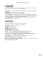
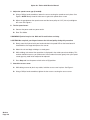
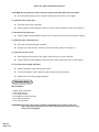
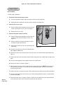
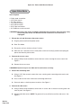
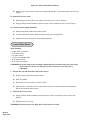
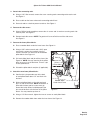
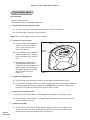
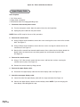
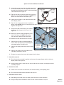
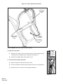
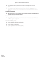
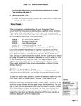
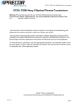
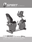
Cybex Arc Trainer 610A Service Manual
4 - Service
Warnings/Cautions
All warnings and cautions listed in this chapter are as follows:
! WARNING:
All maintenance activities shall be performed by qualified personnel.
Failure to do so could result in serious injury.
! WARNING:
Disconnect the power cord before beginning this procedure. Keep wet items
away from inside parts of the unit. Electrical shock could occur even if the unit is
unplugged.
! WARNING:
Flywheel may be hot. Wait until it cools before servicing.
! CAUTION:
Do not pinch your fingers between the belt and pulley during this procedure.
! WARNING:
Failure to release the drive belt tension may cause personal injury and may
damage the unit.
! WARNING:
Do not touch components on the lower board. A charge can remain after
unplugging the power cord and turning off the unit.
! CAUTION:
Pulley on eddy current brake is sharp. Wear work gloves to protect your hands.
Service
Page 4-1
Cybex Arc Trainer 610A Service Manual
! WARNING: All maintenance activities shall be performed by qualified personnel.
Failure to do so could result in serious injury.
For any service related concerns, call Cybex
Customer Service at 800-766-3211 (for Cybex
customers living within the USA). For customers
living outside the USA, call 508-533-4300 or fax
508-533-5183.
NOTE: Read and understand each procedure
thoroughly before servicing. Unless otherwise noted
“right” and “left” denote user orientation for all
procedures.
Test Mode
To enter Test Mode press and hold down the
Pause/end key on the display while turning the
power switch to the on (I) position. When all keys
are released “ARC” and the software revision “x.xx” are shown on the display. To exit Test Mode press
Pause/end.
Stuck Key List
It Test Mode occurs without holding any keys, a key may be stuck closed or Error 7 may have
occurred. You may need to replace the upper and/or lower display overlay. See Figure 1. If “KEY#” is
displayed you can determine which key is stuck closed by referring to the number list below.
Upper
Overlay
manual
hill
interval
weight
loss
time
scan
enter
level
strides
minute
weight
Cybex International, Inc. Medway, MA USA (508) 533-4300 www.Cybexinternational.com
resistance
Lower
Overlay
Figure 1
1
2
3
4
5
6
7
8
Service
Page 4-2
Mets
Auxiliary
Channel Up
Scan
Watts
Cardio
Level
Enter
9
10
11
12
13
14
15
16
Incline Down
Resistance Down
Channel Down
Strength
Cal/Hr
Interval
Time
Center Down
17
18
19
20
21
22
23
24
Incline Up
Resistance Up
Volume Down
Center Up
Cal
Weight Loss
Weight
Heart
25
26
27
28
29
30
32
Pause/End
Quick Start
Volume Up
Hill Interval
Dist
Manual
Strides/Minute
Cybex Arc Trainer 610A Service Manual
LED Functions
LEDs are used to indicate the status of many of the unit inputs. After entering Test Mode refer to the
following list to check that these LEDs are functioning properly:
Heart LED - Blinks on blue with every signal from the contact heart rate receiver and red for wireless
signals (Polar).
Weight LED - Blinks on when CSAFE data is being received.
Level LED - Blinks on when CSAFE data is being transmitted.
Lower Left Window - The numbers indicate actual elevation. The decimal point before the numbers
shows the activation of the level 3 position switch in the elevation motor (on above level 3). If dashes
are shown in the display, the unit is either above or below the level 3 position switch, requiring it to be
manually run through the switch to begin indicating actual elevation.
Lower Right Window - The numbers indicate resistance (0-100). The right most decimal point
indicates the pulses from the speed sensor.
Key Functions
While in Test Mode press the following keys for desired information:
Hill Interval key - Lights all of the LEDs for a short period of time.
Weight Loss key - Lights only the columns.
Strength key - Lights only the rows.
Incline
- Run elevation motor up.
Incline
- Run elevation motor down.
Resistance + (plus) - Run resistance up.
Resistance - (minus) - Run resistance down.
Distance - Press once for odometer information (DST) to appear in the speed window.
Press again for hour meter information (HRS) to appear in the speed window.
Press three times for number of starts information (USES) to appear in the speed window.
Press four times for number of positions the elevation (ELV) has ever moved. Example: if a user runs
the elevation from 2 to 3, 1 position is added to this number.
Strides Per Minute - Displays and cycles through error log. Up to 10 errors can be stored.
Scan - Clears error log when pressed twice while in error log mode.
Mets - Displays the torque in ft-lbs, (relative to LOAD).
Calories - Displays brake pulse width (PWM) value (the value of brake load in A/D counts). The number
range is relative to brake current and goes from 0-200.
Enter - Required to save setup values.
Service
Page 4-3
Cybex Arc Trainer 610A Service Manual
Error Codes
Error codes notify you of a problem condition and are displayed on the center of the console. These
codes can also help to indicate the part of the unit most likely to be causing the problem. Errors that
present a hazard to the user provide a measure of safety by causing a one second beep, stopping the
unit and locking out operation of the unit.
A log of errors can be viewed and cleared. Up to 10 errors can be stored.
To enter Test Mode: Press and hold down any key on the display while turning the power switch to
the on (I) position.
To view the Error Log: Press the Strides Per Minute key to display and cycle through error log; Press
again to cycle to the next stored error.
To clear the Error Log: Press the Scan key twice.
To exit Test Mode: Press the Stop key.
NOTE: A processor upset can cause a bAd#. See F then G.
Error
bAd0
bAd2
bAd3
Err3
Err5
Err7
ErrE
Description
Bad check sum. See F then E.
Internal RAM error. See F then E.
Watchdog timeout. See F then E.
Speed sense lost. See A and B.
No index switch sense within timed limits. This is declared when the timed elevation
reaches 0% without tripping the index. See D and A.
EEPROM error (memory lost, loads new defaults, enters Test Mode). See E.
Index switch always on (or switch disconnected or wired backwards). This means that timed
elevation has gone up 3 positions and the index is still sensed. See D.
Action
A
B
C
D
E
F
Service
Page 4-4
Check the lower board
Check the brake
Check the speed sensor and speed sensor disc
Check the elevation motor
Replace the display board is problem persists
Turn the power switch to the off (O) position and back on (I)
Cybex Arc Trainer 610A Service Manual
Speed Sensor Adjustment
Tools Required
• Phillips head screwdriver
! WARNING: Disconnect the power cord before beginning this procedure. Keep wet items away
from inside parts of the unit. Electrical shock could occur even if the unit is
unplugged.
Access
Cover
1. Disconnect the external power source.
A. Turn the main power switch above the power
inlet to the off (O) position.
B. Unplug the power cord from the power outlet.
2. Remove the access cover.
A. Using a Phillips head screwdriver, remove the
four screws securing the access cover. See
Figure 2.
B. Remove the access cover.
3. Visually inspect the target disk on the lower
pulley.
A. Turn the lower pulley slowly and look for dirt,
scratches or other damage on the target disk.
See Figure 3. NOTE: If the target disk or
speed sensor is dusty use a soft dry cloth to
wipe off the dust. A dirty, scratched or
damaged disk may cause Error 3 to occur.
Screws (4)
Figure 2
Target Disk
on Lower
Pulley
4. Measure the speed sensor gap.
A. Measure the gap between the speed sensor
and the lower pulley. It should measure 3/16”
(.48 cm) and should be parallel to the lower
pulley. See Figure 3.
Gap
Speed
Sensor
Screw
Figure 3
Service
Page 4-5
Cybex Arc Trainer 610A Service Manual
5. Adjust the speed sensor gap (if needed).
A. Using a Phillips head screwdriver, loosen the screw securing the speed sensor in place. See
Figure 3. NOTE: Gently bend the side cover to get at the speed sensor screw.
B. Adjust the gap between the speed sensor and the lower pulley to 3/16” (.48 cm) and tighten
the screw. See Figure 3.
6. Test for speed errors.
A. Connect the power cord to a power outlet.
B. Enter Test Mode.
! WARNING: Flywheel may be hot. Wait until it cools before servicing.
! CAUTION: Do not pinch your fingers between the belt and pulley during this procedure.
C. Slowly move the flywheel with your hand and check the speed LED on the lower board. It
should blink as the target disk passes the sensor.
D. Mount the unit and begin striding at a steady pace.
E. While striding, take note of the speed that is displayed in the strides-per-minute display. This
number should increase as you stride faster. If the number fluctuates greatly then your speed
sensor gap may need to be readjusted or replaced.
F.
Press Stop and turn the power switch to the off (O) position.
7. Attach the access cover.
A. While being sure not to pinch any cables, hold the access cover in place. See Figure 2.
B. Using a Phillips head screwdriver, tighten the four screws securing the access cover.
Service
Page 4-6
Cybex Arc Trainer 610A Service Manual
Drive Belts
NOTE: This procedure will cover the primary and secondary drive belts.
Tools Required
•
•
•
•
•
•
•
•
Phillips head screwdriver
3/16” Allen wrench
2 Cloths
3/8” Nutdriver or socket wrench
7/16” Socket wrench
1/2” Socket wrench (only if belt tension needs to be reset)
1/2” Open end wrench (only if belt tension needs to be reset)
3/8” Square-hole torque wrench (only if belt tension needs to be reset)
! WARNING: Disconnect the power cord before beginning this procedure. Keep wet items away
from inside parts of the unit. Electrical shock could occur even if the unit is
unplugged.
1. Elevate the unit and disconnect the power source.
A. Plug the power cord into the power outlet.
B. Enter Test Mode.
C. Elevate the unit to a minimum of level 7 incline.
D. While the unit is elevated, turn the main power switch to the off (O) position and unplug the
power cord from the power outlet.
2. Remove the access cover.
A. Using a Phillips head screwdriver, remove the four screws securing the access cover. See
Figure 2.
B. Remove the access cover.
! WARNING: Flywheel may be hot. Wait until it cools before
servicing.
3. Detach the connecting rods.
Washer
Connecting
Rod
Cap
SHCS
A. Using a 3/16” Allen wrench, remove the Cap, SHCS
and spacer securing the linkage rod. See Figure 4.
NOTE: Detach only the ends where the rods connect
to the crank.
B. Lay the linkage rod down on the frame.
NOTE: Place a cloth in between the
linkage rod and the frame to prevent
scratches.
Cloth on
the Frame
Figure 4
Service
Page 4-7
Cybex Arc Trainer 610A Service Manual
4. Remove the side covers.
Gasket
Side Cover
A. Remove the six screws and six washers
securing each side cover in place. See
Figure 5.
Screw (6)
B. Remove both side covers. NOTE: The
gasket will come off with one of the side
covers. See Figure 5.
Washer (6)
5. Remove the crank covers.
A. Using a Phillips head screwdriver, remove
the three screws securing each crank
cover in place. See Figure 6.
B. Remove both crank covers.
! WARNING: Failure to release the drive belt
tension may cause personal injury
and may damage the unit.
Figure 5
Crank Cover
6. Remove the lower pivot assembly.
Screw (3)
A. Using a 7/16” socket wrench, remove
the two screws, two lock washers and
two flat washers from the lower pivot
shaft. See Figure 7. NOTE: The tension is
now released. The primary belt can be
replaced without loosening the idler pulley.
NOTE: If you are not replacing the secondary
belt, leave the lower pivot assembly loose
in its place, skip steps 6B-8E and
continue with step 9.
Figure 6
B. Remove the lower pivot assembly out
of the secondary belt and from the frame.
See Figure 8.
Screw
7. Remove the secondary belt (if applicable).
Lock
Washer
A. Slide the secondary drive belt off the unit
and discard it.
Flat
Washer
Lower Pivot
Shaft
Figure 7
Service
Page 4-8
Cybex Arc Trainer 610A Service Manual
NOTE: If you are not replacing the primary belt skip to
step 14.
Secondary Drive Belt
(Removed in Step 7)
! WARNING: Do not touch components on the lower
board. A charge can remain after
unplugging the power cord and turning off
the unit.
Lower
Pulley
8. Remove the lower board assembly (if applicable).
A. Pull out on the lower board shield. See Figure 9.
NOTE: It will snap out.
Spacer (2)
B. Disconnect the elevation motor cable from the
lower board. See Figure 10.
Lower Pivot Assembly
C. Using a 3/8” nutdriver, remove the nut, washer
and ground wire from the stud above the
lower board. See Figure 10.
D. Using a Phillips head screwdriver,
remove the top two screws from the
lower board assembly and loosen the
bottom two screws. See Figure 11.
Figure 8
Nut
Lower Board
Shield
Washer Stud
Ground
Wire
E. Slide the lower board assembly to the
left and off the two screws, then gently
let it suspend by the cables.
9. Remove the crank shaft assembly (if
applicable).
A. Using a 9/16” socket wrench and a 9/16”
open end wrench, remove the two bolts,
four flat washers and two nuts from each
of the top pillow blocks. See Figure 12.
Elevation
Cable
Figure 9
Figure 10
Remove Top Screws
Lower Board
Assembly
Loosen Bottom
Screws
Figure 11
Service
Page 4-9
Cybex Arc Trainer 610A Service Manual
Bolt (4)
Pillow Block (2)
Pin
NOTE: Nuts (4) and
flat washers (4) are
behind the pillow
blocks.
Flat Washer (8)
Pin
Figure 12
B. Remove the crank shaft assembly
along with the primary belt, pillow blocks
and crank arms out of the unit. NOTE:
You may need to wiggle the assembly out.
There is a pin in each pillow block. Be
sure not to lose them. See Figure 13.
Crank Shaft Assembly
Primary
Drive Belt
Washer (8)
Pin (2)
Nut (4)
10. Remove the primary belt (if applicable).
A. Slide the primary drive belt off the
upper pulley and discard it. See
Figure 13.
Crank
Arm (2)
Screw (4)
11. Attach the primary belt (if applicable).
Upper
Pulley
A. Slide the new primary drive belt on
the upper pulley. See Figure 13.
B. Confirm that the primary drive belt is
straight and centered on the upper
pulley.
Pillow
Block (2)
Figure 13
12. Attach the crank shaft assembly (if applicable).
A. Confirm that a pin (removed in step 9B) protrudes about 1/4” out of the back of each pillow
block. NOTE: The pins will slide into the frame in the next step. See Figures 12 and 13.
B. Lift the assembly and slide the pins into the holes on the frame. NOTE: The pins should be
flush with the front of the pillow blocks. You may need to tap them in.
C. Using a 9/16” socket wrench and a 9/16” open end wrench, secure the two bolts, four flat
washers and two nuts (removed in step 9A) to each pillow block. See Figure 12.
Service
Page 4-10
Cybex Arc Trainer 610A Service Manual
! CAUTION: Do not pinch your fingers between the belt and pulley during this procedure.
13. Attach the lower board assembly.
A. Slide the lower board assembly over the two bottom screws and to the right.
B. Using a Phillips head screwdriver, attach the top two screws and tighten the two bottom
screws securing the lower board assembly in place.
C. Place the washer on the stud then follow it with the ground wire terminal. Use a 3/8”
nutdriver to secure the nut over the terminal. See Figure 10.
D. Connect the elevation motor cable into the lower board.
E. Place the shield into position and push in (the shield will snap in). See Figure 9.
14. Position the secondary drive belt.
A. Slide the new secondary drive belt into place on the frame.
15. Secure the lower pivot assembly.
A. Slide the lower pivot assembly through both drive belts and into place on the frame.
B. Confirm that the secondary drive belt is straight and centered on the lower pulley. See
Figure 12.
C. Confirm that the two spacers are still in place under the lower pivot shaft.
D. Using a 7/16” socket wrench, tighten the two screws, two lock washers and two flat washers
securing the lower pivot assembly in place.
16. Check the tension of the primary drive belt.
A. Press on the primary belt with your hand. You should not feel any “give” in the primary belt. If
the belt “gives”, follow step 17 through 18. Otherwise, skip to step 19. NOTE: The secondary
belt is self-tensioning.
17. Release the tension of the primary drive belt.
A. Using a 1/2” socket wrench, loosen the bottom screw on the idler pulley. See Figure 14.
B. Using a 1/2” socket wrench, loosen the top screw on the idler pulley See Figure 14.
Service
Page 4-11
Cybex Arc Trainer 610A Service Manual
NOTE: Do not adjust
the idler pulley unless This Side of
it is obvious that your Bracket
belt is not tensioned
properly.
This Side of
Bracket
Idler
Pulley
Top Screw
Bottom Screw
Figure 14
18. Torque the primary belt (if applicable).
A. Using a 3/8” square-hole torque wrench, pull up until the idler wheel rocks against the brake
and is torqued to 75 ft-lbs. NOTE: Continue holding the torque wrench at 75 ft-lbs during the
next step.
B. While holding the torque wrench at 75 ft-lbs, use a 1/2” socket wrench to tighten the top screw
on the idler pulley. See Figure 14.
C. Using a 1/2” socket wrench, tighten the bottom screw on the idler pulley. See Figure 14.
19. Attach the crank covers.
A. Place each crank cover in position.
B. Using a Phillips head screwdriver, attach the three screws securing each crank cover in place.
See Figure 6.
20. Attach the side covers.
A. Place each side cover in position in the rubber gasket.
B. Using a Phillips head screwdriver, tighten the six screws and six washers securing each side
cover. See Figure 5.
21. Secure the connecting rods.
A. Using a 3/16” Allen wrench, attach the screw securing each connecting rod to each crank.
See Figure 4.
22. Attach the access cover.
A. While being sure not to pinch any cables, hold the access cover in place. See Figure 2.
Service
Page 4-12
Cybex Arc Trainer 610A Service Manual
B. Using a Phillips head screwdriver, tighten the four screws securing the access cover.
See Figure 2.
Eddy Current Brake
Tools Required
•
•
•
•
Phillips head screwdriver
3/16” Allen wrench
7/16” Socket wrench
Work Gloves
! WARNING: Disconnect the power cord before beginning this procedure. Keep wet items away
from inside parts of the unit. Electrical shock could occur even if the unit is
unplugged.
1. Elevate the unit and disconnect the power source.
A. Plug the power cord into the power outlet.
B. Enter Test Mode.
C. Elevate the unit to a minimum of level 7 incline.
D. While the unit is elevated, turn the main power switch to the off (O) position and unplug the
power cord from the power outlet.
2. Remove the access cover.
A. Using a Phillips head screwdriver, remove the four screws securing the access cover. See
Figure 2.
B. Remove the access cover.
! WARNING: Flywheel may be hot. Wait until it cools before servicing.
3. Detach the connecting rods.
A. Using a 3/16” Allen wrench, remove the screw securing each connecting rod to each crank.
See Figure 4.
B. Place a cloth on the frame where the connecting rod will rest.
C. Rest the rod on the cloth to prevent scratches. See Figure 4.
4. Loosen the left side cover
A. Using a Phillips head screwdriver, remove the six screws and six washers securing each side
cover in place. See Figure 5.
B. Remove both side covers. NOTE: The gasket will come off with one of the side covers.
See Figure 5.
Service
Page 4-13
Cybex Arc Trainer 610A Service Manual
5. Remove the left crank cover.
A. Using a Phillips head screwdriver, remove the
three screws securing the left crank cover in
place. See Figure 6.
Loosen Screws
B. Remove the left crank cover.
! WARNING: Failure to release the drive belt tension
may cause personal injury and may
damage the unit.
Lower Pivot
Shaft
6. Release the drive belt tension.
Figure 15
A. Using a 7/16” socket wrench, loosen the two
screws on the lower pivot shaft until the screws
are raised 1/2” (1.25 cm) above the screws on the lower pivot shaft. See Figure 15. NOTE: The
drive belt tension is now released.
! WARNING: Do not touch components on the lower board. A charge can remain after
unplugging the power cord and turning off the unit.
7. Disconnect the brake cables.
A. Pull out on the lower board shield. See Figure 9. NOTE: It will snap out.
B. Locate the two brake cables on the lower board that are labeled J1 and J2.
C. Disconnect the two brake cables from the lower board.
! CAUTION: Pulley on eddy current brake is sharp. Wear work gloves to protect your hands.
8. Remove the eddy current brake.
A. Wear work gloves whenever handling the eddy current brake. The pulley is sharp.
See Figure 16.
Orientation of
the Cable
Screw (4)
Non-Threaded Hole (4)
Pulley
Pins on
Brake
Mount
Bracket
Flywheel
Secondary Drive
Belt
Figure 16
Service
Page 4-14
Threaded Hole (4)
Screw (4)
Cybex Arc Trainer 610A Service Manual
B. When the flywheel is cool, remove the secondary belt from the eddy current brake.
C. Using a 3/16” Allen wrench, first remove the two bottom screws securing the eddy current
brake in place. See Figure 16.
D. Support the brake with your hand while removing the two top screws so that it does not fall.
E. Remove the eddy current brake from the unit. NOTE: Cybex may want the old parts for
evaluation. Call Cybex Customer Service to get an RMA number.
9. Attach the new eddy current brake.
A. Locate the holes on the eddy current brake. Notice that there are four threaded holes and four
non-threaded holes. See Figure 16.
B. Locate the two pins on the brake mount bracket. See Figure 16.
C. Orient the brake with the cable away from the unit. See Figure 16.
D. Slide the brake pulley into the secondary drive belt.
E. Place the two pins in any of the non-threaded holes on the bracket. NOTE: Do not place the
pins in threaded holes.
F.
Confirm that the brake is flat against the bracket and that the drive belt is straight on the pulley.
NOTE: Continue to support the brake during the next step.
G. Using a 3/16” Allen wrench, first tighten the two top screws securing the eddy current brake.
See Figure 16.
H. Tighten the two bottom screws securing the eddy current brake.
10. Connect the brake cables.
A. Locate the J1 and J2 fast-ons on the lower board.
B. Connect the brake cables to the lower board at J1 and J2. NOTE: It does not matter which
brake cable connects to J1 and J2.
C. Place the lower board shield in position and snap it in.
11. Tension the drive belt.
A. Confirm that the secondary drive belt is straight and centered on the lower pulley. See
Figure 12.
B. Confirm that the two spacers are still in place under the lower pivot shaft.
C. Using a 7/16” socket wrench, tighten the two screws on the lower pivot shaft.
Service
Page 4-15
Cybex Arc Trainer 610A Service Manual
! CAUTION: Do not pinch your fingers between the belt and pulley during this procedure.
D. Use your hand to slowly turn the flywheel and ensure that the belt is on straight.
12. Attach the left crank cover.
A. Place the crank cover in position.
B. Using a Phillips head screwdriver, attach the three screws removed in step 5A. See Figure 6.
13. Secure the left side cover.
A. Using a Phillips head screwdriver, attach the six screws and six washers removed in step 4A.
14. Attach the left connecting rod.
A. Place the left connecting rod in position.
B. Using a 3/16” Allen wrench, attach the screw removed in step 3A. See Figure 4.
15. Attach the access cover.
A. While being sure not to pinch any cables, place the access cover in position.
B. Using a Phillips head screwdriver, attach the four screws removed in step 2A. See Figure 2.
16. Test the unit for proper operation.
A. Connect the power cord into the power outlet.
B. Turn the main power switch above the power inlet to the on (I) position.
C. Operate the unit to verify proper operation.
Elevation Motor
Tools Required
•
•
•
•
•
•
Phillips head screwdriver
3/16” Allen wrench
7/16” Socket wrench
3/8” Nutdriver or socket wrench
9/16” Open end wrench
9/16” Socket wrench
! WARNING: Disconnect the power cord before beginning this procedure. Keep wet
items away from inside parts of the unit. Electrical shock could occur even
if the unit is unplugged.
Service
Page 4-16
Cybex Arc Trainer 610A Service Manual
1. Elevate the unit and disconnect the power source.
A. Plug the power cord into the power outlet.
B. Enter Test Mode.
C. Elevate the unit to a minimum of level 7 incline.
D. While the unit is elevated, turn the main power switch to the off (O) position and unplug the
power cord from the power outlet.
2. Remove the access cover.
A. Using a Phillips head screwdriver, remove the four screws securing the access cover.
See Figure 2.
B. Remove the access cover.
! WARNING: Flywheel may be hot. Wait until it cools before servicing.
3. Detach the connecting rods.
A. Using a 3/16” Allen wrench, remove the screw securing each connecting rod to each crank.
See Figure 4. NOTE: Detach only the ends where the rods connect to the crank.
B. Place a cloth on the frame where each connecting rod will rest.
C. Rest each rod on a cloth to prevent scratches. See Figure 4.
4. Remove the side covers.
A. Using a Phillips head screwdriver, remove the six screws and six washers securing each side
cover in place. See Figure 5.
B. Remove both side covers. NOTE: The gasket will come off with one of the side covers.
See Figure 5.
5. Remove the center cover.
A. Using a Phillips head screwdriver, remove the two screws securing the center cover in place.
B. Remove the center cover.
! WARNING: Do not touch components on the lower board. A charge can remain after
unplugging the power cord and turning off the unit.
6. Disconnect the elevation cable.
A. Pull out on the lower board shield. NOTE: It will snap out.
B. Disconnect the elevation cable from the lower board and slide it out of its slot on the frame.
Service
Page 4-17
Cybex Arc Trainer 610A Service Manual
7. Remove the elevation motor.
A. Place your body next to the front
end assembly to prevent it from
pivoting and falling to the floor
during the next step.
B. Using a 9/16” open end wrench
and a 9/16” socket wrench,
remove the top bolt and nut
securing the elevation motor in
place. See Figure 17. NOTE: Do
not lose the spacer between the
bolt and nut.
Spacer
Nut
Top
Bolt
11.37”
(28.9 cm)
C. Pivot the front end assembly back
and lean it against the frame
(not the floor).
D. Using a 9/16” open end wrench
and a 9/16” socket wrench,
remove the bottom bolt and nut
securing the elevation motor in
place. NOTE: Do not lose the
spacer between the bolt and nut.
Tube
Bottom
Bolt
Spacer
Nut
E. Remove the elevation motor.
Figure 17
NOTE: Cybex may want the old
parts for evaluation. Call Cybex
Customer Service to get an RMA number.
8. Calibrate the elevation motor.
A. Connect the elevation motor to the lower board and temporarily connect the power. NOTE: The
switch should automatically adjust to the level 3 position (starting level) before adjusting the
tube nut.
B. Turn the tube with your fingers until it measures 11.37” (28.9 cm) from the center of the top
hole to the center of the bottom hole. See Figure 17.
C. Turn the main power switch above the power inlet to the off (O) position and disconnect the
power cord.
D. Disconnect the elevation motor cable from the lower board and set the motor aside until step
10A.
9. Attach the elevation motor.
A. Confirm that the two spacers (from step 7B and 7D) are in place.
B. Pivot the front end assembly back into the position it was before step 7C.
C. Place the new elevation motor in position and slide both bolts into the slots before tightening.
See Figure 17. NOTE: The top bolt goes from the left to the right, but the bottom bolt can go
either way.
Service
Page 4-18
Cybex Arc Trainer 610A Service Manual
D. Using a 9/16” open end wrench and a 9/16” socket wrench, tighten a nut on each bolt.
10. Connect the elevation cable.
A. Connect the elevation cable to the lower board and place it in the slot mentioned in step 6B.
B. Place the lower board shield in position and snap it in.
11. Secure the center cover.
A. Place the center cover in position.
B. Using a Phillips head screwdriver, attach the two screws removed in step 5A.
12. Secure the side covers.
A. Place the two side covers and the gasket in position.
B. Using a Phillips head screwdriver, attach each side cover with the six screws and six washers
removed in step 4A. NOTE: You will have to elevate the unit to level 7 to attach the bottom two
screws as discussed in step 1.
13. Attach the connecting rods.
A. Place each connecting rod in position.
B. Using a 3/16” Allen wrench, attach each connecting rod with a screw removed in step 3A. See
Figure 4.
14. Attach the access cover.
A. While being sure not to pinch any cables, place the access cover in position.
B. Using a Phillips head screwdriver, attach the four screws removed in step 2A. See Figure 2.
15. Test the unit for proper operation.
A. Connect the power cord into the power outlet.
B. Turn the main power switch above the power inlet to the on (I) position.
C. Operate the unit at all levels to verify proper operation.
Service
Page 4-19
Cybex Arc Trainer 610A Service Manual
Power Switch
Tools Required
• Phillips head screwdriver
1. Disconnect the external power source.
A. Turn the main power switch above the power inlet to the off (O) position.
B. Unplug the power cord from the power outlet and from the power inlet.
2. Remove the access cover.
Screw (2)
A. Using a Phillips head screwdriver, remove the four
screws securing the access cover. See Figure 2.
B. Remove the access cover.
3. Remove the power switch assembly.
A. Using a Phillips head screwdriver, remove the two
screws on each side of the power switch. See
Figure 18.
B. Reach inside the unit and pull the power switch
assembly up and out of the slot.
C. Make note of which fast-ons are connected to the
connectors.
Figure 18
D. Disconnect the three wires from the Filtered Power
Input Module (middle one).
E. Connect the three wires (removed from step 5D) to the new Filtered Power Input Module See
Figure 4.
F. Remove the three wires from power outlet module and remove this module from the old switch
plate.
G. Place the existing power outlet module into the new switch plate.
H. Connect the wires as shown in Figure 4.
I. With two pieces of tape, mark the top two wires to the on/off switch. NOTE: The purpose for
marking the top two wires is so that you do not accidentally bypass the on/off switch when
reconnecting the wires.
J. Remove the four wires from the on/off switch and remove the switch from the old switch plate.
K. Place the existing on/off switch into the new switch plate (positioned exactly as removed from
the old switch plate).
L. Connect the four wires as shown in Figure 4. Make sure the taped wires are connected to the
same connectors from step 5I. Remove the tape from the two wires.
Service
Page 4-20
Cybex Arc Trainer 610A Service Manual
To the
Controller
Brown
Blue
Brown
Blue
Brown
Blue
NOTE: Shown from inside the unit.
See the schematic at the end of this
chapter for more detail.
Green and
Yellow
Blue
Brown
Green and
Yellow
Slots
Figure 19
M. Verify the on/off switch is installed properly. See Figure 19.
4. Attach the power switch assembly.
A. Place the new power switch assembly into position. See Figure 18.
B. Using a Phillips head screwdriver, attach the two screws removed during step 3A into the power
switch. See Figure 18.
5. Attach the access cover.
A. While being sure not to pinch any cables, place the access cover in position.
B. Using a Phillips head screwdriver, attach the four screws removed in step 3A.
6. Test the unit for proper operation.
A. Connect the power cord into the power inlet and the power outlet.
B. Turn the main power switch to the on (I) position.
C. Operate the unit at all levels to verify proper operation.
D. Turn main power switch off to verify it is wired properly.
Service
Page 4-21
Cybex Arc Trainer 610A Service Manual
Upper Pillow Blocks
Tools Required
•
•
•
•
•
•
•
Phillips head screwdriver
3/16” Allen wrench
1/8” Allen wrench
7/16” Socket wrench
9/16” Socket wrench
9/16” Open end wrench
3/8” Nutdriver or socket wrench
! WARNING: Disconnect the power cord before beginning this procedure. Keep wet items away
from inside parts of the unit. Electrical shock could occur even if the unit is
unplugged.
1. Elevate the unit and disconnect the power source.
A. Plug the power cord into the power outlet.
B. Enter Test Mode.
C. Elevate the unit to a minimum of level 7 incline.
D. While the unit is elevated, turn the main power switch to the off (O) position and unplug the
power cord from the power outlet.
2. Remove the access cover.
A. Using a Phillips head screwdriver, remove the four screws securing the access cover. See
Figure 2.
B. Remove the access cover.
! WARNING: Flywheel may be hot. Wait until it cools before servicing.
3. Detach the connecting rods.
A. Using a 3/16” Allen wrench, remove the screw securing each connecting rod to each crank.
See Figure 4.
B. Place a cloth on the frame where each connecting rod will rest.
C. Rest each rod on a cloth to prevent scratches. See Figure 4.
4. Remove the side covers.
A. Using a Phillips head screwdriver, remove the six screws and six washers securing each side
cover in place. See Figure 5.
B. Remove both side covers. NOTE: The gasket will come off with one of the side covers. See
Figure 5.
Service
Page 4-22
Cybex Arc Trainer 610A Service Manual
5. Remove the crank covers.
A. Using a Phillips head screwdriver, remove the three screws securing each crank cover in place.
See Figure 6.
B. Remove both crank covers.
! WARNING: Failure to release the drive belt tension may cause personal injury and may
damage the unit.
6. Release the drive belt tension.
A. Using a 7/16” socket wrench, loosen the two screws on the lower pivot shaft until the screws
are raised 1/2” above the shaft. See Figure 15. NOTE: The drive belt tension is now released.
7. Remove the crank arm disk supports.
A. Using a Phillips head screwdriver, remove the one
screw securing each crank arm disk support in place.
See Figure 20.
Crank Arm Disk
Support (2)
! WARNING: Do not touch components on the lower
board. A charge can remain after unplugging
the power cord and turning off the unit.
8. Remove the lower board assembly.
A. Pull out on the lower board shield. NOTE: It will
snap out.
Screw
B. Disconnect the elevation cable from the lower board.
C. Using a 3/8” nutdriver, remove the nut, washer and
ground wire from the stud above the lower board.
Figure 20
D. Using a Phillips head screwdriver, remove the top two screws from the lower board assembly
and loosen the bottom two screws.
E. Slide the lower board assembly left and off the two bottom screws then gently suspend it by
the cables.
9. Remove the crank arms.
A. Using a 7/16” socket wrench, loosen but do not remove the one screw on each crank arm.
See Figure 21.
B. Remove the crank arms.
Service
Page 4-23
Cybex Arc Trainer 610A Service Manual
Pin (2)
Nut (4)
Pillow Block (2)
Shaft
Set Screws
(2 Each Side)
Crank Arm
Screw (2)
Flat Washer (8)
Bolt (4)
Figure 21
10. Remove the crank shaft assembly.
A. Using a 9/16” socket wrench and a 9/16” open end wrench, remove the two bolts, four flat
washers and two nuts form each of the top pillow blocks. See Figure 12.
B. Remove the crank shaft assembly along with the primary belt and pillow blocks out of the unit.
NOTE: There is a pin in each pillow block. See Figure 13.
11. Remove the top pillow blocks.
A. Using a 1/8” Allen wrench, loosen but do not remove the two set screws on each pillow block.
See Figure 21.
B. Pull each pillow block off the shaft. See Figure 21.
C. Discard the pillow blocks and pins (if applicable).
12. Attach the new top pillow blocks.
A. Slide a pillow block on each end of the shaft. See Figure 21. NOTE: Orientation of pillow block
sleeve and set screws must go toward the inside. Do not tighten the set screws until step 13F.
13. Attach the crank shaft assembly.
A. Confirm that a pin protrudes about 1/4” out of the back of each pillow block and flush with the
front. NOTE: The pins will slide into the frame in the next step.
B. Place the assembly into the primary belt and slide the pins into the holes on the frame. NOTE:
The pins should still be flush with the front of the pillow blocks. You may need to tap them in.
C. Confirm that the belt is straight on the upper pulley.
D. Using a 9/16” socket wrench and a 9/16” open end wrench, secure the two bolts, four flat
washers and two nuts (removed in step 10A) to each pillow block. See Figure 12.
Service
Page 4-24
Cybex Arc Trainer 610A Service Manual
E. Using a 1/8” Allen wrench, tighten the two set screws on each pillow block.
! CAUTION: Do not pinch your fingers between the belt and pulley during this procedure.
14. Secure the crank arms.
A. Slide each crank arm in place. NOTE: The face of each crank arm should be flush with the end
of each shaft.
B. Using a 7/16” socket wrench, tighten the one screw on each crank arm.
15. Attach the lower board assembly.
A. Place the lower board assembly over the two bottom screws and slide it to the right.
B. Using a Phillips head screwdriver, attach the top two screws removed in step 8D and tighten
the bottom two screws.
C. Connect the elevation cable to the lower board and slide it into its slot on the frame.
D. Place the washer (first) and the ground terminal (next) onto the stud and tighten with the nut
removed during step 8C.
E. Place the lower board shield in position and snap it in.
16. Attach the crank arm disk supports.
A. Using a Phillips head screwdriver, attach each crank arm disk support with one screw removed
during step 7A. See Figure 20.
17. Tension the drive belt.
A. Using a 7/16” socket wrench, tighten the two screws on the lower pivot shaft. See Figure 15.
18. Attach the crank covers.
A. Place each crank cover in position.
B. Using a Phillips head screwdriver, attach each crank cover with three screws removed in step
5A. See Figure 6.
19. Secure the side covers.
A. Place the two side covers and gaskets in position.
B. Using a Phillips head screwdriver, attach each side cover with the six screws and six washers
removed in step 4A.
20. Attach the connecting rods.
A. Place each connecting rod in position.
Service
Page 4-25
Cybex Arc Trainer 610A Service Manual
B. Using a 3/16” Allen wrench, attach each connecting rod with a screw removed in step 3A. See
Figure 4.
21. Attach the access cover.
A. While being sure not to pinch any cables, place the access cover in position.
B. Using a Phillips head screwdriver, attach the four screws removed in step 2A. See Figure 2.
22. Test the unit for proper operation.
A. Connect the power cord into the power outlet.
B. Turn the main power switch above the power inlet to the on (I) position.
C. Operate the unit at all levels to verify proper operation.
Lower Pillow Blocks
Tools Required
•
•
•
•
•
•
Phillips head screwdriver
3/16” Allen wrench
1/8” Allen wrench
2.5” (6.3 cm) Wooden block
9/16” Socket wrench
9/16” Open end wrench
! WARNING: Disconnect the power cord before beginning this procedure. Keep wet items away
from inside parts of the unit. Electrical shock could occur even if the unit is
unplugged.
1. Elevate the unit and disconnect the power source.
A. Plug the power cord into the power outlet.
B. Enter Test Mode.
C. Elevate the unit to a minimum of level 7 incline.
D. While the unit is elevated, turn the main power switch to the off (O) position and unplug the
power cord from the power outlet.
2. Remove the access cover.
A. Using a Phillips head screwdriver, remove the four screws securing the access cover. See
Figure 2.
B. Remove the access cover.
! WARNING: Flywheel may be hot. Wait until it cools before servicing.
Service
Page 4-26
Cybex Arc Trainer 610A Service Manual
3. Detach the connecting rods.
A. Using a 3/16” Allen wrench, remove the screw securing each connecting rod to each crank.
See Figure 4.
B. Place a cloth on the frame where each connecting rod will rest.
C. Rest each rod on a cloth to prevent scratches. See Figure 4.
4. Remove the side covers.
A. Using a Phillips head screwdriver, remove the six screws and six washers securing each side
cover in place. See Figure 5.
B. Remove both side covers. NOTE: The gasket will come off with one of the side covers.
See Figure 5.
5. Remove the lower pillow blocks.
A. Place a wooden block under the inner frame. See Figure 22.
B. Using a 9/16” socket wrench and a 9/16” open
end wrench, remove the two bolts, four flat
washers and two nuts from each of the bottom
pillow blocks. See Figure 22.
Pin (2)
Flat Washer (8)
Bolt (4)
C. Pull each pillow block and pin off the frame. See
Figure 22. NOTE: You may need to tilt the pillow
block up or pry it up off the frame. There is a pin
in each pillow block.
Loosen Set
Screws
(2 Each Side)
D. Discard the pillow blocks and pins (if applicable).
Pillow Block (2)
6. Attach the new lower pillow blocks.
A. Confirm that a pin protrudes out of the back
of each pillow block about 1/4” and flush with
the front.
B. Slide each pillow block on the shaft and each
pin in its slot on the frame. NOTE: Orientation of
pillow block sleeve and set screws must go
toward the inside. When installed properly the
pins should be flush with the front of the pillow
blocks. You may need to tap them in.
Wooden Block
Under Inner Frame
Nut (4)
Figure 22
C. Using a 1/8” Allen wrench, tighten the two set screws on each pillow block.
D. Remove the wooden block from under the inner frame. See Figure 22.
Service
Page 4-27
Cybex Arc Trainer 610A Service Manual
7. Secure the side covers.
A. Place the two side covers and gasket in position.
B. Using a Phillips head screwdriver, attach each side cover with the six screws and six washers
removed in step 4A.
8. Attach the connecting rods.
A. Place each connecting rod in position.
B. Using a 3/16” Allen wrench, attach each connecting rod with a screw removed in step 3A. See
Figure 4.
9. Attach the access cover.
A. While being sure not to pinch any cables, place the access cover in position.
B. Using a Phillips head screwdriver, attach the four screws removed in step 2A.
Arm and Handle Link
NOTE: The arms and handle links are removed in the same way. This procedure can be used for
both.
Tools Required
• Phillips head screwdriver
• 3/16” Allen wrench
• 7/32” Allen wrench
1. Disconnect the external power source.
A. Turn the main power switch above the power inlet to the off (O) position.
B. Unplug the power cord from the power outlet.
2. Disconnect the contact heart rate cable.
A. Unplug the contact heart rate cable from the main frame. See Figure 23.
3. Remove the handle link.
A. Using a Phillips head screwdriver or 3/16” Allen wrench, remove each screw securing the
(appropriate) cap. See Figure 24.
B. Remove the caps.
C. Slide the handle link off the foot plate arm shaft.
D. Slide the handle link off the arm shaft. NOTE: Arm will move freely. Hold in place until step 4.
Service
Page 4-28
Cybex Arc Trainer 610A Service Manual
Heart Rate
Cable Plug
Contact Heart
Rate Cable
Figure 23
4. Remove arm.
A. Using a 7/32” Allen wrench remove the two screws and two washers securing the arm to the
frame.
B. Remove arm from frame.
5. Attach the new arm.
A. Slide the (appropriate) arm into the frame.
B. Using a 7/32” Allen wrench secure the arm to the frame using the screws and washers
removed in step 4A.
C. Using a Phillips head screwdriver or 3/16” Allen wrench, attach handle link with the
(appropriate) screw securing the cap. See Figure 24.
Washer
Foot Plate Arm Rear
Cap
SHCS
Foot Plate Arm Front
Linkage Rod
SHCS
Cap
Washer
Handle Link
Figure 24
Service
Page 4-29
Cybex Arc Trainer 610A Service Manual
6. Attach the new handle link.
A. Slide the handle link onto the arm shaft and foot plate arm shaft.
B. Using a Phillips head screwdriver or 3/16” Allen wrench, secure handle link with the screws and
(appropriate) cap removed in step 3A.
7. Connect the contact heart rate cable.
A. Plug the contact heart rate cable into the plug in the main frame. See Figure 23.
Pedal Arm and Foot Plates
NOTE: The pedal arms and foot plates are removed in the same way. This procedure can be used for
both.
Tools Required
• Phillips head screwdriver
• 3/16” Allen wrench
• Threadlocker
1. Disconnect the external power source.
A. Turn the main power switch above the power inlet to the off (O) position.
B. Unplug the power cord from the power outlet.
2. Remove the foot plate and pedal arm.
A. Using a Phillips head screwdriver or 3/16” Allen wrench, remove each SHCS securing the
(appropriate) cap. See Figure 25.
B. Remove the cap.
C. Slide the foot plate off the foot plate shafts (if applicable).
D. Slide the (appropriate) arm off the shaft (or shafts).
3. Attach the new foot plate and pedal arm.
A. Slide the (appropriate) arm on the shaft (or shafts).
B. Slide the foot plate on the foot plate shafts (if applicable).
C. Place a drop of threadlocker on one of the SHCS. Place another drop of threadlocker in the
shaft (where the SHCS will be tightened into).
D. Using a Phillips head screwdriver or 3/16” Allen wrench, attach cap with the (appropriate)
SHCS securing the cap. See Figure 25. NOTE: SHCS must be tightened to a minimum of
100 inch-pounds.
Service
Page 4-30
Cybex Arc Trainer 610A Service Manual
Rear Pedal
Arm
Front Pedal
Arm
Foot Plate
Small Cap (2)
Foot
Plate
Shafts
SHCS (2)
Threadlocker
Figure 25
Lower Control Board
Tools Required
• Phillips head screwdriver
• 3/8” Nutdriver or socket wrench
• ESD (Electro Static Discharge) grounding strap
! WARNING: Disconnect the power cord before beginning this procedure. Keep wet items away
from inside parts of the unit. Electrical shock could occur even if the unit is
unplugged.
1. Disconnect the external power source.
A. Turn the main power switch above the power inlet to the off (O) position.
B. Unplug the power cord from the power outlet.
2. Remove the access cover.
A. Using a Phillips head screwdriver, remove the four screws securing the access cover.
See Figure 2.
B. Remove the access cover.
Service
Page 4-31
Cybex Arc Trainer 610A Service Manual
! WARNING: Flywheel may be hot. Wait until it cools before servicing.
3. Disconnect the cables from the lower board.
A. Pull out on the lower board shield. NOTE: It will snap out.
B. Disconnect the cables from the lower board. This includes the elevation motor cable, display
cable (P1), AC line 1 (J3 black), AC line 2 (J7 white), eddy current brake cable (J1 and J2) and
speed sensor cable (J4).
C. Using a 3/8” nutdriver, remove the nut, washer and ground wire from the stud above the lower
board. See Figure 10.
! WARNING: Do not touch components on the lower board. A charge can remain after
unplugging the power cord and turning off the unit.
4. Remove the lower board assembly.
A. Using a Phillips head screwdriver, remove the top two screws from the lower board
assembly and loosen the bottom two screws.
B. Slide the lower board assembly left and off the bottom screws. NOTE: Cybex may want the old
parts for evaluation. Call Cybex Customer Service to get an RMA number.
5. Attach the lower board assembly.
A. Place the lower board assembly over the two bottom screws and slide it to the right.
B. Using a Phillips head screwdriver, attach the top two screws removed in step 4A and tighten
the bottom two screws.
6. Connect the cables to the lower board.
A. Connect the cables to the lower board. This includes the elevation motor cable, display cable
(P1), AC line 1 (J3 black), AC line 2 (J7 white), eddy current brake cable (J1 and J2) and speed
sensor cable (J4).
B. Place the washer (first) and the ground terminal (next) onto the stud and tighten with the nut
removed during step 3C.
C. Place the lower board shield in position and snap it in.
7. Test the unit for proper operation.
A. Connect the power cord into the power outlet.
B. Turn the main power switch above the power inlet to the on (I) position.
C. Operate the unit at all levels to verify proper operation.
Service
Page 4-32
Cybex Arc Trainer 610A Service Manual
Lower Control Board Fuses
TOOLS REQUIRED
• Phillips screwdriver
• Needle nosed pliers
• Two (2) Fuses, part number EF-12417.
1. Disconnect the external power source.
A. Turn the main power switch above the power inlet to the off (0) position.
B. Unplug the power cord from the power outlet.
! WARNING: Disconnect the power cord before continuing this procedure. Keep wet items away
from inside parts of the unit. Electrical shock could occur even if the unit is
unplugged.
2. Remove the access cover.
A. Using a Phillips screwdriver, remove the four screws and four washers securing the access
cover. See Figure 2.
B. Remove the access cover.
! WARNING: Flywheel may be hot. Wait until it cools before servicing.
! WARNING: Do not touch components on the lower board. A charge can remain after
unplugging the power cord and turning off the unit.
3. Replace the fuses.
A. Locate the lower board.
B. Pull out on the lower board shield (it will snap
out). See Figure 26.
Fuses
Finned
Fasteners
(4)
C. Locate the fuses in the upper left hand corner
of the control board. See Figure 26.
D. Replace the old fuses with the new fuses.
E. Place the lower shield (removed in step 5B)
into position and secure the finned fasteners
(the shield with snap in).
F. Attach the access cover removed in steps 2A
and 2B. NOTE: Be careful not to pinch any
cables.
Lower Board Shield
Figure 26
Service
Page 4-33
Cybex Arc Trainer 610A Service Manual
Upper Display Board
Tools Required
• Phillips head screwdriver
• ESD (Electro Static Discharge) grounding strap
1. Disconnect the external power source.
A. Turn the main power switch above the power inlet to the off (O) position.
B. Unplug the power cord from the power outlet.
NOTE: Wear an ESD strap for the rest of this procedure.
2. Remove the console front.
A. Using a Phillips head screwdriver,
remove the screw securing the
access cover to the console
back. See Figure 27.
B. Using a Phillips head screwdriver,
remove the four screws securing
the console front to the console
back.
C. Gently pull the console front
forward and disconnect these
cables from the display board: the
display cables; the contact heart
rate cables; ground wire and the
polar heartrate cable. See
Figure 28.
Screw (1)
Access
Cover
Screws (4)
Figure 27
3. Remove the display board.
A. Using a Philips head screwdriver, remove the five display board mounting screws.
B. Lift and rotate the display board to the right and unplug the three overlay ribbon cables from
the display board. Set the display board aside. NOTE: Cybex may want the old parts for
evaluation. Call Cybex Customer Service to get an RMA number.
4. Attach the new display board.
A. Plug the overlay ribbon cables into the appropriate connectors in the display board.
B. Using a Phillips head screwdriver, securing the display board to the console with the five
screws removed in step 3A.
5. Connect the cables.
A. Connect these cables into the display board: the display cable; the two upper switch
overlay connectors; the lower switch overlay connector; the contact heart rate cable;
ground wire and the polar heartrate cable. See Figure 28.
Service
Page 4-34
Cybex Arc Trainer 610A Service Manual
Upper Display Board
Upper Switch
Membrane Connectors
(on front side)
Mounting Screws (5)
RJ-45 Port
Polar
connector
CSAFE
Connector
Display Cable Ports
Polar Heart
Rate Board
Ground wire
Contact Heart
Rate Ports
Lower Switch
Membrane Connector
(on front side)
Figure 28
6. Check the connections:
A. Check to see that all of the cables are connected firmly in their proper place.
7. Secure the console back.
A. While being sure not to pinch any cables, use a Phillips head screwdriver to tighten four screws
securing the console front to the console back.
B. Using a Phillips head screwdriver secure the access cover to the console back with the screw
removed in step 2A.
Service
Page 4-35
Cybex Arc Trainer 610A Service Manual
Upper Display Cable
Tools Required
• 7/32” Allen wrench
• Phillips head screwdriver
• ESD (Electro Static Discharge) grounding strap
1. Disconnect the external power source.
A. Turn the main power switch above the power inlet to the off (O) position.
B. Unplug the power cord from the power outlet.
NOTE: Wear an ESD strap for the rest of this procedure.
2. Remove the console front.
A. Using a Phillips head screwdriver, remove the screw securing the access cover to the console
back. See Figure 27.
B. Using a Phillips head screwdriver, remove the four screws securing the console front to the
console back. See Figure 27.
C. Gently pull the console front forward and disconnect these cables from the display board: the
display cable; the contact heart rate cable; ground wire and the polar heartrate cable.
See Figure 28.
3. Remove the console mount.
A. Using a 7/32” Allen wrench, remove the four screws and four lock washers securing the
console mount in place. See Figure 29.
B. Remove the console mount by lifting upward.
4. Remove the upper display cable.
A. Disconnect the upper display cable from the lower display cable. See Figure 29.
5. Attach the new upper display cable.
A. Locate the end of the upper display cable with the single connector. See Figure 29.
B. Connect the upper display cable to the lower display cable. NOTE: If you are changing the
lower display cable disregard this step.
Service
Page 4-36
Cybex Arc Trainer 610A Service Manual
7. Attach the console mount.
A. Insert the upper display
cable into the console
mount and place on top of
the base assembly. See
Figure 29.
Console
Assembly
Upper
Display
Cable
B. Using a 7/32” Allen
Wrench, attach the four
screws and four lock
washers securing the
console mount in place.
Washers (4)
Lower
Display
Cable
5. Connect the cables.
Screws (4)
Contact Heart
Rate Cables
A. Connect these cables into Figure 29
the display board: the
display cable; the two
upper switch membrane connectors; the lower switch membrane connector; the contact heart
rate cable and the polar heartrate cable. See Figure 28.
6. Check the connections:
A. Check to see that all of the cables are connected firmly in their proper place.
7. Secure the console back.
A. While being sure not to pinch any cables, use a Phillips head screwdriver to tighten four screws
securing the console front to the console back removed in step 2B.
B. Using a Phillips head screwdriver secure the access cover to the console back with the screw
removed in step 2A.
Lower Display Cable
Tools Required
•
•
•
•
•
•
Flat head screwdriver
Phillips head screwdriver
9/16” Open-end wrench or socket wrench
3/16” Allen wrench
Tape
Wire Cutters
! WARNING: Disconnect the power cord before beginning this procedure. Keep wet items away
from inside parts of the unit. Electrical shock could occur even if the unit is
unplugged.
1. Disconnect the external power source.
A. Turn the main power switch above the power inlet to the off (O) position.
B. Unplug the power cord from the power outlet.
Service
Page 4-37
Cybex Arc Trainer 610A Service Manual
2. Remove the access cover.
A. Using a Phillips head screwdriver, loosen the four screws securing the access cover. See
Figure 2.
B. Remove the access cover.
3. Remove the console assembly.
A. Using an Allen wrench, remove the four screws and four lock washers securing the console
assembly in place.
B. Carefully lift console assembly and disconnect the upper display cable from the lower display
cable. See Figure 29.
4. Remove the left wheel.
A. Place a wooden block under the unit to take the weight off the left wheel.
B. Using a 9/16” wrench and a 3/16”
Allen wrench, remove the bolt and nut
securing the left wheel in place. See
Figure 30.
5. Detach the lower display cable.
! WARNING: Do not touch components on
the lower board. A charge can
remain after unplugging the
power cord and turning off the
unit.
A. Pull out on the lower board shield.
NOTE: It will snap out.
Bolt
Access
Holes
Block
Nut
Figure 30
B. Disconnect the display cable from the
lower board. See Figure 31.
C. Remove the lower display cable from
the wire holder bracket. See Figure 31.
6. Attach the new lower display cable.
Shield
A. Using wire cutters, cut both sets of the
old contact heart rate cables from
the old lower display cable (these are
the small pairs of brown and black
cables). See Figure 29.
P1 on
Lower Board
NOTE: The heart rate cables have a left and a
right side, they must be wired correctly.
Figure 31
Service
Page 4-38
Wheel
Cybex Arc Trainer 610A Service Manual
B. Locate the new contact heart rate cables connected
to the lower display cable. The right side cables are
located in the outermost locations in the lower display
cable connector. See Figure 32.
Left Side
Heart Rate
Wires
Right Side
Heart Rate
Wires
C. Tape the new pairs of contact heart rate wires to the
old wires cut in step 6A. See Figure 33. NOTE: One
brown wire and one black wire make a pair.
D. Locate the new cable’s 10 pin connector end of the
lower display cable.
E. Tape the new 10 pin connector to the old lower
display cable. NOTE: Be sure to tape the correct ends Figure 32
together. See Figure 33.
F.
Using a flat head screwdriver pry the contact
heart rate cable plug out of the frame. See
Figure 23.
G. Gently pull all three cables through the frame
tubes. See Figure 34. NOTE: Stop pulling
when the new cables exit the frame tubes.
H. Remove the tape and discard the old cable.
I.
Confirm that the cable is routed through the
access holes (see Figure 30) and through the
wire holder bracket (see Figure 35).
J. Connect the display cable to the lower control
board.
K . Connect the contact heart rate cables to the
cable plugs removed in step 6F.
Left Contact
Heart Rate
Cables
Display
Cables
Right Contact
Heart Rate
Cables
Figure 33
L. Plug the two contact heart rate cable sockets into the frame.
7. Attach the console.
A. Place the console assembly in position and connect the upper display cable to the lower
display cable. See Figure 29.
B. Using an Allen wrench, attach the four screws and four lock washers securing the console
assembly in place.
8. Secure the cable.
A. Check to see that all of the connectors are connected firmly in their proper place.
B. Place the lower board shield in position and snap it in.
9. Attach the access cover.
A. While being sure not to pinch any cables, place the access cover in position.
B. Using a Phillips head screwdriver, attach the four screws removed in step 2A.
Service
Page 4-39
Cybex Arc Trainer 610A Service Manual
Left Contact
Heart Rate
Cable
Right Contact
Heart Rate
Cable
Lower Display
Cable To Lower
Board
Figure 34 NOTE: Frame only shown for cable routing.
10. Attach the left wheel.
A. Using a 9/16” wrench and a 3/16” Allen wrench, attach the bolt and nut
securing the left transport wheel in position. See Figure 30.
Wire
Holder
Bracket
B. Remove the wooden block from under the unit.
11. Test the unit for proper operation.
A. Connect the power cord into the power outlet.
B. Turn the main power switch above the power inlet to the on (I) position.
C. Operate the unit at all levels to verify proper operation.
Figure 35
Service
Page 4-40
Cybex Arc Trainer 610A Service Manual
Display Overlays
NOTE: This procedure will cover the upper and/or lower display overlay. They are removed and
replaced the same.
Tools Required
• Phillips head screwdriver
• ESD (Electro Static Discharge) grounding strap
• Razor blade
1. Disconnect the external power source.
A. Turn the main power switch above the power inlet to the off (O) position.
B. Unplug the power cord from the power outlet.
NOTE: Wear an ESD strap for the rest of this procedure.
2. Remove the top console front.
A. Using a Phillips head screwdriver, remove the screw securing the access cover to the console
back. See Figure 27.
B. Using a Phillips head screwdriver, remove the four screws securing the console front to the
console back.
C. Gently pull the console front forward and disconnect these cables from the display board: the
display cables; the contact heart rate cables; ground wire and the polar heartrate cable. See
Figure 28.
D. Using a Philips head screwdriver, remove the five display board mounting screws.
E. Lift and rotate the display board to the right and unplug the three overlay ribbon cables from
the display board. Set the display board aside.
3. Remove the display overlays.
A. Use a razor blade to peel up a corner of the upper and lower display overlays and pull off the
overlays.
4. Attach the display overlays.
A. Remove the paper backing from the new display overlays.
B. Slide the ribbon cable through the slot.
C. Carefully place the display overlays in place within the indentation on the console front.
D. Firmly rub the display overlays so that it adheres to the console.
5. Attach the display board.
A. Plug the overlay ribbon cables into the appropriate connectors in the display board.
Service
Page 4-41
Cybex Arc Trainer 610A Service Manual
B. Place the display board in position and secure with five mounting screws removed in
step 2D.
C. Place the console front in position and connect these cables to the display board: the
display cables; the contact heart rate cables; ground wire and the polar heartrate cable. See
Figure 28.
6. Attach the console front.
A. While being sure not to pinch any cables, secure the console front to the console back with the
four Phillips head screws removed in step 2B.
7. Attach the access cover.
A. Using a Phillips head screwdriver, secure the access cover to the console back with the screw
removed in step 2A. See Figure 27.
8. Test the new display overlay.
A. Turn the main power switch to the on (I) position.
B. Plug the unit into the power outlet.
C. Try each key to be sure that it functions properly.
Service
Page 4-42