1
.
.'~
- I•
:'.:', :-,
,.
\",,':'-;-.:''''!
-:
\.,
,
'
••
. ." . . •
'
,":"
':
,"",
':
c,
.:
•
,"
'
:." • •,
:
<
. .. :"'<;/<':;,C;" SERVICE "MANUAL .
i,
r
.\
.
.'
.
.
I
I
..
i
..1
.
12" '. COLOR DISPLAY'
,
DOtlI DrYl~M .
-SUPER VISION fbJ3JillJlflnlJ{][I1J SUPER VISION
'
.
'.
,
.
.
TM
,
.
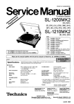
IMPORTANT SERVICE SAFETY INFORMATION Super Vision IV/IVM
Super Vision 640/630
;
Operatic.n,of monitor outside of cabinet or with back removed involves a shock hazard. Work on these models should only be performed by those who arll thoroughly familiar. with prccau
.
tions neCessary when working on high voltage equipment•. • • • ... PROTECT YOUR CUSTOMER • • • • • Llnspect all lead dress to make certain that leads are not pinched and that hardware is not lodged between the chassis and, other metal parts in the monitor. Exercise care when servicing this chassis with power applied. Many 8 plus and high voltage RF terminals are exposed which. if carelessly contactlld. can cause serious shock or result in dam
age to the chassis. Maintain interconnecting ground lead con
. ncetions bet.ween chassis. escutcheon and picture tube dag cluster
when operating chassis. The +8 Adj.Control in this monitor is
sealed in order to.protect the user from X-ray irradiation. The ... '
B Adj.Control should oot normally have to be adjusted.But iC it
is..cr Ie it is replaced due to damage.check the +B voltage to as
sure that. it is within specifications after adjustment.Then seal
this control according to the manuCacture's specification.
2.Replace all protective devices such as non·metaUic control knobs.cabinet back.l\djustment covlu·s.shields.etc. Certain H Y failures can increase X-ray radiation. Monitors should not be operated with H Y levels exceeding the specified rating for th«; chassis type. The maximwn operating H Y specified for the chassis used in these monitor is 22 KV at zero beam current with a line voltage of 120Y AC. Higher voltage may also increase possibility of failure in H·Ysupply. It is important to maintain specified values of aU components' in the horizontal and high voltage circuits and anywhere else in the monitor that could cause a rise in high voltage or operating supply voltage.No changes should be made to the original de
sign olthe monitor. Components shown in the shaded areas od the schematic diagram and/or. identified by
in the re
placement. parts list should be replaced only with exact Factory recommended replacement parts. The use of unauthorized substitute parts_ may create a shock. fire.X- ray radiation.or other hazard. To determine the presenCe of high voltage. use an accurate.high . impedance.H Ymeter connected between the second anode leitd and the CRT dag groundin~ device_When servicing the High Yoltage System.remove static charge e~om it by connp.cting a 10K ohms resistor in series with an insulated wire (such as a test probe) between picture tube dag and 2nd anode lead. (AC, line cord disconnected Crom AC supply.) &. *
3.To be sure tllat no shock hazarc!exists.a check for the pres· enee oC leakage current should be made at eech exposed metal' part having a return path to the chassis(jack.cabinet metal. screw heads. knobs.shaftli.etc.)in the following manner. Plug the AC line cord directly into a 120Y AC receptacle.(Do not use an Isolation Transformer during these checks. ) All tP.Sts must be repeated with' the AC Hne cord plug connections. l'e~ versed. (If necessary.a non-polarized AC adapter plug must be' used for .the purpose of completing these checks. Do not other
wise operate the monitor with an adapt,.r.) Ie available.measure leakage current using an accurate leakage current tester.Any reading oCO.35MA or more· is excessive and indicates II potential shock hazard which must be corrected be
Core returning the monitor to the owner. If a reliable leakage current tester is not available. this alter nate method of meesurement sho~I1d be used. Using two clip leads. connect a 1500 ohm:l.l0 watts resistor paralleled by a 0.15MFeapacitor.inseries with a known earth ground.such as.a water pipe or conduit. and the meta} part to be checked. Use a VTYM or YOM with 1000 ohms per volt.or higher.sensitivity to measlire the AC voltage drop across the resistor. Any reading of 0.35 volt RMS or more is excessive and indicate&a poten~ tial shock hazard.This must be corrected before returning the monitor to the own.er. !
. !,
0)
a
0
_-----'ACL------,
VOLT METER The picture tube. used in this· monitor employs integral implo
sion protection. Replace with a tube at the same type number ,Cor continued safety.Do not IiCt picture tube by the neck.Han
dIe the picture tube only when wearing shatter-proof goggles and after discharging the high voltage completely.Keep l)ttiers withoutshafter-proofl goggles away. \.
I
1500 OHMS
lOW
O.ISMF
When removing springs or spring mounting parts from the
chassis.shatter-proof gottgles must be worn.Keep others without
shatter-proof goggles away.
• • • • e' SAFETY INSPECTION • • lor e' •
Before returning the monitor to the user. per Corm the following
safelY checks:
TEST PROBE
TO EXPOSED
METAL PARTS_
.TO KNOWN
EARTH GROUND.
I
I
,
.
IMPORTANT NOTICE FOR SERVICE PERSONNEL BEFORE SERVIC'ING
PLEASE READ BEFORE ATTEMPTING SERVICE
1.' While the monitor isin operation, do not attempt to connect or disconnect any wires.
10',
sis
2. Make sure the power cord is,disconnected before replacing any components in the monitor.'
rol
3. When the power is on, do not attempt to short any portion of the circuit. This shorting may
cause damage to the transistors in the monitor.
as·
lal
4. When servicing the H; V. area, be certain tl:lat the C.
R~ T anode is.safely discharged to ground
before removing the anode cap.
Ill.
5. Caution, must be exercised when servicing this monitor. )0
, The regulator has no current Iimitinganq even a momentary short of an output voltage could cause destruction of the pass transistors.
;I.S
~e-
be
!r
gt'
i
le-
tr..
ip
a
a
a
ly
,
II i
I
I
'
"'i,
Ig
~-
Ie
/
....
- 1
I Product. Outline 'I
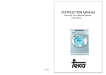
This model is a 12-inch color display monitor, used for a personal computer terminal. Its input is TIL
s~parate signals. The input terminal is an 8-pin DIN )ack.
Specifications
CAT
12-inch type with 646.8 mm R
• Facing: Non-glare' face 'plate
630/640A, B, S
, 630/640U, J
Facing: Glare face plate
• Screen phosphor: 630/640
B22 (Short persfstence)
Signal input '
Separate R, G, B, I, H, V
• R, G, B, I: ." Positive
• Sync:
Positive or negative
Power Supply
Wattage
Cabinet
Dimensions
Weight
Scanning frequency
Local commercial power supply
SOW
Plastic
322 (W) x 309 (H) x 372 (D) mm .
12 kg
24.S kHz (Horizontal)
54.3 Hz (Vertical)
OPERATION
1. 2. 3. 4. 5. Plug the display and the computer into AC outlets.
Set the color mode switch on the rear panel.
Connect the signal input terminal
the rear panel to the computer using the optional cable.
Turn on display monitor and computer.
The green power indicator (just above tbe power 'switch), lights, then the CRT ·screenbrightens.
(There may be 9haracters displayed.)
6. After the monitor warms up, set brightness and contrast if necessary.
7. Position of the image, image area, and focus are preset at the factory, so you don't have to adjust
these. Depending oriyour computer, image width, height, and position may differ from the stan
dard settings', In such a case, reset as necessary (controls are on the rear panell.·
sm
SIGNAL INPUT CONNECTORS
.
.
Signals are input through a DIN 8P connector. Each signal is assigned as following:
1 . Pin assignment
[REAR VIEW] .- 2
2.
Pin assignment
:
i
.!
Pin no.
Signal
1
Reserved for special TEXT signal 2
Red video signal 3
Green video signal 4
Blue video signal 5
Intensity signal 6
Signal ground 7
Horizontal or composite sync signals
8
Vertical sync signal ~.
..
.
.. HOW TO SET COLOR MODE
1.
Set~ing
the colarmade .;
The color mode switch (a five-switch DIP unit) is on the rear panel. Set it as follows according
to your computer.
(1) Mode 1
. Color
Color mode switch
.
... OPEN
I-
~
2
1
0
3
0
oj
4
.
~'.
..
'
.
.
,
IBM
.,.
..
5
:
~.
.. . .
(2) Mode 2
..
Color mode switch
OPEN
I~
1
~
0
2
3
Color
0 01
4
AT & T (OLIVETTI) *
5
(3) Mode 3
Color mode switch
OPEN
I~
1
.
~
0
2
3
0
Color 01
APPLE
5
4
(4l Mode 4·
Color mode switch
I1
Color
.
OPEN
~
0
D
2
3
4
01
NTSC 5
-3
• Note - ADDENDUM fgr AT&T PC6300 and compatibles
630/640 E, U. A,B. S are factory-set to use with IBM PC/XT/AT Of compatibles. You may need the following adjustment
.in order to obtain maximum performance in display when you use with AT&T PC6300. PC6300 PLUS computer and compatibles.
,. Curl at top D
Turn H. HOLD counter-clockwise.
Turn HoPOSI clockwise .
. 2. Small screen size
al Horizontal size
Turn H. SIZE c;ounter-clockwise.
bl Vertical size Turn V. SIZE counter-clockwise.
CJ 3. Characters missing at top Turn V. HOLD clockwise..
-4
2.
Setting the sync signal input mode (fifth color mode switch)
The sync signal of nearly any personal computer can be inp~t by turning off the fifth DIP switch.
But the sync signal of a few computers can be input only with this switch on. The following
table shows the switch setting for a number of sync signals.
Color mode switch
10 0
D 0
2
1
Condition
OPEN
4
3
~I
A
8
H. sync: Negative TTL level
V. sync: Positive TTL level
.
5
C
10
1
OPEN
0
0
0
2
3
4
Signal type
H. sync: Positive TTL level
V. sync: Negative TTL level
H. V. sync composite, positive
H. sync: Positive TTL level
V.sync: Positive TTL level (AT&T)
a
~I
H. sync: ~egative TTL level
V. sync: Negative,TTL level (18M,
JAPANESE)
b
5
e'
H. V. sync composite. ne'gative
c
3 '. Setting the signal color display mode
Turnin'g of the TEXT switch (on the front of the unit) changes the display to single-color mode.
Super Vision monitor can now be used as a monochrome display monitor. There are four basic
monochrome modes: green, amber, reversed white, and white on blue. The monochrome mode
is set by the third and fourth DIPswitches as follows.
,
'
I
Color mode switch
, color
OPEN, '
10
Green'
I
1
D
,2
~
~
01
3
4
5
OPEN
i
Amber
r
I
l
~ ,
-
10 0
1
••
Reversed white
\0
1
~-
3
2
01
~.,
4
5
OPEN
0
~
~
01
2
3
4
5
OPEN
*.
White on blue
10 0
1
- -Note: In reversed white or white on blue
mode, the following phenomena
may appear as described on the
right. These are quite normal for this
mode.
2
~
~
01
3
4-
5
Uppermost raster does nofappear
or its disappearing position varies 'depending on the brightness, /'
v
V
One or both ends are brighter
than other areas.
......
lowest two or three rasters run off the screen.
- 5
INDICATORS· AND CONTROLS POWER INDICATOR (GREEN LEDI
POWER SWITCH (PUSH ON. PUSH OFF)
TEXT SWITCH
BRIGHTNESS
CONTRAST
COLOR MODE SWITCH
VERTICAL SIZE
FOCUS
. HORIZONTAL SIZE
VERTICAL POSITION·
~' " ""'VERTICAL LINEARITY
• '\:
VERTICAL SYNC
.• ' . '
~ORIZONTAL
POSITION
. ' " HORIZONTAL SYNC
VIDEO SIGNAL INPUT TERMINAL AC CORO
- 6
ADJUSTING THE DISPLAY
;
1. H. SIZE
( ..
If the horizontal size of the screen image is too short or too long. adjust the H. SIZE control for
the correct size. (See illustration 1.)
2. V. SIZE
If the vertical size of the screen image is too short or too long, adjust theY. SIZE control for the
correct size. (See illustration 2.1
.'
3. H. POSt
I
.
I
I
If the screen image shifts horizontally. adjust the H.
tion 3.)
.
pas!. control for a correct image.
(See illustra
4. V. POSI.
·If the
scree~image
shifts vertically, adjust the V. POSI. control for a correct image. (See illustration 3.1
5. H. HOLD
If the screen image has horizontal stripes or if the. image moves left or right, adjust the H. HOLD control for a clear stable image. (See illustration 4.1 6, V. HOLD , If the screen image moves or overlaps vertically, adjust the V. HOLD control for astable image. (See illustration 4,1
7. FOCUS Adjust the focus· for the sharpest image. (See illustration 6.1 8. V. LIN. Adjust the y.LlN control so the height of characters is even over the whole screen. (See illustration 7.1 9. CONTRAST Turning the. CONTRAST control clockwise increases the contrast, turning it counterclockwise
. decreases the contrast.
10. BRIGHT
Turni'ng the iRIGHT control clockWise makes the screen brighter, turning it counterclockwise makes
it darker.
11. SUB-CONTRAST
To adjust the subcontrast, display a screen of characters then turn the BRIGHT control to the clic~
stop position, and the CONTRAST control fully clockwise. Now adjust the SUB-CONTRAST control
(VR 140) to the position just before the characters ·become saturated ..
12. H. CENTER
To adjust horizontal centering turn the BRIGHT and the CONTRAST controls fully clockwise with
nothing displayed on the screen. Then adjust the H. CENTER VR (R742) so that the raster is centered
on the screen.
- 7
13. SIDE-pee
Depending on computer models with which display monitors
are connected, pincushion or barre'! distortion appears on the
right and left edge portions of their screen areas as shown
in Fig. 1.. The distortion on the right and left screen portions
can be minimized by turning the "SIDE-PCC" potentiometer,
clockwise or counter-clockwise, for optimum distortion
correction results.
1\
J\
I \
I \
I ,
r I
\
I
I
"
"
:-.
.
.~
•
- 8
I
\ I
\ I
Problems
Width of the image, is
not correct.
1
4
5
The image ,has, a
diagonal stripes.
§§ The image moves ver
tically, (flops).
m
I
f
"
The image is blurred.
,
There is nQ image.
8
,
!
,
The screen is dark.
9
,
/@\
Right
I @) ~
Up
Down
,H. HOLD
I@\
V. HOLD
I @\
FOCUS
I@\
V.lIN
I@\'
'CONTRAST
.
ct
Bright
"
..;.'9
Left
V. POSITION
D
I~II
Narrow
H. POSITION
HH H HH ..... HHHHH·· ~,"
c
,
Wide
HH H H H .....
Character 'heights on,
the screen are not
uniform.
7
I@\
~~G=l1
.
6
V. S(ZE
~·lEIJ
[gTI [E5J 3
,
w~:O~a"ow [2J[C]
Position of the image is
not correct.
' ,Adjustmen~
,H. SIZE
BJ BlJ . Height oftheimage is '
not correct.
2
,
;::-s
Dark
"',' BRIGHT
Bright
P.z-A
Dark'
.
ALIGNMENT PROCEDURE
1
GENERAL ALIGNMENT
;
1.A PRELIMINARY ADJUSTMENT
. 1.A.l
Read and observe all safety precautions shown earlier iii this manual.
1.A.2 Connect AC power and make sure that it is within the specified line voltage ± 2 V.
1.A.3 Allow the monitor to warm up for at least 30 minutes.
Roughly adjust the FOCUS control. 1.AA
·1.A.5
Connect a correctly adjusted color computer. 1.B
•
Vec ADJUSTMENT 1.B.1· 1.B.2 1.B.3 1. BA 1.C
Set the BRIGHT 'control fully clockwise.
Set the SCREEN control to its center ~osition.
Setthe H.HOLDcontrol to the center of the range of pictur~ stability.
Adjust vce control VR920 to there is 115 ± 1.0 VOC between + B and chassis ground.
HORIZONTAL AND VERTICAL ADJUSTMENT
1.C.1 .
Adjust L702 and VS701G)(H. HOLDl,and VS701@(H. POSIl for the best horizontal raster
alignment.
"
.
1.C.2 . Adjust VS701 @(V. HOLD), VS701 @(V. LIN), VS701@(V. SIZEl,and VR628 (v. POSI.)
for the best vertical raster alignment.
1.D
FOCUS ADJUSTMENT
1 . D. 1 Display a full screen of characters ..
1.0.2 Adjust the FOCUS control for the sharpest detail at the center of the screen.
1.E
RGB CUTOFF WHITE BALANCE
1.E.1 1.E.2 1.E.3
1.EA
1.E.5 1.E.6 1.E.7 1.E.8 1.E.9 1.E.l0
1. E.l1
2
Input a "black" signal to 'the monitor. .
.
.
Set the RGB cutoff adjustment controls (VR801, 811, 821) at 3 o'clock.
Set theG, B drive controls (VR864, 865) to their center positions. Adjust the SCREEN control to fully counters:lockwise .. Set the BRIGHT control at the clik-stop position, CqNTRAST control t6 Min., then turn
on the service switch (S601)'
Turn the screen adjustment cpntrol clockwise until a raster line appears.
. Gradually turn the cutoff adjustment control counterclockwise except the one of the color
that first appeared on the screen. Adjust them so' that the raster lines of the three colors
are the same intensity.
Turn off the service switch (S601), then input a "white" signal.
Set the BRIGHT contr.ol at the click-stop position, the CONTRAST control to Min .. then ad
just the'cutoffadjustment controls of 1.E.7.so that the lowest luminescent white balance
is· 9300 kelvin.
Set the BRIGHT control at the click-stop position, the CONTRAST control to Max., then ad
just the G, 8 dirve adjustment control so thatthe highest luminescent white balance is 9300
kelvin.
Set the BRIGHT control at the click-stop position, the CONTRAST control to Max., then check
. whether the lowest luminescent white is balanced. If not, repeat the steps from 1.E.9.
RASTER ALIGNMENT·
2.A
RASTER POSITION ADJUSTMENT
2.A.l . Input a white raster signal to .the screen. . "
2.A.2 Set the raster size by alternately adjusting the HORIZONTAL and VERTICAL SIZE controls
.
(L702 and VS701 ®), and VERTICAL LINEARITY controls (VS701 @).
2.A.3 Center the raster by alternately adjusting the HORIZONTAL POSITION and VERTICAL POSI
TION contrQls (VS701 ® and VR628l.
-
10
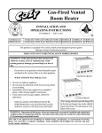
DISASSEMBLY PROCEDURE
The following pictures show the basis chassis. Indiviqual products may be different in details.
I
(
.'
/
1.
REMOVING THE BACK COVER
{1) Unplug the unitfrom the wall outlet.
(2) Remove the two screws (j)from the
bottom, the two screws ® from the
top, and the three screws@from the
rear of th~ set. {Fig. 1-1}
(31 Remove back cover.
(4) Re-assemble in reverse order.
o
CD
NOTE:
(Fig. 1-1)
Tilting the front block by 45°
helps when re-assembling back
cover. (Fig. 1-2)
2. SERVICING THE POWER SUPPLY
BLOCK
(1) Remove the screw@. {Fig. 1-2)
(2) Disconnect power supply Connectors
I, II, III, IV.
(Fig. 2-1).
(Fig. 1-21
NOTE: Connector names are as follows:
I) A.C. Power'Cord Connector.
II) Pow€ r Switch Connector
III) Auto Degaussing Connector.
IV) B Connector
Front
{]'
(3) Remove the screw®and take off the
I. C. holding metal plate <£>. (Rg. 2-1)
(4) Remove the screw@ and slide the
(51
FBT
(Fig. 2-1)
- 11
power supply PWB to the front. (Fig ...•,
1-2, Fig. 2-1)
Reassemble'in reverse order.
3.
PWB MAIN SERVICE . ~fter removing the back cover, follow
this procedure (Fig. 2-1) to allow easy
access to the main PWB.
(1) . Disconnect CRT anode lead@, CRT
Socket ®, Connector coating earth
@, and connector D.Y. (Fig. 3-1)
(2) Remove the two screws@,@.(Fig.
3-2, Fig. 1-2)
(3) Take off the lead clamp (a, b, c, d).
(Fig. 3-1, Fig. 3-2)
. (4)PWB holder m.LJ will open .both side
and pull out the main. PWB.(Fig, 3-2)
(5)' Re-assemble in reverse order.
d
4. PICTURE TUBE REMOVAL
The main PWB must be removed
before attempting to remove the pic- .
. turetube.
c
. (1 ) Loosen the screw @ and remove the
convergence magnet assembly. (Fig.
4-1 )
(2) Loosen the screws @, @ and
remove the Deflection Yoke. (Fig.
4-1)'
.
(3) . Remove the four screws ® at the
corners of the· picture tube and
carefully remove the tube.' (Fig. 4-1)
(4). Re-assemble.in reverse order.
®
®
- 12
,.""-
~."';::;
~-----
\
.1./,."
~;':,~ ';
----'-------_....
;,;;
TO H. O~TPUT CIRCUIT
POWER 0
INPUT
-I
,
I
I
VIDE 0
INPU T
AUTO DEGAUSS
THSOI.
VOLTAGE 5yt1T
I----.~-- TO H. DRIVE CIRCUIT
CHING REGULA TOil
ICSOl,OS20
TO H. FREO. CIRCUIT
I C
R"
COLOR
G
INTERFACE
B_ \
.IC tOl
1"
0140.0141
J
L
L
J
L
flCUIT
+
I
R. BUFfER 0101
G. BUFFER 0131
RED OUTPUT AMP •. 0851.0854
r
GREEN OUTPUT AMP. 0852. 0855
.r-
I
J
I-
~
;~>
B. BUFFER 0161
CRT
I
I
I
I
) I.
I
I
I
.....
W
I'
t-
CONTRAST CON·
TROL VR141
BRIGHT CONTROL
VR140 0171
-
SYNC. I JPUT
H lrHN _
V
...
=t
SYNC.
MIXER
IC102.
,.
SIDE·PCC
CONTROL·
VR640
z
w
w
a:
.'
N:i
H. OUTPUT 0702
tINTERLACING CONTROL
VR301, IC30t, IC302
__
.
u
0
u.
BLANKING
OUTPUT
H.FREO
L--. H. SYNC. IN
V. SYNC. IN
AFC
t
1
500 -900 V
U
5'.6 kV ~
HV
20 kV
75V
V. OUT CIRCUIT
13V
VIDEO AMP.
CUlT
fBT
-H. DRIVE 0701
J
.
::l
200 V
._.
-.9
'H. OEFLE,...",· .... u ,.._.f
~
HIGH
VOLTAGE.
PROTECTION
V. FREO
~
V. OUTPUT0601,
060~
AUTO DEGAUSS
COIL
III
PCT
J
H. SYNC. PULSE
WIDTH
\
REGULATOR
ICl03
'-
(J
III
6 Vrms
BLANKING CIRCU!T
0143
)
~
17'17:
BLUE OUTPUT AMP.
0853,01156
I
,
~
V. DEFLE
BLOCK DIAGRAM
\ [ Version I ]
i
V. FREO CIRCUIT
...
---.'
\.: :
TO H. OUTPUT CIRCUIT POWE~
.1
0
INPUT
AUTO DEGAUSS
TH901
1----1~-. TO H. DRIVE CIRCUIT
VOLTAGE SWIT·
. CHING REGUl.A TOR IC901.0920 TO H. FREO. CIRCUIT
I
C
I
.-
RCUIT
REO OUTPUT AMP. OB51.0B54
CRT ..
VIDE
INPU
-
-
G"
INTERFACE B "
IC 101
I
0140.0141
)
"
j
COLOR
R
1
.f::>.
.1
V
I
I
) I
r-
BLUE OUTPUT AMP.
0853.0856 BRIGHT CONTROL
VR140.0171
I
I
I
I
1
)
I
~F
1)",
zw w
a:
"
I
PIN DISTORTION
CONTROL VR640
PCT
1702
II)
J
en
:>
u
...
a
6 Vrms
Bt.ANKING CIRCUI.T 0143
500 ·900 V
H. OUTPUT 0702
5.6
kV t--
HV
22 kV
tLETTER QUALITY
CONTROL 0301. VR301. IC301. 0302 75 V
200 V • OUT CIRCUIT
VIDEO AMP.
UIT
12 V
FBT
H. SYNC. PULSE REGULATOR IC103 I
BLANKING
OUTPUT
..
_~
L---+ H. SYNC. IN
V. SYNC. IN
..
·H. DRIVE 0701
J
H. FREQ .
AFC
't
" .':.
~:"',
'::11 !
V. FREO
~11 ~
...
••- . . .
..:9
V.OUTPUT0601.
0602
~
t
I ... !'....J,:..· ••!~.-If~:
H. DEFLE--'-" -_ ..
~
FREO CIRCUIT
HIGH VOLTAGE PROTECTION
.'''.,•••. ,.''.........
•
AUTO DEGAUSS
COIL
u
'"'"l SYNC.
MIXER
IC102 ,..
r-
G. BUFFER 0131. GREEN OUT,,;UT
AMP. 0852. 0855
B. BUFFER 0161 I
-
SYNC. INPUT _
HorHN
1
L
CONTRAST CONTROL VR141 ......
1
.
L
~
1
R. BUFFER 0101
,.~'''''
..., .....''' ......- ' ' ' ..
~
V. DEFL
BLOCK DIAGRAM
,.=-......v."" ..'"""''''':.~.lRi.I!t,=..,.:, ...:w...,....,.:I,.·cY-ersion II. 1., .... ••' ' ' . ,....
,':.
.~.
-(.....:... .:,~.r:l!'~~
1. Operation Principles
I
II
'1-1 Voltage regulator circuit
I
I
1
,i
Primary rec·
tification 0901
AC INPUT 0 -
Voltage regulation
ICeOl
Output transformer T901 1
,---I
Secondary
rectification 0940
Voltage detection
Output
+115 V
,
The voltage regulat~:>r circuit of this unit uses a switching regulator system. In other words,
the input AC supply voltage is rectified to'unfiltered DC voltage by the primary rectifier Circuit.
This voltage is converted to high-frequency pulses by the voltage regulator IC (lC90 1) which
simultaneously performs pulse width control for regulation of a secondary rectification output.
The DC output with no ripple {+ 115V) is obtained by the secondary rectifier 0940 following
the passage through the output transformer T901. This IC has a built-in overcurrent protection
circuit.
I
"\'
1-2 Video circuit
\:I,
i:
(1) Color interface circuit
I;
I!
Ii
""
11
I'
i'
Ii
Color setting switch S 101 I:
I
!:
Iiq
Ii
I!
Video input
-
R
Color interl"ce
G
,
,
Contrast control circuit 0140.0141, VR141
"
Blue video buffer 0161
L
~
, +5 V oUtput Q142, Red video buffer 0101
Green video buffer 0131
I
I, "
ABl
~
Blanking output
0143'
1.-
Brighlnessconlrol
VR142 '
+12 V
I
I
~
L
IC101 B
r
-I ,
"i
I
I
To video output
amplifier circuit
I
I
Blanking pulse
The input video signals'R, G, B, I are combined by IC101 into optional colors (e.g. IBM colors,
Apple colors, standard colors) set up by the color setting switch S1 01 and sent to the respec
tive video buffers (0101, '0131; 0161), The output voltage level of the color in~erface ICl 01
''':'-1"5 :.:
I •
(
can be controlled by the contrast circuit of 0140,0141, VR141, which permits screen brightness·
control. The contrast circuit also has an ABL circuit attachment which,prevents
the CRT beam current from increasing abnormally when trouble occurs.
The blanking circuit 0143 and brightness control VR 142 connected between the color in
terface and video buffers are used for blanking and black level control.
(2) Video amplifier circuits
AI
G
From video
R
RED OUTPUT AMP.
0851.0854
G
GREEN OUTPUT AMI(.
0852,0855
buffer circuit
L,
.
,,
j
B
(
To CRT
cathode
B
BLUE OUTPUT AMP.
0853,0856
L
B.K.G control VRS01,
VRI311, VRS21
The R, G, B; video signals composed by the color interface circu"it pass thr·ough the video
buffer circuits and are entered in the respsctive R, G, B video output amplifiers where they
are amplified to about 5b Vp-p for output to the CRT cathode. The background (B.K.GJ
control resister VR801 (red), VR811 (green), VR821 (blue) which serve to fix the CRT
cutoff level are connected between the video output amplifiers and the CRT cathode.
1-3 Vertical deflection circuit
r-l WIDTH
H.SYNC.PULS'
REGULATOR ~
.
To blanking circuit
IC103 ;
I
. II
SY(lC composition
IC102
-I
I
101
8
L
'7
J.
L
Sync:
separator
I
Oscillation
3
61
+7L
Sync: selector
switch S101
bit 5
IC701
J
I
J
I.
V. blanking shaping
J
I
Amplification
J
J
1
4
~603
17
V.lIN
V. SIZE
+12 V
Vertical output
0601. Q602
- 16
VerticalDY
....
The sawtooth oscillating voltage is generated by the' charge and discharge of C603. During
a vertical flyback period,'C603 is charged from pin @ of the IC701 by the switching
transistor inside the IC. During a scanning period, it is discharged by the resistor R602
and the verticallinearlitycontrol VS701 @ connected to·pin @ of the IG. As a result,
the potential slowly decreases. When this potential reaches the same level as that applied
to pin Q) of the IC, the charging starts again by the switching transistor in the IC,
corresponding to the flyback period. Meanwhile, the output voltage applied to the deflection
yoke is amplified by the amplifier circuit inside the IC and. applied to the vertical output
transistor Q601, 0602 from pin CD of the IC. These transistors drive the vertical DY.,
I •• 1.
I
I
Flyback period
~
i
i,
Ii
:1
;
I
I
I
----J Scanning period I
I
I
:!
1-4 Horizontal deflection circuit
IC701 S YNC H 0--
v
0-
10
Sync com·
position IC102 I
I
16
Sync
separator
J
I
f-
l
AFC
11
I
• 12 ~
Oscillation
l,3 ' '
, High·voltage
limit control ---~--
Horizontal
predrive
15
;
t
Sync selector
switch S 101
bit 5
I
L
;
.
Horizontal
drive 0,701
H. SYNC. PULSE
I
"- WIDTH
REGULATOR
L
ICt03
I
Horizontal
output 0702
(1) AFC
Horizontal DY
circuit,
'. The triangular voltage generated from the flyback transformer pulses is applied to pin ®
of the IC701 and the sync signal is applied directly to the AFC circuit from the sync separator
circuit inside the IC. The AFC circuit compares the phase between these signals and outputs
from pin@ of the IC the current proportional to the phase difference. This current is sent
from pin ® of the IC vta the resistor R702 to the horizontal oscillator circuit for oscillating
frequency control.
(2) Oscillator circuit
A triangular oscillating voltage is generated by the capacitors C703,C732. C703 and. C732 are charged via the resistors R703, R704 and th,e H. HOLD control VS701 <D ar)d discharged by the internal circuit of the IC. From this triangula'r wave is created a rectangular wave: with a duty ratio of 1, to 2 which is output from the pin @ of the IC. - 17
•
"(3) Horizontal drive, horizontal ouput circuit
(''.
~.
.
.
Since an approximate 400 mAp-p must flow in the base of the horizontal output transistor
0702, the oscillating voltage is amlifiedby the drive circuit composed of 0701 and T701.
Consequently, a linearly increasing current flows in the coil. VVhen Q702 is non-conducting,
the current previously flowing in 0702 comes to flowinC717, C718, C719 for resonance
with these capacitors and the coil.
Athalf of the resonance cycle, the current direction iSJeversed and the current now flows
through the damper diode (inside 0702)
By making 0702 conducting again while the
current flows in this diode, a periodic sawtooth current is allowed to flow in the horizontal
coil.
+'.
,.
,L"
;/ 't
i r
9
r.
a 702 conduction
Resonance
Damper diode
period
period
conduction period
+11
"
630/640 E, A, 8, J,S
'"
. !."
An approximate 1kVp-p pulse voltage generated by resonance of the capacitors and coil is
boosted by T703 (FBT) and supplied to each CRT electrode, the vertical output circuit, video
circuit, etc.
(4) High-voltage limit control circuit
If a high voltageapplit;d to CRT from T703 (FBT) rises abnormally for some reason and
exceeds approximately 28 kV, the high-voltage detector voltage output from pin 0 of
T703 (FBT) is applied to pin @ of IC701, which stops the output of the horizontal
predrive inside the IC701.
.
;..
-
18
I:
I',
2. Repair Chart
"
{-"
i.· ... ,. . /
"- -
....
Turn on power and connect the input signals.
i
i
I !
; I
,I
' ,i
E
No raster
input voltage
Normal input voltage
(check
+B
I
line, horizontal output circuit)
(check horizontal circuit, CRT circuit)
Only a horizontal line
(vertical circuit)
Only a vertical line
(DY circuit)
,
,;
:; I1
Ii
:i
,
,I
II
The raster appears.
L
:I
No picture
(check
+ 12 V, . + 5 V line,
video circuit)
iI
, "!
Horizontal amplitude
too sma"
(horizontal circuit)
Abnormal vertical
amplitude
(vertical circuit)
Dark screen
.(CRT peripheral circuit, video circuit)
No, horizontal syn
chronization
(AFC, horizontal oscillator circ~it)
sync~roniza
I:
ii
The picture appears.
No vertical
tion
I
(vertical circuit)
Abnormal hue
(color interface circuit, video circuit)
Different luminance
between horizontal and
vertical dots of a
character
(video circuit)
Bad focus
(CRT peripheral circuit)
Bad ,side' distortion
(Side-PCC circuit)
-
19 -
~.
No raster (2): Troubles in the FBTperipheral circuit
No 'raster
Collector pulse of
horizontal output
appeared?
Check horizontal output circuit and
high voltage restriction circuit.
High-voltage circuit. CRT dr- .
cuit fault
. Peripheral parts of Q701. Q702.
peripheral parts of H.OY and
R730. R73a. R737. Z0701.
R736. C734.IC701.
High vohage at anode?
YES
CRT heater voltage normal?
NO ,
Check heater circuit.
YES
i~-'
.. : >~
~.' ..
All FBT. CRT electrode
voltages normal?
Check each electrode voltage:
+ 13 V; 0706 cathode . CRT <31; 0 V
+76 V: 0710 cathode
CRT G2: 500-900 V
+ 200 Vf 0705 cathode CRT G4: 5.6 kV
NO
YES
CRT cathode. voltage normal?
NO
Check video circuit.
YES
Check CRT.
(1)
Red video circUit:
'
R8S1. AS54. RS57. RS7S. VAS01. l854. C85l. CS54.
C857.C803.0854.0851
(21 Green video circuit:
R88~ AS55 •. AS59. RS79. VASll. lSSS. CSS2. C8SS.
C8S8. Cao2; 0855. 0852
.
(31 Blue video Circuit:
A8a3.A856. R86l. R8S0. VR821. La56. C853.C856.
C859. CS01. 0856. 0853
- 20
..
3. Troubleshooting
;
No raster (1): Troubles in the 'power circuit, horizontal deflection circuit
No 'raster
Raster produced when BRIGHT
CaNT. is set to MAX?
YES
Confirm BRIGHT. CaNT.
position.
¢>
Adjust SUB CaNT. VR141.
-
NO
(
Power circuit. horizontal
circuit fault
DC voltage
*11
ac~oss
'
Check primary ree
tifier circuit.
C90n
F901,
0901
NO
+ B voltage normal (115
VOC)?
...
:"
I
IC701@
NO
:
*2) 630/640U:
{}
,YES
Horizontal oscillator circuit
output?
·1) 630/640U: ,170 voe
630/640E, S: 310 voe
630/64?B~ .A: 340 voe
Check + B'control section,
secondary rectifier, circuit.
·31 630/640E. A. B, J, S
I
ICS01. OS40. CS42. 0942
"
"
.!
!
c>
,Check horizontal oscillator
circuit.
"
'I
IC701, VS701 G) C732, '
C703,.R703;R704, F701
I
I
!
rES
0702 base
Horizontal drive circuit
output?
NO
Check horizontal drive '
circuit;
¢
R723
R720, R721, R722,R731, R732,
R724; 0701, nOl, C709, C710,
C7S0, 0720, Z0702. 0721*21.
0722*21, 0723*21. R731 *31
YES
,Check horizontal output
" circuit.
¢>
0702, C7l1, C717. C71a. e719, C720, L701, OY,
FBT, L702. L703
-
21
l
"t
Only a horizontal line
Only a horizont.al line
Vertical defletlon circuit
,
.'
!
Service switch 5601 turned
OFF?
NO
Turn OFF service switch S601. !
i
t.
YES
f
{
,i
Vertical osciUator circuit
oscillating? IC701 (j)
0602 @
IC701. C603. CSOS. C604. CG17•
. C61S. R607. Z060l. Ra03.
R604.VS701 @~ZOS02
Check vertical
oscillator circuit.
YES
, Vertical output circuit output?
Check vertical output
circuit.
~
..,........ oaOl. Oa02. 0601. 0602. R6ll. RalS. C61S. R619. R62l. R6H.
C607.,Ca08. CG09. CS11. R606.
VS701 @D.VS701 ~. RSOS. R618
f
if:
.
f
YES
Check deflection yoke.
- 22
;
Nopictul'e
i
No picture
I
I
I
;
Set BRIGHT. CONT. to
Check signal source and
signal cables.
MAX.
i
I
0142
Input signal fully entered?
+5 V power circuit
normal?
YES
Check video circuit.
Check. + 5 V circuit
YES
Check IC10l peripheral
circuit.
Q142.ZD140.Rl44.C142.
C143
IC10l output (01 to Oa)?
YES
:...i'14O
0141
Contrast circuit input/output
voltages normal?
NO
Check contrast peripheral circuit Including 0140. 0141. VR141. YES
Q143
Blanking circuit input/output
voltages normal?
..101
0131
0161
-NO
Cheek blanking cin:uit.
r;>
014~ Dl0L D13LD16L
R145. R146. ~147. C113
YES
Video buffer· circuit in
put/output voltages normal?
NO
Check video buffer circuit including 0101. 0131. 0161 and
VR142
bright peripheral circuit.
1110
Check video output peripheral circuit including .
0851 to 0856.
YES
0851
0856
Video output ,circuit output?
YES
Cheek CRT.
,23
I
I
PARTS LIST •. for Version 1 /*. for Version 2'
No.
Symbol no.
Component
Ratings
Parts no.
,.,'
i
t, '
1
2
3
4
5
6
7
8
9..
..
.
10 11 12
13
14
15 16 17
"
18 ..
19
,20
21 22 23
24
25
R723, R731
R640
R641
R721, R884, R886
R8a7, R888
Resistor
R885
R173, R175, Rl77 '
Resistor
R103, R113, R114
Resistor
Resistor
R133, R163, R173
R611, R732, R872
Resistor
Resistor
R873, R874,' R801
Resistor
R811, R821
Resistor
R606
Resistor,
,11752,
R140
..
Resistor
R149
" Resistor
R302", R309·
Resistor
R104, Rll1, RI05
Resistor
R134, R135, R136
.. . Rl~4, R165,R166 ,
Resistor
Resistor
R174, RH6, R178
...
Resistor
R180, R183, R184
Resistor
R185
Resistor
Rl07, Rqe; R124
Resistor
R169, Rl72. H60e
R304·, R305·
Resistor
Resistor
R154, R156, R158
Resistor
RI0S, R727
Resistor
R302*
Resistor
.R106, R138. R142
Resistor
R143, R144, R153
Resistor
R155, R157, R168
Resistor
R619, B625, R707
Resistor'
R305*
R736
.. Resistor
Resistor
R137, R167, R753
Resistor
R753
Resistor
R147, R605, R704
Resistor
R102, R132. R162
Resistor
R192
..
Resistor
R30S·, R303·, R306
RlOl, R131, R161
Resistor
Resistor
R191
Resistor
R604
Resistor
R120
Rl11, R112
Resistor
Resistor
R119, R12,., R123
Resistor
R708, R608
Resistor
R754
, Resistor
R931
Resistor
R715, R622
Resistor
R703
R612 ,
Resistor
Resistor
Resistor
. Resistor
Resistor
, Resistor
'
,
3.9 ohm,
18 ohm,
22 ohm,
47 ohm,
47 ohm,
56 ohm,
68 ohm,
100 ohm,
,100 ohm,
100 ohm,
100 ohm,
100 ohm,
180 ohm, '
270 ohm, .
270 ohm,
270'ohm,
270 ohm,
,270"ohm,
. 270 ohm,
270 ohm,
' 390oh.m,
390 ohm,
. '470 ohm,
470 ohm,
470 ohm,
680 ohm,
820 ohm,
lk ohm;
1k ohm,
lk ohm,
lk ohm.
lk ohm,
1.5k ohm,
1.8k ohm,
2k ohm,
2k ohm,
2.2k ohm,
2.2k ohm,
2.2k ohm,
2,.2k ohm,
3.3k ohm,
3.3kohm,
4.3k ohm,
4.7k ohm,
4.7k ohm,
4.7k ohm,
4.7k ohm,
5.1 k ohm,
5.lk ohm,
5.6k ohm,
' 6.8k ohm,
S.2k ohm,
- '24
Carbon film
118 W,
Carbon film
1/8 Wi
lI8 W, ' Carbon film
Carbon film.
118 W,
Carbon film
1/8 W,
Carbon film
1/8 W,
Carbon film
1/8 W,
Carbori' film
1/8 W,
Carbon; film,
1/8 W,
Carbon film
1/8W,
Carbon film
1/8 W,
Carbon film
1/8 W,
1/8 W, ,. Carbon film
.1/8 W, , Carbon film
Carbon film
1/8 W,
Carbon film '
1/8 W,
Carbon film
1/8 W,
Carbon film
1/8 W,.
1/8 W,
Carbon
film
.. ..
Carbon film
1/8 W,
1/8 W,
Carbon film
Carbon film
1/8W,
Carbon film
1/8 W,
Carbon film
118 W,
Carbon film'
1/8 W,
. 1/8 W,
Carbon film
Carbon film
'118 W,
1/8 W,
Carbon film
118 W,
Carbon film
Carbon film
1/8 W,
Carbon film
1/8 W,
1/8 W,
Carbon film
118 W,'
Carbon film
1/8 W,
Carbon film
118 W,
Carbon film
Carbon film '
118 W/
Carbon film
1/8W,
118 W,
Carbon film
Carbon film
1/8 W,
,1/8 W,
Carbon film
.Carbon film
1/8 W,
1/8 W,
Carbon film
Carbon film
1/8 W,
Carbon film
1/8 W,
Carbon film ,
1/8 W,
Carbon film
1/8 W,
,Carbon film
1/8 W,
Carbon film
1/8 W,
1/8 W,
Carbon film
1/8 W,
Carbon film
1/8 W, Carbon film
lIS W, Carbon film
.
Remarks
.'
0100607 01000023G 01000025G
01000033
01000033
01000035 '
01000037
.'
01000041 01000041 01000041
01000041 ' ...
01000041 01000047 01000051
01000051F
01oo0053G·
01000053
..
010000q3 01000053 01000053
01000055
01000055
01000057
01000057
01000057G
01000061
,01000063
01000065F
01000065
01000065
01000065
01000065
01000069G
01000071G
01000072
01000072G
01000073
01000073
01000073 ..
:01000073G
'01000077 01000077
01000080 01000081F 01000081 01000081 01000081 01000082 . 01000082G 01000OS3G 01000085 01000087 .
'.
,
, t
I
"
.' PARTS LIST •. for Version 1 1*' for Version 2
No.
. Component
26
Resistor
Resistor
Resistor
Resistor
. Resistor
Symbol no• Ratin~,
Parts no.
Rem.arks
/
\
27
28
29
30
31
32
33
34
35
36
37
38
39
40
41
42
43
44
45
46
47
48
49
,
50
51
52
53
_54
55
56
57
58
59
60
. 61
62
63
64
65
66
67
68
Resistor
Resistor
Resistor
Resistor
Resistor
Resistor
Resistor
Resistor
Resistor
Resistor
Resistor'
Resistor
Resistor
Resistor
Resistor
Resistor
Resistor
ReSistor
Resistor·
Resistor
Resistor
Resistor
Resistor
Resistor
Resistor
Resistor
Resistor
Resistor
Resistor
Resistor
Resistor
Resistor
Resistor
Resistor
Resistor
Resistor
Resistor
Resistor
Resistor
Resistor
Resistor
Resistor
Resistor
Resistor
Resistor
Resistor
Resistor
R145. R146. R711
R308*
R603. R929
R301"
R737
R607· .
R602
R935
R706
R115 .
R725
R857. R859. R861
R878, R879, RB80
R726
R930
R610
R860. R86~
R129
R928
R881
R883
R882
R722
R92l
R728
R734
R738
R730
R723
R723·
R309*
R858
R620
R854. R855. -R856
,R631
R633 R926. R927
R630. R632
R618
R615, R616
R955, R956
R733
R923
. R924. R925
R920
H922
,R851. R852, R853
, R875. R876, R877
. R832
R802
RnO
R701
10k ohm.
10k ohm,
13k ohm.
15k ohm.
15k ohm.
18k ohm.
22k ohm,
22k ohm.
33k ohm,
75k ohm.
150k ohm.
l80k ohm.
180k ohm,
270k ohm.
4.7 ohm,
8.2 ohm;
100 ohm.
680 ohm~
lk ohm,
1.8k ohm,
2.2k ohm,
2.7k ohm.
3.3k ohm.
3.9kohm.
6,8k ohm,
6.8k ohm,
30k ohm,
39.k ohm,
3.9 kohm
3.9 kohm
4.7 ohm, .
·39 ohm,
56 ohm,
150 ohm.
470 ohm.
470 ohm.
470 ohm,
680 ohm.
l.lk ohm,
3.3k ohm.
4,7Mk o,hm.
18kbhm,
68k ohm.
120k ohm,
1 ohm.
39 ohm,
910 ohm.
910 ohm,
3,3k ohm,
8,2k ohm.
3.3k ohm.
5.6k ohm,
-25
Carbon film
118 W.
1/8 W.
Carbon film
Carbon film
1/8 W.
1/8 W •
C~rbon film
1/8W.
Carbon film
1/8 W.
Carbon· film
l/8W,
Carbon film
1/8 W,
Carbon film
Carbon film .
1/8 W.
1/8 W.
Carbon film
Carbon film
1/8 W.
Carbon film
1/8 W.
Carbon film
1/8 W.
Carbon film
1I8W.
Carbon film
114 W.
1/4 W,
Carbon film
Carbon film
1/4 W.
1/4 W,
Carbon film
1I4W,
Carbon film
Carbon film
114 W.
114 W,
Carbon film
1/4 W,
Carbon film
Carbon film
114 W.
Carbon film
1/4 W.
1/4 W,
Carbon film
Carbon film .
114 W,
114 W.' Carban film
1/4 W;
Carbon film
Carbon film
1/2 W,
Carbon film
1/2 W.
Carbon film 1/2W.
Carbon film
112 W.
Carbon film
112 W.
Carbon film
112 W.
Carbon film
112 W.
Carbon film
1/2W.
Carbon film
112 W,
Carbon film
1/2 W,
Carbon film
1/2 W,
Carbon film
1/2 W.
1/2 W,
Metal.
Metal oxide
1 W.
Metal oxide
lW.
1 W,
Metal oxide
Metal oxide
2W.
2W,
Metal oxide
Metal oxide
2W.
Metal oxide
2W.
_ Metal oxide
2W,
Metal oxide
2 W~
Metal oxide
5W.
..
Metal oxide
5 W,
01000089
01000089,G
01000092
F020084T
Q1000093G
01000095G
01000097
01000097G
01000101
01000110
01000117G
01000i19G
01000119G
01000117
01140Q9T
011.4015
0114131T
0114151
0114161T
0114167T
0114169T
011'4171T
0114173
_0114175T
0114181T
0114181
0114212
0114215
F020014T
0100007
F020088T
F020038G F020042 F020052G F020064 F020064T
F020064G
F020068
F020073G
F020084
F040201
0110175
F040023
F040022
F040033
0110211
0110244G
0110244G
0110257G
0110267G
F040042
F040041
U
EABS
PARTS LIST *;
No.
Component
69
70
71
72
73
74
Resistor
Resistor
Resistor
Resistor
Resistor
Resistor
75
76
77
78 .
79
80
81
82
83
84
85
86
87
88
89
90
91
92
93
94
95
96
97
98
99
100
101
102
103
104
105
106
107
108
109
110
111
112
113
114
Volume
Volume
Volume
Volume
Volume
Volume
Volume
Volume
Volume
Volume
Volume
Volume
Volume
Volume
resistor
resistor
resistor
resistor
resistor
resistor
resistor
resistor
resistor
resistor
resistor
resistor
resistor
resistor
Capacitor
, Capacitor
Capacitor
Capatitor
Capacitor
Capacitor
. Capacitor
Capacitor
Capacitor
Capacitor
Gapacitor
Capacitor
Capacitor
Capacitor
Capacitor
Capacitor
Capacitor
. Capacitor
Capacitor
Capacitor
Capacitor
Capacitor
Capacitor
Capacitor
Capacitor
Capacitor
Capacitor·
Capacitor
Capacitor
Capacitor
Symbol no.
. R724
R901
R901
R148,R621
R634,' R718, R740
R719, R755
VR742
VR142
VR141
VR140
VR920
VS701
VR640
VR628
VR301'
VR301*
VR801
VR8'1
VR821
R864, VR865
C140
C864
C734
C926, Cll1
C144, C746, C701
C613
C614
C716, C611
C145'
C142 C141, C702, C601' *
C305', C306, C707
C920
C737
C607
C921
C606
C301 ~, C302*
C305*, C309*
C608
C609,C740
C854, C855, C856
C867
C724, C744
C942
C910
C910
C801, C802,C803
C714
C860
for Version 1 1*: for Version 2
Ratings
5..6 ohm,
3.9 ohm,
15 ohm,
10 ohm,
1 ohm,
2.2k ohm,
500 ohm,
500 ohm,
lk 9hm,
5k ohm,
50k ohm,
6-VR,
100 ohm,
lk ohm,
500 ohm,
20k-B,
50k ohm,
. 50k ohm,
50k ohm,
200 ohm,
_10 /LF,
22/LF,
33 /LF,
47/LF,
100/LF.
220/LF,
330/LF,
470'/LF,
1000 JLF,
47 /LF,
1 /LF,
1 /LF,
2.2 "F,
3.3 /LF,
4.7 /LF,
22 /LF,
33 /LF,
, 100 /LF,
10000 JLF,
10 I'F,
100 /LF,
4.7I'F,
10 jLF,
100/LF,
100/LF,
470 JLF,
220.I'F,
4.7 I'F,
1Ol'F,
150 pF,
-
26
Parts no.
5 W,
8 W,
8W,
1/4 W,
'114 W,
1/4 W,
Wire wound
Wire wound
Wire wound
Fusible
Fusible
Fusible
.
1/2 W,
Wire wound
1/2 W,
Carbon film
Carbon film
112 W,
Carbon film 0.1 W,
Carbon film
0.1 W,
Carbon film
0.1 W,
Metal
1/2 W,
1/2 W, - Metal
Metal
112 W,
Metal
1/2 W,
Metal
1/2. W,
Metal
1/2 W,
1/2,W,Metal
1/2 W,
Metal
16 V, 16 V,
16 V,
lG V,
16 V,
16 V,
16 V,
16 V,
16 V,
25 V,
50 V,
50 V,
50 V,
50 V,
50 V,
50 V,
50 V,
50 V,
- 50 V,
100 V:
100 V,
160 V
160 V,
160 V,
160 V.200 V,
400 V,
250 V,
250 V,
50 V,
ElectrolYtic
Electrolytic
Electrolytic
Electrolytic
. Electrolytic
Electrolytic
Electrolytic
Electrolytic
Electrolytic
Electrolytic
Electrolytic
Electrolytic
Electrolytic
Electrolytic
Electrolytic
Electrolytic
Electrolytic
Electrolytic
Electrolytic
Electrolytic
Electrolytic
Electrolytic
Electrolytic
Electrolytic
Electrolytic
Electrolytic
Electrolytic
_Electrolytic
Electrolytic
Ceramic
F070011
0141073
F070051 0119514
0119512
0119505
0162626 F090121
F090123 F090102
F090103
F090111
F090151 F090092 F090152 F090153 F090033 F090034 F090035 F09006' F190317F F190318F F190319 F190320F F190321F F190322F F190323
F190342F
F1S0325F
F190333F
I .- Fl 90355F
F190355F
F190356
F190357F
F190358F
F190360F
F190361 F
0248724F
0244171F
F190384F
F190388F
0253455F
F190404F
F190281F
F190408F
F190551
F190561
F190412F
F190413F
0244229F
Remarks
U
EABS
Block
type U
E.A.B,S
I
I
PARTS LIST *. for Version 1 1*" for Version 2
No.
Component
Symbol no.
Ratings·
Parts no.
'.
115
116
117
118
119
120
121
12
123
124
125
126
127
128
129
130
,'-;"'" 131
~y
13Z
133
134
135
136
137
138
139
140
141
142
143
144
145
146
147
148
149
150
151
Capacitor
Capacitor
Capacitor
Capacitor
Capacitor
Capacitor
Capacitor
Capacitor
Capacitor
Capacitor
Capacitor
Capacitor
Capacitor
Capacitor
Capacitor
Capacitor
Capacitor
Capacitor
Capacitor
Capacitor
Capacitor
Capacitor
Capacitor
Capacitor
Capacitor
Capacitor
Capacitor
. Capacitor
Capacitor
Capacitor
Capacitor
Capacitor
Capacitor
Capacitor
Capacitor
Capacitor
Capacitor
Capacitor
Capacitor
Capacitor
Capacitor
Capacitor
Capacitor
Capacitor
Capacitor
Capacitor
Diode
Diode
Diode
Diode
Diode
C861
180 pF,
C862
220 pF,
Ce18, C304
560 pF,
C617
680 pF,
C704
2200 pF,
C143, C151, t152
0.01 p.F,
C153, C154, C155
0.01 p.F,
C122, C602, C86S
0.01 p.F,
C867, C870
0.01p.F,
C902, C903
1000 pF,
C904, C905, C906
4700 pF,
C907, C955, C956
4700 pF,
C612
180 pF,
C709
·220 pF,
C710
820 pF,
C7l2
.1000 pF,
C6l0
4700 pF,
C851, C852, C853
4700 pF,
C857, C85S, C859
4700 pF,
C866
4700 pF,
C923, C927, C944
1000 pF,
C805
1500 pF,
C925
1500 pF,
C924
3300pF
C182, C183, C184
47 pF,
C185
47 pF,
C603
1 pF,
C113
33 pF,
C730
33 pF,
Cll0
120 pF,
C940
180 pF,
C7l1
330 pF,
C703
5600 pF,
C722
2200 pF,
C706
0.01 p.F,
C705
0.015 p.F,
C302·, C303·, C604 0.022 p.F,
C713
0.022 p.F,
C605, C731
0.033 p.F,
C301·, C922
0.047 p.F,
C901
0.1 p.F~
C780
0.033 p.F,
0.1 p.F, .
C723
C721
0.12 p.F,
C719
0.01 2 p.F~
Cl17, C718
0.01 p.F,
.
0101,
0103,
0105,
0112,
0114,
0102
0104
0111
0113
0131
US1040,
US1040,
US1040,
US1040,
US1040,
- 27
50
50
50
50
50
50
V,
V;
V,
V,
V,
V,
Ceramic
. Ceramic
Ceramic
Ceramic
Ceramic
Ceramic
Ceramic
50 V"
50 V,
Ceramic
50 V,
Ceramic
125 V,
Cetamic
400 V,
Ceramic
400 V,
Ceramic
Ceramic
500 V,
Ceramic
500 V,
Ceramic
500 V,
Ceramic
500 V,
Ceramic
500 V,
Ceramic
500 V,
500 V,
Ceramic
Ceramic
500 V,
1k V,
Ceramic
lk V,
Ceramic
lk V,
Ceramic
lk V,
Ceramic
Ceramic
50 V,
.50 V,
Ceramic
25 V,
Ceramic
Ceramic
50 V,
500 V, . Ceramic
50 V;
Ceramic
2500 V, .Ceramic
Ceramic
2500 V,
50 V,
Polyester
50 V,
Polyester
Polyester
50 V,
Polyester
50 V,
Polyester
50 V,
50 V,
Polyester
50 V, . Polyester
50 V,
Polyester
. Polyester
125 V,
Polypro
100 V,
. 200 V,
Polypro
Polypro
200 V,
.Polypro
630 V,
Polypro
630 V,
Silicon Silicon Silicon Silicon Silicon film
film
film
film
film
film
film
film
film
0244116F
0244230F
0244115F
0244117F
0244105F
0244171F
0244171F
0244171F
0244171F
F150261
0249159
0249159
F16oo33F
F16oo34F
F160041F
F160042F
F16oo50F
0244565F
0244565F
0244565F
F160102
F150453
F160104
F160108
0248676
0248676
0292706F
0248676
F160078F
0244228F
0243839
0243837
0279211F
F150102F
F150118F
F150122F
F150126F
F150126F
F150130F
F150134F
F150244
0299037F
0299926F
0299927F
0299982F
0299981F
F380201
F380201
F380201
F380201
F380201
Remarks
-j
I
II i
U
U
PARTS LIST'
No.
Component
,.
152
153
154
155
156
157
158
159
160
161
162
163
164
165
.
Diode
Diode
Diode
Diode
Diode
Diode
Diode
Diode
Diode
Diode
Diode,
Diode
Diode
Diode,
Diode
Diode
Diode
Diode
Diode
. Diode
Diode
Diode
Diode
Diode
Oiode
Diode,
Diode
Diode
Symbol no.
176
177
,178
179
180
181
182
183
184
185
Zener
Zener
Zener
Zener
Zener
Zener
Zener
Zener
Zener
Zener
diode
diode
diode
diode
diode
diode
diode
diode
diode
diode
IC ..
IC
IC
IC
IC
IC ."
IC
IC
-
Transistor
Tral1sist9f
Transistor
Ratings
0132. 0133
US1040,
0134, 0135
US1040,
0136,0140
US1040.
0141. 0161
US 1040,
US1040,
.0162, 0163
0164,0165
US 1040.
D166.0191
US1040.,
D192, D601
US1040,
0602, D702
US1040,
US1040,
D703. D718
D719, D115
US1040,
.0603
US1040,
US 1040,
D301, D302*
0707
US1090,
0710
AU1,
0705
AUlA,
D706
RH1S.
0714, 0715
V06C,
0854. 0855. D856 ' V06C,
V09C, "
0721
0851, D852, 0853
lSS82,
SEL1324G,
0120
0720
EU02,
0724,·0940
AU2AM,
0922
' GFE10,
D722, D723
GFElOR.
OFC 10,
D920, 0921
0901
RB-156LFB;
"
,
166
167
168
169
170
171
172
173
174
175
•• for Version 1 I*-for Ve'
rSlon 2
Parts no.
Silicon
Silicon
Silicon
Silicon.
Silicon
Silicon
Silicon
Silicon
Silicon
Silicon
Silicon
Silicon
Silicon
Silicon
Silicon
Silicon
Silicon
Silicon
Silicon
Silicon
Silicon
silicon
Silicon,
Silicon
Silicon
Silicon
Silicon
Silicon
F380201
F380201
F380201
F380201
F380201
F380201
F380201
F380201
F380201
F380201
F380201
F380201G
F380201G
F380631G
F380651
F380652
23322~1
2330251
F360281
2330551
2331912
F530061
F410551
IC10l
IC102
' IC103
IC701
IC301*,
IC301,*
IC901
IC302*
0701
0101,0131,0301
0161, Q140, 0171
HZ483
HZ6LB2
HZ2Bl
HZ-12B-2
HZ-36@
AD5.1EBl
HZ-7 AlB
' HZ-15-:-1
GZS-3.6 B/C
R2M
F380427
2332221
F380378
2331845
F380616
2334122
2330634.
F380575
F380681
F380741
MB7124 or 7123 HIE
M074LS86P
MB74LS 123M - G
HA11423
MB74LS132M-G
74lS73
STK-7308A
MB74LS74AM - G
F4lO791
2361881
F410694
2364181
F410697
F410673
F410592
F410674
2SC2271 MIN
2SC458 C/D
2SC458 CID
2321992
2320596
2320596
- 28
U
F4105~1
F380661
F380751
F380681
F410541
.
Z0702
Z0140
Z0103ZD302*
ZD701, Z0301*
ZD601, Z0602
Z0101
Z0102
Z0920, ZD921
Z0941
Remarks
U
PARTS LIST
•. for Version 1 /*. for Version 2
No.
Component
Symbol no.
186
Transistor
Transistor
Transistor
Transistor
Transistor
Transistor
Transistor
Transistor
Transistor
0143,0854
0855,0856
0142
0851,0852, 0853
0702
0601,0602
0920
0141
0702
Ratings
Parts no.
Remarks
( ',"
CO
187
188
189
190
191
192
193
U
E.B.A,S
Coil
Coil
Coil
Coil
Coil
Coil
Coil
Coil
Coil
Coil
Coil
Coil
L701
L708.
L141,
L710
L901,
L702
L703
L854.
L851,
L853
L151,
L154,
204
205
206
207
Transformer
Tra nsformer
Transformer
Transformer
T701
T702
T901
T703
H. DRIVE
Pin cushion transformer
Switching transformer
Flyback transformer
2260071 F330041 F290074 F310053 208
209
210
Switch
Switch
Switch
S101
S601
S102
DIP switch
SLWK22
Multiple switch J - K2188
F470081 F470031 F470051 211
Connector
. CN101
TCS4480-01-1011
F500051
212
213
Thermister
Thermister
TH901
TH901
PTC thermister 120 V PTC thermister 200 V F400001
2340471
E.B.A,S
214
215
216
Fuse
Fuse
Fuse
F701
F901
F901
Fuse TSCR 0.63 A
Fuse ST3 3.15 A
Fuse SET 3.15 A
F690031
2720902
2720402
E.B.A.S
194
195
196
197
198
199
200
201
202
203
.~.;.
F360281
F360281
F360141
F360151
F360341
F360121
F360231
F360161
F360171
2SC655C/o
2SC655C/o
2SC3179Y/G
2SC2911 (Sm 2SC3026 2So386A 2S01207 2So468C 2S01397 ,
L724
L745, L857
L902
L855, L856
L852
L152, L153
L155
.
Heater choke coil 0.35 "H
Filter coil 22 "H
Filter. coil 100 "H
Filter coil 3300 "H
Line filter
H. SIZE
H. LIN
4.7 "H Axial 10 "H Axial 100 JLH Axial 100 "H Axial 100 "H Axial .
.
-29
"
2120333 2122094 2120482 2120484 F330051 F320043 F320052 2122235T
2122239T
2122253T
2122253F 2122253F Ii
I.
I'
j:
I!
U
U