1
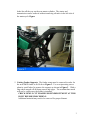
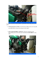
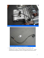
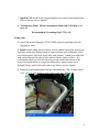
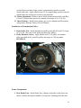
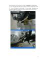
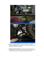
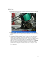
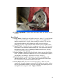
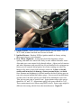
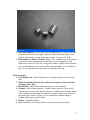
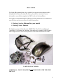
DISCLAIMER
We Highly Recommend that only a qualified or experienced technician with a
background in Harley-Davidson® motorcycles and the American Custom
aftermarket successfully complete the SMW wide tire kit installation.
It is highly recommended that the following H-D® publications are available for
your reference as they are referred to in the instructions.
Factory Service Manual for your model
Factory Parts Manual
We highly recommend that the entire SMW Wide Tire Kit be installed and
“mocked up” for fitment and function. After mock up is complete, SMW fender
and swingarm can be removed and painted to match the tank and front fender.
PARTS NOT INCLUDED
ADDITIONAL PARTS REQUIRED NOT PROVIDED WITH THE SMW
300™ KIT
1
REAR WHEEL WITH 300mm TIRES, PULLEY, AND ROTOR:
Any 10.5” wheel from SMW is fully compatible with the SMW wide tire kit. You
may use your existing rotor and pulley in conjunction with a solid 10.5” SMW
wheel. You may also consider purchasing a matching set of chrome or polished
SMW wheels with rotors and a pulley. Other wheel companies may also be
compatible.
EXHAUST SYSTEM:
Install Right Side Drive exhaust only. SMW has tested and validated fitment of
exhaust systems from several manufacturers. However, Martin Brothers Exhaust
Systems are highly recommended for look and function.
REAR TAILLIGHT/LICENSE PLATE ASSEMBLY:
We recommend taillights that will mount to the swingarm, foot peg, or derby
cover. We recommend the Eddie Trotta of the Doss swingarm mount assembly.
REAR BLINKERS:
Stock blinkers can be used, however cosmetically Chris Products or Adjure
Blinkers are recommended.
SEAT:
Most solo seats that fit a 13” rear fender work fine. However, only the Drag
Specialties solo seat 05-905138 has been validated for fitment.
STOCK BIKE DISASSEMBLY
It is recommended, to compliment these instructions, to have a Harley-Davidson®
service manual for your particular year model.
1. Disconnect and remove the battery.
2. Drain Fluids: Completely drain the transmission and primary drive oils
need to be completely drained. Refer to H-D® Factory Service Manual.
3. Stabilize and elevate the rear wheel and make safe. Keep rear wheel off of
the ground by positioning the bike on a suitable jack or bike lift.
4. Disassemble: Remove the transmission, seat, primary drive housing, clutch
components, rear tire, swing arm, exhaust pipes, fender, and wiring housing
by unplugging wires and removing two mounting bolts then transmission.
Refer to the factory service manual. Also, remove the rear brake caliper and
2
brake line all the way up the rear master cylinder. The starter and
transmission can be removed without removing oil tank via the left side of
the motorcycle. Figure
5. Cutting Fender Supports: The fender struts must be removed in order for
the new SMW fender to fit. Refer to Figure 2. Use a reciprocating saw or
abrasive cutoff wheel to remove the supports as shown in Figure 2. With a
flap wheel smooth off all sharp corners and edges. The resultant bare metal
will not be visible once the fender is installed.
CHECK NEWLY CUT FRAME FOR FENDER FITMENT AT THIS
POINT BEFORE PROCEEDING.
Additional material may need to be removed for proper fitment.
3
As an anti-corrosion measure, paint the exposed bare metal with primer and/or
paint.
6. Cleaning threads on frame: To aid in the assembly process use a tap and
tap cutting fluid to clean out the threads of the fender .
7. FINAL DISASSEMBLY CHECKS: With the completion of the
disassembly process, the motorcycle should look like FIGURE 3 on this
page.
4
Transmission:
Before installing the transmission you can install a shock lowering kit
(supplied). BC 49-5059
Disassemble shock per factory service manual per factory service manual. A
hydraulic press will be required. Install lowering kit per provided lowering kit
instructions inside kit packaging. Reinstall shocks. Shocks can be adjusted
anytime after this point for proper ride height.
1. Pulley Cover: The pulley cover and actuator assembly must be removed
from the transmission, and then remove pulley nut and pulley. Set the
pulley cover and pulley aside.
2. Speed Sensor: Reinstall on the new provided transmission the stock speed
sensor from old transmission with spacer provided in kit. This is for proper
sensor to gear clearance. FIGURE4.
5
3. Starter: Install starter using the alignment dowel installed on the
transmission as a guide. Use factory bolts for starter with a 5/16” -18 nut
to hold starter into position. Do not over tighten, because the nut will be
6
discarded later during assembly ) FIGURE 5.
4. Transmission: Install transmission through the left side of bike, rear end
first. Make sure the clutch actuator rod does not fall out. FIGURE 6 & 7.
Maneuver transmission into position by first sliding back of transmission
through rear frame opening of bike then move the transmission to the
motor. Refer to factory service manual for torque specs. and sequence of
bolting transmission to motor.
7
5. Ignition Coil: Install frame support/ignition coil to frame and transmission.
Refer to factory service manual.
6. Transmission Fluid: Fill the transmission fluid with 22-24 fluid oz of
gear oil.
Recommended: Screaming Eagle™ 20w 50
Swing Arm:
1. Install Electronics Housing (70354-03HD) with two mounting bolts and
plugging in wires.
2. Install: Install swing arm per factory service manual reusing the stock pivot
shaft bolt, stock pivot bearing (must be removed from stock swingarm), stock
pivot shaft spacers, and stock shock bolts with washers. Install pivot shaft bolt
with washer through left side of bike with the factory spacer in place. It is
recommended that you hold left side of pivot bolt so that the bottom of the
head is horizontal while you torque the right side to proper torque specs.
Reinstall factory shock bolts and washers per factory service manual.
3. Install provided splash guard with provided hardware *X4 (Chrome button
5/16- 18 X ¾), Flat washers, lock washers and nuts. Figure 10.
8
Primary:
1. Shifter Linkage Arm: Install forward control factory shifter linkage to
transmission shifter arm.
2. Removal: Remove the 5/16” – 18 Nut on starter that was previously
installed for transmission installation. Discard nut.
3. Starter Coupler: Install stock starter coupling so that the shallow side of
the counter bore is facing out. FIGURE 11.
4. Wiring: Route all wiring to transmission and starter. Neutral switch
harness is routed under starter assembly.
5. Inner Primary: Install inner primary per service manual. After installing
inner primary, shift transmission by hand through the gears to make sure
linkage will not hit the inside of the inner primary.
6. Starter: Bolt to inner primary per factory service manual.
7. Starter Jackshaft: Install starter jackshaft assembly per service manual.
8. Anchor Plate: Use (Red Loctite™) and torque anchor plate to 12-14 ft .-lb.
or 16.3 – 19.0 nm.
9. Chain Tensioner Shoe: Install tensioner shoe and bolt in place loosely at
this time.
10. Primary Chain & Clutch Basket: Install compensating sprocket, chain,
and clutch basket. (Do not use thread sealant at this time?) Torque
compensating sprocket and clutch basket nut per factory service manual.
Tighten chain.
11. Primary Chain Alignment: Complete a sprocket alignment check. Refer
to factory service manual. Once verification of correct alignment has been
9
verified loosen primary chain, remove compensating sprocket nut and
clutch basket nut. Apply (Red Loctite™) to compensating sprocket nut and
clutch basket nut and torque to factory specifications.
12. Chain Adjustment: Remove and re-install chain tensioner bolt with (Red
Loctite™), adjust chain per service manual, and torque to 21-29 ft.-lbs.
13. Outer Primary: Install outer primary per service manual and fill primary
with primary fluid per Factory Service Manual.
Installation of Transmission Pulley:
1. Drive Pulley Nut: Install transmission pulley using (Red Loctite™) torque
to 70 ft. lbs. (The step on the pulley nut must face pulley.)
2. Pulley Retainer Screws: Apply (Red Loctite™) to pulley nut retainer
bolts (provided in kit), install in pulley and torque to 100 in-pounds.
FIGURE 12.
Frame Components:
1. Rear Brake Line: Install brake lines, fittings, and brake switch from rear
master cylinder through the middle of swing arm. (Running the brake line
10
along the frame as the original was located.) FIGURE 13, 14, 15, & 16.
Use a 28” flexible brake line from the master cylinder to brake light switch
‘T’. Use a 34” flexible line from brake ‘T’ to rear caliper. Routing the line
through the left of the swing arm to later be placed in the ‘notch’ in the
provided SMW™ splashguard.
11
2. Brake Tee: Tighten Brake Stop Switch to Brake Tee installed on
transmission (Figure 16). Install stock switch wiring to brake switch.
Terminal direction is not important.
3. Speedometer Re-Calibration: Install the provided speedometer recalibration box between the speed sensor harness and the speed sensor.
(See Speedo Re-cal box for instructions and adjustment info.)
12
Pulley Cover:
1. Rear Belt: Install rear belt around the transmission pulley and through
the swing arm. Figure 17
2. Pulley Cover: Apply (Blue Loctite™) to pulley cover bolts and then
reinstall pulley cover. Torque the bolts to 200 in-lbs. (3pc 5/16-18 x 1”
Bolts.)
3. Mechanical Clutch Actuator Cover: Remove the outer mechanical
actuator cover with gasket from chrome pulley cover. Install stock
clutch cable through chrome actuator cover. (Do not over tighten clutch
cable to actuator cover) Hook cable end to ball and ramp assembly.
Make sure you seat ball and ramp properly in actuator cover. FIGURE
18. Apply (blue) thread sealant to actuator cover bolts and reinstall
actuator cover with gasket to chrome pulley cover. Torque to 110 inlbs. Add grease.
13
4. Clutch Adjustment: Adjust clutch and clutch cable per factory service
manual.
Rear Wheel:
1. Rear Wheel: Install rotor and pulley onto rear wheel. Use (red) thread
sealant on rotor and pulley. (If you are using a wheel supplied from
another manufacturer, a pulley spacer might be needed.) (Do not use
(red) thread sealant on pulley hardware until you have checked
fitament.) 25 to 30 ft. lbs. on rotor bolts and 45 ft. lbs. on pulley bolts.
2. Install Wheel: Install wheel into swingarm on the axle. Use anti-seize
lubricant as a rust inhibitor and assembly aid. Only push axle partially
through from right to left, if standing behind the motorcycle, leaving
room to install caliper bracket.
3. Brake Caliper: Install HHI left side brake caliper on rear wheel brake
rotor. (HOLD CALIPER CAREFULLY NOT TO DAMAGE WHEEL
OR BRAKE ASSEMBLY DURING INSTALLATION.)
4. Brake Bracket: Install brake bracket on caliper and tighten with
chrome button head 3/8 – 16x1”caliper bolts supplied in HHI caliper
box. Do not use (red) thread sealant at this time.
5. Rear Wheel Axle: Put rear drive belt onto pulley. Slide rear axle
completely through swingarm using axle slot fitting, star washer, adjust
axle to approximate middle of axle slot using the axle adjusting screws,
and tighten axle using axle bolt. Figure 19 & 20
14
SMW Rear Fender
1. Rear Fender: Install rear fender on frame. Using bolts provided, apply
(blue) thread sealant (four 3/8 – 16x 11/2, four 3/8 AN washers, two 1/2 –
13x11/2, and two ½ an washers) and torque 21-31 ft-lbs. Figure 21
15
2. Engine Module: Install ECM or ignition module on rear fender. Use ¼ 20 x ¾ bolt, washers and lock nut to secure to fender.
3. Ignition Harness: Hook up ECM or ignition module to factory wiring
harness per factory service manual.
4. Rear Wheel Alignment: At this time check belt alignment, caliper
spacing, and make sure wheel rolls freely on axle without clearance issues.
Also make sure rotor rotates freely through caliper. Adjust rear belt tension
and wheel alignment with provided set screws installed in the swingarm per
factory service manual. Spend quite a bit of time rotating rear wheel by
hand to fully insure proper belt tracking is achieved. Failure to do this
could result in motorcycle damage, serious personal injury, or death.
Once fitament and alignment is checked measure the three spacing gaps on
rear axle using an internal dial caliper gauge. Once accurate measurements
are taken, have the three spacers (provided in kit) machined to exact size.
Take into account paint or powder coat. Approximate caliper side spacers
should be .64” and .78”. Approximate pulley side spacer should be 1.60”.
These measurements were taken using SMW wheels. Spacer gaps might be
different when using wheels from other manufacturers. Figure 22
16
5. Add Wheel Spacers: Once spacers are machined to size, remove axle and
insert spacers in the correct gaps. Remove caliper bolts and caliper, add
(red) thread sealant to caliper bolts and reinstall. Torque to 25 ft. lbs.
6. Disassemble for Paint or Powder Coat: Once swingarm has been painted
or powder coated, reinstall as described above (refer to number 4) and
tighten axle bolt to 40-45 ft. lbs. using (red) sealant. Tighten down jam nuts
on axle adjustments screws and use (blue) thread sealant. Also install axle
cap covers using (blue) thread sealant and tighten until snug.
Final Assembly:
1. Rear Brake Line: Route brake line to rear caliper along inside of swing
arm.
2. Make Sure Brake Line does not and can not come in contact with the
secondary drive belt.
3. Bleed Brakes: Bleed Rear brakes per factory service manual.
4. Exhaust: Install exhaust gaskets. Install exhaust system of your choice.
Take the time to make sure that the exhaust is in full contact with the gasket
at the cylinder head and that the exhaust has ample clearance to all parts of
the motorcycle. Refer to factory service manual on exhaust flange to
cylinder head torque specifications.
5. Battery: Install the battery.
6. Seat: Install the seat of your choice using the provided seat nut kit.
17
7. CHECK ALL BOLTS AND FLUIDS BEFORE STARTING
MOTORCYCLE FOR YOUR PERSONAL SAFETY AND FOR THE
MECHANICAL INTEGRITY OF YOUR MOTORCYCLE!
18