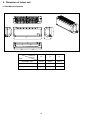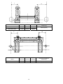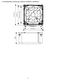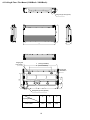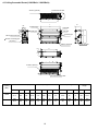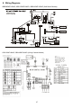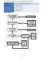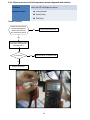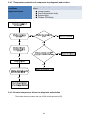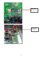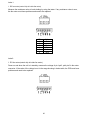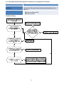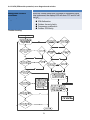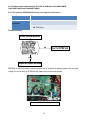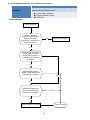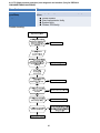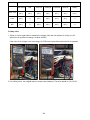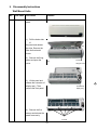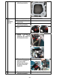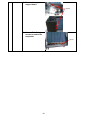
1
WB, CB, RB, UB, FB SERIES INDOOR UNITS FOR MULTI SPLIT SYSTEM AIR CONDITIONER AND HEAT PUMP. SERVICE MANUAL. Multi Zone AND MATCHED OUTDOOR UNITS, BOTH PRE 2014 (PRE 50130070 SERIALS) AND 2014 AND NEWER (50130070 and NEWER SERIALS) Parker Davis HVAC International, Inc. 2260 NW 102nd Place, Doral, FL 33172 Ph: (305) 513‐4488 info@pd‐hvac.com Model Numbers: WB009GMFI16MLD WB012GMFI16MLD Outdoor unit Service Manual CB012GMFI16MLD ODMI‐C1‐1310/ODMI‐C2‐1310 RB012GLFI16MLD UB012GMFI16MLD FB012GMFI16MLD WB012GMFI16MLD CB018GMFI16MLD RB018GMFI16MLD UB018GMFI16MLD Table of Contents 1. Precaution 2. Product Specifications 3. Product Description And Label 4. Dimension of indoor unit 5. Display Function 6. Operation Characteristics 7. Electronic function 8. Wiring Diagrams And Electrical Trouble Shooting 9. Disassembly instructions 10. Exploded view WARNING Installation MUST conform with local building codes or, in the absence of local codes, with the National Electrical Code NFPA70/ANSI C1-1993 or current edition and Canadian Electrical Code Part1 CSA C.22.1. The information contained in the manual is intended for use by a qualified service technician familiar with safety procedures and equipped with the proper tools and test instruments Installation or repairs made by unqualified persons can result in hazards to you and others. Failure to carefully read and follow all instructions in this manual can result in equipment malfunction, property damage, personal injury and/or death. CONTENTS 1. 1. Precaution ....................................................................................................................................................2 1.1 Safety Precaution............................................................................................................................................2 1.2 Warning ..........................................................................................................................................................2 2. Product Specifications ......................................................................................................................................5 3. Features ............................................................................................................................................................6 4. Dimension of indoor unit ............................................................................................................................... 15 Dimension .......................................................................................................................................................... 15 mm(in) ............................................................................................................................................................... 15 5. Service Space (unit: mm) ............................................................................................................................... 21 6. Operation Characteristics .............................................................................................................................. 23 7. Electronic Function ........................................................................................................................................ 23 7.1 Abbreviation ................................................................................................................................................ 23 7.2Main Protection ............................................................................................................................................ 23 7.3 Operation Modes and Functions ................................................................................................................. 23 8. Wiring Diagrams ............................................................................................................................................ 27 9. Troubleshooting ............................................................................................................................................ 30 9.1 Display Board ............................................................................................................................................... 30 Wall Mount Models ....................................................................................................................................... 30 9.2Indoor Unit Error Display .............................................................................................................................. 32 Wall Mount Units .............................................................................................................................................. 32 9.3 Outdoor Unit Error Display .......................................................................................................................... 34 9.4 Diagnosis and Solution ................................................................................................................................ 36 9.5 Trouble Criterion Of Main Parts. ............................................................................................................... 100 10. Disassembly Instructions ......................................................................................................................... 111 or injury. Be cautious when unpacking and installing the product. Sharp edges could cause injury, be especially careful of the case edges and the fins on the condenser and evaporator. 1. 1. Precaution 1.1 Safety Precaution For installation, always contact the dealer or an authorized service center. Do not install the product on weak or defective structures or stands. Be sure the installation area does not deteriorate with age. If the base collapses, the air conditioner could fall with it, causing property damage, product failure, and personal injury. To prevent injury to the user or other people and property damage, the following instructions must be observed carefully. Incorrect operation due to ignoring instructions will cause harm or damage. Before servicing the unit, be sure to read this service manual entirely. 1.2 Warning Do not let the air conditioner run for a long time when the humidity is very high and a door or a window is left open. Take care to ensure that power cable could not be pulled out or damaged during operation. There is risk of fire or electric shock. Installation Do not use a defective or underrated circuit breaker. Use this appliance on a dedicated circuit. There is risk of fire or electric shock. For electrical work, contact the dealer, seller, a qualified electrician, or an authorized service center. Do not disassemble or repair the product, there is risk of fire or electric shock. Do not place anything on the power cable. There is risk of fire or electric shock. Do not plug or unplug the power supply during operation. There is risk of fire or electric shock. Always ground the product. There is risk of fire or electric shock. Do not touch the product with wet hands during operation. Do not place a heater or other appliance near the power cable. There is risk of fire and electric shock. Install the panel and the cover of control box securely. There is risk of fire of electric shock. Always install a dedicated circuit and properly rated breaker. Improper wiring or installation may cause electric shock. Do not allow water to run into electrical parts. It may cause fire, failure of the product, or electric shock. Use the correctly rated breaker or fuse. There is risk of fire or electric shock. Do not modify or extend the power cable. There is risk of fire or electric shock. Do not store or use flammable gas or combustibles near the product. There is risk of fire or failure of product. Do not install, remove or reinstall the unit by yourself (End User). There is risk of fire, electric shock, explosion, Do not use the product in a tightly closed space for a long time. Oxygen deficiency could occur. 2 CAUTION When flammable gas leaks, turn off the gas and open a window for ventilation before turning the product on. If strange sounds or smoke comes from product, turn the breaker off or disconnect the power supply cable. There is risk of electric shock or fire. Always check several times for refrigerant leakage after installation or repairing the product. Low refrigerant levels may cause failure of product. Install the drain hose to ensure that water is drained away properly. A bad connection may cause water leakage. Stop operation and disconnect the power during storm or hurricane. If possible, further secure the product before the hurricane arrives. There is risk of property damage, failure of product, or electric shock. Keep perfect level when installing the product. To avoid vibration of water leakage. Do not install the product where the noise or hot air from the outdoor unit could disturb the neighbors. It may cause disturbance for your neighbors. Do not open the inlet grill of the product during operation. (Do not touch the electrostatic filter, if the unit is so equipped.) There is risk of physical injury, electric shock, or product failure. Use two or more people to lift and transport the product. Do not install the product where it will be exposed to sea wind (salt spray) directly. It may cause corrosion on the product. Corrosion, particularly on the condenser and evaporator fins, could cause product malfunction or inefficient operation. If the indoor section gets wet, contact an authorized service center. There is risk of fire or electric shock. Be cautious that water should not enter the product. There is risk of fire, electric shock, or product damage. Operational Ventilate the product from time to time when operating it together with a nearby stove etc. There is risk of fire or electric shock. Do not expose the skin directly to cool air for long time. (Do not sit in the path of the air draft). Do not use the product for special purposes, such as preserving foods, works of art etc. It is a consumer air conditioner, not a precision refrigeration system. There is risk of damage or loss of property. Turn the main power off when cleaning or maintaining the product. There is risk of electric shock. When the product will not be used for a long time, disconnect the power supply by turning off the breaker. There is risk of product damage or failure, or unintended operation. Do not block the inlet or outlet of air flow. Use a soft cloth to clean. Do not use harsh detergents, solvents, etc. There is risk of fire, electric shock, or damage to the plastic parts of the product. Take care to ensure that nobody could step on or fall onto the outdoor unit. This could result in personal injury and product damage. Do not touch the metal parts of the product when removing the air filter. They are very sharp. 3 Be careful and avoid personal injury. Do not step on or put anything on the product. (outdoor unit) Always insert the filter securely. Clean the filter every two weeks or more often if necessary. A dirty filter reduces the efficiency of the air conditioner and could cause product malfunction or damage. Replace the all batteries in the remote control with new ones of the same type. Do not mix old and new batteries or different types of batteries. There is risk of fire or explosion. Do not recharge or disassemble the batteries. Do not dispose of batteries in a fire. They may burn of explode. Do not insert hands or other objects through air inlet or outlet while the product is operating. Do not drink the condensate water drained from the product. Use a firm stool or ladder when cleaning or maintaining the product. If the liquid from the batteries gets onto your skin or clothes, wash it well with clean water. Do not use the remote if the batteries have leaked. 4 2. Product Specifications WALL MOUNT Models WB009GMFI16MLD WB012GMFI16MLD WB018GMFI16MLD 230V~ 60Hz, 1Ph 230V~ 60Hz, 1Ph 230V~ 60Hz, 1Ph Model RPG20B RPG20B RPG28H Brand Welling Welling Welling 58.5 Power supply Ph-V-Hz Input W 43 43 RLA A 0.2 0.2 0.3 LRA A 0.23 0.23 0.356 Winding Resistance Ω 381/267 381/267 183.6/206 Capacitor uF 1.2 1.5 1.5 r/min 1150 / 950 / 800 1150/1000/850 1130/1040/940 Indoor air flow (Hi/Med/Lo) m3/h 450/370/320 570/500/420 880/820/730 Indoor noise level (Hi/Med/Lo) dB(A) 35/30/25 37/32/27 42/37/34 Dimension(W*D*H) mm 710x190x250 790x198x265 920x223x292 Dimension(W*D*H) inch 27.95x7.48x9.84 31.1x7.8x10.43 36.22x8.78x11.5 Packing (W*D*H) mm 770x265x318 875x265x335 1015x295x368 Packing (W*D*H) inch 30.31x10.43x12.52 34.45x10.43x13.19 39.96x11.61x14.49 Indoor fan motor Speed(Hi/Med/Lo) Indoor unit Net/Gross weight Kg 8 / 9.5 9 / 11 11.5 / 15 Net/Gross weight Pound 17.64/20.94 19.84/24.25 25.35/33.07 mm(inch) Φ6.35/Φ9.52(1/4"/3/8") Φ6.35/Φ12.7(1/4"/1/2") Φ6.35/Φ12.7(1/4"/1/2") Liquid side/ Gas side 8-Way Ceiling Cassette Models Power supply Ph-V-Hz Model Qty Indoor fan motor Input Capacitor Speed(Hi/Med/Lo) Indoor air flow (Hi/Med/Lo) (No duct) Indoor external static pressure (Hi) Indoor noise level (Hi/Med/Lo) Dimension(W*D*H) (body) Dimension(W*D*H) (body) Packing (W*D*H) (body) Packing (W*D*H) (body) Dimension(W*D*H) (panel) Dimension(W*D*H) (panel) Packing (W*D*H) (panel) Indoor unit Packing (W*D*H) (panel) Net/Gross weight (body) Net/Gross weight (body) Net/Gross weight (panel) Net/Gross weight (panel) Liquid side/ Gas side W uF r/min m3/h Pa dB(A) mm inch mm inch mm inch mm inch Kg Pound Kg Pound Mm (inch) Floor-Ceiling (Flex Mount) Model Power supply Ph-V-Hz Model Qty Indoor fan motor Input Capacitor Speed(Hi/Med/Lo) Indoor air flow (Hi/Med/Lo) (No duct) Indoor external static pressure (Hi) Indoor noise level (Hi/Med/Lo) Dimension(W*D*H) (body) Dimension(W*D*H) (body) Packing (W*D*H) (body) Packing (W*D*H) (body) Indoor unit Net/Gross weight (body) Net/Gross weight (body) Liquid side/ Gas side W uF r/min m3/h Pa dB(A) mm inch mm inch Kg Pound Mm (inch) 5 CB012GMFI16MLD 208-230V~ 60Hz, 1Ph WZDK37-38G 1 37 / 950/840/670/600 620/520/410 / 50/47/43 570x570x260 22.44x22.44x10.24 655x655x290 25.79x25.79x11.42 647x647x50 25.47x25.47x1.97 715x715x123 28.15x28.15x4.84 16/19 35.27/41.89 2.5/4.5 5.51/9.92 Φ6.35/Φ12.7 (1/4"/1/2") CB018GMFI16MFI 208-230V~ 60Hz, 1Ph WZDK37-38G 1 37 / 950/840/670/600 620/520/410 / 50/47/43 570x570x260 22.44x22.44x10.24 655x655x290 25.79x25.79x11.42 647x647x50 25.47x25.47x1.97 715x715x123 28.15x28.15x4.84 18/21 39.68/46.3 2.5/4.5 5.51/9.92 Φ6.35/Φ12.7( 1/4"/1/2") UB012GMFI16MLD 208-230V~ 60Hz, 1Ph WZDK55-38GS-W 1 55 / 1000/800/700/600 800/620/500 / 43/36/32 990x660x203 38.98x25.98x7.99 1090x745x297 42.91x29.33x11.69 22/28 48.5/61.73 Φ6.35/Φ12.7 (1/4"/1/2") UB018GMFI16MLD 208-230V~ 60Hz, 1Ph WZDK55-38GS-W 1 55 / 1000/800/700/600 800/620/500 / 44/38/33 990x660x203 38.98x25.98x7.99 1090x745x297 42.91x29.33x11.69 23/28.5 50.71/62.83 Φ6.35/Φ12.7 (1/4"/1/2") Ceiling Concealed (Ducted-Recessed) Models Power supply Ph-V-Hz Model Qty Indoor fan motor Input Capacitor Speed(Hi/Med/Lo) Indoor air flow (Hi/Med/Lo) (No duct) Indoor external static pressure (Hi) Indoor noise level (Hi/Med/Lo) Dimension(W*D*H) (body) Dimension(W*D*H) (body) Packing (W*D*H) (body) Packing (W*D*H) (body) Indoor unit Net/Gross weight (body) Net/Gross weight (body) Liquid side/ Gas side W uF r/min m3/h Pa dB(A) mm inch mm inch Kg Pound Mm (inch) RB012GMFI16MLD 208-230V~ 60Hz, 1Ph YSK27-4G 1 71/48.8/36.7 2UF/450V 1255/1005/850 630/550/460 40 40/36/33 700x635x210 27.56x25x8.27 915x655x290 36.02x25.79x11.42 20/25 44.09/55.12 Φ6.35/Φ12.7 (1/4"/1/2") Floor Console Model Power supply Ph-V-Hz Model Qty Indoor fan motor Input Capacitor Speed(Hi/Med/Lo) Indoor air flow (Hi/Med/Lo) (No duct) Indoor external static pressure (Hi) Indoor noise level (Hi/Med/Lo) Dimension(W*D*H) (body) Dimension(W*D*H) (body) Packing (W*D*H) (body) Packing (W*D*H) (body) Indoor unit Net/Gross weight (body) Net/Gross weight (body) W uF r/min m3/h Pa dB(A) mm inch mm inch Kg Pound Mm (inch) Liquid side/ Gas side RB018GMFI16MLD 208-230V~ 60Hz, 1Ph YSK68-4B 1 90/56/43 3.5UF/450V 1010/790/690 800/640/530 70 41/35/33 920x635x210 36.22x25x8.27 1135x655x290 44.68x25.79x11.42 22.5/27.5 50.71/63.93 Φ6.35/Φ12.7 (1/4"/1/2") FB012GMFI16MLD 208-230V~ 60Hz, 1Ph RD-280-20-8A 1 20 / 680/560/460/420/350 450/390/350 / 38/33/30 700x600x210 27.56x23.62x8.27 810x710x305 31.89x27.95x12.01 15/20 33.07/44.09 Φ6.35/Φ12.7 (1/4"/1/2") 3. Features 3.1 New Eight-Way Cassette Type (Compact) ⑴ New panel 360°surround (8-Way Discharge) air outlet design, provides a comfortable and even air distribution. 6 ⑵ Compact design The body size is 570×260×570mm, (22.5 x 22.5 x 10.25H Inches) which just smaller than the standard ceiling tile grid size, for very easy installation, to blend in any decoration. The panel size is 647×50×647mm. (25.5 x 25.5 x 2H Inches) The attachment hooks are located at the four corners of the body, which saves installation space. ⑶ Electric control box built-in The Electronic controller system box is built inside the indoor unit. It’s location is very convenient for installation and maintenance. To access the controller, user only needs to open the air return grille. ⑷ Fresh air intake function: Fresh air intake allows improved indoor air quality and comfort. 7 Fresh Air Dimension: Φ75mm (3") ⑸ Air passage function Reserved external duct connection knockout plates are available for remote air outlets from the sides of indoor unit, to connect air ducts at the sides to feed air to one or two nearby areas. 3.2 Ceiling & Floor type ⑴ Two-way (Flex Mounting) Installation The rounded design of the ceiling and floor type air conditioner allows either ceiling or floor-level installation. Ceiling installation saves room space while floor installation allows each reach. 8 ⑵ ⑶ Compact Design Compact design that makes the unit suitable for any interior space. 3D Airflow Vertical air flow and horizontal airflow directions can be adjusted by remote controller. Combining two airflow directions help spread the air comfortably throughout even large rooms. With these functions, the whole room can be evenly air-conditioned for both floor-level and ceiling installed applications. Optional drainage pipe connection Both right side and left side drainage holes are available to avoid the space limitation for drainage pipe installation for added convenience. ⑷ Convenient operation and easy maintenance Remote controllers included as standard, wired controller optional. The filter rack without screwed fixing, allowing filters to be removed and serviced easily. 9 ⑸ Easy installation, saves time The pipes can be connected from bottom, back and right side, making the installation easy. The wiring work can be finished before the installation. 3.3 A5 Duct ⑴ Installation accessories: (Optional) Front Discharge Duct Connector, Canvas Air Passage, Filter, Panel, for easy installation Duct Connector Canvas Air Passage Filter Access Panel ⑵ Easy Installation: Two air inlet styles (Bottom side or Rear Return, Field Convertible) Air inlet from rear is standard for all capacity; air inlet from bottom is available by simple conversion The size of air inlet frame from rear and bottom is same, it’s very easy to move the cover from bottom to rear side, or from rear to the bottom, in order to match the installation requirements. Air intake from bottom (Field Converted) Air intake from rear (Standard) 10 ⑶ Fresh air intake function For utmost comfort, a fresh air intake duct connection is available. ⑷ Easy maintenance Easy to clean the filter (Filter is optional, standard product is shipped without filter) It is easy to slide out the filter from the indoor unit for cleaning, whether the filter is installed on the rear or the bottom side. Easy replacement access for the motor or centrifugal fans Ventilated panel can be removed easily. Blower housing's are made in top and bottom halves, and removing the bottom halve allows taking out motor with centrifugal fan assembly easily. Only requirement is the removal of two bolts to finish the job.. Motor Blower Housing Ventilated Panel ⑸ Reserved remote on-off and central control ports Reserved remote on-off ports and central control ports, allow connecting cables of an on-off controller or a central controller to provide remote on-off control function or group control function. 11 Remote on‐off ports Central control ports ⑹ Built-in drain pump (Optional): Built-in drain pump can lift the water up to 750 mm (30 Inches). This provides the conveniency to install drainage piping even under most difficult space limitations. 750mm upmost ⑺ Built-in display Thermostat The standard indoor unit is controlled by wired electronic controller. There is also a display board with a receiver inside the E-box. This part can be located elsewhere up to 10m (30 Feet) for remote controller access. The wired controller and the display board can display the error codes or production codes when the chips detect any failure. 12 Wired Controller (Standard) Remote Controller (Optional) Display 3.4 Console ⑴ Modern and elegant appearance The simple and stylish designs blend in your living space. ⑵ Two air-outlets in Cooling mode Quick Cooling To maintain room temp Air outlet from top and bottom to make quick cooling ------When the system is newly switched on, or room temperature remains high, cold air will be blown out from top and bottom air outlets to cool down the room quickly. Air outlet from top to maintain room temp. ----When the room has been cooled down, or the A/C has been working over 1 hour, cold air discharged only from the top outlet will help maintain constant room temp. 13 Heating mode Anti-cold air draft (Warm Start) ------When the system if first turned on, temperature of indoor heat exchanger is very low. Therefore, in order to prevent cold air draft directly blowing onto the people nearby, only the upper louver is opened in a high position, the lower louver will remain closed. ⑶ Four air inlets ⑷ Low noise DC indoor fan motor, with five speeds. Low noise and great energy savings. Advanced centrifugal fan technology for high airflow and reduced noise to a level as low as 28dB. ⑸ ⑹ Golden fin is optional. Active carbon filter is standard. 14 4. Dimension of indoor unit 4.1 Wall Mounted Systems H D W Dimension mm(in) W H D WB009GMFI16MLD 710(28) 250(9.8) 190(7.5) WB012GMFI16MLD 790(31.1) 265(10.4) 198(7.8) WB018GMFI16MLD 920(36.2) 292(11.5) 223(8.8) Model 15 L R H Model R(mm(in)) L(mm(in)) H(mm(in)) WB009GMFI16MLD 111.5(4.4) 100(3.9) 45(1.8) WB012GMFI16MLD 151(5.9) 100(3.9) 45(1.8) Dimension of installation hole(mm(in)) Φ65mm(2.56in) R L H Model R(mm(in)) L(mm(in)) H(mm(in)) Dimension of installation hole(mm(in)) WB018GMFI16MLD 186.5(7.3) 150(5.9) 45(1.8) φ65(2.56in) 16 545(Hook-location) 570(Body) 647(Panel) 4.1 New Eight-Way Cassette type (compact) (12000Btu/h / 18000Btu/h) : 545(Hook-location) 570(Body) 260 647(Panel) 17 100 4.2 Ceiling & Floor / Flex Mount (12000Btu/h / 18000Btu/h): 100 660 Refrigerant pipe hole (optional) 203 A Hanging arm £ f̈or ceiling) C (Ceiling Installation) B (Floor Installation) 100 180 506 200 Hanging arm £ f̈or Floor£ © 100 Refrigerant pipe hole (optional) Dimension A B C 990 (39") 505 (20") 907 (23") Capacity(Btu/h) 12000-18000 18 4.3 Ceiling Concealed Ducted (12000Btu/h / 18000Btu/h) air inlet from rear side J Air filter ( optional ) I L B A Liquid side Test mouth & Test cover 25 Drain pipe C Gas side 25 Drain pipe M W2 W1 4-install hanger D H2 H1 25 Drain connecting pipe ( for pump ) Fresh air intake E F H G Electric control box K Air filter ( optional ) air inlet from bottom side Outline dimension(mm) Capacity (Btu) Air outlet opening size Size of install hanger Air return opening size A B C D E F G H I J K L M 12000 700 27.5" 210 8.3" 635 25" 570 22.5" 65 2.5" 493 19.5" 35 1.4" 119 47" 595 23.5" 200 8" 80 3" 740 29" 350 13.8" 18000 920 36.2" 210 8.3" 635 25" 570 22.5" 65 2.5" 713 28" 35 1.4" 119 47" 815 32" 200 8" 80 8" 960 38" 350 13.8" 19 4.4 Floor Console (12000Btu/h /18000Btu/h) 20 5. Service Space (unit: mm) A≧280 5.1 Eight-Way Cassette (compact) Ceiling >230 Outlet Outlet Inlet Ground 5.2 Ceiling & Floor / Flex Mount C ¡3 Ý5mm ¡3 Ý5mm ¡Ý 3 5mm 21 ¡Ý 1 000mm 5.3 Ceiling Concealed Ducted / Recessed 5.4 Floor Console ≥100mm ≥100mm ≥100mm ≥1000mm 22 6. Operation Characteristics Temperature Mode Cooling operation Heating operation Drying operation ≥62℉ ≤88℉ ≥62℉ Room temperature Outdoor temperature 32℉~122℉ (5℉~122℉ :For the models with low temperature cooling system) ----When Indoor Fan Speed stays too low or too high for certain time, the unit will stop and the LED will display the failure code. 5℉~76℉ 32℉~122℉ 7.2.3 Indoor fan delayed open function CAUTION: ----When the system starts up, the louver will be 1. If air conditioner is used beyond the above active immediately and the indoor fan will start conditions, the certain protections may be 10s later. triggered. ----If the system runs in heating mode, the indoor 2. Room relative humidity should be less than fan will be controlled by anti-cold draft (warm 80%. If the air conditioner operates in excess of Start function. this value, the surface of the air conditioner may 7.3 Operation Modes and Functions attract condensation. In this case, please set the 7.3.1 Fan mode. vertical air louver to its maximum angle (vertically to the floor), and set the fan to high speed. (1) The outdoor fan and compressor stop. (2)Temperature setting function is disabled, and 7. Electronic Function no setting temperature is displayed. 7.1 Abbreviation (3) Indoor fan can be set to high/med/low/auto. T1: Indoor ambient temperature (4) The louver operates as same as in cooling T2: Pipe temperature of indoor heat exchanger mode. T3: Pipe temperature of outdoor heat exchanger (5) Auto fan: The action of auto fan in fan-only mode is the T4: Outdoor ambient temperature same as auto fan in cooling mode with 24℃ Tp: Discharge temperature setting temperature. Ts:Setting temp. 7.2 Main Protections 3.5 High 7.2.1 Three Minutes Delay at restart for 3.0 compressor. 1.5 Medium 1.0 7.2.2 Fan Speed is out of control (For units Low Ts=24℃ using DC motor) 23 7.3.2 Cooling Mode 7.3.3.2 High evaporator coil temp.T2 protection: 7.3.2.1 Indoor fan running rules If T2>63℃, while the indoor unit has no capacity In cooling mode, indoor fan runs all the time and the speed can be selected as high, medium, low 7.3.3.3 Prevent Over-Heating and auto. In heating mode, when the indoor unit has no capacity requirement when the indoor room temperature setting is satisfied, the Indoor fan will run in Lowest Available Speed. (Anti-cold draft / Warm Start function has the priority) Auto fan in cooling mode acts as follows: 7.3.4 Auto-mode 3.5 High 3.0 This mode can be chosen by remote controller Medium 1.5 and the setting temperature can be changed 1.0 between 17~30℃. (64F~86F) Low In auto mode, the system will choose cooling, 7.3.2.4 Evaporator low temperature T2 heating or fan-only mode according to ΔT (ΔT protection. =T1-Ts). When T2<4℃, for 3 minutes, the indoor has no ΔT=T1-Ts capacity demand. Resume at T2>7℃. Running mode Cooling ΔT>1℃ -1<ΔT≤1℃ Fan-only Heating ΔT≤-1℃ 7.3.3 Heating Mode 7.3.3.1 Indoor fan running rules: Indoor fan speed can be set as high, medium, low Indoor fan will run at auto fan of the relevant and auto fan and the anti-cold-draft (Warm Start mode. function has preference. The louver operates same as in relevant mode. Auto fan action in heating mode. If the system switches its mode between heating and cooling, the compressor will stay stopped for T1-Ts-¦ ¤ T 15 minutes and then select the mode according Low to T1-Ts. 2.5 2 If the setting temperature is modified, the system Medium will reselect running function. 1.5 1 High 24 7.3.5 Dehumidifier mode Forced auto mode: 7.3.5.1 Indoor fan speed is set at breeze speed The action of forced auto mode is the same as and cannot be changed. The louver angle is the normal auto mode with 24℃ (75F) setting same as in the cooling mode. temperature. 7.3.5.2 Low room temperature protection: 7.3.6.4 When there’s an indoor unit running in forced cooling, it becomes the master forced In dehumidifier mode, if room temperature is cooling unit. Other indoor units will run at forced lower than 10℃ (50F), the indoor fan will stop cooling mode as well and they will become the and not resume until room temperature exceeds slave forced cooling units. The slave forced 12℃ (54F). cooling units cannot quit forced cooling mode until the master forced cooling unit quits, and 7.3.5.3 Evaporator freeze up protection is active switch to cooling mode with low fan speed and 7.3.6 Forced operation function with 24℃ (75F) setting temperature. 7.3.6.1 Enter forced operation function: For other models:: Press the emergency start button continually, the 7.3.6.5 The slave forced cooling units will not be system will run as per the below sequence: controlled by other signals except timer off signal. 7.3.6.6 If AC is running in sleep mode and receives forced operation signal, it will quit the sleep mode. When the system is off, pressing the emergency 7.3.7 Timer function button will bring the system into forced auto 7.3.7.1 Timing range is 24 hours. mode. In this more, pressing the button once more, will bring the system into forced cooling 7.3.7.2 Timer on. The machine will turn on mode. In forced cooling mode, pressing the automatically when reaching the set ON time. button will turn off the machine. 7.3.7.3 Timer off. The machine will turn off 7.3.6.2 In forced operation mode, all general automatically when reaching the set OFF time. protections and remote control are available. 7.3.7.4 Timer on/off. The machine will turn on 7.3.6.3 Operation rules: automatically when reaching the set “on” time, Forced cooling mode: and then turn off automatically when reaching the set “off” time. The indoor fan runs as breeze. After running for 30 minutes, AC will switch to auto mode with 24 7.3.7.5 Timer off/on. The machine will turn off ℃ (75F) setting temperature. automatically when reaching the set “off” time, 25 and then turn on automatically when reaching the not stop until reaching the setting time in sleep setting “on” time. mode. 7.3.7.6 The timer function will not change the 7.3.9 Auto-Restart function system's currently set operation mode. The indoor unit is equipped with auto-restart 7.3.7.7 The setting time is relative time. function, which is carried out through an autorestart module memory. In case of a sudden 7.3.8 Sleep function mode power failure, the module memorizes the setting 7.3.8.1 The sleep function is available in cooling, conditions before the power failure. The unit will heating or auto modes. resume the previous operation settings (Excluding Swing function) automatically within 3 7.3.8.2. Operation process in sleep mode is as minutes after the power returns. follows: If the memorization condition is forced cooling In Cooling Mode, the setting temperature rises by mode, the unit will run in cooling mode for 30 1℃ (2F) steps (while lower than 30℃, 86F) once minutes and turn to auto mode with 24℃ (75F) every one hour. 2 hours later the setting setting temp. temperature stops rising and the indoor fan is 7.3.10 Drain pump control (For Duct & runs at auto speed. Cassette units) In Heating Mode, the setting temperature A water-level switch controls the action of the drain pump. decreases by 1℃ (2F) (while higher than 17℃, 63F) once every one hour. 2 hours later the Main action under different condition: ( every 5 seconds the system will check the water level) setting temperature stops rising and indoor fan is runs at auto speed. (Anti-cold draft / Warm Start 1. When the A/C operates in cooling (including auto cooling), dehumidifying and forced cooling modes, the pump will start running immediately and continuously, till cooling stops. function has the priority). 7.3.8.3 Operation time in sleep mode is 7 hours. After 7 hours the systems turns off. 2. In case the water level increases beyond the controlled point, LED will flash an alarm and the drain pump will start while continuously checking the water level. If the water level comes down and LED alarm condition is removed (drain pump has a 1 minute OFF delay) than it will operate based on the last mode. Otherwise the entire system stop operating (including the pump) and LED remain with the alarm after 3 minutes. 7.3.8.4 Shutdown or changing the mode or speed setting will cancel the economic operation. 7.3.8.5 When user uses timer off function in sleep mode (or sleep function in timer off mode), if the timing was less than 7 hours, sleep function will be cancelled when reaching the setting time. If the timing was more than 7 hours, the system will 26 8. Wiring Diagrams WB009GMFI16MLD, WB012GMFI16MLD, WB018GMFI16MLD (Wall Mount Models) CB012GMFI16MLD, CB018GMFI16MLD (Ceiling Cassette Models) 27 UB012GMFI16MLD, UB018GMFI16MLD (Floor0Ceiling, Flex Mount Models). RB012GMFI16MLD, RB018GMFI16MLD (Ceiling Concealed, Ducted Recessed Models). 28 FB012GMFI16MLD (Floor Console Models). 29 Troubleshooting 9.1 Display Board 9.1.1 Icon explanation on indoor display board (WB Series Wall Mount Models) AUTO indication lamp Lights up during the auto operation. TIMER indication lamp Lights up during Timer operation. DEFROST indication Lights up when the air conditioner starts defrosting lamp (For cooling & automatically or when the warm air control (Warm Start) heating models only): Ion indication feature is activate in heating operation. Illuminate when Ionizer/Plasma function is activated DIGITAL DISPLAY: Displays the current setting temperature and malfunction/protection code when the air conditioner is in operation. Frequency display: This display is separated into five zones. The zones illuminate based on the compressor current frequency. For example, higher frequency will illuminate more zones. 9.1.2 Icon explanation on indoor display board (CB Series Compact cassette) 30 9.1.3 Icon explanation on indoor display board (UB Series Ceiling & floor) 9.1.4 Icon explanation on indoor display board (RB Series Ceiling Recessed Ducted) PRE-DEF indicator(cooling and heating type) or fan only indicator(cooling only type) Timer indicator Alarm indicator Operation lamp Infrared signal receiver Display digital tube Temporary button MANUAL OPERATION TIMER DEF./FAN ALARM 9.1.5 Icon explanation on indoor display board (FB Series Console) 31 9.2Indoor Unit Error Display WB Series Wall Mount Units Display Failure E0 Indoor EEPROM malfunction E1 Indoor/ outdoor units communication error E2 Zero-crossing signal error E3 Indoor fan speed has been out of control E5 Open circuit or short circuit of outdoor temperature sensor or outdoor EEPROM malfunction E6 Open circuit or short circuit of T1 or T2 temperature sensor P0 IPM module protection or IGBT over-strong current protection P1 Voltage protection P2 Temperature protection of compressor top P3 Outdoor temperature is lower than -15°C (optional function) P4 Inverter compressor drive protection P5 Mode conflict Note P3: If the outdoor temperature <= -15 °C for 1 hour, then the machine stops running, the indoor display shows the error code "P3“. The unit can still receive remote control signals. If the outdoor >= -12 °C for 10 minutes, the compressor stops running more than one hour, Or the outdoor temperature>= 5 ℃ for 10 minutes, then AC will recover to the last mode and fan speed. E4 : Reserved function. 32 FB Series Floor Console Operation Timer De-frost ★ X X Open or short circuit of T1 temperature sensor X X ★ Open or short circuit of T2 temperature sensor X ★ X Indoor / outdoor units communication error ★ ★ X Indoor EEPROM malfunction X ★ Outdoor fan speed has been out of control ★ X ★ IPM module protection ★ ★ ★ Open or short circuit of T3 or T4 temperature sensor or Outdoor unit EEPROM parameter error ★ X Temperature protection of compressor top ★ ◎ X Inverter compressor drive protection ★ X Mode conflict ★ ★ Indoor fan speed has been out of control Failure ★ flash at 5/sec, light ON, X extinguished, ◎flash at 0.5/sec For RB Concealed-Duct, UB Floor-Ceiling, CB Ceiling Cassette: Operation Timer De-frost Alarm Failure ★ X X X Open or short circuit of T1 temperature sensor E0 X X ★ X Open or short circuit of T2 temperature sensor E1 X ★ X X Indoor / outdoor units communication error E2 X X X ★ Full-water malfunction E3 ★ ★ X X Indoor EEPROM malfunction E4 ★ X X IPM module protection E5 ★ X X Open or short circuit of T3 or T4 temperature sensor or outdoor EEPROM malfunction E6 ★ ★ X Outdoor fan has been out of control E7 ★ X Indoor fan speed has been out of control F5 ★ X Voltage protection P0 ★ X X Temperature protection of compressor top. P1 ★ ★ ★ X Outdoor unit over-current protection P2 ★ ◎ X X Inverter compressor drive protection P4 ★ X Mode conflict P5 ★ flash at 2.5/sec light ON, X extinguished, , ◎flash at 0.5/sec Note: Digital display is only available for duct type. 33 Display 9.3 Outdoor Unit Error Display For YN018GMFI16M2D, YN027GMFI16M3D, YN030GNFI16M3D, YN036GMFI16M4D (2014 and Newer) Display LED STATUS IDU Error (Wall) IDU Error (Others) E0 Outdoor EEPROM malfunction E5 E6 E2 Indoor / outdoor units communication error E1 E2 E3 Communication malfunction between IPM board and outdoor main board —— —— E4 Open or short circuit of outdoor temperature sensor(T3、T4、TP、T2B) E5 E6 E5 Voltage protection P1 P0 E6 PFC module protection(Only for M4OC-36HRFN1-M) —— —— E8 Outdoor fan speed has been out of control(Only for DC fan motor models) E7 E7 F1 No A Indoor unit coil outlet temp. sensor or connector of sensor is defective —— —— F2 No B Indoor unit coil outlet temp. sensor or connector of sensor is defective —— —— F3 No C Indoor unit coil outlet temp. sensor or connector of sensor is defective —— —— F4 No D Indoor unit coil outlet temp. sensor or connector of sensor is defective —— —— P0 Temperature protection of compressor top (Only for M3OD-27HRDN1-M) P2 P3(P1) P1 High pressure protection (Only for M4OC-36HRFN1-M) —— —— P2 Low pressure protection(Only for M4OC-36HRFN1-M) —— —— P3 Current protection of compressor —— ——(P2) P4 Temperature protection of compressor discharge —— —— P5 High temperature protection of condenser —— —— P6 IPM module protection P0 E5 34 For Older (PRE 2014) Multi Split System Outdoor Units, YN018GMFI16M2D, YN027GMFI16M3D and YN036GMFI16M4D Display digital tube LED STATUS IDU Error (Wall) IDU Error (Others) E5 E6 E0 Outdoor EEPROM malfunction E1 No A Indoor unit coil outlet temp. sensor or connector of sensor is defective —— —— E2 No B Indoor unit coil outlet temp. sensor or connector of sensor is defective —— —— E3 No C Indoor unit coil outlet temp. sensor or connector of sensor is defective —— —— E6 No D Indoor unit coil outlet temp. sensor or connector of sensor is defective —— —— E4 Open or short circuit of outdoor temperature sensor(T4) E5 E6 E5 Voltage protection P1 P0 E7 Communication malfunction between IPM board and outdoor main board —— —— P0 Temperature protection of compressor discharge (Temperature protection of compressor top(only for M2OC-18HRDN1-M&M3OC-27HRDN1-M)) P2 P3(P1) P1 High pressure protection (Only for M4OC-36HRDN1-M) —— —— P2 Low pressure protection(Only forM4OC-36HRDN1-M) —— —— P3 Current protection of compressor —— ——(P2) P4 IPM module protection P0 E5 P6 High temperature protection of condenser —— —— P7 Inverter compressor drive protection P4 P4 PF PFC module protection(Only for M4OC-36HRDN1-M) —— —— 35 9.4 Diagnosis and Solution 9.4.1 Indoor unit trouble shooting 9.4.1.1 Indoor EEPROM malfunction diagnosis and solution. Malfunction decision conditions Supposed causes PCB main chip does not receive feedback from EEPROM chip ● Installation mistake ● PCB faulty Trouble shooting: Shut off the power supply and turn it on 1 minute later. Is it still displaying the error code? Yes If the EEPROM chip is welded on PCB, replace the PCB directly. Otherwise, check whether the EEPROM chip plugged in PCB well? No Insert the EEPROM well Yes Replace the indoor PCB. EEPROM: a read-only memory whose contents can be erased and reprogrammed using a pulsed voltage. For the location of EEPROM chip, please refer to the below photos. 9.4.1.2 Indoor / outdoor unit communication error diagnosis and solution. Malfunction decision conditions Supposed causes Indoor unit does not receive the feedback from outdoor unit for 120 seconds. ● Wiring mistake ● Indoor or outdoor PCB faulty 36 Trouble shooting: Indoor / outdoor units communication error Start: Power off , then Power on the A/C by the Breaker. (reconnect the power wire). Is it still displaying the error code? Yes Check wiring on the outdoor and indoor terminal follow the wiring diagram. Is all connecting correctly? No Reconnect the wiring No Reconnect the wiring Yes Turn on all indoor unit by remote controller. Is all indoor unit display No Measure Vs, is it moving alternately between positive value and negative value? (Vs is the voltage between S and L2). Refer PIC 1 A: Is all the wiring between No terminal and Indoor PCB connect ok? Yes Yes Yes Yes Turn off the all indoor units. Is IPM power LED or operating LED lamp On? Refer PIC2 No Change the Indoor PCB change IPM Power on by remote controller, IIs it still Yes displaying the error code after 3 minutes? Is main board“ ” lamp on? Refer PIC 3. No Is the reactor connecting well? No Reconnect the wiring No Yes Yes Change Outdoor Main PCB Is indoor units number correct? Check on the outdoor check point . (2 for dual zone, 3 for tri zone, 4 for qua zone). Refer PIC 4. No first time No second time Trouble is solved A Change outdoor unit PCB assembly(include wiring) totally 37 No Pic 1:Use a multimeter to test the DC voltage between L2 port and S port of outdoor unit. The red pin of multimeter connects with L2 port while the black pin is for S port. When AC is running normally, the voltage will move alternately between positive value and negative value. Pic 2: :IPM (for dual/trio/quad-zone) Power (some modles) Self‐Check OK Operating 38 PIC3 :Main board LED when power on and unit standby. PIC 4: Check point button, press 1 time for check how many indoor units are connected (For 2014 and Newer OUTDOOR Units) Check point button, press 18 times for check how many indoor units are connected (for Pre 2014 OUTDOOR Units) 39 9.4.1.3 Indoor fan speed has been out of control diagnosis and solution. Malfunction decision conditions Supposed causes When indoor fan speed stays too low (300RPM) for certain time, the unit will stop and the LED will display the failure. ● Wiring mistake ● Fan ass’y faulty ● Fan motor faulty ● PCB faulty Trouble shooting: 40 Index 1: 1.Indoor AC fan motor Measure the resistance value of each winding by using the tester. For the definite value of the resistance, refer to 9.5 Trouble Criterion Of Main Parts 2. Indoor DC fan motor(control chip is inside fan motor) Measure the resistance value of each winding by using the tester. If any resistance value is zero, the fan motor must have problems and need to be replaced. For console: 5 4 6 3 1 2 NO. Color 1 Red 2 --- 3 White 4 Blue 5 Yellow 6 Black 41 For other models: NO. 1 2 3 4 5 6 Color Red --Black White Yellow Blue Index2: 1: Indoor AC fan motor Power on and set the unit running in fan mode at high fan speed. After running for 15 seconds, measure the voltage of pin1 and pin2. If the value of the voltage is less than 100V(208~240V power supply)or 50V(115V power supply), the PCB must have problems and need to be replaced. 2. Indoor DC fan motor(control chip is inside fan motor) Power on and when the unit is in standby, measure the voltage of pin1-pin3, pin4-pin3 in fan motor connector. If the value of the voltage is not in the range showing in below table, the PCB must have problems and need to be replaced. 42 For other models: For console: 5 4 6 3 1 2 DC motor voltage input and output For light commercial(except console): NO. Color Signal Voltage 1 Red Vs/Vm 192V~380V 2 --- --- --- 3 Black GND 0V 4 White Vcc 13.5-16.5V 5 Yellow Vsp 0~6.5V 6 Blue FG 15V For console: NO. Color Signal Voltage 1 Red VDC 310V 2 --- --- --- 3 White Vcc 15V 4 Blue FG 15V 5 Yellow Vsp 0-7.5V 6 Black GND 0V 43 9.4.1.4 Open or short circuit of temperature sensor diagnosis and solution. Malfunction decision conditions If the sampling voltage is lower than 0.06V or higher than 4.94V, the LED will display the failure. Supposed causes ● Wiring mistake ● Sensor faulty ● PCB faulty Trouble shooting: Check the connections between temperature sensor and PCB. Are the connections good? No Correct the connections. Yes Check the resistance value of the sensor via Appendix 1 and Appendix 2 Is it normal? Yes Replace indoor or outdoor PCB. No Replace the sensor 44 9.4.1.5 IPM module or IGBT over-strong current protection diagnosis and solution. Malfunction decision conditions Supposed causes When the voltage signal that IPM send to compressor drive chip is abnormal, the display LED will show “P6” and AC will turn off. ● Wiring mistake ● IPM malfunction ● Outdoor fan ass’y faulty ● Compressor malfunction ● Outdoor PCB faulty 45 Trouble shooting: 46 9.4.1.6 High voltage or Low voltage protection diagnosis and solution. 47 9.4.1.7 Temperature protection of compressor top diagnosis and solution. Malfunction decision conditions Supposed causes If the sampling voltage is not 5V, the LED will display the failure. ● Wiring mistake ● Over load protector faulty ● System block ● Outdoor PCB faulty 9.4.1.8 Inverter compressor drive error diagnosis and solution The trouble shooting is same with one of IPM module protection (P0). 48 9.4.1.9 Full-Water malfunction diagnosis and solution (For Cassette / Concealed Duct) Malfunction decision conditions Supposed causes If the sampling voltage is not 5V, the LED will display the failure. ● Wiring mistake ● Water-level switch faulty ● Water pump faulty ● Indoor PCB faulty 49 9.4.1.10 Mode conflict. Error Code P5 Malfunction decision conditions The indoor units cannot work cooling mode and heating at same time. Heating mode has a priority. Unit action ● When Indoor unit A working in cooling mode or fan mode, and indoor unit B is set to heating mode, then A will change to off and B will work in heating mode. ● When Indoor unit A working in heating mode, and indoor unit B is set to cooling mode or fan mode, then B will change to stand by and A will have no change. Cooling mode Heating Mode Fan Off Cooling mode No Yes No No Heating Mode Yes No Yes No Fan No Yes No No Off No No No No No: No mode conflict; Yes: Mode conflict 50 9.4.2 Outdoor unit trouble shooting. For Newer (2014 and Newer) YN018GMFI16M2D, YN027GMFI16M3D, YN030GNFI16M3D, YN036GMFI16M4D Models. 9.4.2.1 E0 (Outdoor EEPROM malfunction) error diagnosis and solution Error Code E0 Malfunction decision conditions Supposed causes PCB main chip does not receive feedback from EEPROM chip ● Installation mistake ● PCB faulty Trouble shooting: EEPROM: a read-only memory whose contents can be erased and reprogrammed using a pulsed voltage. For the location of EEPROM chip, please refer to the below photos. Outdoor PCB(YN030GMFI16M3D) 51 9.4.2.2 E2 (Indoor / outdoor unit communication error) error diagnosis and solution. Error Code E2 Malfunction decision conditions Supposed causes Indoor unit does not receive the feedback from outdoor unit for 120 seconds or outdoor unit does not receive the feedback from any one indoor unit for 180 seconds. ● Wiring mistake ● Indoor or outdoor PCB faulty Trouble shooting: 52 Pic 1:Use a multimeter to test the DC voltage between L2 port and S port of outdoor unit. The red pin of multimeter connects with L2 port while the black pin is for S port. When AC is running normally, the voltage will move alternately between positive value and negative value. Pic 2: :IPM (For dual/trio-zone) Operating Self‐Check 53 Pic 2: :IPM (For quad-zone) Power, Self‐Check Operating PIC3 :Main board LED when power on and unit standby. PIC 4: Check point button, press 1 time for check how many indoor units are connected. 54 9.4.2.3 E3 (Communication malfunction between IPM board and outdoor main board) error diagnosis and . Error Code E3 Malfunction decision conditions Supposed causes PCB main chip does not receive feedback from IPM module for 60 seconds. ● Wiring mistake ● PCB faulty Trouble shooting: 55 Remark: Use a multimeter to test the DC voltage between black pin and white pin of signal wire The normal value should be around 5V. Use a multimeter to test the DC voltage between black pin and red pin of signal wire. The normal value should be around 12V. 56 9.4.2.4 E4 (open or short circuit of outdoor temperature sensor) diagnosis and solution F1/F2/F3/F4/F5 (open or short circuit of indoor coil temperature sensor) diagnosis and solution. . Error Code E4/F1/F2/F3/F4/F5 Malfunction decision conditions If the sampling voltage is lower than 0.06V or higher than 4.94V, the LED will display the failure. Supposed causes ● Wiring mistake ● Sensor faulty ● PCB faulty Trouble shooting: Check the connections between temperature sensor and PCB. Are the connections good? No Correct the connections. Yes Check the resistance value of the sensor via Appendix 1 and Appendix 2 Is it normal? Yes Replace indoor or outdoor PCB. No Replace the sensor 57 9.4.2.5 E5 (Voltage protection) error diagnosis and solution. Error Code Malfunction decision conditions Supposed causes E5 An abnormal voltage rise or drop is detected by checking the specified voltage detection circuit. ● Power supply problems. ● System leakage or block ● PCB faulty Trouble shooting: 58 IPM (for dual/trio-zone) IPM (for quadzone) P-N (for dual/trio-zone) P-N (for quad-zone) 59 bridge rectifier (for dual/tri-zone) bridge rectifier (for quad-zone) 60 Remark: Measure the DC voltage between + and - port. The normal value should be 190V~250V. 61 9.4.2.6 E6 (PFC module protection) error diagnosis and solution. (Only for PRE 2014 YN036GMFI16M4D QUAD Zone) Error Code E6 Malfunction decision conditions When the voltage signal that PFC sends to main control board is abnormal, the display LED will show “E6” and AC will turn off. Supposed causes ● Wiring mistake ● Outdoor PCB faulty ● Inductance of PFC module faulty ● PFC module malfunction Trouble shooting: 62 Inductance Two ports of the inductance 63 64 9.4.2.7 E8 (Outdoor fan speed has been out of control) diagnosis and solution (Only for DC fan motor models). Error Code E8 Malfunction decision conditions Supposed causes When outdoor fan speed stays too low (300RPM) or too high (2400RPM) for certain time, the unit will stop and the LED will display the failure. ● Wiring mistake ● Fan ass’y faulty ● Fan motor faulty ● PCB faulty Trouble shooting: 65 Index 1: 1. DC fan motor(control chip is inside fan motor) Measure the resistance value of each winding by using the tester. If any resistance value is zero, the fan motor must have problems and need to be replaced. NO. 1 2 3 4 5 6 Color Red --Black White Yellow Blue Index2: 1. DC fan motor(control chip is inside fan motor) Power on and when the unit is in standby, measure the voltage of pin1-pin3, pin4-pin3 in fan motor connector. If the value of the voltage is not in the range showing in below table, the PCB must have problems and need to be replaced. 66 DC motor voltage input and output NO. Color Signal Voltage 1 Red Vs/Vm 2 --- --- 140~380V(M2OC-18HFN1M&M4OC-36HRFN1-M) 192~380V(M3OC-30HRFN1-M) --- 3 Black GND 0V 4 White Vcc 13.5~16.5V 5 Yellow Vsp 0~6.5V 6 Blue FG 15V Vs Vcc Vsp FG 67 9.4.2.8 P0 (Temperature protection of compressor top) error diagnosis and solution. (Only for PRE 2014 YN027GMFI16M3D Triple Split Model) Error Code Malfunction decision conditions Supposed causes P0 If the sampling voltage is not 5V, the LED will display the failure. ● Wiring mistake ● Over load protector faulty ● System block ● Outdoor PCB faulty Trouble shooting: 68 69 9.4.2.9 P1 (High pressure protection) error diagnosis and solution. (Only for PRE 2014 YN036GMFI16M4D Quad Split) Error Code Malfunction decision conditions Supposed causes P1 If the sampling voltage is not 5V, the LED will display the failure. ● Wiring mistake ● Over load protector faulty ● System block ● Outdoor PCB faulty Trouble shooting: 70 71 9.4.2.10 P2 (Low pressure protection) error diagnosis and solution. (Only for 2014 and NEWER YN036GMFI16M4D QUAD ZONE) Error Code Malfunction decision conditions Supposed causes P2 If the sampling voltage is not 5V, the LED will display the failure. ● Wiring mistake ● Over load protector faulty ● System block ● Outdoor PCB faulty Trouble shooting: 72 73 9.4.2.11 P3 (Current protection of compressor) error diagnosis and solution. Error Code Malfunction decision conditions Supposed causes P3 If the compressor current exceeds the current limit value for 10 seconds, the LED will display the failure. ● Wiring mistake ● Over load protector faulty ● System block ● Outdoor PCB faulty Trouble shooting: 74 75 9.4.2.12 P4 (Temperature protection of compressor discharge) error diagnosis and solution. Error Code Malfunction decision conditions P4 When the compressor discharge temperature(Tp) is more than 115℃ for 10 seconds, the compressor will stop and restart till Tp is less than 90℃. Supposed causes ● ● ● ● Refrigerant leakage Wiring mistake The discharge temperature sensor faulty Outdoor PCB faulty Trouble shooting: 76 9.4.2.13 P5 (High temperature protection of condenser) error diagnosis and solution. Error Code Malfunction decision conditions Supposed causes P5 When outdoor pipe temperature is more than 65°C, the unit will stop, and unit runs again when outdoor pipe temperature is less than 52°C ● The condenser temperature sensor faulty ● Heat exchanger dirty ● System block Trouble shooting: 77 9.4.2.14 P6 (IPM module protection) error diagnosis and solution. Error Code Malfunction decision conditions Supposed causes P6 When the voltage signal that IPM send to compressor drive chip is abnormal, the display LED will show “P6” and AC will turn off. ● Wiring mistake ● IPM malfunction ● Outdoor fan ass’y faulty ● Compressor malfunction ● Outdoor PCB faulty Trouble shooting: 78 9.4.3 Outdoor unit trouble shooting (For PRE 2014 Models YN018GMFI16M2D, YN027GMFI16M3D and YN036GMFI16M4D) 9.4.3.1 E0 (Outdoor EEPROM malfunction) error diagnosis and solution Error Code E0 Malfunction decision conditions Supposed causes PCB main chip does not receive feedback from EEPROM chip ● Installation mistake ● PCB faulty Trouble shooting: EEPROM: a read-only memory whose contents can be erased and reprogrammed using a pulsed voltage. For the location of EEPROM chip, please refer to the below photos. Outdoor PCB(DUAL Zone) 79 9.4.3.2 E4 (open or short circuit of outdoor temperature sensor) diagnosis and solution E1/E2/E3/E6 (open or short circuit of indoor coil temperature sensor) diagnosis and solution. Error Code E1/E2/E3/E4/E6 If the sampling voltage is lower than 0.06V or higher than 4.94V, the LED will display the failure. Malfunction decision conditions Supposed causes ● Wiring mistake ● Sensor faulty ● PCB faulty Trouble shooting: Check the connections between temperature sensor and PCB. Are the connections good? No Correct the connections. Yes Check the resistance value of the sensor via Appendix 1 and Appendix 2 Is it normal? Yes Replace indoor or outdoor PCB. No Replace the sensor 80 9.4.3.3 E5 (Voltage protection) error diagnosis and solution. Error Code Malfunction decision conditions Supposed causes E5 An abnormal voltage rise or drop is detected by checking the specified voltage detection circuit. ● Power supply problems. ● System leakage or block ● PCB faulty Trouble shooting: Voltage protection Check the voltage of outdoor unit power supply, whether the voltage between L(L1) and N (L2) is about 187~253VAC No Check the power supply Yes Check whether the voltage of IPM board P and N is normal? DC277-356V for 18-27KBtu/h; DC277-410V for 36KBtu/h No Replace bridge rectifiers, and then check whether the system can run normally Yes Yes No Replace IPM board, and then check whether the system can run normally Yes No Replace outdoor main board Trouble is solved 81 IPM (for dual/trio-zone) bridge rectifier IPM (for quadzone) P-N 82 Remark: Measure the DC voltage between + and - port. The normal value should be 190V~250V. 83 9.4.3.4 E7 (Communication malfunction between IPM board and outdoor main board) error diagnosis and . Error Code E7 Malfunction decision conditions Supposed causes PCB main chip does not receive feedback from IPM module during 60 seconds. ● Wiring mistake ● PCB faulty Trouble shooting: 84 Remark: Use a multimeter to test the DC voltage between black pin and white pin of signal wire The normal value should be around 5V. Use a multimeter to test the DC voltage between black pin and red pin of signal wire. The normal value should be around 12V. 85 9.4.3.5 P0 (Temperature protection of compressor discharge) error diagnosis and solution. Error Code Malfunction decision conditions P0 When the compressor discharge temperature(Tp) is more than 115℃ for 10 seconds, the compressor will stop and restart till Tp is less than 90℃. Supposed causes ● ● ● ● Refrigerant leakage Wiring mistake The discharge temperature sensor faulty Outdoor PCB faulty Trouble shooting: 86 9.4.3.6 P0 (Temperature protection of compressor top) error diagnosis and solution. (Only for PRE 2014 YN018GMFI16M2D DUAL AND YN027GMFI16M3D TRIPLE Zone) Error Code Malfunction decision conditions Supposed causes P0 If the sampling voltage is not 5V, the LED will display the failure. ● Wiring mistake ● Over load protector faulty ● System block ● Outdoor PCB faulty Trouble shooting: 87 88 9.4.3.7 P1(High pressure protection) error diagnosis and solution. (Only for PRE 2014 YN036GMFI16M4D QUAD ZONE) Error Code Malfunction decision conditions Supposed causes P1 If the sampling voltage is not 5V, the LED will display the failure. ● Wiring mistake ● Over load protector faulty ● System block ● Outdoor PCB faulty Trouble shooting: 89 90 9.4.3.8 P2 (Low pressure protection) error diagnosis and solution. (Only for PRE 2014 YN036GMFI16M4D QUAD ZONE) Error Code Malfunction decision conditions Supposed causes P2 If the sampling voltage is not 5V, the LED will display the failure. ● Wiring mistake ● Over load protector faulty ● System block ● Outdoor PCB faulty Trouble shooting: 91 92 9.4.3.9 P3 (Current protection of compressor) error diagnosis and solution. Error Code Malfunction decision conditions Supposed causes P3 If the compressor current exceeds the current limit value for 10 seconds, the LED will display the failure. ● Wiring mistake ● Over load protector faulty ● System block ● Outdoor PCB faulty Trouble shooting: 93 94 9.4.3.10 P4 (IPM module protection) error diagnosis and solution. Error Code Malfunction decision conditions Supposed causes P4 When the voltage signal that IPM send to compressor drive chip is abnormal, the display LED will show “P4” and AC will turn off. ● Wiring mistake ● IPM malfunction ● Outdoor fan ass’y faulty ● Compressor malfunction ● Outdoor PCB faulty Trouble shooting: IPM module protection Check whether the voltage range of P‐N on IPM module is normal? DC277‐356V for 18‐27KBtu/h; DC277‐410V for 36KBtu/h Check whether the input power supply is correct? 208‐230V, 1N, 60Hz No Regulate it to correct, then check whether the system can work normally? No Yes No Yes Check whether the connecting line between main board and the IPM module is connected tightly No Connect it tightly, check ok or not? Check whether the power supply line is connected correctly and tightly Connect it correctly and tightly, check ok or not? No Yes No Check whether the connecting line of the compressor is connected correctly or tightly No Yes Connect it well, check ok or not? No Check whether the lines in E‐part box are connected tightly No Connect it tightly, check ok or not? Yes No Yes Replace the IPM module, check whether the system can work normally? No Check whether the bridge rectifiers are normal? Use the multimeter to measure the resistance between each two terminals, check whether there is the condition that value of resistance is 0 No No Check if the outdoor fan runs properly or the outdoor unit ventilation is good. Yes Please refer to 9.5 Trouble Criterion Of Main Parts, check whether the resistance of the fan motor is normal. If not, replace the fan motor. Yes No Replace the main board; check whether the system can work normally? Yes Replace the bridge rectifiers Check whether the connecting line of every reactor is normal? If the line is broken, the resistance of the two ports is ∞(models except for M4OC‐36HRDN1‐ M);Check whether the PFC module broken (for M4OC‐36HRDN1‐M) No Yes Replace the connecting line or reactor or replace the PFC module(forM4OC‐36HRDN1‐M) No Replace the compressor, check whether the system can work normally? Yes Yes Trouble is solved 95 9.4.3.11 P6 (High temperature protection of condenser) error diagnosis and solution. Error Code Malfunction decision conditions Supposed causes P6 When outdoor pipe temperature is more than 65°C, the unit will stop, and unit runs again when outdoor pipe temperature is less than 52°C ● The condenser temperature sensor faulty ● Heat exchanger dirty ● System block Trouble shooting: 96 9.4.3.12 P7(Inverter compressor drive protection) error diagnosis and solution. The same as P4(IPM module protection) 9.4.3.13 PF (PFC module protection) error diagnosis and solution. (Only for PRE 2014 YN036GMFI16M4D QUAD ZONE) Error Code PF Malfunction decision conditions When the voltage signal that PFC sends to main control board is abnormal, the display LED will show “PF” and AC will turn off. Supposed causes ● Wiring mistake ● Outdoor PCB faulty ● Inductance of PFC module faulty ● PFC module malfunction Trouble shooting: 97 Inductance Two ports of the inductance 98 99 9.5 Trouble Criterion Of Main Parts. Spec. Indoor unit Wall Mount WB009 WB012 WB018 Indoor fan motor RPG20B RPG20B RPG28H Ceiling Recesses DUCT RB012 RB018 Indoor fan motor YSK27-4G YSK68-4B Cassette CB012 CB018 Indoor fan motor WZDK37-38G WZDK37-38G Floor-Ceiling UB012 UB018 Indoor fan motor WZDK55-38GS-W WZDK55-38GS-W Floor COnsole FB012 Indoor fan motor RD-280-20-8A Outdoor unit 2014 AND Newer YN018GMFI16M2D YN027GMFI16M3D YN030GMFI16M3D YN036GMFI16M4D Compressor DA130S1C-20FZ DA150S1C-20FZ DA250S2C-30MT TNB306FPGMC-L Outdoor fan motor WZDK50-38G YDK53-6FB(B) WZDK72-38G WZDK180-38G PRE 2014 Models YN018GMFI16M2D YN027GMFI16M3D YN036GMFI16M4D DA130S1C-20FZ DA150S1C-20FZ TNB306FPGMC-L YDK70-6FB YDK53-6FB(B) YDK180-8GB Compressor Outdoor fan motor 100 1.Temperature sensor checking Disconnect the temperature sensor from PCB, measure the resistance value with a tester. Temperature Sensors. Room temp.(T1) sensor, Indoor coil temp.(T2) sensor, Outdoor coil temp.(T3) sensor, Outdoor ambient temp.(T4) sensor, Compressor discharge temp.(Tp) sensor. Measure the resistance value of each winding by using the multi-meter. 101 Appendix 1 Temperature Sensor Resistance Value Table (℃--K) ℃ -20 K Ohm 115.266 ℃ 20 K Ohm 12.6431 ℃ 60 K Ohm 2.35774 ℃ 100 K Ohm 0.62973 -19 108.146 21 12.0561 61 2.27249 101 0.61148 -18 101.517 22 11.5000 62 2.19073 102 0.59386 -17 96.3423 23 10.9731 63 2.11241 103 0.57683 -16 89.5865 24 10.4736 64 2.03732 104 0.56038 -15 84.2190 25 10.000 65 1.96532 105 0.54448 -14 79.3110 26 9.55074 66 1.89627 106 0.52912 -13 74.5360 27 9.12445 67 1.83003 107 0.51426 -12 70.1698 28 8.71983 68 1.76647 108 0.49989 -11 66.0898 29 8.33566 69 1.70547 109 0.48600 -10 62.2756 30 7.97078 70 1.64691 110 0.47256 -9 58.7079 31 7.62411 71 1.59068 111 0.45957 -8 56.3694 32 7.29464 72 1.53668 112 0.44699 -7 52.2438 33 6.98142 73 1.48481 113 0.43482 -6 49.3161 34 6.68355 74 1.43498 114 0.42304 -5 46.5725 35 6.40021 75 1.38703 115 0.41164 -4 44.0000 36 6.13059 76 1.34105 116 0.40060 -3 41.5878 37 5.87359 77 1.29078 117 0.38991 -2 39.8239 38 5.62961 78 1.25423 118 0.37956 -1 37.1988 39 5.39689 79 1.21330 119 0.36954 0 35.2024 40 5.17519 80 1.17393 120 0.35982 1 33.3269 41 4.96392 81 1.13604 121 0.35042 2 31.5635 42 4.76253 82 1.09958 122 0.3413 3 29.9058 43 4.57050 83 1.06448 123 0.33246 4 28.3459 44 4.38736 84 1.03069 124 0.32390 5 26.8778 45 4.21263 85 0.99815 125 0.31559 6 25.4954 46 4.04589 86 0.96681 126 0.30754 7 24.1932 47 3.88673 87 0.93662 127 0.29974 8 22.5662 48 3.73476 88 0.90753 128 0.29216 9 21.8094 49 3.58962 89 0.87950 129 0.28482 10 20.7184 50 3.45097 90 0.85248 130 0.27770 11 19.6891 51 3.31847 91 0.82643 131 0.27078 12 18.7177 52 3.19183 92 0.80132 132 0.26408 13 17.8005 53 3.07075 93 0.77709 133 0.25757 14 16.9341 54 2.95896 94 0.75373 134 0.25125 15 16.1156 55 2.84421 95 0.73119 135 0.24512 16 15.3418 56 2.73823 96 0.70944 136 0.23916 17 14.6181 57 2.63682 97 0.68844 137 0.23338 18 13.9180 58 2.53973 98 0.66818 138 0.22776 19 13.2631 59 2.44677 99 0.64862 139 0.22231 102 Appendix 2 Unit: ℃---K Discharge temp. sensor table -20 542.7 20 68.66 60 13.59 100 3.702 -19 511.9 21 65.62 61 13.11 101 3.595 -18 483 22 62.73 62 12.65 102 3.492 -17 455.9 23 59.98 63 12.21 103 3.392 -16 430.5 24 57.37 64 11.79 104 3.296 -15 406.7 25 54.89 65 11.38 105 3.203 -14 384.3 26 52.53 66 10.99 106 3.113 -13 363.3 27 50.28 67 10.61 107 3.025 -12 343.6 28 48.14 68 10.25 108 2.941 -11 325.1 29 46.11 69 9.902 109 2.86 -10 307.7 30 44.17 70 9.569 110 2.781 -9 291.3 31 42.33 71 9.248 111 2.704 -8 275.9 32 40.57 72 8.94 112 2.63 -7 261.4 33 38.89 73 8.643 113 2.559 -6 247.8 34 37.3 74 8.358 114 2.489 -5 234.9 35 35.78 75 8.084 115 2.422 -4 222.8 36 34.32 76 7.82 116 2.357 -3 211.4 37 32.94 77 7.566 117 2.294 -2 200.7 38 31.62 78 7.321 118 2.233 -1 190.5 39 30.36 79 7.086 119 2.174 0 180.9 40 29.15 80 6.859 120 2.117 1 171.9 41 28 81 6.641 121 2.061 2 163.3 42 26.9 82 6.43 122 2.007 3 155.2 43 25.86 83 6.228 123 1.955 4 147.6 44 24.85 84 6.033 124 1.905 5 140.4 45 23.89 85 5.844 125 1.856 6 133.5 46 22.89 86 5.663 126 1.808 7 127.1 47 22.1 87 5.488 127 1.762 8 121 48 21.26 88 5.32 128 1.717 9 115.2 49 20.46 89 5.157 129 1.674 130 1.632 10 109.8 50 19.69 90 5 11 104.6 51 18.96 91 4.849 12 99.69 52 18.26 92 4.703 13 95.05 53 17.58 93 4.562 14 90.66 54 16.94 94 4.426 15 86.49 55 16.32 95 4.294 16 82.54 56 15.73 96 4.167 17 78.79 57 15.16 97 4.045 18 75.24 58 14.62 98 3.927 19 71.86 59 14.09 99 3.812 103 B(25/50)=3950K R(90℃)=5KΩ±3% Appendix 3: ℃ ℉ ℃ ℉ 10 48 23 74 11 50 24 76 12 52 25 78 13 54 26 80 14 56 27 82 15 58 28 84 16 60 29 86 17 62 30 88 18 64 31 90 19 66 32 92 20 68 33 94 21 70 34 96 22 72 35 98 2. Compressor check Measure the resistance value of each winding by using the tester. Position Blue - Red Resistance Value DA130S1C-20FZ DA150S1C-20FZ DA250S2C-30MT TNB306FPGMC-L 0.95Ω(20℃) 0.95Ω(20℃) 0.55Ω(20℃) 0.53Ω(20℃) 104 3.IPM continuity check Turn off the power, let the large capacity electrolytic capacitors discharge completely, and dismount the IPM. Use a digital tester to measure the resistance between P and UVWN; UVW and N. Digital tester (+)Red P (-)Black N U V W Normal resistance value Normal resistance value Digital tester (+)Red U V W (+)Red ∞ (Several MΩ) (-)Black ∞ N (Several MΩ) 4. AC Fan Motor. Measure the resistance value of each winding by using the tester. Position Resistance Value RPG20B Black - Red White - Black RPG28H 381Ω±8% (20℃) 342Ω±8% (20℃) 183.6Ω±8% (20℃) 180Ω±8% (20℃) (Brand: Weiling) (Brand: Dayang) (Brand: Weiling) (Brand: Wolong) 267Ω±8% (20℃) 253Ω±8% (20℃) 206Ω±8% (20℃) 190Ω±8% (20℃) (Brand: Weiling) (Brand: Dayang) (Brand: Weiling) (Brand: Wolong) Measure the resistance value of each winding by using the tester. 105 Position Resistance Value YDK70-6FB YDK1808GB YSK27-4G YSK68-4B YDK45-6B YSK25-6L YDK536FB(B) Black - Red 56Ω±8% (20℃) 24.5Ω±8% (20℃) 317Ω±8% (20℃) 145Ω±8% (20℃) 345Ω±8% (20℃) 627Ω±8% (20℃) 88.5Ω±8% (20℃) Red Yellow 76Ω±8% (20℃) 19Ω±8% (20 ℃) 252Ω±8% (20℃) 88Ω±8% (20℃) 150Ω±8% (20℃) 374.3Ω±8% (20℃) 138Ω±8% (20 ℃) Yellow Blue 76Ω±8% (20℃) 19Ω±8% (20 ℃) 252Ω±8% (20℃) 88Ω±8% (20℃) 150Ω±8% (20℃) 374.3Ω±8% (20℃) 138Ω±8% (20 ℃) 5.4-way valve 1. Power on, use a digital tester to measure the voltage, when the unit operates in cooling, it is 0V. When the unit operates in heating, it is about 230VAC. If the value of the voltage is not in the range, the PCB must have problems and need to be replaced. 2 Turn off the power, use a digital tester to measure the resistance. The value should be 1.8~2.5 KΩ. 106 6.EXV check Disconnect the connectors. 107 6 5 4 3 2 1 Red Brown Blue Orange Yellow White Resistance to EXV coil Color of lead wire Normal Value Red- Blue Red - Yellow About 50Ω Brown-Orange Brown-White 108 Red- Blue Red - Yellow 109 Brown-Orange Brown-White 110 9. Disassembly Instructions Wall Mount Units. No. Parts name Procedures Remarks 1 Front panel How to remove the front panel. Overview: 1) Pull the below side of the panel and release the clips. Remove the filter and horizontal louver. 2) Remove the fixing screw and open the cover. Clip One screw Clip fixing the cover 3) Lift the panel and release the connector of display ass’y. Then remove the front panel. Connector for display ass’y 4) Remove the five screws and release the panel frame ass’y. 5 screws 111 2 Electrical parts How to remove the electrical parts. Grounding screws Coil temp. sensor 1) After remove the front panel from procedure 1, pull out the room temp. sensor and evaporator coil sensor. Remove the grounding screws. Room temp. sensor Screw for cover 2) Remove the fixing screw and open the cover of electronic control box. 3) Pull out the connectors of swing motor, fan motor, room temp. sensor and coil temp. sensor. . Swing motor connector 4) Remove the fixing screw and then remove the electronic control box and air outlet ass’y. One screw 112 Fan motor connector Temp. sensor connectors 3 Evaporator How to remove the evaporator. 1) After remove the front panel ass’y and electrical parts following procedure 1 and procedure 2, remove the pipe holder at the rear side of the unit. Screw of pipe holder 2) Remove the three screws on the evaporator at the base 3 screws bearing side. 3) Remove two screws on the evaporator at the fixed plates and then lift the evaporator ass’y. 2 screws 113 4 Fan and motor How to remove the fan and motor. 1) After remove the evaporator ass’y following procedure 1, procedure 2 and procedure 3, remove the four screws fixing the Four screws cover 2) Remove the screw fixing the motor and then pull out the motor. 1-Screw 114 Eight-Way cassette type (compact) All the operations should be performed after powered off. Parts name Procedures Remarks No. 1 Remove the filter 1) Open the grille 2) Remove the filter Note: the filter is easy to be damaged, be careful when removing it. 2 Remove the panel Repeat the operation of step1 of No.1 1) Open the grille 2) Remove the grille Screw off two screws. Disconnect the display board wire and swing motor wire connected to the PCB. Remove the grille. 2 screws 3) Loose the four screws and two wireropes, then the panel can be disassembled. 115 3 Remove the display board 1) Open the grille Repeat the operation of step1 of No.1 2) Remove the grille Repeat the operation of step2 of No.2 3) Disassemble the display board Remove the display board cover(4 screws) Remove the display board(4 screws) 4 screws 4 screws 4 Remove the PCB Repeat the operation of step1 of No.1(No need to remove the panel) 1) Open the grille 2) Disassemble the electronic control box cover Remove the 1 fixing screw and 3 grounding wires, and be careful of the lockers of both sides and the bottom. 1 screw 116 3) There are 3 buckles fixing the PCB. To draw out the PCB, you should open them. 4) Pull out all the connection wires to Pump other parts, then the PCB can be replaced. S 5 Remove the electronic control box Power Input Indoor fan Temp. sensors Display board Water level 1) Open the grille Repeat the operation of step1 of No.1(No need to take down the panel) 2) Remove the electronic control box cover 3) Pull out all the plugs or connectors connected to the electronic control box Repeat the operation of step 2 of No.4 117 4) Remove the ventilation ring Release the 4 screws to disassemble it. Be careful of the indoor temperature sensor. 5) Remove the electronic control box Remove the 2 screws to disassemble the electronic control box 2 screws 6 Remover the fan wheel 1) Repeat the operation of No.5 2) Remove the fixing nut to disassemble the fan wheel 118 3) Pull out the fan wheel 7 Remove the fan motor 1) Repeat the operation of No.6 2) Remove the fixing board of fan motor wire 3 nuts 3) Remove the 4 screws to disassemble the fan motor 4 screws 4) Pull out the connection plugs of the motor wires. 8 Remove the water collecting assembly Repeat the operation of No.2 1) Remove the panel 2) Remove the electronic Repeat the operation of No.5 control box 3) Screw off the 4 screws inside 4 holes (1 is under a protection cover) to remove the water collecting assembly. 119 4) Take out the water collecting assembly 9 Remove the draining pump Repeat the operation of No.2 1) Remove the panel 2) Remove the electronic Repeat the operation of No.5 control box 3) Remove the water Repeat the operation of No.8 collecting assembly 4) Disconnect the drain pipe. 5) Release 2 screws to remove the pump supporter. Be careful of the connection wires. 6) There are 2 screws under the supporter to fixing the pump. Release them to take the pump out of the supporter. 10 Remove 1) Remove the water Repeat the operation of No.8 collecting assembly 120 the evaporator 2) Remove the seal board of evaporator 2 screws 3) Remove the evaporator fixing board 4 screws 4) Remove the evaporator fixing clamps to disassemble the evaporator. Fixing clamps One screw 121 Ceiling & Floor All the operations should be performed after powered off. No. Parts Procedures Remarks name 1 Remove the Filter 1) Open the air return grille 2) Remove the filter from the grille 2 Remove the electronic control box 1) Remove the air return grille Open the air return grille Repeat the operation of step1 of No.1 Screw off the screw connected to the left and right guide beam. 2 screws 2) Screw off the screws to take out the electronic control box from the body 4 screws 3 screws 3) Remove the cover of electronic control box 4) Disconnect the outer driver DC motor wire, louver motor wire, room temperature sensor(T1) and evaporator coil temperature sensor(T2) wire, and display board wire to remove the electronic control Louver motor connector T2 T1 Outer driver DC motor connector 122 Display board wire box 3 Remove the PCB 4) Take out the electronic control box from the body and remove its cover 5) Disconnect all the wires of plugs connected to the PCB Repeat the operation of step1, step2 and step3 of No2. 6) Remove the PCB from the fixing pins 4. Remove the PCB of outer driver DC motor 1) Remove the air return grille Each corner has a fixing pin Repeat the operation of step1 of No2. 2) Screw off the screws to take out the electronic control box from the body Electronic control box 2 screws 3) Disconnect all the wires of plugs connected to the PCB 4) Screw off the screws to remove the PCB 5. Remove the fan motor 6) Take out the electronic control box from the body 2 screws Repeat the operation of step1 and step2 of No4. 123 7) Remove the fan motor wire from the PCB of outer driver DC motor Fan motor wire 8) Remove the stickers stick to the volute shell Stickers 9) Remove the below volute shell Press Press the clips to take off the volute shell 10) Disassemble the fan motor fixing clamps to remove the fan motor assembly and fan wheel assembly The fan motor assembly and fan wheel assembly can be removed after took off the 2screws used to fix the fan motor fixing clamps. 11) Disassemble the fan wheels, then you can remove the fan motor Take off the screw to remove the fan wheel 3) Remove the air return grille 4) Remove the left and right cover by screwing off the screw and moving them according to the arrow direction Repeat the operation of step1 of No.2 Screw Push Remove the front panel assembly Push 6 Each side has two screws 5) Remove the top cover by screwing of the fixing screws 124 6) Remove the front panel assembly by screwing of the fixing screws Each side has five screws 4 screws 7 8 9 Remove the air outlet grille assembly Remove the display board Remove the horizontal louver motor 1) Remove the front panel assembly 2) Remove the air outlet grille assembly by screwing of the screws and taking out the clips 1) Remove the air outlet grille assembly 2) Screw off the fixing screws to remove the display board 1) Remove the front panel assembly Repeat the operation of No.6 to remove the front panel assembly 6 clips 6 screws Repeat the operation of No.7 to remove the air outlet grille assembly 3 screws Repeat the operation of No.6 to remove the front panel assembly 2) Screw off the screws to remove the motor 4 screws 10 Remove the vertical louver motor 1) Remove the air outlet grille assembly 2) Screw off the screws to remove the motor Repeat the operation of No.7 to remove the air outlet grille assembly 3 screws 125 11 Remove the water collector 1) Remove the front panel assembly Repeat the operation of No.6 to remove the front panel assembly 2) Screw off the fixing screws to disassemble the water collector 4 screws 12 Remove the evaporator assembly 1) Remove the water collector 2) Remove the fixing foam of evaporator Repeat the operation of No.11 to remove water collector Fixing foam It’s has no fixing part to fasten the foam, just pull to remove it. 3) Remove the evaporator sensor Evaporator sensor 4) Remove the fixing boards of evaporator Fixing board Each fixing board has 4 screws 5) Remove the fixing screws to disassemble the evaporator assembly Each side has one screw 126 Ceiling Concealed Ducted All the operations should be performed after powered off. No Parts name Procedures Remarks . 1 Remove the electronic control box 3) Screw off the screws to remove the cover of electronic control box Four screws 4) Disconnect the fan motor wire, fan capacity wire, room temperature sensor wire and evaporator temperature sensor wire Plug of room temperate sensor and evaporator temperature sensor Fan motor wire Fan capacity wire 5) Screw off the screws to remove electronic control box 2 screws 2 Remove the display board Repeat the operation of step1 of No1 5) Remove the cover of electronic control box 6) Disconnect the display board wire connected to PCB Connector 7) Remove the sticker Sticker 127 3)Move the display board according to the arrow direction to disassemble it. 3 Remove the PCB 7) Remove the cover of electronic control box 1) Pull out all the plugs Repeat the operation of step1 of No1 or connectors connected to the PCB and remove the ground wire after remove the screw. 8) Remove the PCB from the electronic control box Press the four fixing holders from four corners to remove the PCB PCB 4 Remove the fan capacitor 7) Remove the cover of electronic control box 8) Disconnect the fan capacity wire. 9) Screw off the screw to remover it Repeat the operation of step1 of No1 Repeat the operation of step2 of No1 1 screw 128 5 Remover the fan motor 1) Screw off the fixing screws to remove the rear cover board 5 screws Rear cover board 2) Screw off the fixing screws to remove the rear beam Rear beam Total four screws at the left side and right side 3) Remove room temperature sensor Cut off the fastening belt to take off the room temperature sensor 4) Remove the sticker Stickers 5) Remove the below volute shell Press Press Press the clips to take off the volute shell 6) Remove the fan motor wire from the electronic control box 7) Disassemble the fan motor fixing clamps to remove the fan motor assembly and fan wheel assembly 129 Refer the operation of step2 of No.1 The fan motor assembly and fan wheel assembly can be removed after took off the 2screws used to fix the fan motor holder. 8) Disassemble the fan wheels, then you can remove the fan motor Take off the screw to remove the fan wheel 6 Remove the water collector assembly 3) Remove the rear cover board 4) Screw off the screws to remove the water collector assembly Repeat the operation of step1 of No.5 4 screws 3 screws 3 screws 3 screws Water collector assembly 7 Remove the evaporator 5) Remove the water collector 6) Remove the evaporator sensor Repeat the operation of No.6 Evaporator sensor 7) Remove the pipe clamp board 2 screws 130 8) Remove the evaporator support board 4 screws 9) Screw off the fixing screws to remove the evaporator 1 screw 131 Floor Console All the operations should be performed after powered off. No. Parts Procedures Remarks name 1 Remove the Filter 6) Slide the two stoppers on the left and right sides to open the front panel push push 7) Remove the filter. 2 Remove the electronic control box 8) Remove the air front panel Open the front panel Repeat the operation of step1 of No.1 Remove the string. 9) Remove the filter. Allowing the front panel to fall forward will enable you to remove it. Repeat the operation of step 2 of No.1 132 10) Remove four fixing screws to remove the panel frame assembly 4 screws 11) Remove the installation plate of electric parts 12) Remove the fixing board of electronic control box 3 Remove 13) Disconnect the DC motor wire, 2 louver motor wires, evaporator coil temperature sensor(T2) wire, and two grounding wire (yellow-green) to remove the electronic control box 9) Take out the electronic Louver motor connector T2 Screws of the grounding wire Louver motor connector DC motor connector Repeat the operation of step1~ step6 of No2. 133 the PCB control box from the body and remove its cover 10) Disconnect all the wires of plugs connected to the PCB 11) Remove two fixing screws to remove the PCB 2 screws 4. Remove the display board 3) Remove the electronic control box 4) Remove the fixing glue to remove the display board Repeat the operation of step1~step of No2. 5 Remove the switch board 1) Remove the electronic control box 2) Remove the fixing glue to remove the display board Repeat the operation of step1~step of No2. 7 Remove the air 3) Remove the front panel assembly and Repeat the operation of step1, step2 and step3 of No 2. 134 outlet grille assembly the panel frame assembly 4) Remove the 1 fixing screw to remove air outlet grille assembly 1 screw 5) Disconnect louver motor wire 8 Remove the louver motor of air outlet assembly 3) Remove the air outlet grille assembly 4) Screw off the screws to remove the motor Repeat the operation of No.7 to remove the air outlet grille assembly 2 screws 9 Remove the louver motor of the water collector 1) Remove the front panel assembly and the panel frame assembly 2) Remove the cover of louver motor Repeat the operation of step1, step2 and step3 of No 2. 3) Screw off the screws to remove the motor 2 screws 10 Remove the water 5) Remove the front panel assembly and the panel Repeat the operation of step1, step2 and step3 of No 2. 135 collector frame assembly 6) Disconnect louver motor wire Louver motor connector 7) Remove 4 fixing screws to disassemble the water collector 4 screws 11 Remove 6) Remove the electronic the control box evaporator 7) Remove the air assembly outlet grille assembly 8) Remove the evaporator sensor and release the pipe strap. Repeat the operation of No.2 to remove the electronic control box Repeat the operation of No.7 to remove the air outlet grille assembly 136 9) Remove the evaporator assembly 12 Remove the centrifugal fan 1) Remove the electronic control box 2) Remove the air outlet grille assembly 3) Remove four fixing screws to remove the ventilation assembly Repeat the operation of No.2 to remove the electronic control box Repeat the operation of No.7 to remove the air outlet grille assembly Each side has two screws 4) Remove the hex nut fixing the fan to remove the fan. 13 Remove the fan motor 12) Remove the centrifugal fan Repeat the operation of No.12 to remove the centrifugal fan 13) Remove the fan motor after unfastening three fixing screws. 3 screws 137 Exploded Views Available under a separate document file. 138