1
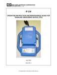
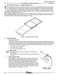
Microflush Half Gallon Toilets
Marine Heads
Air Operated
Model LF-210
Model LF-219
Model LF-310
Model LF-320
Installation/Service Manual
P/N 24533
452 East Hill Road
Willits, CA 95490 USA
Phone: 707.459.5563
Toll Free: 1.800.358.8280
Fax: 707.459.6617
E-mail: [email protected]
www.microphor.com
www.wabtec.com
24533.WPD
10/19/01
THANK YOU FOR PURCHASING A
MICROPHOR® PRODUCT!
Your Microflush® Marine Head is designed to
provide you with years of reliable service while
using only two quarts of salt or fresh water per
flush. Please read this Owner's Manual completely
prior to installation of your Microflush Marine
Head. This will familiarize you with all of the
proper installation and operation requirements.
CUSTOMER SERVICE - Please contact your
local Microphor dealer for parts and service. For a
list of dealers, please contact Microphor at the
addresses listed on the cover of this manual.
AIR SYSTEM
Filter-regulators are
available in a variety of
sizes and types. Their
purpose is to remove
water, oil and other
foreign matter from the air
line and to maintain a
constant pressure at the
toilet of 60-65 PSI. The following steps must be
observed to assure moisture will be removed from
the airline:
1. Drain air compressor receiver regularly. Most
water tends to accumulate at this point.
2. Install drip legs with condensate drains at all low
points in air piping.
3. Whenever possible, grade all airlines back to the
air receiver or drip leg assembly and drain
regularly.
4. The air supply to your Microflush Marine Head
must be taken from the top of the main or branch
air line.
Be certain compressor crankcase has proper oil
levels. Locate the compressor in a clean, dry, well
ventilated location. Size compressor according to
separate Air Compressor Specifications Sheet.
ITEM
LF-210
LF-310
LF-219 LF-320
Air Line Connection Compression
1/2"
3/4" ID
MIPS
Hose
Slip Joint
Barb
Nut
Water Line
Connection
1/4" 45o
Flare Fitting
1/2" FNPT
Fitting
Down
2.25"
(57mm);
12"
3.6"
(305mm)
Not
(91mm)
on centerAvailable
off
line
centerline
Rear
1-1/2" outlet, 3/4"
(19 mm) off
centerline
Drain
Connection
Remote Valve
Assembly
Centerline
Must be mounted so vacuum
breaker is located 6" above rim of
toilet bowl.
1 PRE-INSTALLATION
Following procedures apply
to all Microflush models
unless otherwise noted.
Remove your Marine Head
from box carefully.
Integral Models - Install toilet seat and flush
handle before mounting Microflush to floor.
Seat is not included with LF-210 and LF-219
models. Bolt caps and closet screws are
provided with LF-210 and LF-219 models.
AIR COMPRESSOR
Marine Head Manual P/N 24533
2
June 25, 2002
2 AIR LINES
All piping
supplied by
customer is to
conform to
U.S.C.G.
requirements
relating to
water tight
decks and
bulkhead (46CFR56.69)
INSTALLATION PROCEDURES
4 DRAIN CONNECTION - See Rough-in
Dimensions
For direct overboard discharge, contact
Microphor or your dealer.
When using a 1-1/2" (38.1 mm) discharge line,
each toilet must go individually to the MSD or
holding tank. Do not connect more than one
toilet to a 1-1/2" (38.1 mm) discharge line.
If a vertical rise is required, the vertical rise must
be at the toilet. The maximum vertical rise is
36". The maximum horizontal run is 30 feet
(9.14 meters) and must slope a minimum of 1/8"
per foot (1 in 100) towards the MSD or holding
tank. For 1-1/2" lines, reduce horizontal pipe run
2 feet (.68 meters) per 90o elbow. Use long
sweep elbows, do not use 45o elbows. Do not
use the inverted P-Trap with a vertical rise.
Be sure airline from compressor is of sufficient
size, based on length of pipe run to head. We
suggest 3/8" air line up to 40', 1/2" air line up to
75', and 3/4" air line for over 75'.
Install a filter-regulator assembly in incoming
airline. Place the filter-regulator as close as
possible to the first Microflush Marine Head and
in an accessible location.
When multiple heads are installed, a vented 3"
gravity collection line is to be used with not more
than 4 heads per 3" line. Manifold the 1-1/2"
lines into the 3"collection line and provide a
grade of at least 1/4" per foot towards the MSD
or holding tank. Vent 3" line at the manifold
point.
Set filter-regulator so that 60-65 psi constant is
available at the head. Install an in-line air dryer,
Microphor P/N 30054 or combination
filter/regulator/dryer, P/N 94036.
Assemble the Air Connecting Kit provided and
connect to incoming air line with shut-off valve
between bulkhead and toilet. For LF-210
Models, use Air Connecting Kit P/N 93086, and
for LF-219 Integral Models use Air Connecting
Kit P/N 95172. The plastic airline provided goes
from the air supply to the Flush Activator. On
integral models, the plastic air line enters the
Microflush through the back wall or up through
the floor under the unit. Make sure air is OFF at
air compressor.
DO NOT CONNECT TO FLUSH
ACTIVATOR YET!
Holding tank or MSD must be vertically vented
to atmosphere via 3" vent, terminating at highest
point possible. Limit the number of 45o or 90o
fittings. Do not install loops on end of vent.
For holding tank installations, consider installing
a power fan sized so that a volume of air equal to
the empty tank volume is exchanged every 30 to
60 seconds. The negative pressure shall not
exceed -1.3 psi. This will allow for good air
flow out the vent.
3 WATER LINES
Use a 1/2" water line and install a water shut-off
valve (angle stop) between bulkhead and toilet.
Water at the head must be regulated at an even
pressure between 20 to 50 PSI for Microflush to
operate properly. Optimum pressure is 35 PSI.
DO NOT CONNECT WATER LINE TO
MICROFLUSH YET.
Your Microflush Marine Head discharge line
must have a rise (trap) in order to provide back
pressure during the flush cycle - see Rough-in
Dimensions on pages 14-15.
Caution: Do not apply stress to align
Microflush rear or downward discharge
outlet to waste line. This will result in eventual
damage to seal between Hopper and Toilet Bowl,
causing leaking. Do not use the P-Trap with a
vertical rising waste line.
LF-210 Downward Discharge Model: Rest
Microflush on it's back on a padded surface (e.g.
Marine Head Manual P/N 24533
3
June 25, 2002
shipping box). Center wax ring over Hopper
Flange. Turn Microflush Marine Head over, lift
up, and center it with the horn of the wax ring into
standard floor flange located on centerline 12"
from wall. Compress the wax ring by applying
weight to your Microflush Marine Head. A second
standard wax ring may be added if floor is uneven.
If Hopper Flange hits floor flange, grind it down
for added clearance, as any contact will break seal
between Hopper and Toilet Bowl, causing leaking.
All Rear Discharge Models: Install inverted
P-Trap supplied with Microflush Marine Head. Do
not glue or connect fittings until fitting alignment
has been checked.
Caution: Outlet of LF-210 and LF-219 Models is
3/4" off centerline. Make sure head discharge and
waste line are in line, not off set.
4
5
6
7
Microflush through wall access (maximum 7
feet).
Position toilet and connect hopper discharge
outlet to waste line.
Bolt toilet to floor and attach back plate to wall.
Do not reposition toilet after it is connected to
the waste line as this may break the seal between
bowl and Hopper and cause a water leak.
Re-install side panels on toilet.
Connect the three air supply lines to the
Air/Water Sequence Valve, color coded lines to
matching color coded fittings.
Mount Remote Valve Assembly at least 6" above
the rim of the bowl, and mount the Flush
Activator assemblies at desired location on wall.
5 WATER CONNECTION
Never install a check valve on the inlet side of
the Microflush head.
When using a 1-1/2" discharge line, a vertical lift
of 36 inches can be achieved in single head
applications. The vertical rise must be at the toilet.
This vertical application is not advised for
commercial, high use applications. Do not use the
P-Trap with a vertical rising waste line. Please
contact the factory for further information.
Integral Models - Connect incoming water from
angle stop to water connector. Make sure
WATER IS OFF at angle stop.
LF-210 Models -water supply connector is made
of nylon-plastic. Be careful not to cross threads.
LF-219 Models - if integral model is connected
to a potable water source, the unit requires
installer to provide a Back Flow/Cross
Contamination Prevention device. Please check
applicable jurisdiction for requirements before
installation.
LF-219 Model: For downward discharge, use
molded P-Trap hose supplied. For rear discharge
use inverted P-Trap. See page 9 for part numbers.
Remote Models: Position and mount the Remote
Valve Assembly making sure the Vacuum Breaker
is at least 6" above the rim of the Microflush
Marine Head bowl. Measure air and water lines to
make sure Remote Valve is mounted within
connection distance to Microflush Marine Head.
Run water and the three air lines from the Remote
Valve Assembly to Microflush.
Caution: For Remote Flush Activators, make sure
inside wall thickness does not exceed 1/2" or large
mounting nut will restrict movement of flush
handle.
LF-310 Models - use back-up wrench on water
inlet. DO NOT allow inlet fitting to turn and be
forced into Air/Water Sequence Valve.
Remote Models - Connect incoming water from
angle stop to Microflush Hose Barb on the
Remote Valve Assembly. Connect the water
line from Remote Valve Assembly to the Flush
Rim Spud Assembly. Make sure WATER IS
OFF at angle stop.
Mount toilet bowl to floor. LF-210 and LF-219
models mount to floor with 1/4" closet bolts
provided. Screw on bolt caps to mounting screws.
Model LF-310 and LF-320 models are bolted to
floor, bolts not provided.
LF-320 Models:
1 Remove side panels to facilitate mounting toilet.
2 Connect 7' water line to Spud fitting at the back of
the toilet bowl.
3 Run water and the three air lines from the
Marine Head Manual P/N 24533
4
June 25, 2002
START UP
1 Turn air ON air supply at
compressor.
2 Turn air ON at air
shut-off cock (near but
not connected to Flush
Activator) to blow out
airlines for a few seconds.
This procedure should
remove any debris or contaminants from the
airline. Turn air OFF at shut-off valve.
3 Connect airline to Flush Activator. Make sure air
shut-off valve is installed next to Flush Activator.
Do not over-tighten fittings.
4 Turn ON air shut-off cock. Check total installation
for air leaks using soapy water.
5 Turn ON water. Check for water leaks.
6 Flush you Microflush Marine Head four times,
waiting twenty seconds between flushes to get
water through system and operating regularly. To
flush properly, hold down Flush Activator Handle
or Button until flapper opens.
Standard Positive -
hold handle or button down for 1
second.
barely push handle or button to
activate.
CLEANING BLEED-OFF PLUG
ASSEMBLY
Standard Flush:
Remove plug and clean with solvent; air blow dry.
Positive Flush:
Remove plug and clean with solvent; air blow dry;
remove and clean plug on Detent Valve.
Note: Use 5/32"or 4mm Allen wrench to remove
plugs.
DOUBLE CHECK
1 Air pressure at Microflush Head is at 60-65 psi.
2 Water Pressure at Microflush Head is between
20-50 psi, 35 psi optimal.
3 Water level in bowl should be at top edge of
flapper opening.
If your Microflush does not operate correctly, refer
to troubleshooting sections.
Note:
Bleed-Off Plugs on Air & Water Sequence Valves
and Detent Valves are different sizes that are not
interchangeable.
FLUSH CYCLE ACTIVATORS
MAINTENANCE/CLEANING/CLEARING/
WINTERIZING
There are two types of Flush Activators:
ROUTINE MAINTENANCE
Marine Head Manual P/N 24533
5
June 25, 2002
Your Microflush Marine
Head has an air-operated
USAGE LUBRICATE
Air/Water Sequence
Light
Every 5 years
Medium Every 2-3 years
Valve which requires
Heavy
Every year
periodic lubrication with
a silicone based
lubricant. Check your
application at right to
determine how often to
lubricate your Air/Water Sequence Valve. The Air
Cylinder should be serviced if you have to take up
your Microflush Marine Head for any reason. The air
system must be free of moisture. Drain air
receiver regularly to remove moisture.
CLEANING
Use Micro-Clean Organic Spray Cleaner, P/N 24542.
Sanitizers like Lysol, Pine-Sol, Hexol, ammonia
base products, caustic drain openers or
non-biodegradable cleaners should never be used if
the plumbing system is connected to a Microphor
MSD.
1 While depressing the Flush Activator, turn OFF the
water. Allow the bowl cleaner to flow into the
lower chamber. Keep the Flushing Activator
depressed.
2 Insert bowl brush into lower chamber and agitate
mixture carefully. Remove the bowl brush and
release the flush activator.
3 Turn the water ON and flush twice to rinse
thoroughly.
NOTE: LF-310 or LF-320 Stainless Heads may be
subject to surface rusting, especially if salt water is
used for flushing and if bleach or a corrosive product
or cleaner is left standing in or on the bowl. The salt
water will enhance the oxidation qualities of the
bleach (or product containing bleach). If it sits on the
stainless and the surface remains damp, the chrome
and nickel will etch out of the stainless, leaving ferrite
iron, which will rust. If bleach or any cleaner is used,
it must be well rinsed, not left standing (soaking) in
the bowl or on the toilet, especially in toilets using salt
water.
CLEARING YOUR MICROFLUSH HEAD
If your Microflush Marine Head becomes plugged,
shut off the water supply, press the flush handle and
hold. The flapper will remain open until flush
handle is released. Check to see if the restriction
can be removed from lower portion of Microflush
Marine Head with a hooked wire, being careful not
to damage the rubber seal on the flapper or the
mating surface on the hopper. If obstruction cannot
be picked out with a hook or tongs, use plunger by
pushing in slowly and pulling out quickly to pull
object back into the hopper. If necessary, turn air
off and use a snake inserted through a short plastic
pipe placed in hopper. Pipe will protect flapper
seal. If valve will not operate with water off, hold
flush lever down and turn water on and off quickly
to free valve action. When the passage becomes
clear, turn on water and press flush handle to start
flush cycle.
WINTERIZING (out-of-service winter storage)
Shut OFF water to Microflush Marine Head. Flush
Microflush Marine Head three times or until water
no longer flows into the bowl. Unhook water supply
at angle stop. Empty water in line into receptacle.
Shut OFF air supply to your Microflush Marine
Head. The unit is now prepared for freezing
temperatures. OPEN petcocks on drip legs and air
receiver drain after shutting down air compressor
and isolating airlines. Use of Anti-freeze is not
recommended.
PATENTS
Microflush® Toilets are covered by one or more of
the following U.S. patents: 5245710; 4918764;
1280554; 169471 and related foreign patents.
WARNINGS
Do not use any petroleum based lubricants
(Vaseline) on any rubber parts or o-rings
as damage will occur. Use only silicone
based lubricants.
Do not use any ‘Locktite’ brand adhesives on any
plastic or Delrin components as fumes will
cause damage.
Do not use Teflon tape on any air fittings as
clogging may occur.
DESIGN CHANGES
Continuing a policy of research and development,
Microphor reserves the right of price, product or design
change without notice or obligation.
Marine Head Manual P/N 24533
6
June 25, 2002
TROUBLESHOOTING
Your Microflush® toilet is designed to give you years of trouble-free operation. Please check the following
before beginning any service or repair:
Water supply: 1 Is the water turned on?
2 Is the water pressure between 20 and 50 psi at the toilet for pressure water system?
3 Is there 6 feet minimum of head for gravity systems?
Fluctuating or high water pressure can cause intermittent problems with the toilet operation.
Check the water pressure at different times of the day (i.e., early morning, noon, evening) to
determine if you have fluctuating or high water pressure. A pressure-reducing valve installed on
the incoming water line will assure you have even pressure. Make sure no check valve is
installed before the Air/Water Sequence Valve.
Air system:
1 Is the air turned on?
2 Is the air pressure set at a constant 60-65 psi at the toilet?
3 Do you have any air leaks or kinks in the air system?
4 Do you have water in the air system? This usually causes irregular timing.
Drain the compressor tank and check the filter regulator and drip leg(s) for water. To check for
water in Air/Water Seq. Valve, remove Bleed-Off Plug, put finger over screw opening and flush.
If water is present, it will squirt out. If water is detected, then the air cylinder and airlines must
also be drained.
Cycle time:
1
2
Is the flapper cycle time set correctly at 4-8 seconds?
Is the bleed off assembly plug blocked? Remove, clean and reinstall (see page 5).
Trouble
Possible Causes
Correction
Flapper does not open.
Water does not flow.
Nothing happens.
1 No Air Supply to Microflush.
2 Water has accumulated in
Air/Water Sequence Valve
1 Supply compressed air at 60-65
psi at the toilet
2 See 'Check Air System" above.
Flapper opens and closes 4-8
seconds after handle is released,
but no water enters bowl.
1 No water supply to Microflush.
2 Water turned off.
1 Supply water at 20-50 psi.
2 Open angle stop (shut-off
valve).
Flapper opens when flushed, and
closes immediately when activator
is released.
1 Excessively high water
pressure.
2 Debris in check valve at base of
Air/Water Sequence Valve.
1 Install water pressure
regulating valve, set at 20-50
psi.
2 Clean Air/Water Seq. Valve.
Flapper opens and will not close.
Bleed Off plug blocked.
Remove, clean or replace,
reinstall.
Water continues to run when
Microflush is not in use.
Foreign object is under water
valve in Air/Water Sequence
Valve.
Clean Air/Water Sequence Valve.
Reference Service Kit P/N 95057.
Water splashes when flushed.
Water is too high in bowl.
Reduce incoming water via angle
stop.
Flush cycle is too long.
Bleed-Off Plug blocked.
Remove, clean or replace,
reinstall.
Flush cycle is too short.
Air line leakage.
Check for air leakage at all
connections.
If other problems are encountered, please contact the factory: Toll Free: 1-800-358-8280
Marine Head Manual P/N 24533
7
June 25, 2002
EXPLODED VIEWS
A
B
C
D
E
F
G
H
I
J
K
L
M
N
O
P
Q
R
S
T
U
V
W
X
Toilet Shell
Toilet Lid
Closet Screws
Flush Activator
Air/Water Seq.
Valve
Vacuum Breaker
Bleed Off
Assembly
Valve Bracket
Hopper
P-Trap, Rear
Discharge
Hopper Mounting
Assembly
Marine Bleed
Valve
Hopper Screws
Air Cylinder
Flapper Assembly
Crank Assembly
Spud Assembly
Water Supply
Tube
Water Connection
See chart on next page
See chart on next page
Hopper Gasket
Air Supply Kit
Pressure Relief Valve
Marine Head Manual P/N 24533
Typical Remote Assembly
8
June 25, 2002
Marine Head Manual P/N 24533
9
June 25, 2002
PARTS CHART
MODEL
PART
LF-210 China
Round
LF-210 China
Elongated
LF-219 China Round
Integral & Remote
LF-310 SS
Round
LF-320 SS
Round
A
Toilet Shell
44032 - white
colors - see
chart
44010 - white
colors - see
chart
44151 - integral, white
44133 - remote, white
colors - see chart
93082 - shell
93084 - top shroud
93085 - bottom
shroud
colors - see chart
93008 - shell
colors - see
chart
B
Toilet Lid
99064 - white
99073 - bolt down, white
colors - see chart
C
Closet Screws
& Bolt Caps
93972 - white
colors - see chart
D
Flush Activator
95002 - standard
95054 - positive
E
Air/Water
Sequence Valve
39501 - no fittings
F
Vacuum
Breaker
33559 - integral
33039 - remote
G
Bleed-Off Plug
Assembly
94598
H
Valve Bracket
91897 - integral
20003 - remote
I
Hopper
90016-3 - rear
90008 - downward conversion kit
Not applicable
Not applicable
40046-5/40049-5 int, wht
40046-9/40049-9 int, blk
40046-7/40049-7 int, bone
95151 - remote
95561 - standard
95031 - standard
33421 - check valve
33039 - remote
96539 - integral
33039 - remote
30382-3
94598
91866 - integral
20003 - remote
Not applicable
20003 - remote
90016-3 - rear
95157 - downward hose
90039 - 3 rear
40050-3 Tank isolation valve
40050-3 tank isolation valve
27282 - Hopper Adaptor O-ring
J
P-Trap, Rear
Discharge
96029
K
Hopper
Mounting Assy
90899-5
L
Hopper Bleed
Valve
37548
M
Hopper Screws
00064 (14 each)
N
Air Cylinder
94540
O
Flapper Assy
90048
P
Crank Assy
90042
Q
Spud Assy
96347
95155
96579
R
Water Supply
Tube
96012 - integral
35053 - remote
35484 - integral
35484 - remote
96002
96008
S
Water
Connection
96387
N/A - integral
33352 - remote
96515
33352
T
Air Fittings
30385 - 90E Elbow, 30365 - Straight
U
Air Tubing/ft
green - 35381, blue - 35382, red - 35383, yellow - 35384, white - 35385, black - 35419
V
Hopper Gasket
27272
27270
W
Air Supply Kit
93086
N/A
X
Pressure Relief
Valve
37518
Marine Head Manual P/N 24533
00006 (4 each) and 00106 (4 each)
00064 (10 each)
10
June 25, 2002
COLOR CHART - AIR LINE CONNECTIONS - SERVICE KITS
VITREOUS CHINA COLOR CHART
LF-210
LF-219
Color
Code
Round
Shell & Lid
Elongated
Shell & Lid
Lid
Only
Remote
Shell
Integral
Shell
White
--
44032
44010
99064
44133
44151
SC1
44327
44328
99064-23
44133-3
44150
Bone/Natural
S4
44039
44012
99064-3
44134
44152
Harvest Beige
SC4
44333
44334
99064-15
NA
N/A
Pink
SR2
44331
44332
99064-21
NA
N/A
Grey
651
44329
44330
99064-5
44135
44153
Black
N-5
44337
44338
99064-7
44130
44154
Pastel Ivory
AIR LINE CONNECTIONS
From Air/Water
Sequence Valve
To
Red, P/N 35383
Air Cylinder, bottom fitting
White, P/N 35385
Air Cylinder, top fitting
Black, P/N 35419
Bleed Off Plug
Green, P/N 35381
Flush Activator, front fitting
Blue, P/N 35382
Flush Activator, back fitting
Yellow, P/N 35384
Hopper
SERVICE KITS
# P/N
Description
1
93100
Master Service Kit (2-5 below)
2
95057
Air/Water Sequence Valve
3
94502
Air Cylinder
4
95020
Flush Activator Pilot Valve (standard)
5
95037
Vacuum Breaker
6
95122
Positive Flush (Detent) Valve
7
90066
Flapper Replacement Kit
8
90070
Hopper Conversion Kit - Rear
9
90071
Hopper Conversion Kit - Bottom
Marine Head Manual P/N 24533
11
June 25, 2002
HOPPER REPLACEMENT
Model LF-210 and LF-219 Models Only
CAUTION:
Read this entire procedure
before beginning work!
1. Remove toilet from floor. Place toilet
upside down on a sheet of cardboard or
other padded material.
2. Remove nuts from J-bolts on either side
of hopper, lift hopper from bowl.
3. Remove o-ring between hopper and seal
adaptor. Check that o-ring is not
damaged, replace if necessary.
4. Re-assemble in reverse order.
MAKE SURE J-BOLTS ARE TIGHT!
Proper torque specification is 4-6
inch/lbs.
Note: The air cylinder on the hopper sub-assembly should be cleaned, lubricated and checked for adjustment
whenever the toilet assembly is removed for servicing.
TANK ISOLATION VALVE INSTALLATION (Not supplied with toilet.)
Note:
Check valve halves for tightness before
installing.
Rear Discharge with LF-219 Downward Hose
Install Tank Isolation Valve Assembly in line
at the end of the discharge hose using a 1-1/2"
long pipe nipple.
Rear Discharge
Glue tank isolation valve assembly to hopper at
point indicated.
Bottom Discharge, No Flange
Glue Tank Isolation Valve Assembly directly
to hopper discharge as indicated.
Bottom Discharge with Flange (1-1/2" pipe)
Glue 1/2" long pipe nipple to hopper discharge
port as indicated, and glue Tank Isolation
Valve assembly to pipe nipple.
NOTE: Isolation Valve is in two pieces;
tighten valve before installation and
again before making drain connection!
Marine Head Manual P/N 24533
12
June 25, 2002
AIR CYLINDER ADJUSTMENT
1
2
3
4
5
6
7
Remove Hopper (see Hopper Replacement).
Remove the clevis pin retaining ring. Remove the clevis pin.
Inspect the crank arm, clevis and clevis pin for wear. Replace if required.
Hold the crank arm in the UP position (flapper closed).
Fully extend the air cylinder and note the position of the holes in the crank arm and the clevis. The clevis
hole should extend half its diameter past the crank arm hole.
Adjust as necessary by loosening the locknut and extend or retract the clevis as required.
Re-install Hopper.
TO CHANGE FLAPPER GASKET:
1. Turn water and air off.
2. Reach behind flapper to grasp gasket tails.
3. Pull tails out of slots to remove old gasket.
4. Installation is the reverse of removal.
5. Tails must be pulled all the way through to insure smooth surface.
AIR/WATER SEQUENCE VALVE
COMPONENTS
Components shown in italics are part of Kit,
P/N 95057.
Spacers and Spool available as a set, P/N
95530.
Water Body, Main Body and Bottom Cap
available as a set, P/N 39386.
Marine Head Manual P/N 24533
13
June 25, 2002
AIR/WATER SEQUENCE VALVE OPERATION
Marine Head Manual P/N 24533
14
June 25, 2002
ROUGH-IN DIMENSIONS: LF-210, LF-310 and LF-320 Models.
Reference Remote Flush Rough-In, next page.
ROUGH-IN DIMENSIONS: LF-219 Models
Marine Head Manual P/N 24533
NOTE: All dimensions may vary ½"±
NOTE: All dimensions may vary
15
June 25, 2002
½"±
NOTE: Do not use P-Trap in vertical rise waste line applications.
Marine Head Manual P/N 24533
16
June 25, 2002
Terms & Conditions here
Marine Head Manual P/N 24533
17
June 25, 2002