1
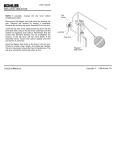
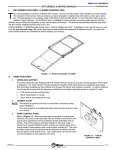
Microflush Half Gallon Toilets
Model LF-220
DC Operated
Installation/Service Manual
P/N 24155
452 East Hill Road, Willits, CA 95490 USA
Tel: 707.459.5563 Tel: 800.358.8280 Fax: 707.459.6617
www.microphor.com www.wabtec.com
Thank You!
Flush Cycle Operation
Thank you for purchasing a Microphor product. Please
read this manual completely prior to installation of your
Microflush® toilet. Microphor General Terms and Conditions Covering Sales apply.
The Model LF-220 Microflush Toilet is an electrically
operated drop-through type toilet using approximately
two quarts of water per flush. Wastewater is flushed
from the bowl through a Hopper and drops directly into a
holding tank. A Flapper valve at the bottom of the bowl
holds fresh water in the bowl and seals out odors from
the holding tank.
1. When the flush lever is operated, a motor-driven cam
begins to turn which opens the Flapper valve at the
bottom of the bowl, allowing the wastewater to flow
down into a holding tank. Simultaneously, the water
solenoid valve opens, allowing fresh water to flow
from the rim and rinse the bowl. The cam continues
to turn and the Flapper will close again after approxi
mately 4-5 seconds.
2. After the Flapper has closed, fresh water continues to
enter the bowl to a predetermined level until the
Timer closes the solenoid valve. An adjustment on
the Timer allows adjustment of the water level in the
bowl to compensate for water pressure fluctuations.
A vacuum breaker is provided as an anti-siphon
device.
Customer Service
If you have any questions concerning your Microphor
product, please contact us:
8:AM-5:PM PST Monday-Friday
Tel: (800) 358-8280 or (707) 459-5563
Fax: (707) 459-6617, 24 hour
Website: www.microphor.com
Patents
Microflush toilets are covered by one or more of the
following U.S. patents 5245710; 4918764; 1280554;
169471 and related foreign patents.
Changes in Design
Continuing a policy of research and development,
Microphor reserves the right of price, product or design
change without notice or obligation.
Flush Cycle
Cautions
Do Not Use products containing petroleum distillates or
formaldehyde on any rubber parts.
Use only Silicone Lubricants!
Do Not Use any “Loctite” brand adhesive on any plastic
or Delrin components as fumeswill cause damage to
plastic parts. System vacuum breaker is not intended to
be pressurized longer than a normal flushing cycle.
System vacuum breaker is not intended to be
pressurized longer than a normal flush cycle.
Model LF-220 Downward Discharge (All dimensions +/- 0.5")
File: 220-SPEC
Elongated 26.5"
16.43"
Round 24.5"
Water Hook-Up
1/2" Straight
Pipe Thread
13"
3.38"
18.75"
Electrical
Connection
Finished
Wall
13.25"
8.69"
Cutout at Rear
15"
7.75"
15.5"
2
Toilet Discharge
3 1/2" O.D. Pipe Size
to accomodate Floor
Flange
22"
Foot Print
Mounting
Holes (4)
File: 24155
Rev: 04/05
Installation
Water Level
Refer to Rough-In Dimensions
Note: This toilet is a drop-thru unit. No
horizontal waste line runs may be utilized.
Contact the factory for specific application
data.
The normal water
level is factory preset to the top of the
Flapper.
Recommended
Water Level
Water Level
Adjustment
Mounting Toilet
Turn toilet upside-down and place enclosed Wax
Ring (P/N 27208), onto the bottom of mouting
flange of the toilet hopper. Carefully turn toilet
right-side up and place over the center of a standard
floor discharge flange. Press toilet down firmly
and evenly to form a seal between the wax ring and
the floor flange. Mount the toilet to the floor with
the four Closet Screws and install Bolt Caps over
the closet screws (both provided).
Locate the timer on the
bracker under the china
lid. Turn Timer adjustment knob clockwise to
increase water level, and
counterclockwise to
decrease. Do not turn
past stops.
4
6
8
2
6
0.1
1
SECONDS
10
3
2
File: Timer
Seat Installation
Electrical Connection
Place the seat over the bowl opening, so that the
mounting hinges on the seat align with the two
holes in the bowl just behind the bowl opening.
Insert the two seat mounting screws provided with
the seat into the hinges’ holes and mounting holes
in the bowl, from the top. Install washers and
mounting nuts provided with the seat, from underneath, and tighten firmly. Install screw head cover
tabs or other hardware provided with the seat, per
seat manufacturer’s instructions.
See Rough-In Dimensions and Exploded View.
Connect 12 volt DC power source to the insulated
.25” spade connector near the Timer and Thermal
Circuit Breaker: red wire to positive (+), black wire
to negative (-).
Water Connection
See Rough-In Dimensions.
Connect fresh water from an angle stop to the 1/2”
threaded water supply connection on the side of the
bowl installing Filter Screen (P/N 29146). Take
care not to cross the threads. Incoming water
pressure must be between 20-50 PSI, with a
minimum flow rate of 2.5 GPM at the toilet.
Ideal water pressure is 35 PSI at the toilet. Be
sure water lines are free of debris before connecting
water supply to toilet. Water supply to the toilet is
to be 1/2” OD plumbed directly to the toilet. Do
not install filter(s) in the toilet water supply line.
Maintenance
If the toilet is to be out of service for a period of
time, spray 100% silicone on the flapper seal when
the flapper is open to prevent if from becoming dry.
Winterizing
Shut OFF water to toilet. Flush toilet three times or
until water no longer flows into the bowl. Unhook
water supply at angle stop. Empty water in line
into receptacle.
3
File: 24155
Rev: 04/05
Ordering and Factory
Circuit Breaker
Switch allows
Assistance
power to be
For assistance with procedures not covturned off to
ered in this manual, or to order spare or
Electrical service toilet.
replacement parts, please call toll free
H Connection
800-358-8280, 8:00 a.m. to 5:00 p.m. PST,
and ask for Commercial Products Division
F
Customer Service.
B
E
Q
A
Overflow Water Lines (optional, depending upon model)
D
G
R
Overflow Elbow
On Hopper
End Attaches To
Vacuum Breaker
S
A loop is necessary
for proper function
Water
Connection
1/2" NPT
To Overflow Elbow
On Hopper
L
File: Overflow
Customer
Electrical Connection
C
I
42042 Thermal
Circuit Breaker
Black (-)
Red (+)
95104
Flush Activator
89142 Water
Level Adjustment
File: 220-ExpB
J
K
ow
Blue
ll
Ye
Blue
41983 Switch
ow
ll
Ye
Red
99086 Motor
Bracket Assy
Solenoid
le
Voi
t
le
Voi
41982 Cam
Limit Switch
White
41981
Motor
t
File: 320-12VDC-WIRE-1
Violet
Flush Activator
Limit Switch
Violet
Yellow
Level
Adjust
Red
+
Yellow
6
5 4
Timer
1 2
3
Thermal Circuit
Breaker
M
White
Motor
Red
Blue
Black
Blue
12VDC
Vehicle Power Source
Solenoid
4
File: 24155
Rev: 04/05
Parts Chart
PART
P/N
A
Bowl - state color
Call
B
Lid - state color
Call
C
Mounting Bolts - state color
Call
D
Flush Activator
E
Timer Assembly
Complete Assembly
9 5 10 4
Switch
41983
Mounting Nut
00098
O- Ring
27232
Timer
8 9 14 2 *
Thermal Circuit Breaker Switch
42042
F
Vacuum Breaker Assembly
see Vacuum Break er Serv ice
33540
G
Solenoid Vavle Assembly
see Solenoid Valv e Cleaning
89134- 3
H
Mounting Bracker
I
Hopper Assembly
see Hopper
see Flapper Adj ust ment
Motor Assemlby
see Flapper Adjustment
see Clevis exploded view
see Wiring Schematic
9 10 2 2
Hopper Assembly without Motor
90056
Hopper Assembly with Motor Assembly
90028- 3
Motor
41981
Cam with Set Screw
91865*
Motor with Bracker Assembly
99086
Limit Switch
41982*
Wax Ring
27208
J
Floor Seal
K
Hopper Mounting Assembly (J- Bolts)
90899- 3
L
Overflow Assembly
96385
Q
Spud Assembly
R
Water Supply Tube
Complete Assembly
96347
O- Ring
27224
Complete Assembly
96392
Elbow
96387
S
Water Filter Screen
92060
K
I
T
S
Flapper Replacement Kit
90066- 3*
Hopper Adapter Kit
24770- 3
Solenoid Valve Service Kit
40037*
Vacuum Breaker Service Kit
95037*
Silicone Lubricant
26856
Master Service Kit
9 4 17 5
*Items shown with asterisk are in Master Service Kit, P/N 94175
5
File: 24155
Rev: 04/05
Service Procedures
Before performing any service procedures, turn off water and electrical power to toilet.
Flapper Adjustment
Flapper Replacement Kit, P/N 90066-3
1.
2.
3.
Flapper Adjustment
Remove toilet from floor. Locate flapper operating linkage on the side of the
hopper.
Remove the clevis pin retaining ring. Remove clevis pin.
Adjust as necessary by turning the 3/8” set screw inside the clevis as
required, then replace the clevis pin and retaining ring. Turn clockwise to
increase flapper seal tension, counterclockwise to
Adjustment Set Screw
with Spring Inside
decrease. Inspect the crank arm, clevis and clevis
P/N 37016
Clevis Pin
pin for wear; replace if required. Do not turn bolt
more than three (3) complete turns.
91865 Cam & Set Screw
More
P/N 10194
Retaining Ring
Turn water and air off.
Reach behind flapper to grasp gasket tails.
Pull tails out of slots to remove old gasket.
Installation is the reverse of removal.
Tails must be pulled all the way through to insure smooth
surface.
Timing
Notch
File: Clevis
41982
Limit Switch
File:Motor
Mounting Plate
Adjustment Screw
2.
3.
4.
5.
6.
7.
00818 Thumb Nut
Diaphragm
Poppet
Spring
Solenoid Valve Cleaning
Solenoid Service Kit, P/N 40037
1.
41981
Motor
99084
Clevis Assy
P/N 37017
Clevis
To Change Flapper Gasket
1.
2.
3.
4.
5.
Adjustment Set Screw with Spring Inside
Less
Disconnect the power by removing the two (2) blue wires from the
solenoid.
Disconnect the water supply line at china end.
Remove two (2) screws securing the solenoid to the mounting
bracket.
Pull solenoid away from the Vacuum Breaker.
Remove water supply line.
Remove four (4) screws from Solenoid Valve Body and remove
spring and diaphram.
Clean holes in the diaphram if clogged. Inspect solenoid for debris
and clean. Reassemble in reverse order.
File: 320-12VDC Solenoid
CHINA HOPPER HORN
SEALING ADAPTOR (Glued to China Horn)
QUAD RING, P/N 27022 OR P/N 27282
HOPPER
Hopper Removal and Resealing
Hopper Replacement Kit, P/N 24770-3
1.
2.
3.
File: Hop-12vb
Remove toilet from the floor. Place toilet upside down on a sheet of cardboard or
other padded material.
Remove J-Bolts nuts from hopper sides - life the hopper off.
Remove quad ring between hopper and seal adaptor. Check that the quad ring is not
damaged, replace quad ring if necessary.
Vacuum Breaker Service
Vacuum Breaker Service Kit, P/N 95037
1.
2.
3.
Vacuum Breaker
15803, Cap
Vacuum
Breaker
Service
Kit
P/N 95037
15880, Top
27221, O-Ring
27256-3, Float
If water is visible at the top of the vacuum breaker during operation, apply some
silicone lubricant to the underside of the white float and to the O-Ring located at the
upper end of the body.
To disassemble the vacuum breaker, remove the snap-on cap and unscrew body from
the bracket. The white float inside can now be removed.
No service procedures are required for the lower portion of the vacuum breaker.
6
Hold Down Nut
Base
File: 95037
File: 24155
Rev: 04/05
Troubleshooting Guide
Problems
Cause
Remedy
Water drains
from bowl
Nicks or obstructions on Flapper seat
Replace Flapper, Service Kit P/N 90066- 3
Insufficient Flapper tension
See Flapper Adjustment
Flapper seal worn or damaged
Replace Flapper - Kit P/N 90066- 3
Water level control out of adjustment
Turn Level Adjustment 1/8 turn at a time to raise or lower
water level; Clockwise to raise, counterclockwise to lower.
Fluctuating water pressure
Regulate water pressure
Timer malfunction
Replace Timer - Reference Timer drawing
Water continues
to run
Obstruction in water Solenoid Valve
Remove and inspect Solenoid Valve
- see Solenoid Valve Cleaning
Toilet continues
to cycle after
initial flush cycle
is complete - or
only partially
cycles
A cracked cam
Replace cam
- reference Flapper Adjustment Drawing
Defective Cam Switch; switch out of adjustment
Adjust or replace Cam Switch
- reference Flapper Adjustment Drawing
Defective Timer
Disconnect either purple wire at limit switch. If toilet
continues to cycle, the timer is defective. If the toilet stops
cycling, the limit switch either is not adjusted properly or is
faulty.
Water level too
high
Water leaking on The hopper has been jarred loose from the bowl
floor
No water
Toilet doesn't
activate
Water is visible
at Vacuum
Breaker when
flushed
Reseal Hooper
- see Hopper Removal/Reseal
Defective wax ring at toilet to floor connection
Replace the wax ring
Loose water supply connection at toilet
Disconnect water line to toilet, add Teflon tape to threads,
reconnect
Water turned off
Turn water on
Water inlet filter screen clogged
Clean water inlet filter screen
No power to valve
Check for DC power at Solenoid Valve during flush cycle
Defective Timer
Check Timer operation - replace if necessary
No power
Restore power
Tripped Circuit Breaker
Reset Circuit Breaker Switch. Determine cause of tripped
breaker if possible before operating toilet
Disconnected wires
Check all wiring connections
Insufficient lubrication; Worn vacuum breaker seal
Service Vacuum Breaker Kit, P/N 95037
If you have any questions or need assistance, call 800.358.8280
Changes in Design: Continuing a policy of research and development, Microphor reserves the right of price, product, or design
change without notice or obligation.
7
File: 24155
Rev: 04/05
General Terms and Conditions Covering Sales
All sales of merchandise by Microphor are subject to the General Terms and Conditions as provided herein and on invoices issued by Microphor.
PRICES: All goods and products sold by Microphor will be billed to its customers according to the price lists contained in the current bulletins and
price lists issued by Microphor. All prices are subject to change without notice and supersede all prior price lists. Microphor assumes no
obligation to sell to anyone at any price or at any of the terms listed herein.
TERMS: Customer orders will be accepted subject to credit investigation, and approval, and delivery may be withheld on accepted orders, other
than cash in advance, without any liability on the part of Microphor if, in its opinion, there is doubt concerning the ability of the customer to pay for
merchandise ordered under the terms and conditions contained in current bulletins and price lists issued by Microphor. After delivery of merchandise, should Microphor, at its sole discretion, institute legal action for collection, customer agrees to pay all attorney fees and costs incurred by
Microphor by reason of such action.
FREIGHT AND DELIVERY: PRICES ARE F.O.B. FACTORY: Delivery to the initial carrier shall constitute delivery to the customer. Microphor’s
responsibility ceases upon delivery in good order to the carrier and all goods are shipped at the customer’s risk. Customer shall be responsible
for filing a claim with carrier. Microphor shall not be liable for any delay or failure in the delivery or shipment of merchandise against an accepted
order or for any damages suffered by reason thereof when such a delay or failure is, directly or indirectly, due to accident (in manufacture or
otherwise) fire, flood, riot, war, embargo, labor stoppage, delays in transportation, inadequate transportation, shortage of materials or supplies,
regulation by Government authority or any like or dissimilar cause or causes beyond the control of Microphor. Shipping weights and freight
estimates given are approximate, for customer’s convenience only, and are not guaranteed.
SHORTAGES OR VARIANCES: No claims for variances from or shortages in orders will be honored unless presented within fifteen (15) days
after customer’s receipt of order.
CANCELLATION OF ORDERS: After a purchase order has been provided by customer, written or oral, an order may be modified canceled
only upon written confirmation by Microphor. Additional costs incurred by Microphor as the result of modification or cancellation will be billed to
customer. Orders for merchandise requiring special manufacturing or supervision, or articles of a special nature, will not be canceled after
production is commenced.
TAXES: Taxes, whether local, state or U.S. government now in effect, or hereafter levied, upon the product, sale thereof, use, shipment, or
otherwise, of goods ordered or sold shall be charged to and paid by customer.
CHANGES IN DESIGN: Factors beyond the control of Microphor, the need for continuing improvement of product for competitive reasons, or
for any other reason, may require changes from time to time in products and their packaging. Microphor reserves the right to make such changes
of any kind, at any time, without notice. Microphor may also, from time to time discontinue the sale of its products, without notice.
LIMITED WARRANTY: Microphor warrants its products to be free from significant defects in material and workmanship under normal use and
service for a period of two (2) years from the date of purchase, by the original purchaser. THE OBLIGATIONS OF MICROPHOR UNDER THIS
WARRANTY are limited to the repair or replacement, at Microphor’s option, of defective parts of the product which shall, within two (2) years from
the date of purchase, (Note: certain air compressors and their parts, oily water seperators and their parts are warranted for one (1) year from date
of purchase.) be returned with proof of purchase to Microphor’s factory, Willits, CA, TRANSPORTATION CHARGES PREPAID. When it is
impractical to return the defective parts of such products to Microphor’s factory, then Microphor shall be liable solely for supplying the material
necessary to replace or repair the defective parts. WHILE MICROPHOR WILL NOT CHARGE FOR LABOR IN CONNECTION WITH WARRANTY REPAIRS OR REPLACEMENTS MADE AT ITS FACTORY, MICROPHOR AT ITS SOLE DISCRETION MAY CHARGE FOR LABOR AND
EXPENSE INCURRED BY IT IN CONNECTION WITH WARRANTY REPAIRS MADE AT THE CUSTOMER’S PLANT OR LOCATION. In any
event, Microphor reserves the right to determine whether or not a defect exists for which it is responsible under this warranty. A returned material
authorization must be obtained from Microphor Customer Service prior to the return of any merchandise. This warranty is void if the product has
been damaged by customer prior to acceptance or as a result of unreasonable use, neglect, alteration, improper service, improper installation or
other causes not arising out of defects in material or workmanship or if any serial number on the product has been altered or defaced.
MICROPHOR SHALL NOT BE RESPONSIBLE FOR LOSS OF USE OF PRODUCT OR OTHER INCIDENTAL, SPECIAL OR CONSEQUENTIAL
DAMAGES INCURRED BY PURCHASER INCLUDING BUT NOT LIMITED TO PERSONAL INJURY AND PROPERTY DAMAGE.
This warranty is in lieu of all other warranties express or implied, including without imitation, any implied warranties of merchantability or fitness for
a particular purpose, and Microphor neither assumes nor authorizes any representative or any other persons to assume for it any other liability in
connection with the sale of its products. Microphor makes no warranties, express or implied, with respect to parts, accessories, components or
other goods not manufactured by Microphor.
CONTRACT WITH CUSTOMER: No terms and conditions of a customer’s order at variance with Microphor’s General Terms and Conditions
and/or its invoice shall be binding upon Microphor unless specifically agreed to by Microphor in writing. In acknowledging any order, any and all
terms and/or conditions of customer’s order or correspondence contrary to those of Microphor are to be deemed waived by customer.
PATENTED PRODUCTS: Certain Microphor products and processes are patented (or patents are pending) under U.S. and foreign patents.
Manufacture, reproduction or practice of such products, or processes without prior written authorization from Microphor may result in liability for
patent infringement.
8
File: 24155
Rev: 04/05