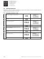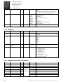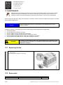
1
English Original instructions SERVICE MANUAL FOR FREQUENCY CONTROL SYSTEM ControlMaster® LDR - - - 159852 12.2013 DOC_SM_TDN0300100-0 PS18733 11/13/2029 SUPDOC_SM_TDN030-0.ORD 20/12/2013 R&M Materials Handling, Inc. 4501 Gateway Boulevard Springfield, Ohio 45502 P.: (937) 328-5100 FAX: (937) 325-5319 Table of contents 1 2 UPDATE HISTORY ............................................................................................................................ 4 GENERAL INTRODUCTION .............................................................................................................. 5 2.1 2.2 2.3 2.4 2.5 2.6 2.7 2.7.1 2.7.2 3 Foreword: About this manual ........................................................................................................................5 Symbols Used in this Manual .......................................................................................................................5 Safety Alert Symbols and Signal Words .......................................................................................................5 Questions and Comments ............................................................................................................................6 Manual Use ...................................................................................................................................................6 Terminology ..................................................................................................................................................7 Directives and standards ..............................................................................................................................8 CE/CSA/UL/CCC ......................................................................................................................................8 EMC ..........................................................................................................................................................9 SAFETY FIRST! ............................................................................................................................... 10 3.1 3.1.1 3.2 3.3 3.4 4 Personal protective equipment (PPE) .........................................................................................................10 Fall Protection .........................................................................................................................................10 Fire Safety ...................................................................................................................................................11 Main isolation switch ...................................................................................................................................11 Safety during maintenance .........................................................................................................................11 IDENTIFICATION............................................................................................................................. 13 4.1 Manufacturer ...............................................................................................................................................13 4.1.1 Main sticker .............................................................................................................................................13 4.2 Factory code example (Factory: TDN) ........................................................................................................14 4.3 R&M code example (R&M: ControlMaster® LDR, Factory: TDN) ..............................................................15 5 6 TECHNICAL DATA .......................................................................................................................... 16 CONSTRUCTION ............................................................................................................................ 17 6.1 Intended use of the frequency converter ....................................................................................................17 6.2 Main components ........................................................................................................................................18 6.2.1 Control panel ...........................................................................................................................................19 6.2.2 Terminal for program Connection Tool for TDN .....................................................................................19 6.2.3 Terminals ................................................................................................................................................20 6.2.4 Braking resistor .......................................................................................................................................25 6.2.5 EMC Filter ...............................................................................................................................................26 7 PREPARING THE PRODUCT FOR USE ......................................................................................... 29 7.1 Transport and storage.................................................................................................................................29 7.2 Safety precautions before installation .........................................................................................................29 7.3 Mounting .....................................................................................................................................................30 7.3.1 Dimensions .............................................................................................................................................30 7.3.2 Mounting .................................................................................................................................................31 8 USER INTERFACE .......................................................................................................................... 33 8.1 8.2 8.2.1 8.2.2 8.3 8.3.1 8.4 8.4.1 9 The display panel ........................................................................................................................................33 Display options ............................................................................................................................................33 Drive status .............................................................................................................................................33 Display messages ...................................................................................................................................33 Navigation on the control keypad ...............................................................................................................34 Panel buttons ..........................................................................................................................................34 Setting parameters ......................................................................................................................................35 Changing a parameter value...................................................................................................................35 PARAMETERS ................................................................................................................................ 36 9.1 2/68 General Parameter Description ..................................................................................................................37 R&M Materials Handling, Inc. reserves the right to alter or amend the above information without notice. R&M Materials Handling, Inc. 4501 Gateway Boulevard Springfield, Ohio 45502 P.: (937) 328-5100 FAX: (937) 325-5319 9.2 PARAMETER DESCRIPTIONS ................................................................................................................. 38 9.2.1 Monitoring values (group 00) .................................................................................................................. 38 9.2.2 General ................................................................................................................................................... 39 9.2.3 Motor ....................................................................................................................................................... 39 9.2.4 U/f settings .............................................................................................................................................. 40 9.2.5 Brake control ........................................................................................................................................... 41 9.2.6 Protection ................................................................................................................................................ 41 9.2.7 CANopen ................................................................................................................................................ 42 9.2.8 Diagnostics and drive information........................................................................................................... 42 9.2.9 Fault codes ............................................................................................................................................. 43 10 COMMISSIONING ...................................................................................................................... 46 10.1 Visual checks .............................................................................................................................................. 46 10.2 Checks before the first run .......................................................................................................................... 47 10.2.1 Power-up procedure ........................................................................................................................... 47 10.3 Test-run without load .................................................................................................................................. 49 10.4 Test-run with load ....................................................................................................................................... 50 10.5 After the test-run ......................................................................................................................................... 51 11 11.1 11.2 11.3 11.4 12 12.1 12.2 13 13.1 13.2 14 14.1 15 16 OPERATING INSTRUCTIONS ................................................................................................... 52 Control methods.......................................................................................................................................... 52 Slowdown limit ............................................................................................................................................ 53 Stop limit ..................................................................................................................................................... 53 Determining movement direction ................................................................................................................ 53 MAINTENANCE .......................................................................................................................... 55 Replacing the fan ........................................................................................................................................ 55 Spare parts ................................................................................................................................................. 55 TROUBLESHOOTING ................................................................................................................ 56 Problems and solutions .............................................................................................................................. 56 Fault codes ................................................................................................................................................. 57 TAKING PRODUCT OUT OF OPERATION ................................................................................ 58 Disposal of waste materials ........................................................................................................................ 58 CABLES AND FUSES ................................................................................................................ 59 QUICK GUIDE ............................................................................................................................ 60 16.1 Visual checks .............................................................................................................................................. 60 16.2 Checks before the first test-run................................................................................................................... 60 16.3 Check motor parameters ............................................................................................................................ 61 16.3.1 Compact brake motors (MF06MA, MF06LA) ...................................................................................... 61 16.3.2 Other motors ....................................................................................................................................... 61 16.4 Auto-tuning.................................................................................................................................................. 61 16.5 Manual tuning ............................................................................................................................................. 61 16.6 Test-run without load .................................................................................................................................. 62 16.7 Test-run with load ....................................................................................................................................... 63 16.8 After the test-run ......................................................................................................................................... 63 17 18 3/68 APPENDIX: ELECTRICAL CONNECTIONS ............................................................................... 64 APPENDIX: DEFAULT PARAMETERS WITH COMPACT BRAKE MOTORS ........................... 68 R&M Materials Handling, Inc. reserves the right to alter or amend the above information without notice. R&M Materials Handling, Inc. 4501 Gateway Boulevard Springfield, Ohio 45502 P.: (937) 328-5100 FAX: (937) 325-5319 1 UPDATE HISTORY Section Whole document 4/68 Description Figure improvements, textual improvements and updates. Date 11.2013 Handled by XJAASKPA R&M Materials Handling, Inc. reserves the right to alter or amend the above information without notice. R&M Materials Handling, Inc. 4501 Gateway Boulevard Springfield, Ohio 45502 P.: (937) 328-5100 FAX: (937) 325-5319 2 2.1 GENERAL INTRODUCTION Foreword: About this manual This manual offers guidance to enable safe and efficient service. Taking the time to read this manual will help you to prevent damage to the product, and, most importantly, personnel situated close to it. The product is designed to be safe when used correctly. However, there are many potential hazards associated with incorrect operation and these can be avoided when you know how to recognize and anticipate them. This manual is not intended as a substitute for proper training but provides recommendations and methods for safe and efficient service. 2.2 Symbols Used in this Manual Readers should familiarize themselves with the following symbols which are used in this manual. Indicates that the product is slowing down or is moving at its slowest speed. Indicates that the product is accelerating or moving at its highest speed. NOTE: Indicates items which require special attention by the reader. There is no obvious risk of injury associated with notes. 2.3 Safety Alert Symbols and Signal Words The following symbols are used in this manual to indicate potential safety hazards. Obey all safety messages that follow this symbol to avoid possible injury or death. 5/68 CAUTION Indicates a potentially hazardous situation, which if not avoided, MAY result in minor or moderate injury. It may also be used to alert against unsafe practices. WARNING Indicates a potentially hazardous situation, which if not avoided, COULD result in death or serious injury. DANGER INDICATES AN IMMINENTLY HAZARDOUS SITUATION WHICH, IF NOT AVOIDED, WILL RESULT IN DEATH OR SERIOUS INJURY. R&M Materials Handling, Inc. reserves the right to alter or amend the above information without notice. R&M Materials Handling, Inc. 4501 Gateway Boulevard Springfield, Ohio 45502 P.: (937) 328-5100 FAX: (937) 325-5319 NOTICE Shall Should 2.4 Addresses situations not related to personal injury, such as likely or possible damage to equipment. Indicates that a rule is mandatory and must be followed. Indicates that a rule is a recommendation, the advisability of which depends on the facts in each situation. Questions and Comments Any questions or comments relating to the content of this manual and/or the operation, maintenance and/or service of manufacturer products should be directed to: www.rmhoist.com 2.5 Manual Use Every person exposed to the manufacturer’s equipment must, prior to SERVICING AND/OR MAINTAINING SUCH PRODUCTS, read and understand the contents of this manual and strictly adhere AND CONFORM THEIR CONDUCT WITH AND TO THE INFORMATION, RECOMMENDATIONS AND warnings provided herein. Note: Keep these instructions in a safe, accessible location for future reference by personnel operating the equipment or exposed to the equipment’s operation. Read and understand the contents of this manual prior to operating, servicing, and or/maintaining the equipment. Failure to do so can result in serious injury or death. Manufacturer shall not be liable for and owner and READER shall release, and hold manufacturer, harmless from any and all claims, demands, AND damages, regardless of their nature or type losses and expenses , whether known or unknown, present or future, any and all liability, of and from any and all manner of actions, cause[s] of actions, all suits in law, in equity, or under statute, State or Federal, of whatever kind or nature, third party actions, including suits for contribution and/or indemnity on account of or in any way arising out of acts or omissions of the Owner or READER and relating in any way to this MANUAL or THE PRODUCTS referenced herein, including, but not limited to the Owner’s or READER’S use thereof or any other cause identified herein or that may be reasonably inferred HEREFROM. 6/68 R&M Materials Handling, Inc. reserves the right to alter or amend the above information without notice. R&M Materials Handling, Inc. 4501 Gateway Boulevard Springfield, Ohio 45502 P.: (937) 328-5100 FAX: (937) 325-5319 2.6 Terminology The following terms and definitions may have been used in this manual: Authorized personnel Persons who are authorized by the owner and who have the necessary training to carry out operation or service actions. Bridge The bridge (main girder) moves along the runway. CE marking The CE marking of the product indicates that the product complies with the appropriate CE regulations. Check A visual and functional assessment (not a test) of the product without dismantling. Compact brake motor A motor with an internal brake. The brake is opened with motor current. External brake control circuit is not needed. Controller The pendant or other type of controller is used by the operator to give commands to the crane. Current rating The nominal current of the frequency converter. EMC Filter The frequency converter has an internal EMC filter in the power supply Flux braking Deceleration energy is dissipated as thermal energy in the motor(s) Hoist Drive mechanism for lifting and lowering the load. Main girder The main girder (bridge) is connected to the bridge end carriages. Main isolation switch The main isolation switch is the power switch which the operator should normally use to turn off the power. Power supply Power is supplied to the components via the power supply. Qualified personnel One with necessary qualification based on theoretical and practical knowledge of hoists or/and cranes. The person must be in a position to assess the safety of the installation in conjunction with the application. Persons with the authority to undertake certain maintenance work on products of manufacturers include manufacturers’ service engineers and trained fitters with corresponding certification. Resistor braking Deceleration energy is dissipated as thermal energy in the braking resistor. In hoist movement, potential energy of the load is dissipated as thermal energy in the braking resistors while lowering. Slowdown limit Slowdown limit reduces the speed of the crane or trolley before the end of the runway. Stop limit Stop limit stops the crane or trolley at the end of the runway. Travel Drive mechanism for moving the trolley or main girder along the runway. Trolley (hoisting unit) The trolley (hoisting unit) moves along the main girder. 7/68 R&M Materials Handling, Inc. reserves the right to alter or amend the above information without notice. R&M Materials Handling, Inc. 4501 Gateway Boulevard Springfield, Ohio 45502 P.: (937) 328-5100 FAX: (937) 325-5319 2.7 Directives and standards 2.7.1 CE/CSA/UL/CCC This product complies with one or more of the following requirements and directives described in this section. For more detailed information about which requirements the product meets, see the main sticker attached to the device. CE The CE marking certifies that a product has met EU health, safety, and environmental requirements, which ensure consumer safety. CSA The CSA marking means that a product has been tested and meets applicable standards for safety and/or performance, including the applicable standards written or administered by the American National Standards Institute (ANSI), Underwriters Laboratories (UL), Canadian Standards Association (CSA), National Sanitation Foundation (NSF), and others. UL The UL marking means that Underwriters Laboratories (UL) has tested representative samples of the product and determined that they meet UL's requirements. These requirements are based primarily on UL's published and nationally recognized Standards for Safety. CCC The China Compulsory Certificate mark, commonly known as the CCC Mark, is a compulsory safety mark for a variety of products sold on the Chinese market. The CCC mark is required for both domestically manufactured products and products imported into China. RoHS The RoHS marking means that a product complies with the directive for the restriction of the use of certain hazardous substances in electrical and electronic equipment. WEEE The WEEE indicates that the product should be disposed of according to the WEEE directive regulations. The frequency converters carry the CE label as a proof of compliance with the Low Voltage Directive (LVD) and the Electro Magnetic Compatibility (EMC). 8/68 R&M Materials Handling, Inc. reserves the right to alter or amend the above information without notice. R&M Materials Handling, Inc. 4501 Gateway Boulevard Springfield, Ohio 45502 P.: (937) 328-5100 FAX: (937) 325-5319 2.7.2 EMC The abbreviation "EMC" stands for Electromagnetic Compatibility. According to the European EMC directive, "the apparatus shall be so constructed that: The electromagnetic disturbance it generates does not exceed a level allowing other apparatus to operate as intended The apparatus has an adequate level of intrinsic immunity of electromagnetic disturbance to enable it to operate as intended". Declaration of conformity Environments With the declaration of conformity the manufacturer informs that a device is manufactured to fulfil required EMC standards. Immunity and emission requirements are divided in two levels in the product standard according to the environments. First environment is an environment that includes domestic premises and other establishments directly connected to a low-voltage power supply network. Second environment is an environment that includes all the establishments other than those directly connected a low-voltage power supply network. EMC levels There are three EMC levels: S, N and 0. S-level: No manufacturer’s EMC solution is adopted and products will be used in other market areas than European Union (EU) when local power supply system is the grounded network. N-level: Manufacturer’s EMC solution is adopted to fit for Second Environment and products will be used in EU when local power supply system is the grounded network. 0-level: No manufacturer’s EMC solution is adopted, products can be used in either EU or other market areas when local power supply system is the non grounded network. Fulfilled EMC-standards Immunity: All products fulfil the immunity requirements defined in the EN61000-6-2 (2005) and the EN 61800-3 Amendment 11 (2004) for the second environment. Emissions: N level products fulfil the emission requirements (lower than specification) of the EN 61800-3 A11 (2004) for the second environment. 0 level products fulfil the emission requirements (they might exceed the limit of N level products) of the EN 61800-3 A11 (2004) for the second environment. Note: The involved products are designed for Second Environment (Industrial Environment) only. The disturbances emitting from the basic products are not filtered to the required level of residential, commercial and light industrial (e.g. offices, gasoline station, retailer shops etc.) environment (First Environment). In this sense, these products should not be used in First environments. If you still want to use them in First environments, additional requirements are needed, please contact product supplier. Note: EMC filters in N level products might cause disturbances on residual current device (RCD). 9/68 R&M Materials Handling, Inc. reserves the right to alter or amend the above information without notice. R&M Materials Handling, Inc. 4501 Gateway Boulevard Springfield, Ohio 45502 P.: (937) 328-5100 FAX: (937) 325-5319 3 SAFETY FIRST! Safety requirements must be understood and followed. 3.1 Personal protective equipment (PPE) For safety, the service personnel or others in close proximity to the product may be required to wear Personal Protective Equipment (PPE). Various types of PPE are available and must be selected according to the requirements of the working environment. Note: Follow the local regulations and requirements of the working environment. 3.1.1 Fall Protection While personnel are performing inspection or maintenance work at heights, they must follow fall protection procedures as required by local regulations. Fall prevention practices and fall protection equipment aim to protect personnel working on or around the equipment from exposure to falls. If the equipment does not have a service platform or handrail, personnel must use a properly fitted safety harness that is attached to the dedicated fixing points on the building or equipment in order to prevent falls. If the product does not have dedicated fixing points for fall protection, it is the owner’s responsibility to make sure that there are suitable fixing points in the building structure. If ladders must be used, personnel must practice setting and securing the ladders before using them for actual work. A typical fall protection program may include: Documented and established site policies and procedures. Conducting site assessments for fall hazards. Selection of the proper fall protection system and equipment. Training on fall protection procedures and the proper use of fall protection systems. Inspection and proper maintenance of fall protection equipment. Measures to prevent falling objects. Rescue Plans. If necessary, contact your supplier or service organization for assistance with designing your fall protection program. 10/68 R&M Materials Handling, Inc. reserves the right to alter or amend the above information without notice. R&M Materials Handling, Inc. 4501 Gateway Boulevard Springfield, Ohio 45502 P.: (937) 328-5100 FAX: (937) 325-5319 3.2 Fire Safety In the event of a fire, only attempt to fight it if you can do so without putting yourself in danger. Turn the power off if it is possible to do so. Evacuate the area. Notify other people about the potential danger, and call for help. WARNING 3.3 Main isolation switch CAUTION 3.4 Never use a powder type fire extinguisher on high voltage. Service personnel shall be aware of main isolation switch functionality. Eventhough one switch is turned off, there may still be voltage in some parts of the product. This may result in exposure to electric shocks. Safety during maintenance Before and during product maintenance, the following precautions should be taken by maintenance personnel: 1 Choose a safe working location The product should be moved to a location where it will cause the least disturbance and where it can be accessed easily. 2 Prevent unauthorized access to the site Prevent unauthorized persons and bystanders from walking on or below the work site. For example, you can lock doors, install barriers and display notices. Ensure that the secured area is spacious enough to prevent injuries which could occur as a result of falling components or tools. 3 Inform that equipment will be undergoing maintenance Before starting maintenance, people must be properly informed that the equipment is being removed from operation. 4 Ensure that there is no load on the lifting device Before starting maintenance there should be no load on the hook or lifting device. Park the hook on the ground if there is any chance that the hoisting brake will be opened during maintenance. A raised empty hook will fall to the ground if the hoisting brake is opened. 11/68 R&M Materials Handling, Inc. reserves the right to alter or amend the above information without notice. R&M Materials Handling, Inc. 4501 Gateway Boulevard Springfield, Ohio 45502 P.: (937) 328-5100 FAX: (937) 325-5319 5 Turn all controllers and main switches off All controllers and main isolation switches must be placed in the off position before starting maintenance. 6 Lockout – Tagout The product power source must be locked out and tagged out when necessary, in accordance with local regulations. See chapter ―Lockout – Tagout Procedure‖ 7 Verify that power is completely disconnected Measure between the phases and between each phase to ground to ensure that power is completely disconnected from the product. 8 Use hand lines for lifting and lowering tools Hand lines, securely attached to the building structure, should be used for lifting or lowering materials and tools. Use proper safety equipment to prevent objects from falling when working in high places. 9 Safety devices must be restored to operational status Ensure that any safety devices which have been bypassed for testing purposes have been restored to full operational status before allowing the product to be used for normal operation. 10 Minimize the risks of moving machinery Secure the area so that personnel are not at risk from the movements of machines, automatic doors or adjacent cranes at the installation site. Ensure that machinery and equipment cannot start up accidentally and cannot move during installation and servicing. Be prepared in case equipment moves in the wrong direction during testing. 11 Perform regular inspections and preventive maintenance To ensure ongoing safe and efficient operation of the product, carry out regular inspections and preventive maintenance in compliance with the instructions. Keep a record of all inspections and servicing. If in doubt, contact the supplier of the product. 12/68 R&M Materials Handling, Inc. reserves the right to alter or amend the above information without notice. R&M Materials Handling, Inc. 4501 Gateway Boulevard Springfield, Ohio 45502 P.: (937) 328-5100 FAX: (937) 325-5319 4 IDENTIFICATION 4.1 Manufacturer R&M Materials Handling Inc. Manufacturer: Address: 4501 Gateway Boulevard 45502 SPRINGFIELD, OH USA Note: For further information about the product, operational training or servicing, please contact the manufacturer or manufacturer’s representative. 4.1.1 Main sticker The main sticker shows, for example, the model and serial number of the frequency converter, as well as the rated voltage. Barcode sticker location: 1 Type code Indicates the exact model of the product. 2 Input Indicates the acceptable mains voltage range, current, and frequency that the product can be connected to. 3 Output Indicates the voltage range, current, and frequency range the product is able to provide at a specified output capacity. 4 Frequency range Indicates the frequency of control signals that the product can be connected to. 5 Version Indicates the software version. 6 EMC level modified Indicates whether the EMC level has been changed from the default level. By default, the EMC level is set as N. See chapter ―EMC‖ for more information of EMC levels. 13/68 R&M Materials Handling, Inc. reserves the right to alter or amend the above information without notice. R&M Materials Handling, Inc. 4501 Gateway Boulevard Springfield, Ohio 45502 P.: (937) 328-5100 FAX: (937) 325-5319 4.2 Factory code example (Factory: TDN) TDN (TR01)(BT01) 1-3 Pos. Code 004 E 1 (ELE84)(ELE85) (ELE84)(ELE85) 4-6 7 Feature Feature code 10 (ELE02) 8 9,10 1-3 TDN 4-6 004 (ELE84) Power rating class (ELE85) 004, 007, 011, 020, 034 7 E (ELE84) Supply voltage (ELE85) E 380 – 480 VAC, 50/60 Hz 8 1 10 0 W (ELE02) Control voltage 1 48 – 230 VAC, 50/60 Hz 13 14 9,10 11 12 14/68 11 W M 0 12 (ELE97)(EL32) 13 14 Available properties (TR01) (BT01) Device name 0 TR01 Type of trolley travel control BT01 Type of bridge travel control TDN ELE84 Trolley travel inverter power rating ELE85 Bridge travel inverter power rating Values are composed of two features, Power rating class and Supply voltage. e.g. 004E = ELE84/ELE85 value ELE02 Control voltage for digital input Revision code The latest revision may differ. Braking resistor type 0 External resistor Mounting W Wall mounting M EMC level and grounding M Modifiable (grounded -> non-grounded, not vice versa) 0 Option board 0 Standard, includes 48…230 VAC digital input option card 1 Through/Flange mounting R&M Materials Handling, Inc. reserves the right to alter or amend the above information without notice. R&M Materials Handling, Inc. 4501 Gateway Boulevard Springfield, Ohio 45502 P.: (937) 328-5100 FAX: (937) 325-5319 4.3 R&M code example (R&M: ControlMaster® LDR, Factory: TDN) ControlMaster® LDR 004 E 1 (TR01)(BT01) 1-18 (ELE84)(ELE85) 19-21 (ELE84)(ELE85) 22 (ELE02) 23 Feature Feature code Pos. Code 1-18 ControlMaster® LDR (TR01) (BT01) Device name 10 0 24,25 26 (ELE84) Power rating class (ELE85) 004, 007, 011, 020, 034 22 E (ELE84) Supply voltage (ELE85) E 380 – 480 VAC, 50/60 Hz 23 1 10 0 W (ELE02) Control voltage 1 48 – 230 VAC, 50/60 Hz 28 29 27 15/68 0 27 29 TR/BT01 value TR01 Type of trolley travel control ControlMaster® LDR 004 26 M (ELE97)(EL32) 28 Available properties 19-21 24,25 W TDN BT01 Type of bridge travel control ELE84 Trolley travel inverter power rating ELE85 Bridge travel inverter power rating Values are composed of two features, Power rating class and Supply voltage. e.g. 004E = ELE84/ELE85 value ELE02 Control voltage for digital input Revision code The latest revision may differ. Braking resistor type 0 External resistor Mounting W Wall mounting M EMC level and grounding M Modifiable (grounded -> non-grounded, not vice versa) 0 Option board 0 Standard, includes 48…230 VAC digital input option card. 1 Through/Flange mounting R&M Materials Handling, Inc. reserves the right to alter or amend the above information without notice. R&M Materials Handling, Inc. 4501 Gateway Boulevard Springfield, Ohio 45502 P.: (937) 328-5100 FAX: (937) 325-5319 5 TECHNICAL DATA Mains connection Supply voltage Uin Supply voltage frequency Connection to mains Motor connection Output voltage Nominal output current Continuous output current Starting current Output frequency 380 - 480 V, -10%...+10% 3-phase 45…66 Hz Once per minute or less (normal case) 0 — Uin 004: IN 3.4A (max 5.1A) 007: IN 6.8A (max 10.2A) 011: IN 10.4A (max 15.6A) 020: IN 19.2A (max 28.8A) 034: IN 33.8A (max 50.7A) Rated current In at ambient temperature max +50oC, overload 1.5 x IN max (1min/10min) 2 x IN for 2 sec every 20 sec 0…250 Hz Digital inputs Control voltage 48 – 240 Vac, 50 – 60 Hz Control features Control method Frequency Control U/f Switching frequency Ambient conditions 0…20s (0,1s steps) Deceleration time 0…20s (0,1s steps) Ambient operating temperature Storage temperature Relative humidity Air quality: - Chemical vapors - Mechanical particles Altitude Vibration: EN50178/EN60068-2-6 Shock EN50178, IEC 68-2-27 Enclosure class Weight Safety Protections –10°C (no frost)…+50°C (outside the cubicle + 40˚C), max ED 40% –20°C…+60°C 0…95% RH, non-condensing, non-corrosive, no dripping water IEC 721-3-3, unit in operation, class 3C2 IEC 721-3-3, unit in operation, class 3S2 100% load capacity (no derating) up to 1000 m. 1% derating for each 100 m above 1000 m; max. 2000 m Amplitude/acceleration: • 10 Hz≦f≦57 Hz Fix Amplitude: 0.075mm • 57 Hz≦f≦150 Hz Fix Acceleration: 1G • Sweep rate: 1 octave/min Duration: 10 cycles per axis on each of three mutually perpendicular axes • Waveform: Half-sine • Operating: three shock pulses of 15G peak acceleration for 11 +/- 1-ms duration in each direction of three mutually perpendicular. • Non-operating: three shock pulses of 30G peak acceleration for 11 +/- 1ms duration in each direction of three mutually perpendicular. Package drop test: ISTA Procedure 1A IP20 004: 1.2 kg, 007: 1.9 kg, 011: 4.2 kg, 020: 4.2 kg, 034: 7.5 kg 61800-5-1 (2007), EN60204-1 (2009), CE, UL, cUL, FI, IEC (see the unit main sticker for more detailed approvals), Over voltage protection Under voltage protection 820 VDC trip level 333 VDC trip level Earth-fault protection IU+IV+IW > 0.05IN Unit over temperature Unit under temperature Overcurrent protection Motor overtemperature supervision 16/68 3.6 kHz Acceleration time IGBT > 100 oC IGBT < -20 oC Yes Yes R&M Materials Handling, Inc. reserves the right to alter or amend the above information without notice. R&M Materials Handling, Inc. 4501 Gateway Boulevard Springfield, Ohio 45502 P.: (937) 328-5100 FAX: (937) 325-5319 6 6.1 CONSTRUCTION Intended use of the frequency converter These frequency converters are designed for industrial crane usage to control the speed of the trolley and bridge movements. Possible motor control methods to be used are MS and EP. More information of the control methods can be found in chapter ―Control methods‖. It is possible to use these frequency converters also with the CAN bus. The frequency converter shall be used only in crane applications. Only the product manufacturer shall perform any voltage withstand tests. Any alterations and/or modifications to the product not authorized by the manufacturer are strictly prohibited. Opening the product cover voids its warranty. 17/68 R&M Materials Handling, Inc. reserves the right to alter or amend the above information without notice. R&M Materials Handling, Inc. 4501 Gateway Boulevard Springfield, Ohio 45502 P.: (937) 328-5100 FAX: (937) 325-5319 6.2 Pos. 1 2 3 4 5 6 7 18/68 Main components Frame A Model 004 Frame B Model 007 Frame C Models 011 and 020 Frame D Model 034 Part Display Digital input terminals Terminals EMC filter connection Fan Main sticker Terminal for the Connection Tool for TDN Description Display and navigation buttons Digital input terminals 3-phase power supply and motor supply terminals EMC level of the frequency converter can be modified by cutting the EMC connection Fan for cooling the frequency converter Identification data A terminal for the connection to the Connection Tool for TDN -program running in a separate PC. R&M Materials Handling, Inc. reserves the right to alter or amend the above information without notice. R&M Materials Handling, Inc. 4501 Gateway Boulevard Springfield, Ohio 45502 P.: (937) 328-5100 FAX: (937) 325-5319 6.2.1 Control panel The control panel contains: Display (1) indicating status, electrical values, operating, or fault parameters Navigation buttons (2-5) to view, select, and change the wanted items. 1.Display 2.UP and DOWN button 3.LEFT button 4.OK button 5.STOP button See chapter ―User interface‖ for more detailed information of display options and navigating in the menu. 6.2.2 Terminal for program Connection Tool for TDN More information of Connection Tool for TDN can be found in ―Owner’s Manual, Connection Tool for TDN‖. 19/68 R&M Materials Handling, Inc. reserves the right to alter or amend the above information without notice. R&M Materials Handling, Inc. 4501 Gateway Boulevard Springfield, Ohio 45502 P.: (937) 328-5100 FAX: (937) 325-5319 6.2.3 Terminals DANGER TO AVOID AN ELECTRICAL SHOCK, DISCONNECT THE MAINS SUPPLY. BEFORE WORKING ON THE TERMINALS OF FREQUENCY CONVERTER, WAIT AT LEAST 5 MINUTES AFTER THE COOLING FAN HAS STOPPED AND INDICATORS HAVE SWITCHED OFF. The frequency converter power module has terminals for 3-phase power supply, for 3-phase motor output and external braking resistors. The frequency converters of higher current ratings also have a terminal for DC-bus (-), which must not be connected. 20/68 Frame A: power supply terminals Frame B: power supply terminals Frame C: power supply terminals Frame D: power supply and braking resistor terminals R&M Materials Handling, Inc. reserves the right to alter or amend the above information without notice. R&M Materials Handling, Inc. 4501 Gateway Boulevard Springfield, Ohio 45502 P.: (937) 328-5100 FAX: (937) 325-5319 21/68 Frame A: motor output and braking resistor terminals Frame B: motor output and braking resistor terminals Frame C: motor output and braking resistor terminals Frame D: motor output terminals R&M Materials Handling, Inc. reserves the right to alter or amend the above information without notice. R&M Materials Handling, Inc. 4501 Gateway Boulevard Springfield, Ohio 45502 P.: (937) 328-5100 FAX: (937) 325-5319 Frame D: installing the I/O card earthing cable 1 2 Open the lid, unmount the screw in the leftmost slot and insert the earthing cable head inside via the opening at the bottom of the slot. After inserting the cable head inside, fasten it with the screw. The control voltage for digital inputs can be 48 – 240 VAC / 50 – 60 Hz. All digital inputs must be connected to the same control voltage transformer. The transformer must have galvanically separated windings and the neutral phase of the secondary circuit must be connected to the protective earth. The frequency converter has protection against earth faults in the motor or in the motor cables. The function of inputs DI1 and DI2 are always direction commands S1 and S2. The functions of inputs DI3 – DI6 vary depending on the parameter settings. Digital input terminals 22/68 R&M Materials Handling, Inc. reserves the right to alter or amend the above information without notice. R&M Materials Handling, Inc. 4501 Gateway Boulevard Springfield, Ohio 45502 P.: (937) 328-5100 FAX: (937) 325-5319 Terminals Terminal / Name Function R/L1 S/L2 3-phase input T/L3 U/T1 V/T2 Power module Motor output W/T3 TDN004 B1, B2 Braking resistor TDN007 - 020 +/B1, B2 Braking resistor TDN007 - 020 — NOT to be connected. Connecting cables to this terminal may damage the device seriously TDN034 B1, B2 Braking resistor, TDN034 TDN034 +, — NOT to be connected. Connecting cables to this terminal may damage the device seriously, TDN007 – 020 Protective earth Control module 1 DI1 DI1 = S1, drive command forward 2 DI2 DI2 = S2, drive command reverse 3 DI3 Function depends on parameter settings 4 DI4 Function depends on parameter settings 5 DI5 Function depends on parameter settings 6 DI6 Motor temperature protection / External stop 7 COM Common DI1 – DI6 8 RA C ( common ) for relay contact RA/RC for brake control 9 RC NO ( normally open ) for relay contact RA/RC for brake control 10 CAN_GND CAN Ground 11 CAN_L Dominant Low 12 CAN_SHLD Shield 13 CAN_H Dominant High 14 CAN_V+ Power 24 Vdc Control signals: S1 S2 MS2 AP S11 S12 S21 S22 S11/S21 S12/S22 ES 23/68 Drive command forward Drive command reverse Multistep, second step Acceleration command Slowdown limit forward Stop limit forward Slowdown limit reverse Stop limit reverse Common slowdown limit Common stop limit Motor temperature protection / External stop R&M Materials Handling, Inc. reserves the right to alter or amend the above information without notice. R&M Materials Handling, Inc. 4501 Gateway Boulevard Springfield, Ohio 45502 P.: (937) 328-5100 FAX: (937) 325-5319 Digital inputs and the control method: DI1 DI2 DI3 DI4 DI5 DI6 EP slow and stop EP slow MS slow and stop MS slow P01-06 = 0 S1 S2 AP S11/S21 S12/S22 ES P01-06 = 1 S1 S2 AP S11 S21 ES P01-06 = 2 S1 S2 MS2 S11/S21 S12/S22 ES P01-06 = 3 S1 S2 MS2 S11 S21 ES CAN slow and stop P01-06 = 4 n/a S11/S21 S12/S22 ES CAN slow P01-06 = 5 S12 S22 n/a S11 S21 ES The screw tightening torques of the power module terminals Frame size (type) Torque [Nm] Frame A (004) 1.4 Frame B (007) 1.8 Frame C (011, 020) 2.9 Frame D (034) 5.6 Tightening torques for control input terminals Torque [Nm] Terminals 1 0.5 Terminals 2 0.2 Frame A, B, C DANGER THE MOTOR TERMINALS (U/V1, V/V2, W/T3) AND BRAKING RESISTOR TERMINALS (+/B1 AND -/B2 WHEN APPLICABLE) ARE LIVE WHEN THE FREQUENCY CONVERTER IS CONNECTED TO A MAINS SUPPLY, EVEN WHEN THE MOTOR IS NOT RUNNING. THE CONTROL BOARD’S RELAY OUTPUT TERMINALS (WHEN APPLICABLE) MAY HAVE A DANGEROUS CONTROL VOLTAGE, EVEN WHEN THE FREQUENCY CONVERTER IS DISCONNECTED FROM THE MAINS SUPPLY. THESE CONDITIONS MAKE A RISK OF ELECTRICAL SHOCK POSSIBLE. WARNING The RCD current from the frequency converter can exceed 3.5 mA AC. According to standard EN61800-5-1, a reinforced protective ground connection shall be ensured to reduce the risk of an electrical shock. CAUTION 24/68 Loosen terminal screws with caution. Dropping terminal screws inside the equipment when unfitting them may cause serious damage to the equipment. R&M Materials Handling, Inc. reserves the right to alter or amend the above information without notice. R&M Materials Handling, Inc. 4501 Gateway Boulevard Springfield, Ohio 45502 P.: (937) 328-5100 FAX: (937) 325-5319 6.2.4 Braking resistor Minimum resistance [ohm] Typical resistor Type Resistance ohm TDN004 TDN007 TDN011 TDN020 TDN034 205 100 68 36 22 Flux braking RK02 115 RK02 115 RK02 115 2*RK02 58 Resistor RK02 can be installed into a resistor cubicle of its own, or at the back side of the frequency converter assembly plate. In case of 2*RK02, two RK02 resistors are connected in parallel. See the following figures. RK02 in its own cubicle R-box 25/68 2*RK02 at the back side of the frequency converter assembly plate R&M Materials Handling, Inc. reserves the right to alter or amend the above information without notice. R&M Materials Handling, Inc. 4501 Gateway Boulevard Springfield, Ohio 45502 P.: (937) 328-5100 FAX: (937) 325-5319 6.2.5 EMC Filter The frequency converter has an internal EMC filter in the power supply. By default, the EMC level of the frequency converter is set to N by the manufacturer. If the mains network is non-grounded (IT network), the EMC level of the frequency converter must be changed to 0 by disconnecting the EMC filter connection to the ground. DANGER CAUTION TO AVOID AN ELECTRICAL SHOCK, DISCONNECT THE MAINS SUPPLY. BEFORE CUTTING/REMOVING EMC FILTER CONNECTION, WAIT AT LEAST 5 MINUTES AFTER THE COOLING FAN HAS STOPPED AND INDICATORS HAVE SWITCHED OFF. If the frequency converter is connected to an IT network before the EMC filter connection wire is cut/removed, the converter will be irreparably damaged. The filter connection wire cannot be reconnected after it has been cut. Frame A: EMC filter wire 26/68 Frame B: EMC filter wire R&M Materials Handling, Inc. reserves the right to alter or amend the above information without notice. R&M Materials Handling, Inc. 4501 Gateway Boulevard Springfield, Ohio 45502 P.: (937) 328-5100 FAX: (937) 325-5319 Frame C: EMC filter wire Frame D: EMC filter wire Frame A/B/C: Disassembling EMC filter connection 1 Cut the EMC filter connection wire with wire cutters. Frame D: Disassembling EMC filter connection 1 2 Open the lid, unmount the screw that holds the EMC filter connection wire. Pull out the EMC filter connection wire from its slot. When the EMC filter wire is connected, the frequency converter has RC-filters connected to the power supply side to reduce disturbances to the network. The capacitors of these filters may cause the RCD (Residual Current Device) to trip. Therefore, the use of RCD with the frequency converter controlled cranes is not recommended. 27/68 R&M Materials Handling, Inc. reserves the right to alter or amend the above information without notice. R&M Materials Handling, Inc. 4501 Gateway Boulevard Springfield, Ohio 45502 P.: (937) 328-5100 FAX: (937) 325-5319 CAUTION 28/68 Use of RCD with the frequency converter controlled cranes is not recommended. R&M Materials Handling, Inc. reserves the right to alter or amend the above information without notice. R&M Materials Handling, Inc. 4501 Gateway Boulevard Springfield, Ohio 45502 P.: (937) 328-5100 FAX: (937) 325-5319 7 7.1 PREPARING THE PRODUCT FOR USE Transport and storage The product must be stored in an environment meeting the following conditions: Storage temperature between -20°C and +60°C Relative humidity below 90%, no condensation Installation site altitude below 1000 meters. After unpacking the component, ensure that there are no visible signs of transport damage. Make sure that the type code indicated on the main sticker corresponds with the type code of your order. CAUTION 7.2 Frequency converter DC link capacitors should be reformed by powering up the frequency converter once a year for one hour. Safety precautions before installation Before installing, check that there are no signs of damage on the frequency converter. 29/68 DANGER THE ELECTRICAL INSTALLATION SHALL BE PERFORMED ONLY BY PERSONNEL AUTHORIZED BY THE MANUFACTURER. IT IS POSSIBLE THAT INSTALLATIONS MADE BY UNAUTHORISED PERSONNEL ARE INCORRECT, AND CARRY AN INCREASED RISK OF AN ELECTRICAL SHOCK. DANGER TO REDUCE THE RISK OF ELECTRICAL SHOCK, THE FREQUENCY CONVERTER SHALL ALWAYS BE GROUNDED WITH A GROUNDING CONDUCTOR CONNECTED TO THE GROUNDING TERMINAL. DANGER THE FREQUENCY CONVERTER’S POWER UNIT COMPONENTS ARE LIVE WHEN THE CONVERTER IS CONNECTED TO MAINS. THE VOLTAGE IS DANGEROUS, AND DIRECT CONTACT WITH IT MAY CAUSE DEATH OR SERIOUS INJURY. WARNING The frequency converter remains live while running a motor energized by a process. The motor acts as a generator that feeds energy to the frequency converter, creating a risk of an electrical shock. CAUTION The cover of the frequency converter shall not be opened. The converter components may be damaged by a static voltage discharge from, for example, fingers. R&M Materials Handling, Inc. reserves the right to alter or amend the above information without notice. R&M Materials Handling, Inc. 4501 Gateway Boulevard Springfield, Ohio 45502 P.: (937) 328-5100 FAX: (937) 325-5319 7.3 Mounting 7.3.1 Dimensions The main dimensions of the four frame sizes are described in the following illustrations. H1 142.0 Frame A dimensions (mm) H2 W1 W2 D1 D2 120.0 72.0 60.0 181.8 8.0 H1 288.0 H1 353.0 30/68 H2 137.0 H2 166.0 H3 246.5 H3 290 Ø 5.2 H1 174.0 Frame C dimensions (mm) H4 W1 W2 W3 260.0 163.0 149.0 116.0 H4 310 Frame D dimensions W1 W2 W3 243.0 111.0 180 Frame B dimensions (mm) H2 W1 W2 D1 D2 162.0 100.0 89.0 181.8 8.0 W4 130.0 D1 208.4 W4 200.0 D1 233.5 D2 6 D2 6 Ø 5.5 Ø 5.5 Ø 9 R&M Materials Handling, Inc. reserves the right to alter or amend the above information without notice. R&M Materials Handling, Inc. 4501 Gateway Boulevard Springfield, Ohio 45502 P.: (937) 328-5100 FAX: (937) 325-5319 7.3.2 Mounting There are two possible ways to mount a frequency converter to the panel: wall mounting or through panel mounting. The frequency converter has a forced airflow cooling, thus, the device can be mounted at any angle without affecting its operation. Wall mounting, frames A and B 1 Initially tighten the screws so that they can be fitted into the holes at the upper part of the frequency converter. Use screw locking liquid. 2 Once the device is held up by the screws, tighten the upper screws and then secure the lower part with screws. Wall mounting, frames C and D 1 If wall mounting is used, it is recommended to use rising frames designed for this purpose. 2 Fix the frequency converter to the rising frame with screws. Fit the rising frames on the mounting panel and fix with screws. Use screw locking liquid. Once the device is fitted, tighten the screws. Through panel mounting 1 Fit the device into the opening in the panel. Use screw size: M5 with screw locking liquid. 2 Once the device is fitted, tighten the screws. 31/68 R&M Materials Handling, Inc. reserves the right to alter or amend the above information without notice. R&M Materials Handling, Inc. 4501 Gateway Boulevard Springfield, Ohio 45502 P.: (937) 328-5100 FAX: (937) 325-5319 Du/dt filters 004 – 011 Du/dt filter at motor supply is needed if Motors are not made for inverter use Inverter is not mounted on the crane Number of motors is greater than 2 Total motor cable length is over 100 m (330 ft). 020 – 034 Du/dt filter at motor supply is needed if Motors are not made for inverter use Inverter is not mounted on the crane Number of motors is greater than 4 Total motor cable length is over 200 m (660 ft). Examples of possible du/dt filters: Power class 004 – 007 011 020 – 034 32/68 Platthaus du/dt filter ULC-910-920 ULC-914-931 ULC-918-951 Length (mm) Width (mm) Height (mm) Weight (kg) ID 100 125 155 110 110 125 180 200 225 1.2 3 7 52306553 52306554 52306555 R&M Materials Handling, Inc. reserves the right to alter or amend the above information without notice. R&M Materials Handling, Inc. 4501 Gateway Boulevard Springfield, Ohio 45502 P.: (937) 328-5100 FAX: (937) 325-5319 8 USER INTERFACE 8.1 The display panel The display panel is used for: Displaying the status, electrical values, operating, or fault parameters Altering the parameter settings 1 – Display 2 – UP and DOWN button 3 – LEFT button 4 – OK button 5 – STOP button 8.2 Display options 8.2.1 Drive status Drive status is indicated with an LED light. The state is active when the LED next to the corresponding text is lit. For example, when the drive is running, LED next to the text RUN is lit. RUN state indicates that the drive is running. STOP state indicates that the drive is not running. DIR1 state indicates that the direction S1, forward is active. DIR2 state indicates that the direction S2, reverse is active. 8.2.2 Display messages Description Frequency converter output frequency Display message Frequency converter output current 33/68 R&M Materials Handling, Inc. reserves the right to alter or amend the above information without notice. R&M Materials Handling, Inc. 4501 Gateway Boulevard Springfield, Ohio 45502 P.: (937) 328-5100 FAX: (937) 325-5319 Motor voltage Parameter (Example 02-03) Fault (Example FA06) 8.3 Navigation on the control keypad The frequency converter is monitored and controlled with parameter groups. The parameters are identified with ―gg-pp‖, where ―gg‖ denotes a parameter group and ―pp‖ a parameter within that group. The parameter group numbers start from zero, and parameter numbers from one. Example: Parameter 02-03 8.3.1 Panel buttons Up 34/68 Down Left Right / OK Stop R&M Materials Handling, Inc. reserves the right to alter or amend the above information without notice. R&M Materials Handling, Inc. 4501 Gateway Boulevard Springfield, Ohio 45502 P.: (937) 328-5100 FAX: (937) 325-5319 8.4 Setting parameters Parameters are used for controlling and adjusting the functions of the frequency converter. Parameter values can only be changed when the motor is not running. 8.4.1 Changing a parameter value 1 Press Left repeatedly until one of the output values F (frequency), U (voltage), or I (current) is shown. 2 Press OK. 3 Press UP or DOWN button repeatedly until the correct parameter group (gg) is shown. , 4 Press OK. 5 Press UP or DOWN button repeatedly until the correct parameter (pp) is shown. , 6 Press OK. 7 Press UP or DOWN button repeatedly until the correct parameter value is shown. , 8 35/68 Press OK. The value is stored and applied. R&M Materials Handling, Inc. reserves the right to alter or amend the above information without notice. R&M Materials Handling, Inc. 4501 Gateway Boulevard Springfield, Ohio 45502 P.: (937) 328-5100 FAX: (937) 325-5319 9 PARAMETERS The listed parameters can be read from the display of the frequency converter. 36/68 WARNING Changing parameter settings during running may cause a hazardous situation. Parameter settings must not be changed during running. CAUTION Incorrect parameter settings can lead to equipment malfunction or personal injuries. R&M Materials Handling, Inc. reserves the right to alter or amend the above information without notice. R&M Materials Handling, Inc. 4501 Gateway Boulevard Springfield, Ohio 45502 P.: (937) 328-5100 FAX: (937) 325-5319 9.1 General Parameter Description Parameters are assorted to Groups as shown in the parameter tree: 37/68 R&M Materials Handling, Inc. reserves the right to alter or amend the above information without notice. R&M Materials Handling, Inc. 4501 Gateway Boulevard Springfield, Ohio 45502 P.: (937) 328-5100 FAX: (937) 325-5319 9.2 PARAMETER DESCRIPTIONS Initially, the display shows the monitoring value ―Output frequency‖ (F). Pressing the current (I). (DOWN) button on the keypad shows the next monitoring value ―Output voltage‖ (U) and Output Pressing the (UP) button shows the previous monitoring value. 9.2.1 Monitoring values (group 00) The first parameter group, which is identified with a group number ―00‖, contains monitoring values. Monitoring values show information about the current state of the frequency converter. Monitoring values differ from the parameters: the monitoring values can only be browsed with the keypad, not changed. The monitoring values available are as follows: Code Parameter name 00-01 Brake relay state 00-02 MI port status Unit Range 0 or 1 Default Description Output relay status: Contact between RA and RC 0: Contact is open 1: Contact is closed. Multifunction Input Terminal status. Leftmost bit corresponds to DI1 state and the rightmost bit corresponds to DI6 state. When the digital input is ON, the upper vertical bar of the bit is lit. When the digital input is OFF, the lower vertical bar is lit. Example value of parameter DI status: DI1 = ON DI2 = OFF DI3 = ON DI4 = OFF DI5 = ON DI6 = ON Note: Value 1 in parameters 05-01 (DI4), 05-02 (DI5) and 05-03 (DI6) sets the status of DI ‖ON‖ even when there is no voltage in the input. The status indicator of digital inputs: bit 0: DI1 status bit 1: DI2 status bit 2: DI3 status bit 3: DI4 status bit 4: DI5 status bit 5: DI6 status 00-03 Motor current % Motor current as a percentage of the motor nominal current. 00-04 Motor voltage V Motor voltage. 00-05 IGBT temperature °C Insulated Gate Bipolar Transistor temperature. 00-06 DC link voltage V The voltage of DC link. 00-07 Frequency reference Hz A frequency reference before the ramp generator. 38/68 R&M Materials Handling, Inc. reserves the right to alter or amend the above information without notice. R&M Materials Handling, Inc. 4501 Gateway Boulevard Springfield, Ohio 45502 P.: (937) 328-5100 FAX: (937) 325-5319 00-08 Output frequency 00-09 Parameter lock Hz Output frequency to the motor 1 = disabled Parameter modification with the keypad: 0 = enabled 1 = disabled 9.2.2 General Code Parameter name Unit Range Default Description 01-01 Accel time s 0.1 - 30.0 4.5 Acceleration time from zero to the nominal frequency of the motor. Set: according to the application. 01-02 Decel time s 0.1 - 30.0 4.5 Deceleration time from the nominal frequency of the motor to zero. Set: according to the application. 01-03 MinFrequency Hz 0.0 - Max Frequency 10 Minimum driving frequency Set: according to the application. 01-04 MaxFrequency Hz MinFrequency From motor – Motor type plate nominal frequency Maximum driving frequency Set: according to the application. 01-05 Slowdown frequency Hz 0.0 - Max Frequency Maximum driving frequency in slowdown area Set: according to the application. 01-06 InputSet 15 0-5 The selection of the digital input function: 0: EP slow & stop 1: EP slow 2: MS slow & stop 3: MS slow 4: CAN slow & stop 5: CAN slow Set: according to the application. 9.2.3 Motor Code Parameter name Unit Range Default Description 02-01 Motor Nominal Voltage V 50 - 500 From motor type plate The nominal voltage of a motor. Set: from the motor type plate. 02-02 Motor Nominal Frequency Hz 10.0 - 600.0 From motor type plate The nominal frequency of a motor. Set: from the motor type plate. 02-03 Motor nominal current A 0.0 – 2 x nominal current of TDN Number of The sum of the nominal currents of the motors. motors x Set: the number of motors x the nominal current of one nominal motor. current of one motor 02-04 No-load current A 0.0 – nominal current of TDN Number of motors x Noload current of one motor The current of a motor without load. Set: the number of motors x the no-load current of one motor. If there is ―no Io‖ in the name plate, set value to 0. 02-05 Current Limit A 0.0 – 2 x nominal current of TDN 1.5 x nominal current of TDN The maximum output current. 39/68 R&M Materials Handling, Inc. reserves the right to alter or amend the above information without notice. R&M Materials Handling, Inc. 4501 Gateway Boulevard Springfield, Ohio 45502 P.: (937) 328-5100 FAX: (937) 325-5319 02-06 DC_Brake Current level 02-07 Motor Cos Phi 0.00 - 1.00 02-08 Auto-tuning 0-6 A 0.0 – nominal current of TDN The current level during starting and stopping. Set: Disc brake motors: 80% of the sum of the motor nominal currents. Compact brake motors: the number of motors x 3A, Max 1.5 x the nominal current of TDN. 0.8 The nominal cos phi of motor. Set: from the motor type plate. 0: Auto-tuning not done 1: Start auto-tuning 3: Auto-tuning completed successfully 4: Auto-tuning has failed 6: U/f parameters and Motor Stator Rs are modified after successful auto-tuning. When value 1 is set, the auto-tuning starts, the brake is not opened and the motor will not run. 02-09 Motor Stator Rs 02-10 Motor Type Ω The phase-to-phase resistance [ohms] of a motor. The value is automatically set during auto-tuning. For compact brake motors, check the value from appendix ―Default parameters with compact brake motors‖. 0 -1 0 = Normal, DC-brake 1 = Compact brake With value 1 / compact brake motors, the auto-tuning does not change u/f-parameters or Motor Stator Rs, check the values from the motor parameter table. 9.2.4 U/f settings U/f Mid Volt [%] Output voltage in per cents of the motor nominal voltage at mid-point frequency. U/f Mid Freq [Hz] U/f curve mid-point frequency. Zero Freq Volt [%] Output voltage in per cents of the motor nominal voltage at zero frequency. 40/68 R&M Materials Handling, Inc. reserves the right to alter or amend the above information without notice. R&M Materials Handling, Inc. 4501 Gateway Boulevard Springfield, Ohio 45502 P.: (937) 328-5100 FAX: (937) 325-5319 Code Parameter name Unit Range Default Description 03-01 Zero frequency voltage % 0.0 - 40.0 Compact brake motors: check from the table Normal motors: perform autotuning Output voltage in per cents of the motor nominal voltage at zero frequency. Set: Normal motors: Do the auto-tuning. Compact brake motors: Check value from appendix ―Default parameters with compact brake motors‖. 03-02 Mid-point voltage % 0.00 - 100.0 Compact brake motors: check from the table Normal motors: perform autotuning Output voltage in per cents of the motor nominal voltage at mid-point frequency. Set: Normal motors: Do the auto-tuning. Compact brake motors: Check value from appendix ―Default parameters with compact brake motors‖. Note: The value is automatically set upon auto-tuning. 03-03 Mid-point frequency Hz 0.0 - 120.0 Compact brake motors: check from the table Normal motors: perform autotuning U/f curve mid-point frequency. Set: Normal motors: Do the auto-tuning. Compact brake motors: Check value from appendix ―Default parameters with compact brake motors‖. 9.2.5 Brake control Code Parameter name Unit Range Default Description 04-01 Brake Opening Delay s 0.00 - 10.00 0.05 A delay after brake relay closing before the frequency starts to increase. 04-02 Stop DC frequency Hz 0.0 - 250 0.5 The frequency when Stop DC braking begins during stopping. 04-03 Start DC frequency Hz 0.0 - 250.0 2.0 The frequency when Start DC braking ends during starting. 04-04 DC Brake Time During Stopping s 0.00 - 5.00 0.10 DC braking time during stopping. 04-05 Brake Close Frequency Hz 0.0 - Max Frequency 0.5 The frequency when the brake relay (RA) opens during stopping. Unit Range Default Description 9.2.6 Protection Code Parameter name 05-01 DI4 Deactivation 0-1 0 Specifies digital input 4 state: 0: input is active (normal operation) 1: input is inactive (DI4 always on) 05-02 DI5 Deactivation 0-1 0 Specifies digital input 5 state: 0: input is active (normal operation) 1: input is inactive (DI5 always on) 05-03 DI6 Deactivation 0-1 0 Specifies digital input 6 state: 0: input is active (normal operation) 1: input is inactive (DI6 always on) 41/68 R&M Materials Handling, Inc. reserves the right to alter or amend the above information without notice. R&M Materials Handling, Inc. 4501 Gateway Boulevard Springfield, Ohio 45502 P.: (937) 328-5100 FAX: (937) 325-5319 05-04 SlowdownMode 0-1 0 Specifies slowdown limit function S11/S21 at limit activation: 0: Slow, allows only slow speed to the opposite direction. 1: Fast, allows fast speed to the opposite direction. 05-05 Electrical braking method 0-2 TDN004: 1 = flux braking TDN007, TDN011, TDN020, TDN034: 0 = resistor braking Sets electrical braking method: 0: Resistor braking 1: Flux braking 2: Resistor and flux braking Set: TDN004: 1 = flux braking TDN007, TND011, TDN020, TDN034: 0 = resistor braking 0.0 – 5.0 0 Resetting time for fault F54 ―Stop limit.‖ Range Default Description 05-06 FA54 Reset Time 9.2.7 CANopen Code Parameter name Unit 06-01 Communication address 1 - 254 0 = disable Communication address 0 = disable 06-02 CANbus baud rate 0-5 1 = 500 K CANbus baud rate 0: 1 M 1: 500 K 2: 250 K 3: 125 K 4: 100 K 5: 50 K 06-03 Gain of CANbus frequency 0.00 - 2.00 1.00 The gain of CANbus frequency 06-04 CANbus warning Read-only parameter bit 0 : Guarding Time-out bit 1 : Heartbeat Time-out bit 2 : SYNC Time-out bit 3 : SDO Time-out bit 4 : SDO buffer overflow bit 5 : CANbus Off bit 6 : Error protocol of CANopen bit 7 : CANopen boot up fault 9.2.8 Diagnostics and drive information Code Parameter name Unit Range Description 07-01 Motor run time Min 0 - 1439 Shows the accumulative motor operation time. 07-02 Motor run time Days 0 - 65535 Shows the accumulative motor operation time. See table in chapter ―Fault record descriptions‖ Shows the current fault record. st 07-03 1 fault record 07-04 2nd fault record 07-05 rd 3 fault record th Shows the second most recent fault record. Shows the third most recent fault record. 07-06 4 fault record Shows the fourth most recent fault record. 07-07 5th fault record Shows the fifth most recent fault record. 42/68 R&M Materials Handling, Inc. reserves the right to alter or amend the above information without notice. R&M Materials Handling, Inc. 4501 Gateway Boulevard Springfield, Ohio 45502 P.: (937) 328-5100 FAX: (937) 325-5319 07-08 Identity code The identity code of TDN. TDN004: 7 TDN007: 11 TDN011: 13 TDN020: 17 TDN034: 23. 07-09 Rated current The rated output current of TDN 07-10 Power SW Ver The power board software version. 07-11 Control SW Ver The control board software version. 07-12 DriveDir DI4 0-2 Software internal variable, not used. 07-13 DriveDir DI5 0-2 Software internal variable, not used. 9.2.9 Fault codes If a fault situation occurs, the frequency converter display shows a fault code. The fault indicator turns on and the fault code starts to blink in the display. Example: Fault code FA06 on display Fault handling In all fault situations, a fast stop is activated: the modulation of the drive is stopped and the brake relay is opened (brake closes). Restarting is disabled until the fault is reset by one of the following resetting methods: Automatic reset: The fault is reset automatically after both direction commands have been switched off (DI1=0 and DI2=0 or if CAN control mode is used DIR1CAN=0 and DIR2CAN=0) for 500 ms. Power-off-reset: The fault is reset by removing the AC input voltage of the frequency converter. The external voltage of 24 V does not need to be removed for the power-off-reset. The resetting method depends on the type of the fault. Fault code Fault FA 01 Overcurrent 43/68 Possible cause(s) A too high current in motor output due to, for example: • Sudden increase in heavy load • Motor or cable short circuit • Unsuitable motor • Incorrect motor parameter settings. Solution(s) and check(s) Switch off power and turn back on after the display lights go out. Check the following: • Brake operation • Motor type and power rating • Parameters, uf-parameters, Autotuning • Motor cable connection • Motor insulation • Motor load. Resetting method Automatic Power-off X R&M Materials Handling, Inc. reserves the right to alter or amend the above information without notice. R&M Materials Handling, Inc. 4501 Gateway Boulevard Springfield, Ohio 45502 P.: (937) 328-5100 FAX: (937) 325-5319 FA 02 FA 03 FA 06 FA 08 FA 09 FA 10 FA 13 FA 14 FA 22 FA 34 FA 52 44/68 Overvoltage Ground fault External Stop Hardware error Undervoltage Phase lost DC-link voltage is above 820 V with input voltage 440 V. Unbalanced motor phase currents. Asymmetric load. Insulation failure in motor or cable. Switch off power and turn back on. Check the following: • Motor insulation • Cable insulation, phase-ground, phase-phase DI6 is zero or STOP button of the keypad is pressed. Check the following: • ES external connections • Control mode selection • DI6 input state • Motor temperature (the thermal protection of the motor normally connected to ES signal) The fault is reset automatically after DI6 is switched back to 1 and both direction commands have been switched off for 500 ms. X X X Component failure Faulty operation. Switch off power and turn back on. If problem persists, contact an authorized service center. X DC link voltage below 333 Vdc with input voltage >= 380 V. Mains supply voltage interrupted. Frequency converter fault. External fault during operation. If the voltage brake has been temporary, reset the fault and check the mains supply. If the mains supply is correct, an internal fault has occurred. Contact an authorized service center. X One or more input phases are lost. Check the following: • Supply cable connections • Supply voltage. X Check the following: • Operating environment temperature • Cubicle heating. X Check the following: • Operating environment temperature • Frequency converter cooling fan operation • Air flow through heat sink • Heat sink cleanliness X Switch off power and back on. The parameter settings are automatically reset. If the problem persists, contact an authorized service center. X Under temperature Frequency converter IGBT temperature below -10°C. Overtemperature Reset automatically after both direction commands have been switched off for 500 ms. Check the following: • Deceleration time • Main supply voltage and wave form • Braking resistor cable • Braking resistor type and resistance • Braking chopper operation. Frequency converter IGBT temperature over +100°C. EEPROM Parameters not saved correctly. programming error Inner communication error Communication error between IO and control board. Switch off power and turn back on after the display lights go out. If the problem persists, contact an authorized service center. Parameter fault Motor Nominal Current has value 0. The device is not parameterized for the application. Check all parameters. X X R&M Materials Handling, Inc. reserves the right to alter or amend the above information without notice. R&M Materials Handling, Inc. 4501 Gateway Boulevard Springfield, Ohio 45502 P.: (937) 328-5100 FAX: (937) 325-5319 FA 54 Stop limit Reset by keeping the controller at 0 for over 500 ms. (Reset time is adjustable with parameter 05.06 FA54 Reset Time). Check the following: • InputSet selection P01.06 • State of inputs DID4 and DID5, P00.02 X The defined deceleration ramp cannot be followed. Check the deceleration ramp time parameter 01.02. X X Signal S12 or S22 is inactive. FA 56 Deceleration distance FA 59 Overvoltage at start Too high DC-link voltage at start. Check the mains supply voltage and wave form. FA 68 External communication error Communication error to an external device. Check the connection. Signals S1 and S2 have been simultaneously on for over 500 ms. Short circuit in pendant cable. Check the digital I/O cabling. Both driving commands from CAN are simultaneously on for over 500 ms. Check CAN master. FA 73 I/O fault FA 80 FA 82 FA 83 45/68 CAN fault X X X CAN communication CAN communication does not work Check CAN bus. when CAN control mode is selected. Check the correct input set selection P01.06. CAN bus fault CAN bus is not detected. Check CAN bus. X X R&M Materials Handling, Inc. reserves the right to alter or amend the above information without notice. R&M Materials Handling, Inc. 4501 Gateway Boulevard Springfield, Ohio 45502 P.: (937) 328-5100 FAX: (937) 325-5319 10 COMMISSIONING If any problems or malfunctions occur during the commissioning, refer to chapter ―Troubleshooting‖ to find out the reason. The source of any problems with the product must be solved before continuing with the commissioning procedure. WARNING To avoid electrical shock, ensure that the main isolation switch is turned to the off position before connecting the frequency converter to the mains supply. WARNING To avoid damage to the equipment or persons, ensure the proper mounting of the motor before starting. Also, make sure that the machinery connected to the motor allows the motor to run. 10.1 Visual checks 1 Check that the main power is switched off. 2 Check that the serial number of the drive is the same as in the delivery documents. 3 Check the connections and the condition of the cabling to the motor, the braking resistor, the grounding, and the thermistors. 4 Check that the motor type, the nominal voltage, the nominal current, and the nominal frequency are same as the parameterized values in the electrical drawings. 46/68 R&M Materials Handling, Inc. reserves the right to alter or amend the above information without notice. R&M Materials Handling, Inc. 4501 Gateway Boulevard Springfield, Ohio 45502 P.: (937) 328-5100 FAX: (937) 325-5319 10.2 Checks before the first run 1 Check that the main power is switched off. 2 When installing a new unit, disconnect the motor (U / T1, V / T2, W / T3) cables to prevent damage to the frequency converter. Measure the insulation resistance of the motor windings (each phase to ground). The insulation resistance requirement for new motor: Cold motor (10..40 °C): ≥ 5 MΩ Warm motor (40 °C or more): ≥ 1 MΩ If the insulation resistance is less than the requirement, the motor must be dried. 3 Reconnect the motor cables and check the tightness of the other cables. 4 Check that the external connections and the project-specific parameters are set according to the electrical drawings. 10.2.1 Power-up procedure 1 Make sure that the main power isolation switch is ON. The product becomes operational (energized) only after the necessary steps have been followed to establish the communication between the product and the controller. 2 47/68 If applicable, use the key switch to turn on the controller. R&M Materials Handling, Inc. reserves the right to alter or amend the above information without notice. R&M Materials Handling, Inc. 4501 Gateway Boulevard Springfield, Ohio 45502 P.: (937) 328-5100 FAX: (937) 325-5319 3 To prepare the controller for operation, release the emergency stop button. 4 Energize the product by pressing the start pushbutton. 5 The frequency converter goes into a ready-to-run state after the power supply is connected. The frequency converter verifies that both direction signals are switched off. 7 Measure the power supply voltage. The main voltage must be between 380-480VAC. 48/68 R&M Materials Handling, Inc. reserves the right to alter or amend the above information without notice. R&M Materials Handling, Inc. 4501 Gateway Boulevard Springfield, Ohio 45502 P.: (937) 328-5100 FAX: (937) 325-5319 8 Measure the control voltage at the transformer. The control voltage must be 42 - 240 VAC. 6 After the start-up, if DIR1 indicator is lit, the frequency converter accepts the driving commands. 7 If a fault is indicated, the frequency converter does not accept drive commands until the cause of the fault is eliminated. 10.3 Test-run without load 1 If traveling motors are supplied with a disc brake, perform auto-tuning. See chapter Auto-tuning. 2 Ensure that movement of the equipment does not cause any danger to the environment or to the crane itself. Avoid driving close to the limit areas. 3 Check the travel limit switch functionality manually, if possible, by measuring their state when they are turned into different positions. After the check, turn the limit switches back to neutral position. 49/68 R&M Materials Handling, Inc. reserves the right to alter or amend the above information without notice. R&M Materials Handling, Inc. 4501 Gateway Boulevard Springfield, Ohio 45502 P.: (937) 328-5100 FAX: (937) 325-5319 4 Check the limit switch functions: 1. Drive slowly in one direction and check that the limit switch operates properly 2. Recheck by driving at full speed 3. Repeat the steps to the opposite direction. Note: The one-step slowdown limit switch does not stop the motion. 5 Ensure that the motor operates properly: 1. Drive in one direction at minimum speed for 5 - 10 seconds. 2. Accelerate to the full speed 3. Run with full speed for 5 -10 seconds 4. Stop 5. Repeat the task for the opposite direction. If there are problems in the operation or a fault situation occurs in the frequency converter, see chapter ―Troubleshooting‖. 6 Ensure that the motor acceleration, deceleration, and braking operations work properly. Check the motor operation: 1. Accelerate to the full speed in one direction 2. Change to the opposite direction at full speed 3. Again, change to the opposite direction at full speed 4. Stop. If there are problems in the operation or a fault situation occurs in the frequency converter, see chapter ―Troubleshooting‖. 10.4 Test-run with load CAUTION 1 50/68 Ensure that crane movements do not cause any danger to the environment or to the crane itself. Drive the movements in both directions at minimum and maximum speeds. Check that the crane moves at minimum and maximum speeds. Drive runway length with full load. R&M Materials Handling, Inc. reserves the right to alter or amend the above information without notice. R&M Materials Handling, Inc. 4501 Gateway Boulevard Springfield, Ohio 45502 P.: (937) 328-5100 FAX: (937) 325-5319 2 Check the deceleration ramp time. If the movement stops suddenly during the deceleration, check the frequency converter fault code. See chapter ―Troubleshooting.‖ 3 Check that the limit switch functions with full load. If the slowdown limit is used: 1. Drive slowly in one direction and check that the slowdown limit operates properly. 2. Repeat the task for the opposite direction. If the stop limit is used: 1. Drive in one direction at full speed and check that the stop limit operates properly. 2. Repeat the task for the opposite direction. The one-step slowdown limit switch does not stop the motion. 10.5 After the test-run Record the parameter value changes to a parameter list. The history of the changed values is needed in case the frequency converter is replaced with a new one. 51/68 R&M Materials Handling, Inc. reserves the right to alter or amend the above information without notice. R&M Materials Handling, Inc. 4501 Gateway Boulevard Springfield, Ohio 45502 P.: (937) 328-5100 FAX: (937) 325-5319 11 OPERATING INSTRUCTIONS 11.1 Control methods EP (Electronic Potentiometer) push-button control Released (stop): The device does not move or if it is already moving, it decelerates to a complete stop. Step 1 (slow/hold): If push-button is half-pressed (step 1) the device accelerates, until it reaches the preset slow speed. If push-button is half-pressed (step 1) when the device is moving above the preset slow speed, the current speed is held without accelerating or decelerating. Step 2 (accelerate): The device accelerates continuously until the push-button is released or the maximum speed is reached. 1 Push-button released: the motor does not turn 2 Push-button step 1 pressed: the motor accelerates until it reaches the preset slow speed 3 Push-button step 2 pressed: the motor accelerates towards maximum speed 4 Push-button step 1 pressed: the current speed is held 5 Push-button step 2 pressed: the motor accelerates until it reaches maximum speed 6 Push-button step 1 pressed: the current (maximum) speed is held 7 Push-button released: the motor decelerates 8 Push-button step 1 pressed: the current speed is held 9 Push-button released: the motor decelerates to a complete stop. 52/68 R&M Materials Handling, Inc. reserves the right to alter or amend the above information without notice. R&M Materials Handling, Inc. 4501 Gateway Boulevard Springfield, Ohio 45502 P.: (937) 328-5100 FAX: (937) 325-5319 CAUTION When a push-button is pressed or released, the movement accelerates or decelerates smoothly. The operator SHALL account for the starting and stopping distances before making crane movements. MS2 Multistep 2 pushbutton control The motor moves at a speed corresponding to the pushed step of the pushbutton. The motor moves at its slowest speed when the pushbutton is partially pushed and at its maximum speed when the pushbutton is fully pushed. The motor stops moving after ramp time when the pushbutton is released. NOTICE When a pushbutton is pressed or released, the movement will accelerate or decelerate smoothly. The operator SHALL account for the starting and stopping distances before making crane movements. 11.2 Slowdown limit The slowdown limit reduces the speed of the crane or trolley before the ends of the runway. In a normal state, the limit switch contact is closed and the control voltage is connected to the input. When the limit switch contact is opened, the slowdown function activates. The slowdown function limits the output frequency. If the driving frequency is higher than the set slowdown frequency, the frequency converter decelerates to the slowdown frequency. In EP use, the speed between the minimum speed and the slowdown speed can still be used. The movement speed is reduced in the running direction or both directions, depending on the settings. 11.3 Stop limit The stop limit stops the crane or trolley at the ends of the runway. In a normal state, the limit switch contact is closed. When the limit switch contact is opened, the motion stops. 11.4 Determining movement direction The frequency converter has to be aware in which direction the motor is running in order to execute the limit functions properly. It has only one input for the slowdown limit and one input for the stop limit. 53/68 R&M Materials Handling, Inc. reserves the right to alter or amend the above information without notice. R&M Materials Handling, Inc. 4501 Gateway Boulevard Springfield, Ohio 45502 P.: (937) 328-5100 FAX: (937) 325-5319 If the slowdown limit signal is deactivated when the motor is not running, the frequency converter cannot determine which direction is safe. Therefore, the maximum speed is limited in both directions until the slowdown limit signal is activated. Same applies if the slowdown limit signal is deactivated during a power shortage. If the stop limit signal is deactivated when the motor is not running, the frequency converter cannot determine which direction is blocked. In this situation, it is possible to run in both directions with minimum speed. The normal operating speeds are restored when the stop limit signal is activated. 54/68 R&M Materials Handling, Inc. reserves the right to alter or amend the above information without notice. R&M Materials Handling, Inc. 4501 Gateway Boulevard Springfield, Ohio 45502 P.: (937) 328-5100 FAX: (937) 325-5319 12 MAINTENANCE Note: Mechanical and electrical maintenance work requires special skills and tools to ensure safe and reliable operation of the product. Maintenance work shall be carried out only by authorized service personnel or an experienced service technician authorized by the product’s manufacturer or manufacturer’s representative. Ensure proper air flow and cooling of the frequency converter. Remove dust from cubicle and frequency converter during regular maintenance. NOTICE Do not use aerosol dust remover. Compressed air may damage the fan of the frequency converter. Inspect the frequency converter and it’s environment during regular maintenance of application: Check fault codes. Check fastening of frequency converter. Check condition of wiring and terminal connections. Check condition of cable bushings and door sealings on cubicle. Check operation and cleanliness of cooling fan of frequency converter. Check operation and cleanliness of cooling fan and filters of cubicle. CAUTION Any defects or abnormalities which are detected during the inspections must be investigated and corrected in accordance with the instructions relevant to component in question. 12.1 Replacing the fan 1 Push locking parts on the side of the fan gently and pull out the fan. Unplug the wire. Connect the new fan and adjust it into the place. 12.2 Spare parts Description Display 55/68 Type code TDNKPEKC1 Id 52487204 R&M Materials Handling, Inc. reserves the right to alter or amend the above information without notice. R&M Materials Handling, Inc. 4501 Gateway Boulevard Springfield, Ohio 45502 P.: (937) 328-5100 FAX: (937) 325-5319 13 TROUBLESHOOTING The purpose of troubleshooting is primarily to determine whether the frequency converter itself or any external device causes the problems. It is also possible that a faulty external device has damaged the frequency converter. In that case, it is important to repair or change any faulty devices to prevent the problems from recurring. When replacing a frequency converter with a new one, the parameter list of the old frequency converter is needed for copying parameter settings to the new frequency converter. Reducing the ramp time value from the value of the original delivery is not allowed. 13.1 Problems and solutions Problem Suggested solution The frequency converter does not start up (DIR1 indicator stays unlit) when it is started. Check the main voltage between terminals L1, L2, and L3. Check that there are no devices causing disturbances connected in the same voltage supply as the crane. Such are, for example, devices that require large currents: large motors, welding devices, and so on. NOTE: When the EMC filter wire is connected, the frequency converter has RC filters connected to the power supply side to reduce disturbances to the network. The DIR1 indicator is lit (after a previous fault) and there is no fault code that is displayed, but motor does not run. Check the motor cable connection. Check the limit switches. Check the voltage in direction command terminal 1 (DI1) and terminal 2 (DI2). Check also the common (terminal 7). The motor runs poorly: the trolley/bridge does not move as it supposed to move. Check that the crane is not overloaded. Check that all the cables are correctly connected and not loose. Check that all the motor parameters are set according to the motor nominal values. See chapter ―Motor Parameters‖. Check that the U/f-curve parameters are set according to the table (chapter ―Default Parameters with Compact Brake Motors‖) for compact brake motors. For disk brake motors, perform the auto-tuning. Check the input set selection from parameter 01-06. Check the status of inputs from parameter 00-02. Check the digital input deactivation from parameter 05-01, 05-02, and 05-03. Check the voltage between the digital input and the common from terminals. Check that the motor brake opens completely. Check that the minimum speed parameter value has not been set too low. Drive with the device along the trolley/crane runway from end to end for a couple of times, in order to smooth out the runway. Check the parameter settings for current limit. Driving to a stop limit immediately cuts off power to the motor. 56/68 R&M Materials Handling, Inc. reserves the right to alter or amend the above information without notice. R&M Materials Handling, Inc. 4501 Gateway Boulevard Springfield, Ohio 45502 P.: (937) 328-5100 FAX: (937) 325-5319 13.2 Fault codes When the frequency converter detects an unacceptable situation, it stops the current movement and indicates a warning or fault code. Software resets automatically some of the faults, while others may require the frequency converter to be powered down. The causes of the fault(s) must be resolved and both drive commands have to be at the OFF position for 0.5s before the motor can be started again. In a case of an overcurrent fault, the supply voltage must be switched off and back on, before it is possible to resume the operation. 57/68 R&M Materials Handling, Inc. reserves the right to alter or amend the above information without notice. R&M Materials Handling, Inc. 4501 Gateway Boulevard Springfield, Ohio 45502 P.: (937) 328-5100 FAX: (937) 325-5319 14 TAKING PRODUCT OUT OF OPERATION 14.1 Disposal of waste materials Waste material from installation, maintenance or dismantling shall be disposed of according to local regulations. If the product is taken out of use, the metal and electrical parts should be recycled. In addition to local regulations, liquids like oil, grease and other chemicals shall never be spilled onto the ground or soil. Used oil and grease shall be stored in containers indicated for the purpose. 58/68 R&M Materials Handling, Inc. reserves the right to alter or amend the above information without notice. R&M Materials Handling, Inc. 4501 Gateway Boulevard Springfield, Ohio 45502 P.: (937) 328-5100 FAX: (937) 325-5319 15 CABLES AND FUSES Cabling can be done using cables recommended for crane installations. All cables must be dimensioned according to local regulations. Ambient temperature, cabling method (size of bundles, and so on) and allowable current for the cable must be taken into consideration. If there are no other regulations, the values in table below can be used (three phase 400V supply). The table below is based on ED ≤ 60% and ambient temperature +40°C (104°F). A higher ambient temperature may require increased cable sizes. The braking resistor cable is selected according to braking resistor current (I res) for the resistors mentioned in document. Cables smaller than specified must not be used. The braking resistor current should be used only to select a thicker cable for higher ambient temperatures. Power class Continuous current Fuse Motor cable default length Motor cable of default length at 40°C Braking resistor current Braking resistor cable 40°C 004E 3.4A 10A 50m 1.5mm² AWG#14 2.5A 2.5mm² AWG#14 007E 6.8A 10A 50m 1.5mm² AWG#14 4.9A 2.5mm² AWG#14 011E 10.4A 16A 50m 2.5mm² AWG#14 4.9A 2.5mm² AWG#14 020E 19.2A 20A 50m 4mm² AWG#12 11.2A 2.5mm² AWG#14 034E 33.8A 35A 50m 10mm² AWG#8 19A 2.5mm² AWG#14 Note: An ambient temperature higher than 40°C may require increased cable sizes. To protect the supply cables against short circuit there must be fuses or motor circuit breakers (MCCBs) installed at the mains end of the supply cable. Dimensioning of the fuses or MCCBs depends on the cable used and on the type of primary fuses or MCCBs. If there are no other regulations, the values given in this section can be used to dimension fuses (three phase 400V supply). Overload protection protects both the supply and the motor cables. Fuses of the supply provide protection against short circuit. The maximum motor cable lengths in the preceding table are based on 150% of inverter rated current (=current during acceleration) and a 2.5 % voltage drop in the cable. For longer cables, the required conductor cross sectional area A (mm2) is given by formula: 59/68 R&M Materials Handling, Inc. reserves the right to alter or amend the above information without notice. R&M Materials Handling, Inc. 4501 Gateway Boulevard Springfield, Ohio 45502 P.: (937) 328-5100 FAX: (937) 325-5319 16 QUICK GUIDE If any problems or malfunctions occur during the start-up, refer to Chapter "Troubleshooting", to find out the reason. All problems must be solved before continuing the operations. WARNING CAUTION High voltages inside device. Wait for at least five minutes after the supply voltage has been switched off before service actions. Display in operating condition (lights on) indicates a dangerous voltage on the DC-bus. When display turns off, the DC-bus voltage is about 100 V. Note also that there is a dangerous voltage always in the braking resistor when the DC-bus is charged. Do not connect any voltage to the output terminals (U/T1, V/T2, W/T3). The frequency converter will be damaged. The overload protection of TDN protects both the supply and the motor cables. The supply fuses provide short circuit protection. 16.1 Visual checks Check the condition of cubicles. Check that the serial number of the drive is the same as in the delivery documents. Check the cabling to the braking resistor. Check the cabling to the motor, brake, and thermistors. Check the motor type. Check the wire terminations in the motor connection box. Check the connections to the motor thermistors/ thermostat and the brake wear. Disconnect the motor (U, V, W) and brake cables to prevent damages to the frequency converter: measure the insulation resistance of the brake coil and the motor windings (each phase to ground). Reconnect the motor and brake cables. 16.2 Checks before the first test-run Check the power supply voltage. Check the control voltage. Make sure that the run commands are off (push-buttons / controller (zero position)). Turn on power from the main switch. The control panel display is lit within about 1 second. In a fault situation, the FAULT status indicator blinks and the display shows a fault code instead of frequency. Check that RUN status indicator is off. Check that the external connections and the selected control parameters are in accordance with the application. 60/68 R&M Materials Handling, Inc. reserves the right to alter or amend the above information without notice. R&M Materials Handling, Inc. 4501 Gateway Boulevard Springfield, Ohio 45502 P.: (937) 328-5100 FAX: (937) 325-5319 16.3 Check motor parameters In most cases, the parameters are properly set after factory tests and no adjustments are needed except for the application-specific parameters. If the factory has not had information about the motors, adjust the motor-related parameters with the steps described in this section. Write down all the parameter values that have been changed and in the end, save the set parameter values to file ―User parameters‖, see Chapter "Parameters". 16.3.1 Compact brake motors (MF06MA, MF06LA) Enter the motor parameter values according to the table in appendix: ―Default parameters with compact brake motors‖. 16.3.2 Other motors Enter the motor nominal voltage into parameter 02-01 (Motor Nominal Voltage) Enter the motor nominal values into parameters 02-02 (Motor Nominal Frequency) and 02-03 (Motor nominal current). Perform the auto-tuning. See chapter "Auto-tuning" 16.4 Auto-tuning Before the auto-tuning: Check the motor connections. Check that the parameters from 02-01 to 02-08 and 02-10 are set according to the delivery documentation and the instructions in chapter ―Parameters‖. Note that parameter 02-09 (Motor Stator Rs) is set by the auto-tuning functionality. Set parameter 02-08 (Auto-tuning) value to 1, and the auto-tuning function starts. If the parameter value changes to 3 = Auto-tuning was done successfully. 4 = Auto-tuning failed. Try again, start from checking the motor connections. Auto-tuning does not rotate the motor or close the brake relay (that is, it does not open the brake). The auto-tuning process determines the following U/f parameters: Parameter number 02-09 03-01 03-02 03-03 Parameter name Motor Stator Rs Zero frequency voltage Mid-point volt Mid-point freq 16.5 Manual tuning Before the manual tuning: Check motor connections. Check that parameters from 02-01 to 02-08 and 02-10 are set according to the delivery documentation and the instructions in chapter ―Parameters‖. Rs = stator resistance, parameter 02-09 (Motor Stator Rs) Io = no-load current, parameter 02-04 (No-load current) Uo = zero frequency voltage [% of motor nominal voltage], parameter 03-01(Zero frequency voltage) 61/68 R&M Materials Handling, Inc. reserves the right to alter or amend the above information without notice. R&M Materials Handling, Inc. 4501 Gateway Boulevard Springfield, Ohio 45502 P.: (937) 328-5100 FAX: (937) 325-5319 Umid = voltage at midpoint frequency [% of motor nominal voltage], parameter 03-02 (Mid-point volt) Fmid = mid-point frequency, parameter 03-03 (Mid-point freq) Measure the motor stator resistance: Switch off the power and disconnect the motor cables from the motor output terminals. Measure the motor stator phase impedance Rs of a cold motor on the disconnected cable ends. If there are several motors that are connected in parallel, the correct value is approximately the stator impedance of one motor that is divided by the number of motors. Reconnect the motor(s) and switch on the power. Set value to parameter 02-09 (Motor Stator Rs). Measure no-load current: Check that there is no load on the hoist. Drive at full speed and check motor current (Io) from the display. Set value to parameter 02-04 (No-load current). Calculate starting values: Calculate the values from where to start the tuning: Uo=Rs*Io/Un Umid=1.4*Uo fmid=Uo*fn Set values to parameters: Uo to parameter 03-01 (Zero frequency voltage) Umid to parameter 03-02 (Mid-point volt) fmid to parameter 03-03 Mid-point freq) Adjust Umid: Set value fmid to parameter 01-03 (MinFrequency) Drive at minimum speed (=fmid). Check motor current from the display. The motor current should be an average of Io and sum of motor nominal currents. Increase or decrease the value of parameter 03-02 (Mid-point volt) to increase or decrease current. Adjust Uo: Set value= fmid / 2 to parameter 01-03 (MinFrequency). Drive at minimum speed (=fmid / 2). Check motor current from the display. The motor current should be an average of Io and sum of motor nominal currents. To increase or decrease current, increase or decrease parameter 03-01 (Zero frequency voltage) value. Set parameter 01-03 (MinFrequency) back to the original designed value. 16.6 Test-run without load Make sure that the movement does not cause any danger to the environment or to the crane itself. Avoid driving close to the limit areas. Check the limit switches manually if possible. Check the run commands on the display panel and correct the traveling direction. Drive direction S1 at minimum speed for 5 - 10 seconds. Accelerate to the full speed. Run for 5 - 10 seconds. Stop. Repeat the same in direction S2. Check on the frequency display to ensure that the frequency changes through the whole operational frequency range, from minimum to the nominal speed. Check the motor operation (acceleration, deceleration, and braking): accelerate to the full speed in direction S1, change to direction S2 at full speed, and again to direction S1 at full speed, and then stop. Check the limit switch functions: drive in direction S1 slowly and check the limit switch operations. Recheck the limit switch operations when driving at full speed. Repeat the same checks for direction S2. 62/68 R&M Materials Handling, Inc. reserves the right to alter or amend the above information without notice. R&M Materials Handling, Inc. 4501 Gateway Boulevard Springfield, Ohio 45502 P.: (937) 328-5100 FAX: (937) 325-5319 16.7 Test-run with load Make sure that the movement does not cause any danger to the environment or to the crane itself. Drive in both directions at minimum and maximum speeds. 16.8 After the test-run Record all parameter value changes in the parameter list. Make sure that all remarks and setting values are recorded. 63/68 R&M Materials Handling, Inc. reserves the right to alter or amend the above information without notice. R&M Materials Handling, Inc. 4501 Gateway Boulevard Springfield, Ohio 45502 P.: (937) 328-5100 FAX: (937) 325-5319 17 APPENDIX: ELECTRICAL CONNECTIONS A sample electrical drawing for the limit switch connections and the brake control. Parameter 01-06 InputSet = 0 EP slow and stop Parameter 01-06 InputSet = 1 EP slow 64/68 R&M Materials Handling, Inc. reserves the right to alter or amend the above information without notice. R&M Materials Handling, Inc. 4501 Gateway Boulevard Springfield, Ohio 45502 P.: (937) 328-5100 FAX: (937) 325-5319 Parameter 01-06 InputSet = 2 MS slow and stop Parameter 01-06 InputSet = 3 MS slow 65/68 R&M Materials Handling, Inc. reserves the right to alter or amend the above information without notice. R&M Materials Handling, Inc. 4501 Gateway Boulevard Springfield, Ohio 45502 P.: (937) 328-5100 FAX: (937) 325-5319 1.Options: components inside dotted lines are options according to the application. 2.An alternative connection for stop limits S12/S22. An example of TDN using a brake contactor 66/68 R&M Materials Handling, Inc. reserves the right to alter or amend the above information without notice. R&M Materials Handling, Inc. 4501 Gateway Boulevard Springfield, Ohio 45502 P.: (937) 328-5100 FAX: (937) 325-5319 Guidelines for an external brake contactor connection 67/68 R&M Materials Handling, Inc. reserves the right to alter or amend the above information without notice. R&M Materials Handling, Inc. 4501 Gateway Boulevard Springfield, Ohio 45502 P.: (937) 328-5100 FAX: (937) 325-5319 18 APPENDIX: DEFAULT PARAMETERS WITH COMPACT BRAKE MOTORS 02-06 (DC-Brake Current Level): the maximum current of TDN can limit this value. Code 02-01 02-02 02-03 02-04 02-06 02-07 02-09 02-10 03-01 03-02 03-03 MF06MA100, 400V Parameter name Motor Nominal Voltage Motor Nominal Frequency Motor Nominal Current No-load Current DC-Brake Current Level Motor Cos Phi Motor Stator Rs Motor Type Zero Frequency Voltage Mid-Point Voltage Mid-Point Frequency 1x Value 400 80 2.1 1.2 3 0.63 19.50 1 9 16 8 2x Value 400 80 4.2 2.4 6 0.63 9.75 1 9 16 8 4x Value 400 80 8.4 4.8 12 0.63 4.87 1 9 16 8 Code 02-01 02-02 02-03 02-04 02-06 02-07 02-09 02-10 03-01 03-02 03-03 MF06LA100, 400V Parameter name Motor Nominal Voltage Motor Nominal Frequency Motor Nominal Current No-load Current DC-Brake Current Level Motor Cos Phi Motor Stator Rs Motor Type Zero Frequency Voltage Mid-Point Voltage Mid-Point Frequency 1x Value 400 80 2.1 1.1 3 0.71 12.20 1 6 12 8 2x Value 400 80 4.2 2.2 6 0.71 6.10 1 6 12 8 4x Value 400 80 8.4 4.4 12 0.71 3.05 1 6 12 8 Code 02-01 02-02 02-03 02-04 02-06 02-07 02-09 02-10 03-01 03-02 03-03 MF06LA200, 400V Parameter name Motor Nominal Voltage Motor Nominal Frequency Motor Nominal Current No-load Current DC-Brake Current Level Motor Cos Phi Motor Stator Rs Motor Type Zero Frequency Voltage Mid-Point Voltage Mid-Point Frequency 1x Value 400 100 1.8 1.6 3 0.52 14.70 1 8 12 10 2x Value 400 100 3.6 3.2 6 0.52 7.35 1 8 12 10 4x Value 400 100 7.2 6.4 12 0.52 3.67 1 8 12 10 Code 02-01 02-02 02-03 02-04 02-06 02-07 02-09 02-10 03-01 03-02 03-03 MF06LA200, 460V Parameter name Motor Nominal Voltage Motor Nominal Frequency Motor Nominal Current No-load Current DC-Brake Current Level Motor Cos Phi Motor Stator Rs Motor Type Zero Frequency Voltage Mid-Point Voltage Mid-Point Frequency 1x Value 460 120 1.8 1.6 3 0.53 14.70 1 7 10.4 10 2x Value 460 120 3.6 3.2 6 0.53 7.35 1 7 10.4 10 4x Value 460 120 7.2 6.4 12 0.53 3.67 1 7 10.4 10 Code 02-01 02-02 02-03 02-04 02-06 02-07 02-09 02-10 03-01 03-02 03-03 MF06MA200, 400V Parameter name Motor Nominal Voltage Motor Nominal Frequency Motor Nominal Current No-load Current DC-Brake Current Level Motor Cos Phi Motor Stator Rs Motor Type Zero Frequency Voltage Mid-Point Voltage Mid-Point Frequency 1x Value 400 100 1.2 1 3 0.57 34.00 1 10 14 10 2x Value 400 100 2.4 2 6 0.57 17.00 1 10 14 10 4x Value 400 100 4.8 4 12 0.57 8.50 1 10 14 10 Code 02-01 02-02 02-03 02-04 02-06 02-07 02-09 02-10 03-01 03-02 03-03 MF06MA200, 460V Parameter name Motor Nominal Voltage Motor Nominal Frequency Motor Nominal Current No-load Current DC-Brake Current Level Motor Cos Phi Motor Stator Rs Motor Type Zero Frequency Voltage Mid-Point Voltage Mid-Point Frequency 1x Value 460 120 1.2 1 3 0.59 34.00 1 8.7 12.2 10 2x Value 460 120 2.4 2 6 0.59 17.00 1 8.7 12.2 10 4x Value 460 120 4.8 4 12 0.59 8.50 1 8.7 12.2 10 68/68 R&M Materials Handling, Inc. reserves the right to alter or amend the above information without notice.