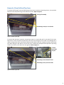
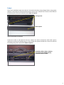
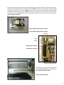
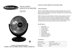
1
Heat Surge Model X5C Fire Place Insert Service Manual
Applies to all units w/30000208 circuit board
©2012 HS M4417A BR16597R-1
HEAT SURGE 8000 FREEDOM AVE, N. CANTON, OH 44720
330-244-8161
WWW.HEATSURGE.COM
1
Preface
This manual is intended for the servicing of the Heat Surge Model X5C fireplace insert. Only authorized
trained technicians should use this manual and perform the service needed. Risk of electrical shock,
burn and fire is present when performing service to the insert. The following tools are needed:
Multi-meter
Voltage sensor
Flat head screwdriver
Phillips head screwdriver
Needle nose pliers
Side cutters
Flashlight
Well lighted work area with 120vac switchable source
Specifications
Model X5C Electric Fireplace Insert
120v/60Hz, 15A, 1500W
Quantity 2 clear candelabra bulbs with E-12 (small) sockets, 120vac, 40W, 60HZ
Quantity 1 flame tube motor, 120vac, 40ma, 3.7W, 60HZ
Quantity 1 blower motor, 120vac, 60HZ
Quantity 2 heater elements, 120vac, 750W
Dimensions 24"W x 21"H x 10"D
2
Table of Contents
Description
Page
Removal of front grill and top cover
4
Incoming Power
5
Lamps
6
Flame Tube
8
Blower Assembly
10
Dual Element Heater with Fusible Link
13
Touch Pad Control
17
Temperature Pot and Temperature Sensor
18
Remote Control and Remote Control Sensor
19
Log removal and replacement
20
Electrical Drawing
21
3
Removal of Front Grill and Top Cover
To remove the front grill, remove 120vac power from insert, locate the 4 mounting screws, 2 on each side.
Remove screws and pull front grill out towards the front. Refer to Figure 1.
Front grill assembly
4 mounting screws, 2 on each side
Figure 1, removal of front grill
To remove the top cover, locate the 9 mounting screws, 2 on each side and 5 in the back of the insert.
Remove the screws and pull forward while at the same time lifting out. Be careful to not damage the 2
cables running to the main control board. Remove both cables from their respective sockets and remove
top. When laying the top down to service the insert, insolate the touchpad and temperature pot being
careful not to short out to the insert case ground. Refer to Figure 2.
2 cables,
touch pad
and pot
5 mounting screws located in rear
4 mounting screws, 2 on each side
Figure 2, removal of top cover
4
Incoming Power
The incoming power to the insert is 120vac/60Hz and will draw 15amps when running both heater
elements at a total of 1500watts. The incoming power, L1, is protected by a circuit breaker located on
the back of the insert. Also the insert is protected by a normally closed tip switch in series with the circuit
breaker located inside the top left hand side compartment. To reach this switch the top front grill and the
top cover must be removed. The hot lead, L1, is landed on terminal AC-L3 on the main control board. Refer
to Figure 4. The common, L2, is landed on terminal AC-N4 on the main control board. When the insert is
plugged into an 120vac source there should be 120vac between terminals AC-L3 and AC-N4 on the main
control board. If not, inspect plug and plug wire for damage. Also check to make sure the 120vac source is
not shut off by either a circuit breaker and/or switch controlling the 120vac source. The ground is landed
to the case. Refer to Figure 3.
Circuit Breaker
Main Control Board
Tip Switch
Figure 3, Main control board location
AC-N1 AC-N2
AC-N3
AC-N4
AC-L3
AC-L2
AC-L1
750W
750W
FLAME
FAN
LAMP
Figure 4, Main control board terminal locations
5
Lamps
There are 2 candelabra lamps each with an E-12 (small) socket base rating voltage 120vac, rating power
40watts. These lamps are located inside the bottom of the insert. Unfasten the 2 screws on the 2 sides of
the bottom panel, take out the bottom panel. Refer to Figure 5.
2 Fixing Screw
Bottom panel
Figure 5, bottom panel screw locations
Locate the 2 bulbs in the bottom of the unit. Examine the bulbs to determine which bulb requires
replacement. Remove the holding spring on the old bulb and replace the bulb with a new one. Reinstall
the holding spring after replacement. Refer to Figure 6.
Candelabra bulbs, 120vac, 40watts,
E-12 small socket. Holding spring
located around each bulb.
Figure 6, lamp locations
6
If bulbs refuse to light, check the 2 conductor plug for connection. To examine the plug the front glass
must be removed. Locate the 6 mounting screws, 3 on each side, remove all 6 and lift off front glass. Next
remove the 3 top screws holding the flame screen; the plug is located on the right hand side. The plug will
have a yellow and a white wire on one side and a black and white wire leading to the sockets. Check for
good connection. Refer to Figure 7.
Front glass mounting screws, quantity 6.
Flame screen mounting screws, quantity 3.
Figure 7, lamp plug location
If the plug connection is good, check for voltage between terminals LAMP and AC-N1 on the main control
board, (60vac to 120vac depending flame brightness set point). Refer to Figure 3 and Figure 4, for board
and terminal locations, if there isn’t any voltage present, the main control board is defective, replace with
a new board.
Repair connection,
plug in Lamps.
7
Flame Tube
The flame tube assembly consists of the flame tube, flame tube motor and mounting brackets. If there
isn’t any rolling frame the following needs performed. To access the flame tube assembly the front glass
must be removed and the flame screen pulled forward. Refer to Figure 9. Look for any jams that may
cause interference of the rotating tube. Next, inspect for the mounting of the flame tube. Make sure the 2
fasteners are present which hold the flame tube in its place. Also check for bent brackets which may have
caused the flame tube to fall out. Refer to Figure 8.
Flame tube fasteners quantity 2.
Flame tube motor.
Flame tube brackets, quantity 2.
Figure 8
If there isn’t any interference then inspect the flame tube motor. The flame tube is rotated by a 120vac,
60Hz motor drawing 40ma at 3.7watts which is plugged in, located in the same location as the lamp plug.
The plug will have a brown and a white wire on one side and a black and black wire leading to the motor.
Check for good connection. Refer to Figure 9.
Figure 9
8
If the plug connection is good, check for 110vac between terminals FLAME and AC-N1 on the main control
board, refer to Figure 1 and Figure 2 for board and terminal locations, if there isn’t any 110vac present the
main control board is defective, replace with a new board. If there is 110vac replace the flame motor.
Repair connection
and plug in.
9
Blower Assembly
The front grill and top of the insert must be removed to service the blower assembly. Refer to Figure 1 and
Figure 2. Lift the top off but leave the touch pad and temperature pot plugged in, be careful not to short
circuit against the insert casing. Rest the top on the casing so that the touch keypad points straight up.
Insolate the touch keypad from the casing with cardboard. With 120vac cord plugged in, turn the insert
on via the touch keypad. Next select low on the touch keypad, the blower should start running. If it
doesn’t slightly tap the blower with a screw driver, if unit starts then the problem is a sticky blower. If
the blower doesn’t start, take a voltage reading from the main control board. There should be 120vac
between terminal FAN and AC-N2. Refer to Figure 11. If there isn’t 120vac present then the main control
board is defective, replace with a new board.
Blower
Blower Motor
2 stage infrared heating elements
Fusible link
Heat discharge vent
Figure 10, Blower/Heater assembly
If the problem is a sticky blower, the blower must be replaced.
First with power removed, remove the heat discharge vent from
the insert. There are 4 screws, 2 located on each side, remove
all 4 and lift straight off. Next remove all wiring associated
with the blower motor, heat element and fusible link. The
blower motor has 2 black wires which are landed on terminals
FAN and AC-N2 of the main control board. Remove these.
Refer to Figure 11.
AC-N2
FAN
Figure 11, blower motor terminals
10
Next the dual heating element has 3 wires associated with it, 2 black and 1 white. The 2 black leads are the
120vac power leads landing on terminals both marked 750W on the main control board. The lower heating
element terminal lands on the lower 750W terminal on the main control board and the upper heating
element terminal lands on the upper 750W terminal on the main control board. The white common wire
is landed on terminal AC-N3 on the main control board, remove all 3 wires from main control board.
Refer to Figures 12 and 13.
Upper 750W heating element terminal
Lower 750W heating element terminal
Figure 12
AC-N3
AC-L2
AC-L1
750W, (upper terminal)
750W, (lower terminal)
Figure 13, dual element heat and
fusible link terminal locations.
Next remove the 2 blue fusible link leads from
terminals AC-L2 and AC-L1 from the main control
board. Refer to Figures 13 and 14.
Fusible link and blue leads
Figure 14, fusible link location
11
Remove the 4 screws, 2 on each side, holding the blower/heater assembly to the insert. Remove the
4 screws and lift blower/heater assembly off of the insert. Next locate the 4 screws, 2 on each side,
attaching the dual element heater to the blower. Remove these screws and remove dual element heater
from blower. Refer to Figure 15.
Screws holding dual element heater to blower.
Figure 15
Replace blower and reverse above procedure to assemble.
12
Dual Element Heater with Fusible Link
The front grill and top of the insert must be removed to service the heater assembly. Refer to Figure 1 and
Figure 2. Lift the top off but leave the touch pad and temperature pot plugged in, be careful not to short
circuit against the insert casing. Rest the top on the casing so that the touch keypad points straight up.
Insolate the touch keypad from the casing with cardboard. With 120vac cord plugged in, temperature pot
turned to “HI”, turn the insert on via the touch keypad. Next select low on the touch keypad, the blower
should start running and 10 seconds later the low heat should start; you will hear the contacts clicking of
the control relay on the main control board. If low heat does not come on, check for 120vac at the fusible
link. Place common test lead on the common terminal of the dual element heater marked “A” and the hot
test lead on the right hand terminal of the fusible link marked “B”. Refer to Figure 16.
Common location “A”
Left hand side of fusible link location “C”
Right hand side of fusible link location ”B”
Figure 16, fusible link
If 120vac is present, place the hot test lead to the left hand side of the fusible link marked “C” with the
common in the same location. Refer to Figure 16. If 120vac is not present let the unit cool down in order
to clear the fusible link. Wait 5 minutes and repeat test. When after repeating the test and there isn’t any
120vac present then check for 120vac present between the 750W (lower terminal) and AC-N3 on the
main control board. Refer to Figure 17.
AC-N3
750W (lower terminal)
Figure 17
13
If 120vac is not present then replace the main control board. If 120vac is present then the fusible link is
defective, replace the dual element/fusible heater.
Next select low on the touch keypad, the blower should start running and 10 seconds later the low heat
should start; you will hear the contacts clicking of the control relay on the main control board. Select high
heat and you will hear the contacts clicking of the control relay on the main control board. If the clicking
is not heard, repeat the above test only for high heat. Check for 120vac between terminals 750W (upper
terminal) and AC-N3. If 120vac is not present change out main control board. Refer to Figure 18.
AC-N3
750W (upper terminal)
Figure 18, high heat 120vac
In order to change out the dual element heater, remove blower assembly as described in section “Blower
Assembly”. Remove the 4 mounting screws, 2 on each side of the dual element heater. Refer to Figure 19.
Remove and replace with new heater assembly. Install blower assembly.
Screws holding dual element heater to blower.
Figure 19
14
15
16
Touch Pad Control
With the insert sitting up-right, plug the insert into a known good 120vac source. The insert will beep
once. Turn the insert on, the lights will light up and there will be a rolling flame. If the insert doesn’t beep
or the flame and lights turn on instantly or not at all, the touch keypad is defective. Check for ribbon cable
leads coming unplugged from both ends. Check to make sure there is a good connection at the main
control board socket. Refer to Figures 20 and 21.
Thermocouple plug location
Temperature low to high pot plug location
Remote control sensor plug location
Touch keypad plug location
Figure 20, plug locations defined on main control board
Figure 21, example of ribbon cable coming unplugged from touch pad connector
17
Temperature Pot and Temperature Sensor
With the insert sitting up-right, plug the insert into a known good 120vac source. The insert will beep once.
Turn the insert on, the lights will light up and there will be a rolling flame. Turn on the low heat. The blower
will turn on and 10 seconds later the low heat will come on. If it doesn’t, make sure the temperature pot is
turned to the “HI” setting. If low heat doesn’t come on check to make sure the temperature pot is plugged
into the main control board. Refer to Figure 20 for location. Also check to see if there is a good connection
at the temperature pot. Refer to Figure 22.
Figure 22, example of bad connection at temperature pot
Check the integrity of the temperature sensor located just behind the main control board. Refer to
Figure 23. Check to make sure the sensor is plugged into the main control board. Refer to Figure 20. If
there is a problem, the insert will still heat but without the use of the temperature room setting. If all
checks out, refer to section “Dual Element Heater and Fusible Link.”
Figure 23, temperature sensor location
18
Remote Control and Remote Control Sensor
The unit comes with a remote control complete with power on/off button, low/high heat selector and up/
down flame setting. Refer to Figure 24.
Flame up/down
Heat low/high
Power on/off
Figure 24, remote control description
If remote control refuses to work check battery orientation
and integrity. Refer to Figure 25.
Figure 25, battery location and orientation.
Also check that the remote control sensor, red plug socket, is plugged in properly into the main control
board. Refer to Figure 20. Lastly check the location and integrity of the remote control sensor located
behind the flame screen. Refer to Figure 26.
Figure 26, remote control sensor
19
Log removal and replacement
The front glass needs to be removed. Locate the 6 screws, 3 on each side, holding the front glass frame in
and remove. Refer to Figure 27.
Locate 6 screws, 3 on each side
Figure 27
Locate the 4 black rubber plugs, 2 on each side of the insert. Remove rubber plugs and remove the 4
screws holding the log set in the insert. Pull the log set straight out towards the front. Reverse above to
install new log set. Refer to Figure 28.
Rubber plugs with mounting screws,
quantity 4, 2 on each side of insert.
Figure 28
20
Electrical Drawing
21