1
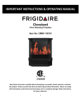
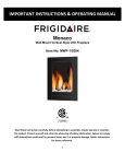
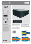
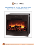
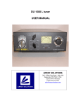
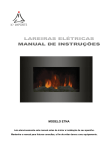
Automatic Voltage Stabilizer
Precautions
1. Place the Automatic Voltage Stabilizer(AVR) in a dry area. Keep it away from corrosive
chemicals,flammable gases, conductive dust, steam and out of reach by the children.
2. The Grounding Terminal wire and Neutral Terminal wire should be properly connected to
ensure safety. Improper connection can cause short circuit and may damage the unit.
3. During normal operation, the AVRs will produce heat. Please ensure proper ventilation by
not blocking the vents on the unit.
4. It is normal to hear friction sounds when fluctuation of voltage occurs. At this point,the
AVR is regulating the voltage.
5. Do not open the unit when it is connected to the power source(Live outlet).
6. When the unit has been used for a long period of time, the unit should have regular
maintenance by cleaning the inside portion, especially between the carbon and the coil by
a qualified electrical technician for efficient operation. If the carbon brush is already worn
out, replace it immediately so that it will not cause serious or further damage to the unit.
Instruction Manual
AUTOMATIC VOLTAGE STABILIZER
7. Do no continue to use the unit if its not working properly, instead bring it to an authorized
service certer or qualified electrical technician.
8. If there are parts that were replaced or the unit was opened/repaired not by an authorized
serivce representative, we will not be liable to an quality and safety problems.
9. Tampering with the AVR unit voids the warranty. This includes repares, replacement of parts
or modifications done to the unit by unauthorized service centers. The company will not be
held liable for any damages arising from the product due to its misuse or abuse.
Before operating this product, please read this manual first and preserver it well.
Automatic Voltage Stabilizer
Automatic Voltage Stabilizer
Introduction
3. LCD/LED DISPLAY;
Modern appearance by equipping with LCD/LED display meters.
The voltage stabilizers are designed according to international design principles. It is
noted for its visible advantages, such as elegant apperance, compact design, light weight,
high efficiency, no distortion of output waveform, complete protection functions and etc.
All the voltage stabilizers have passed strict quality inspections to maintain top and best
quality electronic elements.
The voltage stabilizers are suitable for the areas where voltage fluctuates frequently in
power grid.
The voltage stabilizers are widely applied and suitable to use for industrial companies,
schools, medical and scientific research laboratories, communication central offices and
household appliances with high power load.
4. Provide BYPASS function:
All of the Models are produced with BYPASS function.
5. Overload or short-circuit protection:Single Phase 1.5KVA and below models offer fuse
to protect against overload or short circuit; and other specification models use circuitbreaker.
6. Technical Specifications
ITEM
MODELS
Input Voltage
Range
SINGLE PHASE
THREE PHASE
500VA; 1000VA; 1500VA; 2000VA;
2500VA; 3000VA; 5KVA; 7.5KVA;
10KVA; 15KVA; 20KVA; 30KVA;
45KVA
Single phase three-wire system
150~270V
Single phase three-wire system
Output Voltage
Technical Characteristics
1. Output capability
When main voltage is lower than 198V, the output capacity of this equipment reduces correspondingly; the relationship between output capability and input voltage is shown as
diagram 1
2. Overload capability
When input voltage of this equipment changes from 198V to 270V, its overload capability is
shown as table 1 under emergency service
(P---Output capability; Pc---Rated output capability; U---Input voltage )
Output 246+/-4V
Phase voltage:246+/-4V
(Phase voltage as reference)
Under-voltage
protection value
Output 184+/-4V
Phase voltage:184+/-4V
(Phase voltage as reference)
Volt.stabilizing
Accuracy
Waveform distortion
Load power factor
Efficiency
Output 220V
Adjustable time
Delay time
Electric strength
150
Insulation resistance
270
Diagram 1
Table 1
Three phase five-wire system
Phase voltage: 150~270V
Line voltage: 260~465V
Three phase five-wire system
Phase voltage: 220V
Line voltage: 380V
Over-voltage
protection value
Frequency
Overload Overload time not
permitted(min.)
ratio
220V
1.5KVA; 3KVA; 4.5KVA;
6KVA; 9KVA;15KVA; 20KVA;
30KVA; 45KVA; 50KVA;
60KVA; 80KVA;90KVA
+/-3%
50~60Hz
No additional wavefor distortion
0.8
>90%
<1s when input voltage has a change of 10%
Long time delay:5+/-2min; Short time delay: 5+/-2s
No flashover or breakdown when it withstands 1500V/min.
2M
Automatic Voltage Stabilizer
Automatic Voltage Stabilizer
7. Applicable working conditions
Environment temperature: -5~40
Relative humidity: less than 95%
Air pressure: 86~106kPa
Working environment: no chemical deposition, scales, harmful corrosive medium as
well as flammable or explosive gas. Besides, the altitude is not higher than 1,000m.
Working Principle
Sampling
control circuit
Sampling
control circuit
1. Circuit diagram(see diagram 2~diagram 6)
2. Sampling control principle(see diagram 7)
(Note: following diagrams are only for reference, if they are changed partially for improving
product, we will not notice separately)
Sampling
control circuit
Change-over switch for output line voltage
Diagram 4: Circuit diagram of SVC series three phase 1.5KVA~30KVA models
Sampling
Control circuit
Diagram 2: Circuit diagram of SVC series single phase 0.5KVA~10KVA models
Sampling
control circuit
Sampling
control circuit
Sampling
Control circuit
Sampling
control circuit
Change-over switch for output line voltage
Diagram 3: Circuit diagram of SVC series single phase 10KVA and above models
Diagram 5: Circuit diagram of SVC series three phase 15KVA and above models
Automatic Voltage Stabilizer
Automatic Voltage Stabilizer
Input 150-270V
Diagram 8: Wiring diagram of three phase 5KVA and above models
Earth terminal(Note)
Input line voltage 260~465V
Output line voltage 380V
Note: If this earth terminal is not mounted on the terminal block, please connect the wire according to
mark
in the machine.
Diagram 9: Wiring diagram of three phase 1.5KVA and above models
Operating instruction
1. Read the instruction manual carefully before using the unit.
2. Before operating AVR units with capacity of 2000watts and above, connect the wires
according to the symbol in front and back panel of the unit. Make sure the wires are
properly connected to the terminal. Make sure the power source is within the range of the
input voltage of the unit.For higher wattages capacity you may refer to the diagram 9 for
the correct wiring diagram.
For the AVR units with capacity of 1500watts and below, power cords and plugs are already
provided.
(Please follow labeled voltage for output terminals for proper usage).
3. AVR unit should be placed in a dry and well ventilated area before using.
When the AVR unit is switched on, it will automaticaly regulate the input voltage.
If the meter on the unit shows 220V(380V for the three phase AVR), the unit is ready and
appliances plugged into the AVR may now be used.
4. Total load(watts) should not exceed the rated capacity of the AVR unit
to avoid overloading.
5. For appliances with inductive load(such as air conditioner, refrigerator, industrial fans etc.),
It is recommended to use an AVR that has a rated power capacity of 3~5 times of the load
power, because the start up current of these appliances are very high.
For capacitive load, just leave enough allowance on the rated power capacity of the unit and
avoid overloading.
6. You man check your appliances for the rated power consumption to avoid overloading the
AVR unit.
7. Make sure that the appliances are switched OFF before turning ON the AVR unit.
8. When power failure occurs or the input voltage is too high, turn OFF the AVR immediately.