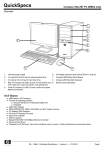
1
KERN & Sohn GmbH
GB
Ziegelei 1
Tel: 0049-[0]7433- 9933-0
D-72336 Balingen-Frommern
Fax: 0049-[0]7433-9933-149
E-Mail: [email protected]
Internet: www.kern-sohn.com
Service Manual
Analytical Balances
Page 2
KERN ABS/ABJ
Version 2.1
ABS/ABJ-SH-e-0921
GB
KERN ABS/ABJ
Version 2.1
Service Manual
Analytical Balances
Basic Information
Grundlegende Hinweise
The device must be repaired only by trained specialist staff or personnel with
professional formation (such as a repair-specialist accredited by law concerning
verification).
The service manual is obligatory for repair work.
After repair, original conditions of the device have to be restored.
Only original spare parts should be used.
Instructions about conformity-evaluated scales:
Repair must be carried only at 100% compliance with the type approval.
A violation of this specification will result in a loss of the type approval!
After successful repair the balance will have to be reverified before it can be used
again in a statutorily regulated field.
Das Gerät darf nur von geschultem oder beruflich ausgebildetem
Fachpersonal (z. B. eichrechtlich anerkannter Instandsetzer) repariert werden.
Die Serviceanleitung ist bindend für Reparaturen.
Das Gerät muss nach erfolgter Reparatur wieder in den Originalzustand
zurückversetzt werden.
Es dürfen nur Originalersatzteile verwendet werden.
Hinweis zu konformitätsbewerteten Waagen:
Reparatur darf nur in 100% -iger Übereinstimmung mit der
Bauartzulassung erfolgen. Ein Verstoß gegen diese Vorgabe führt zum Erlöschen der
Bauartzulassung!
Nach erfolgreicher Reparatur muss eine Nacheichung erfolgen, um die Waage
wieder im gesetzlich geregelten Bereich verwenden zu können.
-2-
ABS/ABJ-SH-e-0921
Contents
1.
SERVICE MENU.......................................................................................................... 6
1.1
How to enter the service menu mode......................................................................... 7
1.2
Contents of the service menu mode........................................................................... 8
1.2.1
Model name...................................................................................................... 8
1.2.2
Unloading the built-in weight .......................................................................... 8
1.2.3
Loading/Unloading the built-in weight ............................................................ 8
1.2.4
Linear adjustment ............................................................................................. 8
1.2.5
Inputting the weight values for linear adjustment............................................ 8
1.2.6
Software version No......................................................................................... 9
1.2.7
Print out the non-volatile RAM data ................................................................ 9
1.2.8
Inputting the external weight value used for the calibration of the built-in
weight value. .................................................................................................... 9
1.2.9
Calibration of the built-in weight value ........................................................... 9
1.2.10
Editing the non-volatile RAM data .................................................................. 10
2.
HOW TO INSPECT THE UNIT ASSY...................................................................... 11
3.
INSPECTION/REPLACEMENT OF THE FULCRUM SPRING,
LOAD SPRING, AND PARALLEL GUIDE ............................................................. 13
4.
3.1
How to dismount the unit assy................................................................................... 13
3.2
Inspection and replacement of the fulcrum spring, load spring, and parallel guide....... 13
PART REPLACEMENT.............................................................................................. 17
4.1
Replacement of the power board assy ....................................................................... 17
4.2
Replacement of the digital board assy ....................................................................... 17
4.3
Replacement of the analog board assy....................................................................... 17
4.4
Replacement of the detector assy............................................................................... 18
4.5
Replacement of the switch panel ............................................................................... 18
-3-
ABS/ABJ-SH-e-0921
5.
ASSEMBLING THE CASE ASSY ............................................................................ 19
6.
BALANCE ADJUSTMENT ........................................................................................ 20
6.1
Adjustment procedure of the balance ........................................................................ 20
6.2
How to turn ON the power while avoiding automatic span calibration
(With ABJ series only) .............................................................................................. 21
6.3
Height adjustment of the detector ASSY................................................................... 21
6.4
Adjustment of the shake protector ............................................................................. 21
6.5
Mechanical balance and level adjustment ................................................................. 22
6.6
Rough adjustment of the eccentric error.................................................................... 23
6.7
Adjustment of the built-in weight loader mechanism
(With the ABJ series only)......................................................................................... 23
6.8
Fine adjustment of eccentric error ............................................................................. 24
6.9
Linearity adjustment .................................................................................................. 25
6.10
Setting the ERROR CHECK ON/OFF ...................................................................... 25
7.
PERFORMANCE CHECK OF THE BALANCE ..................................................... 26
7.1
Environment and conditions for checking the balance.............................................. 26
7.2
Repeatability check.................................................................................................... 26
7.3
Eccentric error check ................................................................................................. 27
7.4
Linearity inspection ................................................................................................... 27
8.
PART LIST.................................................................................................................... 30
9.
TROUBLESHOOTING................................................................................................ 34
9.1
List of troubles ........................................................................................................... 34
9.2
Countermeasures for each trouble ............................................................................. 34
9.2.1
“CAL E2” ......................................................................................................... 34
9.2.2
“CAL E3” ......................................................................................................... 35
9.2.3
“CAL E4” ......................................................................................................... 36
9.2.4
“CAL d” ........................................................................................................... 36
9.2.5
“Err 01” ............................................................................................................ 37
9.2.6
“Err 04” ............................................................................................................ 37
9.2.7
“Err 05” ............................................................................................................ 37
-4-
ABS/ABJ-SH-e-0921
9.2.8
Span calibration (CAL) time is long. ............................................................... 37
9.2.9
Display is abnormal.......................................................................................... 38
9.2.10
The span points disperse whenever span calibration by using the built-in
weight is performed.......................................................................................... 38
9.2.11
“A CAL” appears frequently............................................................................ 38
9.2.12
The display deviates after stability mark (→) appears..................................... 39
9.2.13
Some sound is heard from the balance............................................................. 39
9.2.14
Nothing appears on the display ........................................................................ 40
9.2.15
The switches on the front panel do not work ................................................... 40
9.2.16
The display becomes unstable when something is loaded on the pan ............. 40
9.2.17
Dispersion, fluctuation, zero drift, and poor return of zero point .................... 41
9.3
Checkpoints ............................................................................................................... 41
9.3.1
Detector assy position ...................................................................................... 41
9.3.2
Leak and disconnection of the coil assy........................................................... 41
9.3.3
Display when the power is turned ON ............................................................. 41
9.3.4
Temperature sensor signal check ..................................................................... 42
9.3.5
Dispersion of span calibration.......................................................................... 43
9.3.6
Dispersion, fluctuation, zero drift, and poor return of zero point .................... 43
10. PRINCIPLE OF MEASUREMENT............................................................................ 45
10.1
Magnet coil current value .......................................................................................... 45
10.2
Temperature correction of the current value of electromagnetic coil........................ 45
10.2.1
Temperature correction by the electric circuit ................................................. 45
10.2.2
Temperature correction by software ................................................................ 45
10.3
Linearity correction ................................................................................................... 46
10.4
Span calibration ......................................................................................................... 46
-5-
ABS/ABJ-SH-e-0921
1.
SERVICE MENU
1.1
How to enter the service menu mode
First, let the balance display the weight value.
(1) Hold down both the [ON/OFF] key and PRINT key simultaneously for three
(2)
seconds or longer.
Release both the [ON/OFF] key and PRINT key at the same time.
(3)
Hold down both the CAL/MENU key and UNIT key simultaneously until the
model name is displayed on the LCD.
ABS has now entered the service menu.
ABJ:
(4) Display for inputting password is shown.
(5) Input the password using UNIT key and PRINT key.
The password is
"P___321".UNIT key increases the figure by one and UNIT key moves
the digit to the upper. And PRINT key moves the blinking digit to right.
(6) When the password is set, press TARE key.
(7) Version No. and the model code are displayed and the balance enters into the
service menu.
ABJ has now entered the service menu.
NOTE (ONLY ABJ) :
Adjustment log counter(ECTA model)
Note: Adjustment log counter
purpose: To secure components that may
not be dismantled or adjusted by the user
Adjustment log counter works when LIN-ADJ and LIN-SET in service menu are
chosen. The indication of log counter is displayed at the time of the power on.
Example: A01- 3.00
A01: adjustment log counter *,
01 increment when enter LIN-SET, LIN-ADJ
3.00: application software version number
-6-
ABS/ABJ-SH-e-0921
* The number that it is written in label* and LCD displayed number must
correspond.
Label*: It is put on right side of balance. That is shown
temperature range etc.
1.2
Contents of the service menu mode
Contents of the service menu are as follows:
Display
LCD
on
E.AbS22
w.int
w.SEt
t-SPAn
Lin-Adj
Lin-SEt
1.00-1.02
--End-EE oUt
i CAL
CAL SEt
PCAL.SEt
PCAL
-wAd-
-tAd-oAd-
the Menu contents
Model name
Unloading
the
built
-in
weight
after
loading/unloading it
Loading/unloading the built-in weight
Aging
Linear adjustment
Inputting the weight values for linear
adjustment
Software version No.
End of service menu (Returns to the weight
display mode.)
Printing out the non-volatile RAM data
(A printer dedicated for the balance is required.)
Span adjustment by the built-in weight (with the
ABJ series only)
Inputting the external weight value used for
span calibration
Inputting the external weight value used for the
calibration of the built-in weight value
Calibration of the built-in weight value (Do not
select this when you are using the ABS series.)
A/D value of the load
(Approx. 800,000 to 1,000,000 counts without
any load on the weighing pan (1*): About 2.5
counts/0.1 mg)
A/D value of the temperature (15,000 to 17,000
counts at the temperature around 25°C)
AD value of the load after temperature
correction (unit: g) (The balance is normal when
the zero point is approx. 1 g. When it is 10 g or
more, the balance might be out of order.)
-7-
ABS/ABJ-SH-e-0921
-LAd-wG-bAtS.id-Set
Edit
trAdE:on
trAdE:oF
-End-1.2.1
A/D value after temperature correction and
linear correction (unit: g)
Weight value
Power supply voltage (unit: V)
Inputting Serial No. (Last five digits only)
Editing non-volatile RAM data
Export specification setting (If set to Export
specification, “E” is attached to the left of the
model name
Domestic specification setting
End of service menu (Returns to the weight
display mode.)
Model name
Displays the model name and the Domestic/Export setting condition.
“
AbS22” -
“E.AbS22”-
1.2.2
AbS 220 for Domestic specification setting
AbS 220 for Export specification setting
Unloading the built-in weight
By selecting “w.int”, the balance will unload the built-in weight.
1.2.3
Loading/Unloading the built-in weight
By selecting “w.SEt”, the operational phase of the built-in weight to the balance
proceeds by one step. ((1)→(2)→(3)→(1))
1.2.4
(1)
the phase with the built-in weight unloaded.
(2)
the phase with the built-in weight loaded.
(3)
the phase with the built-in weight incompletely loaded.
Linear adjustment
Linear adjustment can be executed by selecting “Lin-Adj”. (See 6.9 Linearity
adjustment.)
1.2.5
Inputting the weight values for linear adjustment
The weight values for linear adjustment can be input by selecting “Lin-SEt.” (See
6.9 Linearity adjustment.)
Input the true weight values of the following weights.
for the balance with the maximum capacity of 320g:
50g, 100g, 150g, 200g, 230g, 300g, 350g
for Others:
50g, 100g, 150g, 200g, 230g
-8-
ABS/ABJ-SH-e-0921
How to input:
Pressing the UNIT key increases the numeral value at the
blinking digit by one.
Pressing the PRINT key moves the digit by one.
To validate the input value, press the TARE key.
"SEt" will be displayed for several sec to inform you that the
input has been validated.
1.2.6
Software version No.
Displays the software versions of the control CPU and the operational CPU.
“1. 00 - 1. 02”:
The number in the left indicates the software version No. of the
control CPU and the one in the right indicates that of the
operational CPU.
1.2.7
Print out the non-volatile RAM data
By selecting “EE oUt”, non-volatile RAM data is output to the balance (EP-50 or
EP-60A) connected.
1.2.8
Inputting the external weight value used for the calibration of the built-in weight
value.
By selecting “PCAL.SEt”, the external weight value for calibration of built-in
weight value can be input. Input the true value of the external weight for the
calibration of built-in weight value.
How to input:
Pressing the UNIT key increases the numeral at the blinking
digit.
Pressing the PRINT key moves the digit by one.
To validate the input value, press the TARE key.
"SEt" will be displayed for several sec to inform you that the
input has been validated.
1.2.9
Calibration of the built-in weight value
With the ABJ series, the built-in weight value can be calibrated by using the
external weight(s).
Never execute this menu (function) with the ABS series balance.
How to calibrate the built-in weight value:
(1)
Select “PCAL” in the service menu.
(2)
First, the balance checks the zero point.
-9-
ABS/ABJ-SH-e-0921
(3)
Load the external weight on weighing pan (1*) as the already set external
weight value blinks on the LCD .
(4)
As “0. 0000 g” blinks after almost 10 sec, unload the external weight from
weighing pan (1*).
While “PCAL 1” is displayed, the balance measures the built-in weight.
While “PCAL 0” is displayed, the balance measures 0 point.
After span calibration by the built-in weight is executed, the balance displays
the weighing value.
1.2.10
Editing the non-volatile RAM data
By selecting “Edit”, the following display appears and the non-volatile RAM data
can be edited.
[Example of display]
00 : 0123
Data is indicated by two bytes.
Address
Meaning of the above display: 01 H is written at Address 00.
23 H is written at Address 01.
How to edit
• Pressing the CAL/MENU key increments the address by one.
•
Pressing the UNIT key increases the numerical value of the blinking digit by
•
one.
Pressing the PRINT key moves the digit.
•
Pressing the TARE key validates the data of the displayed address.
- 10 -
ABS/ABJ-SH-e-0921
2.
HOW TO INSPECT THE UNIT ASSY
<Disassembly and Inspection>
(1)
Pull out the power cable and remove weighing pan (1*), draft shield ring (2*), and pan
supporter assy (3*). (See Fig. 1 on page 47.)
(2)
Remove the case assy. (See Fig. 1 on page 47.)
(2-1)
Remove three screws (Semus M4 × 10) and dismount the case assy from the base.
(2-2)
Pull out the operation cable from digital board assy (19*). Be careful not to damage
the cable in this occasion.
(3)
Remove the analog board cover and the inner case. (See Fig. 4 on page 49.)
(3-1)
Remove two screws (Semus M3 × 6) and dismount the analog board cover.
(3-2)
Pull out the detector output cable and the coil current cable from analog board assy
(20*).
(3-3)
Remove two screws (Semus M4 x 8) and remove the inner case.
Checkpoint 1:
Check that the shake protector and the lever pin do not make
contact and no dust exists between them. (See 6.4)
Checkpoint 2:
Check the soldering of Pt-Ni band (15*) and check that coil assy
(25*) is not disconnected. (See Fig. 9 on page 54.)
(4)
Remove the weight holder and the built-in weight. (With the ABJ series only)
Remove two screws (Semus M3 × 8) and dismount the weight holder and built-in
weight. (See Fig. 7 on page 50.)
Checkpoint 3:
(5)
Check that no dust adhere to the built-in weight.
Note:
Keep the weight holder and the built-in weight away from dirt and/or dust.
Note:
Do not lose rubber washers (27*).
Remove the magnet cover. (See Fig. 2-1 on page 48.)
Remove four screws (pan head screw M2.5 × 6) and dismount the magnet cover.
Note:
Keep the magnet assy away from dust.
Checkpoint 4:
Check that coil assy (25*) makes no contact with the magnet assy
and no dust exist between them. (See Fig. 2-2 on page 48.)
•
When they are in contact, loosen the tightening screws of the lever and coil assy
(25*) to adjust the position of coil assy (25*).
•
If any dust exits, clean coil assy (25*) and the magnet assy as follows.
How to clean coil assy (25*) and the magnet assy:
- 11 -
ABS/ABJ-SH-e-0921
Remove the unit assy from the base. (Refer to Fig. 8 on page 53.)
Remove the magnet cover, then the magnet assy from the unit assy. (Refer to Fig. 2-3
on page 48.)
Clean coil assy (25*) and the magnet assy, taking the dust away from them by using
scotch tape.
(6)
Note:
Keep the unit away from dust.
Note:
Do not hold the error adjustment lever. (Refer to Fig. 8 on page 53.)
Inspection of fulcrum spring (13*), load spring (14*), and parallel guide (37*).
Inspect fulcrum spring (13*), load spring (14*), and parallel guide (37*) according to “3.
INSPECTION AND REPLACEMENT OF FULCRUM SPRING, LOAD SPRING
AND PARALELL GUIDE.”
<Reassembly>
(7)
Assemble the magnet cover (4 pcs.) using four screws (pan head screw M2.5 × 6.) (See
Fig. 2-1 on page 48.)
(8)
Mount the built-in weight and the weight holder. (See Fig. 7 on page 50.)
Note:
Do not mount the weight holder at the wrong direction and do not mount the
rubber washer(s) (27*) at the wrong position.
(9)
(10)
Adjust the built-in weight loader mechanism. (See 6.7.)
Mount the inner case and the analog board cover. (See Fig. 4 on page 49.)
Note:
Do not pinch a cable between the base and the inner case.
(11)
Mount the case assy. (See Fig. 1 on page 47.)
(12)
Mount draft shield ring (2*), pan supporter assy (3*), and weighing pan (1*). (See Fig.
1 on page 47.)
(13)
Adjust the level of the balance, turn ON the power, and check the balance operation.
- 12 -
ABS/ABJ-SH-e-0921
3.
INSPECTION/REPLACEMENT OF THE FULCRUM SPRING, LOAD
SPRING, AND PARALLEL GUIDE
3.1
How to dismount the unit assy
(1)
Same as (1) in Section 2 “HOW TO INSPECT THE UNIT ASSY.”
(2)
Same as (2) in Section 2 “HOW TO INSPECT THE UNIT ASSY.”
(3)
Same as (3) in Section 2 “HOW TO INSPECT THE UNIT ASSY.”
(4)
Same as (4) in Section 2 “HOW TO INSPECT THE UNIT ASSY.”
(5)
Remove the unit assy from the base.
Remove four screws (Semus M4 × 25) and dismount the unit assy from the base.
(See Fig. 8 on page 53.)
Note:
Keep the unit assy away from dust.
Note:
Do not hold the eccentric error adjustment lever of the force cell frame. (See
Fig. 8 on page 53.)
Checkpoint:
Check that there is no strain, no crack, and/or no warp with upper
and lower parallel guides (37*). (See Fig. 15 on page 57.)
3.2
Inspection and replacement of the fulcrum spring, load spring, and
parallel guide
<Disassembly and Inspection>
Preparation: Disassemble and assemble the unit assy at a location free from dust.
Attention must be paid to prevent dust from entering the clearance
between parallel guide (37*) and the force cell frame, and the clearance
between the shake protector and the pins for lever.
(1)
Remove the blue and the yellow lines connected to the temperature sensor from
detector assy (21*) using a soldering iron. (See Fig. 10 on page 54.)
(2)
Remove Pt-Ni band (15*) using a soldering iron. Remove a screw (Semus M4 × 12)
to dismount the relay board from the force cell frame. (See Fig. 9 on page 54.)
(3)
Loosen the nut with a wrench and remove the screw bar to which balance weight
(33*) and eccentric weight (*28) are attached, from the lever.
Note:
Be sure to perform the work with a shake protector attached. (See Fig. 10 on
page 54) Otherwise, the spring might be damaged.
(4)
Remove two screws (M4 × 6) and dismount the shake protector from the force cell
frame. (Refer to Fig. 10 on page 54.)
Note:
Be careful not to bend fulcrum spring (13*) and load spring (14*).
- 13 -
ABS/ABJ-SH-e-0921
(5)
Mount assembling jig (22*) for the ABJ series to the unit assy. (See Fig. 13 on page
56.)
Note:
First, secure jig screw A1 tightly, and then insert A2 and A3 in this order.
Finally, tighten A2 and A3. To dismount the assembling jig, execute the
above procedure in reverse.
Replacing coil assy (25*):
By removing the magnet cover and the connection screw between the lever and coil
assy (25*), the coil assy can be replaced. (See Fig. 2-3 on page 48.)
(6)
Remove one screw (bolt with a hole, SPG washer, small flat washer) and dismount
the pan supporter assy. (See Fig. 15 on page 57.)
Checkpoint:
Check if there is any strain, crack, and/or warp with fulcrum spring
(13*) and load spring (14*).
(7)
Remove fulcrum spring (13*) and load spring (14*) with a hex wrench. (See Fig. 13
on page 56.)
Checkpoint:
Check if there is any strain, crack, and/or warp with fulcrum spring
(13*) and load spring (14*).
(8)
Remove four screws for parallel guide (36*) respectively and dismount upper and
lower parallel guides (37*). (See Fig. 15 on page 57.)
Note:
Do not lose the eccentric error adjustment spacer (34*) placed under parallel
guide (37*).
Note:
Do not forget the original location of the eccentric error adjustment spacer
(34*) as it must be mounted on that location when reassembled.
Checkpoint:
Check if there is any strain, crack, and/or warp with upper/lower
parallel guides (37*).
<Reassembly>
(9)
Assemble upper/lower parallel guides (37*). (See Fig. 15 on page 57.)
Note:
Align the mount hole of parallel guide (37*) and that of the force cell frame
at the center.
Note:
Place the eccentric error adjustment spacer between the upper portion of the
column and parallel guide (37*) where it was placed before, and then fix it
with a screw. (18 kgf•cm)
Note:
Do not use a used screw to fix parallel guide (36*).
- 14 -
ABS/ABJ-SH-e-0921
(10)
Assemble fulcrum spring (13*) and load spring (14*) with the following procedure.
(See Fig. 14 on page 56.)
(a)
Place each spring so that the mount holes of fulcrum spring (13*) and load spring
(14*), are aligned with the center of those of the unit assy.
(b)
Insert spring set pin (24*) into the upper hole and lightly tighten the lower bolt
ensuring that each spring will not move. (See Fig. 14-1 on page 15.)
Fig. 14-1
(c)
Tighten the lower bolt with 20 kg•cm ensuring that each spring will not move.
(d)
Tighten the upper screw with the torque free washer touching the end surface of
the lever to prevent the spring from rotating together. (Torque 20 kg•cm) (See Fig.
14-2 on page 15.)
Fig. 14-2
(e)
Check if each spring is not bent or cracked.
Note:
When replacing fulcrum spring (13*) and load spring (14*), replace three of
them together at one time.
Note:
Use the regular bolts, washers, and cup washers (26*) only.
Note:
Do not use a used cup washer (26*) again.
- 15 -
ABS/ABJ-SH-e-0921
(11)
Remove the magnet cover and after adjusting the position of coil assy (25*) (using a
screw), mount the magnet cover. (See Fig. 2-2 on page 48.)
(12)
(13)
Fix the pan supporter assy with screw. (See Fig. 15 on page 57.)
Note:
Tighten the screw with the torque of 25 kg•cm using a hex torque wrench.
Note:
Mount the pan supporter so that it is visually parallel to the lever.
Remove assembly jig for the ABJ series (22*) from the unit assy. (See Fig. 13 on
page 56.)
Note:
(14)
Remove jig screws A3, A2, and A1 in this order.
Incorporate the shake protector so that it does not make contact with the lever pin.
Checkpoint:
Make adjustment according to “6.4 Adjustment of the shake
protector.”
(15)
Mount the screw bar to which balance weight (33*) and eccentric weight (28*) are
attached to the lever. (See Fig. 12 on page 55.)
Checkpoint:
Make adjustment according to “6.5 Adjustment of mechanical
balance and level.”
(16)
Mount the relay board and solder Pt-Ni band (15*). (See Fig. 9 on page 54.)
(17)
Solder two temperature sensor lines to A and B of detector assy (21*).
Note:
Connect the yellow line to A and blue line to B.
- 16 -
ABS/ABJ-SH-e-0921
4.
PART REPLACEMENT
4.1
Replacement of the power board assy
(1)
Same as (1) in Section 2 “HOW TO CHECK THE UNIT ASSY.”
(2)
Same as (2) in Section 2 “HOW TO CHECK THE UNIT ASSY.” (See Fig. 5 on
page 51 for the following.)
(3)
Pull out the flat cable (26P) from power board assy (18*).
(4)
Remove two screws (hex screws) at the RS232C connector portion using a box
driver.
(5)
Remove three screws (Semus M3 × 8 and Semus M4 × 8) and dismount power board
assy (18*) from the base.
(6)
Set new power board assy (18*) and fix it to the base with three screws.
(7)
Tighten two screws (hex screws) at the RS232C connector portion.
(8)
Connect the flat cable (26P) to power board assy (18*).
Note:
4.2
The red line must be located in the left as viewed from the rear of the balance.
Replacement of the digital board assy
(1)
Same as (1) in Section 2 “HOW TO CHECK THE UNIT ASSY.”
(2)
Same as (2) in Section 2 “HOW TO CHECK THE UNIT ASSY.” (See Fig. 5 on
page 51 for the following.)
(3)
Pull out all the cables from digital board assy (19*).
(4)
Remove four screws (Semus M4 × 8) and dismount digital board assy (19*) from the
base.
(5)
Mount new digital board assy (19*) to the base with four screws (Semus M4 × 8).
(6)
Connect all the cables to digital board assy (19*).
4.3
Replacement of the analog board assy
(1)
Same as (1) in Section 2 “HOW TO CHECK THE UNIT ASSY.”
(2)
Same as (2) in Section 2 “HOW TO CHECK THE UNIT ASSY.” (See Fig. 4 on
page 49 for the following.)
(3)
Remove two screws (Semus M3 × 6) and dismount the analog board cover.
(4)
Pull out all the cables from analog board assy (20*).
(5)
Remove two screws (Semus M3 × 10) and dismount analog board assy (20*) from
the inner case.
Note: Do not lose the spacer nut (type 1 M4).
- 17 -
ABS/ABJ-SH-e-0921
(6)
Place the spacer nut (type 1 M4) between new analog board assy (20*) and the inner
case and fix it with two screws (Semus M3 × 10).
(7)
4.4
Connect all the cables and mount the analog board cover.
Replacement of the detector assy
(1)
Same as (1) in Section 2 “HOW TO CHECK THE UNIT ASSY.”
(2)
Same as (2) in Section 2 “HOW TO CHECK THE UNIT ASSY.” (See Fig. 4 on
page 49 for the following.)
(3)
Remove two screws (Semus M3 × 6) and dismount the analog board cover.
(4)
Pull out the detector output cable from analog board assy (20*).
(5)
Remove two screws (Semus M4 × 8) and dismount the inner case from the base.
(6)
Remove two screws (Semus M3 × 8) and dismount detector assy (21*).
(7)
Mount new detector assy (21*).
(8)
Connect the detector output cable.
(9)
Turn ON the power and adjust the height and the volume control of detector assy
(21*). See “6.3 Height Adjustment of the Detector Assy.”
(10)
Mount the inner case.
(11)
Mount the analog board cover.
4.5
Replacement of the switch panel
(See Fig. 6 on page 52 for the following.)
(1)
Remove switch panel (9*).
(2)
Wipe off dirt on the dented portion.
(3)
Paste new switch panel (9*).
- 18 -
ABS/ABJ-SH-e-0921
5.
ASSEMBLING THE CASE ASSY
(1)
Remove four screws (M4 × 6) and dismount the back plate. (See Fig. 16 on page 58.)
(2)
Remove pull (29*) and pull fixer (30*) from side glass assy (5* and 6*), and pull them
out from the case assy.
Note:
As it is bonded with double-faced tape, carefully remove them using a
precision driver.
Note:
Attention should be paid not to lose the flat spring as it is placed between side
glass assy (5* and 6*) and the case roof assy.
(3)
Remove two nuts and disassemble the case, the draft shield column, and the case roof
assy. (See Fig. 17 on page 59.)
Note:
Note:
Front glass assy can be dismounted by loosening the nuts.
If side glass assy (5* and 6*) do not move smoothly when assembled, apply Teflon
on the end surface of the glass by a piece of cloth on which PTFE spray (39*) is
blown.
- 19 -
ABS/ABJ-SH-e-0921
6.
BALANCE ADJUSTMENT
6.1
Adjustment procedure of the balance
The balance shall be adjusted on condition that the case assy, inner case, and analog
board cover are dismounted, and the key switch assy is connected to digital board (19*).
Adjust the balance with the following procedure.
(1)
Enter the service menu.
•
With the ABS series
Turn ON the power and enter the service menu. (See 1.1.)
•
With the ABJ series
Turn ON the power while avoiding automatic span calibration. (See 6.2.)
(The balance will enter the service menu automatically.)
(2)
Height adjustment of detector assy (21*). (See. 6.3.)
(3)
Mount the shake protector. (See. 6.4.)
(4)
Adjustment of the mechanical balance and the level. (See 6.5.)
(5)
Rough adjustment of eccentric error (See 6.6.)
(6)
Adjustment of the built-in weight loader mechanism (See 6.7.) (With ABJ series
only)
(7)
Mount the inner case. (See Section 2.(3).)
(8)
Mount the analog board cover. (See Section 2.(3).)
(9)
Perform span calibration “E CAL” using the external weight.
(10)
Push weighing pan (1*) with your hand to check the repeatability and stability at
zero point.
(11)
Mount the case assy on the base. (See Section 2.(2).)
(12)
To perform the following adjustment correctly, warm-up the balance for 30 min.
(13)
Fine adjustment of eccentric error (See 6.8.)
(14)
Repeatability check (See 7.2.)
(15)
Linearity adjustment (See 6.9.)
(16)
Set the ERROR CHECK OFF (See 6.10.) (With ABJ series only)
(17)
Executing the calibration of the built-in weight value by “PCAL” (See 1.2.9.)
(18)
Set the ERROR CHECK ON (See 6.10)
(19)
Linearity check (Return to 15 if the performance specifications are not satisfied.)
(See 7.4)
- 20 -
ABS/ABJ-SH-e-0921
6.2
How to turn ON the power while avoiding automatic span calibration (With
ABJ series only)
(1) Turn ON the power while holding down both the CAL/MENU key and UNIT
key simultaneously.
(2)
(3)
When “EE INIT” appears, press the [ON/OFF] key.
When “CHE A” appears, press the UNIT key soon. Then, the balance enters the
service menu.
Note: Note that pressing the PRINT key instead of UNIT key deletes the aging
Note:
6.3
data stored in the non-volatile RAM.
Unless the UNIT key is pressed right way in (3), span calibration will start.
Height adjustment of the detector ASSY
(1)
Pull out the 2-pin coil current cable from analog board assy (20*). (See Fig. 4 on
page 49.)
(2)
Adjust the variable resistance of detector assy (21*) and position of detector assy
(21*) so that the lever displacement output voltage (CP2) of detector assy (21*)
becomes +2V max. and -2V min.
Note:
The lever displacement signal varies to plus (+) direction when the lever is
moved up and varies to minus (-) direction when it is moved down.
Note:
Adjust the maximum voltage and the minimum voltage of the lever
displacement signal “within 0.2 V ± specified voltage.”
(3)
Fix detector assy (21*) to the force cell frame with two screws (Semus M3 × 10),
measure the lever displacement output voltage again, and confirm that the Max.
value and the Min. value are within the above specified voltage range.
(4)
Connect 2-pin coil current cable to analog board assy (20*), flip the lever by hand,
and confirm that the lever displacement output returns to 0V.
6.4
Adjustment of the shake protector
(1)
Loosely fix the shake protector to the force cell frame with screws. (See Fig. 10 on
page 54.)
(2)
Tighten two screws of the shake protector alternatively while moving up and down
the screw bar to which balance weight (33*) and eccentric weight are attached (28*) .
- 21 -
ABS/ABJ-SH-e-0921
Fig. 11
Note:
The screw bar becomes hard to move up/down if the lever pin is in contact
with the shake protector. (See Fig. 11 on page 22.)
Note:
(3)
Be careful not to damage fulcrum spring (13*) and load spring (14*).
Confirm that the shake protector does not make contact with the lever pin using a
magnifying glass.
Note:
6.5
Confirm that no dust attaches to this portion.
Mechanical balance and level adjustment
(1)
Adjust the level of the base while observing level (11*). (See Fig. 12 on page 55 for
the following.)
(2)
Move balance weight (33*) so that the wAD value at zero point becomes between
800,000 and 1,000,000, and keep this wAD value in your memory.
(3)
Place a plate with the thickness of 2.0 mm under left front level assy (12*) viewed
from the front of the balance and check how the wAD value varies.
(4)
Perform the following adjustment until the difference between the wAD value in (2)
and wAD value in (3) becomes 250 or less.
If wAd value in (2) < wAD value in (3), rotate eccentric weight (28*) toward lower
direction.
If wAd value in (2) > wAD value in (3), rotate eccentric weight (28*) toward upper
direction.
Note:
(5)
250 counts of the wAD value is equivalent to approx. 10 mg.
Rotate balance weight (33*) to fix balance weight (33*) and eccentric weight (28*)
to the screw bar.
- 22 -
ABS/ABJ-SH-e-0921
6.6
Rough adjustment of the eccentric error
The aim of rough adjustment of the eccentric error is to confirm that the eccentric error
can be adjusted while observing the displayed value on the LCD.
Follow the procedure below.
(1)
Mount the inner case to the base.
(2)
Prepare the following weights.
(3)
For the balance with the maximum capacity of 83 g
50 g weight
For the balance with the maximum capacity of 120 g
50 g weight
For the balance with the maximum capacity of 220 g
100 g weight
For the balance with the maximum capacity of 320 g
150 g weight
Load the weight at the center on weighing pan (1*) and press the TARE key to
display 0.0000 g.
(4)
Regard the value displayed when the weight is moved to X position on weighing pan
(1*) as X g. (See Fig. 18 on page 24.)
(5)
Regard the value displayed when the weight is moved to Y position on weighing pan
(1*) as Y g. (See Fig. 18 on page 24.)
(6)
Make adjustment until the absolute values of X g and Y g becomes 10 mg or less
respectively.
When X g is a plus (+) value, loosen the eccentric error adjustment screw P.
When X g is a minus (-) value, tighten the eccentric error adjustment screw P.
When Y g is a plus (+) value, loosen the eccentric error adjustment screw Q.
When Y g is a minus (-) value, tighten the eccentric error adjustment screw Q.
6.7
Adjustment of the built-in weight loader mechanism (With the ABJ series
only) (See Fig. 7 on page 50.)
(1)
Select “w.int” in the service menu and lower the weight prop bar for the built-in
weight.
(2)
Place the built-in weight on the pan supporter.
(3)
Fix the weight holder tentatively.
(4)
Select “w.set” in the service menu. While moving the weight prop bar up/down,
adjust the height of the weight holder using the screw with rubber washer (27*) so
that the built-in weight, when it is pushed up, does not move up/down with rattle in
the clearance between the weight holder and the weight prop bar.
- 23 -
ABS/ABJ-SH-e-0921
Note 1:
By judging from the motor sound and the amount of play when it is pushed up,
make the clearance as small as possible between the built-in weight and the
weight holder.
(5)
Confirm the following matters.
•
That the built-in weight is level when it is pushed up.
•
That there is clearance between the pushed-up built-in weight and the pan
supporter.
•
That the motor rotates smoothly when the built-in weight is loaded on and
unloaded from the pan supporter.
6.8
Fine adjustment of eccentric error
(1)
The case assy must be mounted on the base.
(2)
(3)
Same as (2) in “6.6 Rough adjustment of the eccentric error.”
Load the weight at the center of weighing pan (1*) and press the TARE key to
display 0.0000 g.
(4)
Regard the value displayed when the weight is moved to X position on weighing pan
(1*) as X g. (See Fig. 18 on page 24.)
(5)
Regard the value displayed when the weight is moved to Y position on weighing pan
(1*) as Y g. (See Fig. 18 on page 24.)
Fig. 18
(6)
Make adjustment until the absolute values of X g and Y g are 0.5 mg or less
respectively.
When X g is a plus (+) value, loosen the eccentric error adjustment screw P.
- 24 -
ABS/ABJ-SH-e-0921
When X g is a minus (-) value, tighten the eccentric error adjustment screw P.
When Y g is a plus (+) value, loosen the eccentric error adjustment screw Q.
When Y g is a minus (-) value, tighten the eccentric error adjustment screw Q.
6.9
Linearity adjustment
(1)
Select “Lin-SEt” in the service menu and input the weight value for linear
adjustment. (See 1.2.5.)
(2)
Select “Lin-Adj” in the service menu. Press [TARE] key to execute linear
adjustment.
(3)
Using long nose tweezers, load the displayed weight on the
pan. When the stability mark illuminates press the [TARE] key.
(4)
Use the long nose tweezers to unload the weight from the pan. When the
stability mark illuminates press the [TARE] key.
(5) The display changes automatically. Span calibration is completed when the
display returns to mass display.
6.10
Setting the ERROR CHECK ON/OFF
(1)
Select “Edit” in the service menu.
(2)
To set the ERROR CHECK OFF, change the contents at address 4A from 01H to
00H. (See 1.2.10.)
(3)
To set the ERROR CHECK ON, change the contents at address 4A from 00H to
01H.
- 25 -
ABS/ABJ-SH-e-0921
7.
PERFORMANCE CHECK OF THE BALANCE
7.1
Environment and conditions for checking the balance
•
Room temperature:
Room temperature from 20ºC to 30ºC and temperature
variation of 1ºC/H is desirable.
•
Humidity:
The humidity must not be extremely high or low. Humidity
from 40% to 70% is desirable.
•
Installation site:
The balance should be placed at the location free from
blowing wind and vibration.
•
Warm-up operation:
•
Setting of the balance: Must be set to “St bl.”
Warm up is required for more than 30 min.
Cautions at inspection
•
Place the weight in the weighing room beforehand so that the balance can be
inspected without temperature difference between the weight and the weighing
room.
•
Use a pair of long tweezers to load/unload the weight and avoid entering your
hand into the weighing room.
7.2
Repeatability check
(1)
(2)
Weight to be prepared (or the equivalent)
For the balance with the maximum capacity of 83 g
50 g weight
For the balance with the maximum capacity of 120 g
100 g weight
For the balance with the maximum capacity of 220 g
200 g weight
For the balance with the maximum capacity of 320 g
300 g weight
Operation
Load/unload the above described weight on/from the weighing pan (1*) seven times
respectively and record the values displayed when the stability mark appears.
Note:
When loading the weight on the weighing pan (1*), place it at the center of the
pan (1*).
Note:
With the large drift (both at the 0 point and at the span point), even a normal
balance may have the standard deviation of 0.15 mg or more.
(3)
Evaluation
•
For the balance with the maximum capacity of 320 g
The balance is normal if the standard deviation of the displayed value is 0.15 mg
- 26 -
ABS/ABJ-SH-e-0921
or less when loading/unloading the weight. (σ < 0.15 mg)
•
For the balance other than the above
The balance is normal if the standard deviation of the displayed value is 0.10 mg
or less when loading/unloading the weight. (σ < 0.10 mg)
7.3
Eccentric error check
(1)
(2)
Weight to be prepared (or the equivalent)
With the maximum capacity of 83g
30 g weight
With the maximum capacity of 120g
50 g weight
With the maximum capacity of 220 g
100 g weight
With the maximum capacity of 320 g
150 g weight
Operation
Place the weight at the center of weighing pan (1*) and let the balance display
“000.0000 g” by pressing the TARE key with the stability mark lit. Next, move the
weight back/forth and right/left on weighing pan (1*) and record the value displayed
at each position.
(3)
Evaluation
The balance is normal when the difference in values is 0.5 mg or less between when
the weight is in the center position and when it is in the eccentric position.
7.4
Linearity inspection
(1)
Weight to be prepared (or equivalent)
With the maximum capacity of 83 g
Weights of 10 g, 30g, and 50 g
With the maximum capacity of 120 g
Weights of 20 g, 50g, and 100 g
With the maximum capacity of 220 g
Weights of 50 g, 100g, and 200 g
With the maximum capacity of 320 g
Weights of 50 g, 100g, and 200 g
Note:
(2)
Each weight value can be checked by the precision of 0.1 mg.
Operation (Example)
Following is the description of the example operation procedure for the balance
whose capacity is 120g.
A.
Press the TARE key with the stability mark lit with 0 g load on weighing pan (1*).
B.
Load 120 g on weighing pan (1*) and record the value displayed when the
- 27 -
ABS/ABJ-SH-e-0921
stability mark is lit.
C.
Make the load 0 g on weighing pan (1*) and record the value displayed when the
stability mark is lit.
D.
Load 20 g on weighing pan (1*) and record the value displayed when the stability
mark is lit.
E.
Load 50 g on weighing pan (1*) and record the value displayed when the stability
mark is lit.
F.
Load 100 g on weighing pan (1*) and record the value displayed when the
stability mark is lit.
G.
Make the load 0 g on weighing pan (1*) and record the value displayed when the
stability mark is lit.
H.
Load 120 g on weighing pan (1*) and record the value displayed when the
stability mark is lit.
I.
Make the load 0 g on weighing pan (1*) and record the value displayed when the
stability mark is lit.
(3)
How to calculate
How to calculate the linearity error based on the above example operation is
described as follows.
The actual mass amount of the weight used shall be as follows.
Nominal value of weight
20 g
50 g
100 g
Actual mass of
weight
19.9994 g
49.9985 g
100.0010 g
The values recorded through the above operation are as follows.
A
B
C
D
E
F
G
H
I
Weight
0g
120 g
0g
20 g
50 g
100 g
0g
120 g
0g
- 28 -
Measurement value
0.0000 g
120.0002 g
-0.0001 g
19.9992 g
49.9983 g
100.0005 g
-0.0002 g
120.0000 g
-0.0003 g
ABS/ABJ-SH-e-0921
Initially, obtain the reference value of 20g point.
The reference value against the actual mass amount of 120.0004g (19.9994g +
100.0010g) becomes 120.00025g calculated with the following equation.
[{B - (A + C) /2}+ {H - (G + I) /2}] /2
= [{120.0002g - (0.0000g - 0.0001g) /2}
+ {120.0000g - (-0.0002g - 0.0003g) /2}]/2
= 120.00025g
Accordingly, the reference value against the true mass amount of 120g is 119.99985g
calculated with the following equation.
120.00025g*(120.0000g/120.0004g) = 119.99985g
If the balance has no linearity error, the reference value against the true mass amount
20g is 19.999975g calculated with the following equation.
119.99985g*(20.0000g/120.0000g) = 19.999975g
(A)
Next, obtain the measurement value at 20g point.
The measurement value against the actual mass amount of 19.9994g is 19.99935g
calculated with the following equation.
D - (C+G) /2
= 19.9992g - (-0.0001g - 0.0002g) /2
= 19.99935g
The measurement value against the true mass amount of 20.0000g is 19.99995g
calculated with the following equation.
19.99935g* (20.0000g/19.9994g) = 19.99995g
(B)
Lastly, the linearity error at 20g point is -0.000025 g calculated with the following
equation.
(B) - (A) = 19.99995g - 19.999975g = -0.000025g
Similarly, the linearity errors against other mass amounts are as follows.
Linearity error at 50 g point is 0.00001 g.
Linearity error at 100 g point is -0.00023 g.
(4)
Evaluation
With the maximum capacity of 320 g:
The balance is normal if the absolute value of linearity error is 0.3mg or less.
With the maximum capacity other than the above:
The balance is normal if the absolute value of linearity error is 0.2mg or less.
- 29 -
ABS/ABJ-SH-e-0921
8.
PART LIST
“No. in this manual”, “Name in this manual” and “Order name” are listed in the following
table.
To order the parts, inform us of the “Order name”.
The “No. in this manual” is the No. in the parenthesis with * attached to the right shoulder.
Example of a No. in this manual: weighing pan (1*)
No. in
this
manual
1
2
3
4
5
6
7
8
9
9
10
10
10
10
10
10
10
11
12
13
14
15
16
17
17
18
19
19
20
21
22
23
23
24
25
26
27
Name in this manual
Order name
Pan
Draft shield ring
Pan supporter
Bottom plate
Right glass assy
Left glass assy
Roof glass assy
Front glass assy
Switch panel
Switch panel
Model panel
Model panel
Model panel
Model panel
Model panel
Model panel
Model panel
Level
Leveling foot
Fulcrum spring
Load spring
Pt-Ni band
Motor assy
AC
adapter
(Domestic)
AC
adapter
(Overseas)
Power board assy
Digital board assy
Digital board assy
Analog board assy
Detector assy
Assembling jig for
ABJ series
Screw of jig
Screw of jig
Spring set pin
Coil assy
Cup washer
Rubber washer
PAN (PRESS)
WIND SHIELD RING
PAN SUPPORTER ASSY
COVER PLATE
SIDE GLASS RIGHT ASSY
SIDE GLASS LEFT ASSY
ROOF GLASS ASSY
FRONT GLASS ASSY
DSP PANEL
DSP PANEL
LABEL, TYPE NAME
LABEL, TYPE NAME
LABEL, TYPE NAME
LABEL, TYPE NAME
LABEL, TYPE NAME
LABEL, TYPE NAME
LABEL, TYPE NAME
LEVEL
FOOT WHEEL ASSY
SPRING FORCE POINT
SPRING FORCE POINT
Pt-Ni BAND
MOTER ASSY
AC ADOPTOR (JAPAN)
Order No.
Remarks
ABJ series
ABS series
ABJ320
ABJ220
ABJ120
ABJ80
ABS220
ABS120
ABS80
AC ADOPTOR (OVERSEA)
BOARD ASSY, POWER
PCB ASSY, ABJ DIGITAL
PCB ASSY, ABJ DIGITAL
BOARD ASSY, ANALOG
DETECTOR ASSY
ASSEMBLING JIG
SCREW OF JIG
SCREW OF JIG
SPRING SET PIN
FORCE COIL ASSY
DISC SPRING
WASHER RUBBER
- 30 -
ABS/ABJ-SH-e-0921
ABJ series
ABS series
Long
Short
No. in
this
manual
28
29
30
31
32
33
34
35
36
37
38
39
40
41
Name in this manual
Eccentric weight
Pull
Pull fixer
Draft tape
Draft tape
Balance weight
Eccentric error
adjustment spacer
Pan cushion
Screw for parallel
guide
Parallel guide
PTFE tape
PTFE spray
EEPROM
FLAT WASHER
Order name
CENTER OF CRAVITY
PULL
PULL STOPPER
DRAFT TAPE
DRAFT TAPE
BALANCE WEIGHT
SPACER 4-CORNER
CUSHION
SCREW
PAN
WITH
WASHER
PARALLRL GUIDE B
PTFE TAPE
PTFE SPRAY
IC. NM93C 56N
WASHER, BS-FLAT
- 31 -
ABS/ABJ-SH-e-0921
Order No.
Remarks
Fig. A
- 32 -
ABS/ABJ-SH-e-0921
Fig. B
- 33 -
ABS/ABJ-SH-e-0921
9.
TROUBLESHOOTING
9.1
List of troubles
(1)
“CAL E2”
(Error message)
(2)
“CAL E3”
(Error message)
(3)
“CAL E4”
(Error message)
(4)
“CAL d”
(Error message)
(5)
“ERR01”
(Error message)
(6)
“ERR04”
(Error message)
(7)
“ERR05”
(Error message)
(8)
Span calibration (CAL) time is long.
(9)
Display is abnormal.
(10)
The span point changes whenever span calibration by the built-in weight is
performed.
(11)
“A CAL” frequently appears.
(12)
The display deviates after the stability mark appears.
(13)
Some sound is heard from the balance.
(14)
Nothing appears on the display.
(15)
The switch(es) on the front panel does(do) not work.
(16)
The display becomes unstable when something is loaded on weighing pan (1*).
(17)
Dispersion, fluctuation, zero drift, and poor return of zero point.
9.2
Countermeasures for each trouble
9.2.1
“CAL E2”
Meaning:
This is an error message indicating that zero point deviates at the time of span
calibration (CAL.)
“CAL E2” appears when span calibration is performed with something loaded on
weighing pan (1*) or the balance condition has gone wrong due to some
reason(s).
The judgement standard of the zero point differs between the first calibration after
the power is turned ON and the second or later calibration.
In the first calibration after the power is turned ON, “CAL E2” appears when the
zero point deviates (10 g from the normal state (zero point at the time of
adjustment.)
- 34 -
ABS/ABJ-SH-e-0921
In the second or later calibration after the power is turned ON, "CAL E2" appears
when the zero point deviates (1 g from that of the first calibration after the power
is turned ON.
Cause:
“CAL E2” is caused by the incorrect use of the balance or by the hardware failure
of the balance.
As the incorrect use of the balance, the following cases may be considered.
•
Level adjustment has been performed during span calibration when the power
is turned ON.
•
Something was loaded on weighing pan (1*) during span calibration.
If “CAL E2” appears every time the power is turned ON, the following may be
considered as causes.
•
The built-in weight is incorrectly mounted.
•
Disconnection or leak of coil assy (25*)
•
The shake protector makes contact with the lever pin.
•
Fulcrum spring (13*) or load spring (14*) are damaged.
•
Normal operation cannot be performed due to the failure of the electric board
assy.
When “CAL E2” appears occasionally, the following may be considered as
causes.
9.2.2
•
The balance is used incorrectly.
•
Failure of the hardware
“CAL E3”
Meaning:
This is an error message indicating that the external weight used for the
calibration of the built-in weight value is incorrect.
Calibration of the built-in weight value can be performed with a weight under the
maximum capacity. However, if the difference between the input weight value
and that of the real weight is (1g or larger, “CAL E3” appears.
Causes:
The following causes may be considered.
•
External weight value for calibrating the built-in weight value is wrong.
•
Hardware failure
“CAL E3” rarely appears due to hardware failure. Pull out the power cable and
- 35 -
ABS/ABJ-SH-e-0921
supply the power again. If hardware failure is the cause, other error messages such
as “CAL E2” or “CAL d” appears.
9.2.3
“CAL E4”
Meaning:
This is an error message indicating that the span calibration weight cannot be
correctly weighed at the time of span calibration.
“CAL E4” appears when the span calibration weight cannot be loaded on or
unloaded from the balance or the measurement result is different from the preset
value of the span calibration weight due to the failure of other hardware.
Causes:
The following may be considered as causes.
•
The built-in weight is not located at the right position.
•
The motor of the built-in weight loader mechanism is out of order.
•
The gear and/or the prop bar of the built-in weight loader mechanism do/does
not operate correctly.
•
The photo-sensor that detects the gear phase of the built-in weight loader
mechanism does not operate correctly.
•
9.2.4
Wrong weight is used for span calibration.
“CAL d”
Meaning:
This is an error message indicating that the measured value has dispersion or
fluctuation at the time of span calibration (CAL).
“CAL d” appears when the balance is shook, large vibration exists, or the balance
has dispersion in the measured values during span calibration. Even though “CAL
d” is displayed, the balance can be used by pressing the [ON/OFF] key.
Causes:
The following may be considered as causes.
9.2.5
•
The level adjustment of the balance is performed during span calibration.
•
The balance door was open during span calibration.
•
The balance base was shaken during span calibration.
•
There was large vibration during span calibration.
•
The balance has dispersion.
“Err 01”
Meaning:
- 36 -
ABS/ABJ-SH-e-0921
This is an error message indicating that the temperature signal (tAD value of the
service menu) is inappropriate.
Causes:
The following may be considered as causes.
•
Faulty connection between the temperature sensor and the detector assy (21*).
•
Faulty analog board assy (20*) or faulty digital board assy (19*) See "9.3.4
Temperature signal check."
9.2.6
“Err 04”
Meaning:
This is an error message indicating that calculation of span calibration coefficient
and others are disabled because the denominator of division becomes zero.
“ERR 04” appears when the data with the weight loaded is the same as the data
with the weight unloaded at the time of span calibration.
Cause:
The following may be considered as causes.
•
The motor of the built-in weight loader does not rotate.
•
The built-in weight cannot be loaded/unloaded correctly on the balance lever.
9.2.7
“Err 05”
Meaning:
This is an error message indicating that the data stored in the non-volatile memory
has been deleted.
“ERR 05” appears when the correction coefficient at the zero point and span point,
mass amount of the builot-in weight, correction coefficient of linearity have been
rewritten for some reason.
Cause:
The data stored in the non-volatile memory has been destroyed.
9.2.8
Span calibration (CAL) time is long.
The time required for span calibration is approx. 40 to 50 sec. when power is
turned ON. Even if span calibration takes a long time, the balance can be used if
“CALEnd” appears.
The span calibration consists of the following three steps.
•
“CAL 2” being displayed: Measurement at zero point
•
“CAL 1” being displayed: Measurement at span point
•
“CAL 0” being displayed: Measurement at zero point
- 37 -
ABS/ABJ-SH-e-0921
At each step of the calibration, if the fluctuation range of the measurement data is
within three counts, the calibration proceeds to the next step in 15 sec., and if it is
approx. 45 counts or more, “CAL d” appears after the end of span calibration.
Cause:
The causes for long calibration time is according to the description in “9.2.4 CAL
d.”
See “9.3.3 Display when the power is turned ON.”
9.2.9
Display is abnormal
Cause:
The cause for the appearance of something like signs that are not displayed at the
normal state is the faulty digital board assy (19*).
9.2.10
The span points disperse whenever span calibration by using the built-in weight is
performed
Cause:
If the span points disperse by three counts or more whenever the span calibration
by
using the built-in weight is performed in spite that the sample loading on and
unloading from balance weighing pan (1*) do not cause dispersion, dust may
adhere to the moving portion near the built-in weight.
See “9.3.5 Dispersion of span calibration.”
9.2.11
“A CAL” appears frequently
Meaning of “A CAL”:
When the temperature inside the balance changes 0.5ºC or more from that of the
previous span calibration, automatic span calibration starts and “A CAL” appears.
It is not abnormal when “A CAL” appears once in 20 to 30 min at the
air-conditioned place.
The
series balance is so designed that the span calibration is automatically
performed to keep the sensitivity within ±1 PPM when automatic span calibration
is set to “ON.”
0.5ºC of temperature change corresponds to ±1 PPM change of weight.
If you have trouble of “A CAL” appearing frequently, use the balance with “A
CAL” set to “OFF.”
Cause:
See “9.3.4 Checking the temperature sensor signal” and judge whether it is caused
by failure of the balance.
- 38 -
ABS/ABJ-SH-e-0921
9.2.12
The display deviates after stability mark (→) appears
Cause:
When the display deviates after stability mark appears but the stopped value does
not have dispersion, poor installation environment of the balance may be the
cause.
In this case, the deviation amount of the display value differs as follows
depending on the stability detection width.
•
With b1: Around 1 count
•
With b3: Around 3 counts
Countermeasures:
The following countermeasures are effective.
•
Change the installation site of the balance to the location free from draft.
•
Prevent the wind from entering directly into the weighing room when the door
is opened.
•
Open/Close the door a little.
•
Open/close the door on the opposite side of the unit.
9.2.13
Some sound is heard from the balance
Cause:
The ABJ/ABS series balance performs measurement with its lever slightly
vibrating.
Accordingly, if you listen carefully, you may hear the sound of the vibrating lever
when the balance is placed at a quiet place or when something is loaded on
weighing pan (1*).
However, if extremely loud noise is heard or only one unit among many makes
unusually loud noise, check if the coil assy (25*) or other movable parts are not
loose.
9.2.14
Nothing appears on the display
Cause:
The following may be considered as causes.
•
Power is not supplied to the balance.
•
Failure of power board assy (18*)
•
Failure of digital board assy (19*)
- 39 -
ABS/ABJ-SH-e-0921
•
Faulty contact of the cables between the above board assys
9.2.15
The switches on the front panel do not work
Cause:
If all the switches do not work, the following may be considered as causes.
•
The operation cable connected to digital board assy (19*) is disconnected or its
faulty contact.
•
Faulty digital board
If only one or two key/keys does/do not work, faulty switch unit(s) may be
considered as the cause.
If only the PRINT key does not work, failure of the printer, power board assy
(18*), and/or digital board assy (19*) may be considered as the cause.
9.2.16
The display becomes unstable when something is loaded on the pan
If the display becomes unstable only when something is loaded on weighing pan
(1*), the following may be considered as causes.
•
Static electricity is being applied to the sample or the sample container.
•
Magnetic force is being applied to the sample or the sample container.
•
There is a difference between the temperature of sample or/and container and
that of the weighing chamber.
Even if one of the above is considered as the cause, confirm that the balance is
normal as follows.
Turn ON the zero tracking function and press the TARE key with another
sample or/and container loaded. If the weight display is stable, the balance is
normal.
Hints of measurement:
•
If static electricity is being applied to the sample and/or the container, covering
them with the metal such as aluminum foil may produce good result.
•
If magnetic force is being applied to the sample and/or the container,
demagnetize them before measurement.
•
Make the difference as little as possible between the temperature of sample
and/or container and that of the weighing chamber.
9.2.17
Dispersion, fluctuation, zero drift, and poor return of zero point
If dust adheres to the movable part of the mechanism such as the balance lever,
phenomenon such as dispersion, fluctuation, zero drift, and poor return of zero
- 40 -
ABS/ABJ-SH-e-0921
point may occur.
If something is wrong with the installation environment or sample(s), the similar
phenomena will occur.
See “9.3.6 Dispersion, fluctuation, zero drift, and poor return of zero point” to
find the cause.
9.3
Checkpoints
9.3.1
Detector assy position
For the position of detector assy (21*), see “6.3 Height adjustment of detector
assy (21*)” in this service manual.
9.3.2
Leak and disconnection of the coil assy
To check the leak of coil assy (25*), remove the power cable and the J4 connector
cable from the analog board assy (20*), and check the leak between each line at
the small board that relays Pt-Ni band (15*) and coil assy (25*) and the force cell.
If the tester needle in the maximum width moves even a little, you can judge that
leak is occurring.
Disconnection of coil assy (25*) is rarely found except at the soldered portion.
Check all the soldered portions related to coil assy (25*).
9.3.3
Display when the power is turned ON
With the ABJ series, if the balance is normal and is installed properly, “OFF” is
displayed after the automatic span calibration by using the built-in weight as the
power is turned ON completes in about one min.
When the power is turned ON, the display proceeds in the order of “CAL 2” →
“CAL 1” → “CAL 0” → “CAL End.”
You can seek the cause of a trouble by checking the time each display is
appearing.
When “CAL d” appears:
When “CAL d” appears, any or all the “CAL 2/1/0” becomes long.
•
When only “CAL 1” is long:
In “CAL 1”, the built-in weight is loaded on the lever and then measured.
If only “CAL 1” is displayed for a long time, the built-in weight loaded on the
lever (or dust adhered to) is making contact with something.
•
When only “CAL 2” and “CAL 0” are long:
In “CAL 2/0”, the built-in weight is unloaded from the lever and then
- 41 -
ABS/ABJ-SH-e-0921
measured.
If this state takes long, the built-in weight does not separate from the lever
completely or dust may adhere around the built-in weight prop bar.
If it takes long only when the built-in weight is loaded or unloaded,
load/unload the built-in weight and check dispersion to seek the cause.
Whenever “w. SEt” is selected in the service menu, the built-in weight loader
motor rotates and the load changes from 0 g to around 150 g or vice versa.
•
When all the “CAL 2/1/0” are long:
In this occasion, see “9.3.6 Dispersion, fluctuation, zero drift, and poor return
of zero point.”
9.3.4
Temperature sensor signal check
Select “tAd” in the service menu and let the balance display the temperature
sensor signal (tAD value).
If the temperature sensor signal (tAD) is normal, it is displayed as follows.
•
The value is around 15,000 to 16,000 at the room temperature of 20ºC.
•
Approx. 260 counts increase per 1ºC raise of room temperature.
•
The fluctuation width is within 2 counts.
When “A CAL” appears frequently:
ACAL appears when the value of the temperature sensor signal varies 130 counts
from the value of previous span calibration.
This is equivalent to approx. 0.5ºC change in the room temperature. Judgement as
to whether this is due to the installation environment or failure of the unit should
be made from the change of ambient temperature and the change of this numerical
value.
When “Err01” appears:
The temperature sensor signal (tAD value) must be 30,000 or more, or 5,000 or
less.
When the value is 30,000 or more, the following may be considered as causes.
•
Temperature sensor or its cable is short-circuited or leaks to the metal portion
of the mechanical unit.
•
The temperature sensor or detector assy (21*) is damaged.
When the value is 5,000 or less:
•
The temperature sensor or its cable is disconnected.
- 42 -
ABS/ABJ-SH-e-0921
•
Failure of the temperature sensor, detector assy (21*) or analog board assy
(20*).
9.3.5
Dispersion of span calibration
When the span values have dispersion every time the span calibration is
performed, check the dispersion after span calibration.
When “CAL d” appears, press the
key and let the balance display the weight
value.
If the balance has dispersion when the [ON/OFF] weight is loaded on and
unloaded from the weighing pan (1*), see “9.3.6 Dispersion, fluctuation, zero drift,
and poor return of zero point.”
If the balance does not have dispersion when the weight is loaded on and
unloaded from the weighing pan (1*), see “9.3.3 Display when the power is
turned ON.”
9.3.6
Dispersion, fluctuation, zero drift, and poor return of zero point
Many possibilities such as failure of the balance, poor environment, problems
with sample or the sample containers may be considered as causes.
If small dust, faulty soldering or faulty contact is the cause, it may be corrected
temporarily when the case of mechanical unit is opened, but the same
phenomenon may appear later.
If this kind of trouble occurs, roughly assume the cause of trouble before opening
the balance case.
Actually check the balance as follows.
(1)
(2)
(3)
Weights to be prepared:
With the maximum capacity of 320 g
300 g weight
With the maximum capacity of 220g
200 g weight
With the maximum capacity of 120 g
100 g weight
With the maximum capacity of 83 g
50 g weight
Set the measurement conditions of the balance as follows.
Measurement mode
“St”
Stability detection width
“b1”
Zero trucking
“off”
Perform measurement at around the zero point and at around the maximum
capacity 7 to 10 times alternatively.
However, do not read the numerical value right after the stability mark (→)
- 43 -
ABS/ABJ-SH-e-0921
appears, but read the value 20 sec after loading the weight on and unloading
the weight from weighing pan (1*) respectively.
(4)
Verify which of the following three patterns applies to the data in (3) and
specify the cause.
•
There is no dispersion around the zero point and around the maximum
capacity.
The following may be considered as causes.
•
The stability mark appears too quickly due to the influence of
environment.
•
There is a problem with the sample or the sample container.
•
Failure of the balance which is not appearing currently.
•
Caused by vibration, but vibration is not occurring currently.
•
There is dispersion similarly around the zero point and around the
maximum capacity.
The following may be considered as causes.
•
Failure of the balance
•
Caused by vibration.
•
Dust around weighing pan (1*) and pan support assy (3*)
•
Dispersion around zero point is smaller than that around the maximum
capacity.
The following may be considered as the causes.
•
Failure of the electrical system of the balance
•
Caused by vibration
•
Eccentric error of the balance
- 44 -
ABS/ABJ-SH-e-0921
10. PRINCIPLE OF MEASUREMENT
10.1
Magnet coil current value
With the ABJ/ABS series, magnetic force balancing method is adapted as the principle
of measurement.
With the magnetic force balancing method, the sample weight operates on one end of
the lever which rotates and displaces around the fulcrum point, and the magnetic force
is generated at the other end according to the sample weight to keep the lever at level.
As the size of this magnetic force is proportional to the amount of current that flows to
the electromagnetic coil, the amount of the sample can be calculated from this current
amount.
With the ABJ/ABS series, the amount of current that flows to the electromagnetic coil
is digitally calculated.
PID calculation is digitally performed on the A/D value of lever displacement and its
result (electromagnetic coil current value) is returned to the analog amount
(electromagnetic coil current amount) and is fed back to the mechanical system of the
balance.
Adapting this method has realized high-resolution electronic balance using the A/D
converter with relatively low resolution.
10.2
Temperature correction of the current value of electromagnetic coil
The current value of electromagnetic coil, unless the temperature is corrected, has the
temperature coefficient of approx. 400 ppm/ºC due to the magnet inside the
electromagnetic force generator.
Then the temperature coefficient of the electromagnetic coil current value is corrected
within ±2 ppm/ºC with the following two-step correction means.
10.2.1
Temperature correction by the electric circuit
Reference voltage which has the temperature coefficient reverse to that of the
magnet is supplied to the electromagnetic coil current generator, which corrects
the temperature coefficient of the electromagnetic coil current value within ±30
ppm/ºC.
10.2.2
Temperature correction by software
By the temperature data obtained from the temperature sensor, the temperature
coefficient of electromagnetic coil current value is corrected within ±2 ppm/ºC.
10.3
Linearity correction
Linearity is corrected by software.
- 45 -
ABS/ABJ-SH-e-0921
First, all the area is corrected using a secondary equation (secondary correction) and the
remaining error is corrected using a primary equation (primary correction) by 50 g
increment.
10.4
Span calibration
The weight value to be displayed includes the error within ±2 ppm/ºC caused by the
temperature coefficient.
To perform correct weight measurement, perform span calibration as necessary, taking
temperature change into consideration.
- 46 -
ABS/ABJ-SH-e-0921
Fig. 1
- 47 -
ABS/ABJ-SH-e-0921
Fig. 2-1
Fig. 2-2
Fig. 2-3
- 48 -
ABS/ABJ-SH-e-0921
Fig. 4
- 49 -
ABS/ABJ-SH-e-0921
Fig. 7
- 50 -
ABS/ABJ-SH-e-0921
Fig. 5
- 51 -
ABS/ABJ-SH-e-0921
Fig. 6
- 52 -
ABS/ABJ-SH-e-0921
Fig. 8
- 53 -
ABS/ABJ-SH-e-0921
Fig. 9
Fig. 10
- 54 -
ABS/ABJ-SH-e-0921
Fig. 12
- 55 -
ABS/ABJ-SH-e-0921
Fig. 14
Fig. 13
- 56 -
ABS/ABJ-SH-e-0921
Fig. 15
- 57 -
ABS/ABJ-SH-e-0921
Fig. 16
- 58 -
ABS/ABJ-SH-e-0921
Fig. 17
- 59 -
ABS/ABJ-SH-e-0921