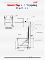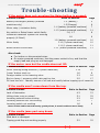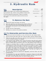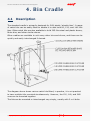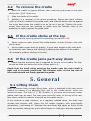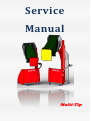
1
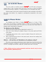
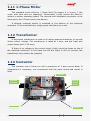
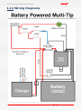
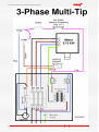
Service Manual Multi-Tip Multi-Tip Service Handbook for MULTI-TIP bin-tippers ® Index Diagram showing layout of parts ............................................................ ….2 Trouble Shooting ....................................................................................... 3 If the motor does not run when the Raise button is pressed: ............................. 3 If the motor runs but the cradle does not lift:.................................................. 3 If the cradle won’t come down from the top: ................................................... 3 If the cradle jams part-way down:................................................................. 3 General Overview ...................................................................................... 4 1. Electrical System.................................................................................... 4 1.1 General description............................................................................... 4 1.2 Battery ............................................................................................... 6 1.3 Battery Charger ................................................................................... 7 1.4 Motor relay (Battery-powered machines only) ........................................... 7 1.5 Lowering Valve Solenoid ........................................................................ 8 1.6, 1.7 Raise/Lower Switch,optional Key Switch/Emergency Stop Switch ........... 9 1.8 Personnel Detection System (if fitted)..................................................... 10 1.9 12 Volt DC Motor................................................................................. 10 1.10 3-Phase Motor .................................................................................. 10 1.11 1-phase motor .................................................................................. 11 1.12 Transformer ..................................................................................... 11 1.13 Contactor ......................................................................................... 11 1.14 Wiring Diagrams......................................................................... 12 - 14 2. Hydraulic Power Pack – Service ............................................................ 15 2.1 Description ......................................................................................... 15 2.2 To Remove Power Pack ........................................................................ 16 2.3 To Remove Lowering Valve ................................................................... 16 2.4 To Remove Pressure-compensating Lowering-speed Valve ......................... 17 2.5 Pressure-relief Valve ............................................................................ 17 3. Hydraulic Ram ..................................................................................... 18 3.1 Description ......................................................................................... 18 3.2 To Remove Ram.................................................................................. 18 3.3 To Dismantle and Service the Ram ......................................................... 18 3.4 Ram-end Rollers – Replacement ............................................................ 19 4. Bin Cradle ............................................................................................ 20 4.1 Description ......................................................................................... 20 4.2 To Remove Cradle ............................................................................... 21 4.3 If Cradle Sticks at Top.......................................................................... 21 4.4 If Cradle Jams Part Way Down .............................................................. 21 5. General ................................................................................................ 21 5.1 Lifting Chain ....................................................................................... 21 5.2 Castors.............................................................................................. 22 5.3 Tip guide flap ..................................................................................... 22 5.4 Spare Parts Identification Guide ............................................................. 22 Manufacturer Contact Details ................................................................... 23 © Copyright Simpro Handling Equipment 2005 1 Multi-Tip Service Handbook for MULTI-TIP bin-tippers ® Multi-Tip Bin Tipping Machine (Cradle shown in inverted position) © Copyright Simpro Handling Equipment 2005 2 Multi-Tip Service Handbook for MULTI-TIP bin-tippers ® Trouble-shooting If the motor does not run when the Raise button is pressed: Possible Causes Battery Discharged (battery-powered machines only) Motor relay / contactor faulty Key switch or Raise/Lower switch faulty Personnel Detection System not working properly (if fitted) Motor faulty Blown control-circuit fuse Refer to Section Page 1.2 (Battery) 1.3(Charger) 1.4 (battery-powered machines) 1.13 (mains-powered machines) 1.6, 1.7 5 6 7 11 8 1.8 9 1.9 (battery-powered machines) 1.10 (3-phase machines) 1.11 (1-phase machines) 1.11 (mains-powered machines) 10 10 11 11 Also check: For broken or disconnected wires. On mains-powered machines, that the power socket is live, and that the supply lead and plug are not damaged. If the motor runs but the cradle does not lift: Possible Causes Refer to Section Page Motor running wrong direction (3-phase machines) 1.10 10 ‘Lower’ button stuck on 1.6 8 Foreign matter in the lowering valve 2.3 16 Bin too heavy / pressure-relief valve set too low 2.5 17 Oil level too low: Identify source of oil leak and rectify before topping up oil reservoir If the cradle won’t come down from the top: Possible Causes Lack of lubrication Lifting chain rusty or seized Lowering solenoid valve sticking Lowering solenoid coil not working Lowering switch not working Refer to Section Page 4.3 5.1 2.3 1.5 1.6 21 22 16 7 8 Note: As the cradle comes down by gravity alone, it must be able to move freely If the cradle jams part-way down: Possible Causes Mast bent or damaged Tipping guide flap not working properly © Copyright Simpro Handling Equipment 2005 3 Refer to Section Page 5.2 22 Multi-Tip Service Handbook for MULTI-TIP bin-tippers ® General Overview The lifting power for Multi-Tip tippers comes from a hydraulic power pack, which may be battery or mains-powered. When the motor runs, hydraulic oil is forced under pressure into the lift ram, causing it to extend. The ram has a roller on the end; as it extends, a chain is pulled around the roller, and lifts the cradle. When the “DOWN” button is pressed, a solenoid valve opens and the hydraulic oil passes back into the tank at a controlled rate. The bin and cradle are not powered down – they come down by gravity alone. The whole action is smooth and efficient, and can handle very heavy bins continuously with little or no maintenance. 1. Electrical System 1.1 General description Multi-Tip tippers are powered by a hydraulic power pack, which has either a 12vdc, 1-phase (240vac), or 3-phase (400vac) motor. In all cases, when the ‘RAISE’ button is pressed, the motor runs and oil is forced into the lift ram under pressure, which makes the cradle go up. When the ‘LOWER’ button is pressed, a solenoid coil is energized, which opens a valve and allows oil back into the tank. The cradle comes down by gravity alone – it does not power down. The control circuit on battery-powered machines is 12vdc, and on mainspowered machines is 24vac. 3-phase motors are normally 0.75kw with no overload protection; 1-phase motors are generally 1.1kw with start and run capacitors and a thermal overload. Mains-powered machines can be fitted with an Auto-cycle device. This connects easily onto the standard wiring circuit, and has 3 built-in timers, to control Raise, Hold, and Lower time. IP Ratings (Environmental Protection) of the various parts are given below: Raise/Lower switch IP66 Key switch IP66 Emergency Stop (if fitted) IP66 Enclosure IP66 Motor IP55 © Copyright Simpro Handling Equipment 2005 4 Multi-Tip Service Handbook for MULTI-TIP bin-tippers 1.2 ® Battery Note: If the battery is flat or not holding its charge, or if the LED remains red after being on charge for several hours, check all the possibilities below before replacing the battery. 1. If the machine has not been used for several weeks the battery may have gone completely flat. If a battery has been sitting for weeks when discharged, it can take a few cycles to get back into its normal pattern. 2. The charger may not be charging, for some reason. Refer to the ‘testing’ paragraph of section 1.3 below. 3. The LED may be faulty, and flashing red even when the battery voltage is OK. Battery-powered machines normally have a sealed 18 amp-hour battery installed on the left side of the main box. Depending on the amount of usage, the battery should have a life of 1 – 2 years; if used continuously, or not maintained correctly, the life may be reduced. If desired, a 55 amp/hr gel battery can be fitted. This will give around 3 times as many empties on a charge. Removal and Refitting Remove the box cover panel, undo the terminal bolts, and lift the battery out. When replacing, ensure the positive terminal is to the right, and that the red cable is connected to the positive terminal. Testing Remove the box cover panel. Measure the battery voltage with a multimeter, with the charger disconnected. Plug the charger in, and measure the voltage again. Disconnect the charger, and measure the voltage again. Finally, measure it while pressing the RAISE button. If the voltage increases when the charger is connected, but drops below 12 volts when it is disconnected, the battery probably needs replacing. If the voltage does not increase when the charger is connected, check the charger (See Section 1.3) If the voltage drops more than 1.5 volts when the Raise button is pressed with no load on the cradle, the battery probably needs replacing. If you are unsure, or if the battery is less than 1 year old, return it to your battery supplier for testing Care Keep the battery clean and dry by wiping with a soft cloth. Ensure that both terminal clamps are securely tightened. Replacement Depending on the tipping height and other factors, a full charge of the battery should be sufficient to empty up to 3 - 5 tonnes of product. If the battery will not hold sufficient charge, and is at least a year old, it is probably due for replacement. Also check the battery charger as described in the following section. © Copyright Simpro Handling Equipment 2005 5 Multi-Tip Service Handbook for MULTI-TIP bin-tippers 1.3 ® Battery Charger Removal and Refitting 1. Undo the screws holding the outer cover panel and lift it off. 2. Disconnect the plug connecting the charger to the wiring loom. 3. Bend the retaining tab down with pliers or an adjustable spanner, and slide the charger out. 4. To replace, slide a new charger in, and bend the tab back up to retain it. 5. Connect the wiring plug and socket. Charger slides into brackets Bend retainer tab To Test: If the battery does not hold its charge, or will not accept a charge, the fault could be either the battery or the charger. Follow the steps below to determine whether the charger is working correctly: 1. Remove the access panel on the main box. 2. With a multi-meter in DC voltage mode, measure the voltage of the battery when the charger is not plugged in. It should normally be between 12.2 & 12.6 volts. 3. Plug the charger in, and check the voltage again. It should quickly rise to around 13 volts, then slowly increase to about 13.7 volts. 4. If the voltage doesn’t rise, check the wall socket, the charging lead, and the 2-way plug from the charger that connects into the loom. 5. The charger has input and output fuses. To check the output fuse, unscrew the fuse-holder from the rear face of the charger. The charger must be removed to check the input fuse, which is under a plastic tab beside the main socket. A spare input fuse is included beside the input fuse-holder. If the tests indicate a faulty charger, replace it as detailed above. © Copyright Simpro Handling Equipment 2005 6 Multi-Tip Service Handbook for MULTI-TIP bin-tippers 1.4 ® Motor relay (Battery machines only) To Test: 1. Remove the box cover panel. The relay is mounted on top of the motor. 2. The relay should ‘click’ when the RAISE switch is pressed. If there is no click, check that current is getting to the signal wires on the relay by connecting a multimeter to the wires and pressing the ‘up’ switch. If a signal is present but the relay does not ‘click’, it may be faulty. If no signal is present, check the wiring and switch. 3. If the relay ‘clicks’ but the motor does not run, hold a screwdriver across the two large terminals on the relay. If the motor runs, the contacts inside the relay are probably faulty and it should be replaced. If it still does not run, the fault is probably either the battery or the motor itself. Removal and Refitting 1. Disconnect the switching wires and cables from the relay, noting their position for correct replacement. 2. Remove the screws or band clamp holding the relay on to the motor. 3. Replace relay, reconnect the wires and test. 1.5 Lowering Valve Solenoid To Test: 1. The solenoid should make a faint ‘click’ when the ‘Lower’ switch is pressed. If not, the fault may be electrical or mechanical. If the wiring is OK, the red coil will be like a magnet when the Raise button is pressed (i.e. any small piece of steel should be attracted to it). 2. If the coil does not become magnetic, check the Raise/Lower switch and other wiring. 3. If the wiring is OK, check the coil itself. Remove the plug, then using a multimeter in 200 ohms range, hold a probe on the 2 opposite terminals; it should give a reading of between 6 and 8 ohms. 4. If the coil appears to be working properly, remove and check the valve as described in section 2.4 Removal and Refitting 1. Undo the knurled nut on the valve stem and remove the o-ring. 2. Remove the solenoid, noting which way around it goes. 3. Replace the correct way around, refit the o-ring and nut. The nut must be tightened FINGER-TIGHT ONLY. © Copyright Simpro Handling Equipment 2005 7 Multi-Tip Service Handbook for MULTI-TIP bin-tippers 1.6 Raise/Lower Switch ® Release clip Removal 1. The coupling plate and contact blocks can be unclipped from the top part by carefully pulling apart, while levering the release clip. 2. The individual contact blocks can also be removed if necessary, by unclipping from the coupling plate. 3. The top portion of the switch can be removed by unscrewing the nut under the control panel. When refitting, note that the small locating lug on the Raise/Lower switch in the cutout in the cover. 1.7 Contact block goes Key switch / optional Emergency-Stop switch Key Switch (39104) Emergency Stop Switch (19127) To Test and Refit 1. Test the individual contact blocks with a multimeter. If faulty, a contact block may be replaced rather than the complete switch. 2. Check that the switches are assembled correctly, are not sticking, and that the contact blocks are activated correctly. 3. Replace the top portion in the cover, and then clip the lower portion on. Note that they can only go one way round. © Copyright Simpro Handling Equipment 2005 8 Multi-Tip Service Handbook for MULTI-TIP bin-tippers 1.8 Personnel Detection System (Details available shortly) © Copyright Simpro Handling Equipment 2005 9 ® Multi-Tip Service Handbook for MULTI-TIP bin-tippers 1.9 ® 12 Volt DC Motor The motor used on a battery-powered Multi-Tip ® is an 800 watt, permanent- magnet type. It has 4 brushes which wear down over time; as they are difficult and time-consuming to replace, it is usually better to fit a complete new motor. Positive supply to the motor comes through the relay mounted on the side of the motor (see section 1.4); negative is permanently connected to the motor terminal. 1.10 3-Phase Motor The standard motor fitted to 3-phase Multi-Tip® tippers is a 2-pole, 0.75kw motor with a B-14 flange. An adaptor flange is bolted to the motor flange, and then to the hydraulic power pack. The motor only runs when the ‘Raise’ button is pressed, and is switched by a contactor. To Remove the Motor 1. Remove the entire power pack as described in section 2.1. 2. Undo the 4 bolts holding the adaptor flange to the power pack and lift the motor away. 3. If replacing with another motor, swap the adaptor flange and coupling over to the new motor. 4. When reassembling the motor to the power pack, ensure the coupling lines up with the pump shaft. Motor – Direction of Rotation (3-phase only)* The motor must rotate anticlockwise when viewed from the fan end, for the machine to operate. If rotation is incorrect, the motor will run but the cradle will not lift. To change the direction, swap any 2 phase wires over in the plug. (*Note: Wiring work on mains-powered machines should only be done by a competent, qualified person) © Copyright Simpro Handling Equipment 2005 10 Multi-Tip Service Handbook for MULTI-TIP bin-tippers ® 1.11 1-Phase Motor The standard motor fitted to 1-Phase Multi-Tip tippers is a 2-pole, 1.1kw motor with start and run capacitors. Occasionally 4-pole motors are fitted to achieve a slower operating speed. The removal and installation procedure is the same as for the 3-Phase motor (see above). A thermal overload switch is mounted in the bottom of the electrical enclosure. If the overload trips, simply press the button to re-set. 1.12 Transformer A step-down transformer is used on all mains-powered machines, to provide 24vac control voltage. The transformer is rated at 1 amp, and has input and output fuses (both 1.25 amp) If there is no voltage in the control circuit, firstly check the fuses on top of the electrical enclosure. If the fuses are OK but there is still no current, the transformer may need to be replaced. 1.13 Contactor The contactor has a 24vac coil with a maximum of 1 amp current draw. If replacement is necessary, we recommend that the same brand and model is used. Contactor Thermal Overload Input & Output Fuses Transformer © Copyright Simpro Handling Equipment 2005 Enclosure 11 Multi-Tip Service Handbook for MULTI-TIP bin-tippers 1.14 Wiring Diagrams © Copyright Simpro Handling Equipment 2005 12 ® Multi-Tip Service Handbook for MULTI-TIP bin-tippers © Copyright Simpro Handling Equipment 2005 13 ® Multi-Tip Service Handbook for MULTI-TIP bin-tippers © Copyright Simpro Handling Equipment 2005 14 ® Multi-Tip Service Handbook for MULTI-TIP bin-tippers ® 2. Hydraulic Power Pack 2.1 Description The motor driving the pump on Multi-Tip bin-tippers is either 800 watts (12VDC), 0.75kw (3-phase), or 1.1kw (1-phase). The motor, pump, oil tank, and all control valves are mounted into an integral unit, referred to as the ‘powerpack’. The four main control valves are: check, pressure-relief, solenoid lowering, and pressure compensating lowering-speed valves (this automatically keeps the lowering speed the same, regardless of the load on the cradle). The power-packs are very reliable and long-lasting, and no regular maintenance is required. Possible faults include: Foreign matter in the lowering valve (symptoms – raising slowly or not at all, coming back down without pushing the Lower button) Worn shaft or shaft seal (slow lifting, noisy operation, oil foaming) © Copyright Simpro Handling Equipment 2005 15 Multi-Tip Service Handbook for MULTI-TIP bin-tippers 2.2 ® To Remove the Power Pack ENSURE THE MACHINE IS DISCONNECTED FROM POWER SUPPLY! 1. Ensure cradle is fully lowered. 2. Undo the screws holding the outer cover and remove it. 3. Undo the swivel fitting (11/16") holding the hydraulic hose to the power pack, and plug or tape the fittings to prevent ingress of dirt. 4. Make note of the wiring connections to the motor and disconnect. Undo the knurled knob holding the lowering solenoid coil on, and remove it. 5. Undo the 2 bolts or screws securing the power pack and lift it away. Refitting Refitting is a reversal of the above procedure, with attention to the following points: 1. Ensure the wiring is reconnected the same as original. 2. Do not use thread sealant on the hydraulic fitting. 3. Test for correct operation before refitting the cover. 2.3 To Remove the Lowering Valve 1. Remove the coil as described in Section 1.5 2. Unscrew the valve from the main body using a 15/16" OR 24mm spanner. 3. Clean the valve carefully with compressed air. Ensure that the centre poppet can move freely, and then it seals firmly on the valve seat when released. 4. Clean the valve orifice before refitting the valve. 5. Refit the valve and coil. © Copyright Simpro Handling Equipment 2005 16 Multi-Tip Service Handbook for MULTI-TIP bin-tippers ® 2.4 To Remove the Pressurecompensating Lowering-speed Valve 1. Remove the lowering valve as described in section 2.3 2. Using long-nose pliers, pull the valve out from the orifice. 3. To replace, simply push into orifice, then replace the lowering valve. 2.5 Pressure-relief Valve The pressure-relief valve limits the maximum hydraulic pressure flowing to the ram, and thus the maximum weight that can be lifted. If the bin is heavier than the setting will allow, the motor and pump still run but the oil just bypasses straight back into the tank. While this does not do any harm to the machine, oil passing through the relief valve generates a lot of heat; for this reason, if the relief valve is ‘blowing’ frequently, either the setting should be increased, or the bin weight reduced. NOTE! Authorization must be obtained from the manufacturer, before any adjustment is made to the pressure-relief valve setting. Unauthorized adjustment may result in the warranty being cancelled. Adjustment 1. Remove the box cover. 2. The relief valve adjustment screw is located in the main powerpack body, on the near side of the pressure port (to which the hydraulic hose is connected). 3. Remove the outer cap, loosen the locknut then turn the screw clockwise to increase the pressure. 4. Test the capacity using a full bin. When pressure setting is sufficient, tighten the locknut and replace the cap. Refit the cover. NOTE: It is preferable to have the pressure set to only just a little higher than necessary to pick up the heaviest bins. © Copyright Simpro Handling Equipment 2005 17 Multi-Tip Service Handbook for MULTI-TIP bin-tippers ® 3. Hydraulic Ram 3.1 Description Multi-Tip bin-tippers use a single-acting displacementtype hydraulic ram, which is very reliable, but also easy to service should the need arise. There is no piston, just a seal in the head which seals onto the chromebar spear. 3.2 To Remove the Ram 1. Remove the upper and lower ram covers. 2. Undo the hydraulic hose fitting at the bottom of the ram. 3. Disconnect the chain from the adjusting bolt and tie up (e.g. to the mesh guard) to stop it falling down inside the mast. 4. Lift the ram out of the bracket. 5. Refitting is a reversal of the above procedure. 3.3 To Dismantle and Service the Ram 1. Hold the ram body horizontally in a vice, with the roller end slightly higher. 2. Pull the chrome-bar spear right out of the ram body, and lay carefully aside. 3. Take the ram body out of the vice, and pour the small amount of remaining oil into a suitable container for disposal. 4. If the seal has been leaking, pick it out of its groove near the end, using a small, sharp screwdriver. It is very difficult to remove without damaging it, and it is usually best to just stab it, pull it out, and replace it with a new one. 5. If there is a pinhole leak in a weld, it is generally best to fit a complete replacement ram body, and return the faulty one to Simpro for repair. If this is not feasible, mark the location of the hole, and grind a groove at least 3mm deep, and 10mm each side of the hole. If possible, weld using MIG or arc welder. If a welder is not available, it may be brazed, but difficulty may be experienced because of oil contamination. The seal will need to be replaced, if the hole is in the “head” weld. 6. The ram body should be cleaned with degreaser, and then blown out with compressed air. 7. To reassemble, fit a new seal (#R44035), if necessary. Smear oil on the seal and inside the head. Wipe the chrome bar carefully, then fit it back into the ram body, using a twisting action as it goes through the seal. © Copyright Simpro Handling Equipment 2005 18 Multi-Tip Service Handbook for MULTI-TIP bin-tippers ® 3.4 Ram-end Roller – Replacement 1. Lower the cradle to the ground, then remove the upper and lower ram covers. 2. Remove the Nylock nut on the chain adjustment bolt. Do not let the chain fall into the mast, as it is difficult to feed back up. Tie the end of the chain to the ram bracket. 3. Remove the circlip on one end of the roller axle and push or tap it through until the roller can be extracted. 4. When refitting, smear the inside of the roller liberally with grease, press the axle back through, and replace the circlip. © Copyright Simpro Handling Equipment 2005 19 Multi-Tip Service Handbook for MULTI-TIP bin-tippers ® 4. Bin Cradle 4.1 Description The standard cradle is primarily designed for 240l plastic ‘wheelie bins’. A range of catch kits can be easily fitted to enable it to also hold 80, 120, and 140 litre bins. Other catch kits are also available to hold 205-litre steel and plastic drums, Brute bins, and other similar drums. Other cradles are available to suit many other bins and drums, and these can be quickly and easily interchanged if desired. The diagram above shows various catch kits fitted; in practice, it is not practical to have multiple kits mounted simultaneously. However, the 120, 140, and 240l ones can be mounted together. The kits can be mounted or interchanged very simply, usually with 2 or 4 bolts. © Copyright Simpro Handling Equipment 2005 20 Multi-Tip Service Handbook for MULTI-TIP bin-tippers 4.2 ® To remove the cradle 1. Raise the cradle by approx 800mm, then undo the grub-screw in the outer shaft collar (3/16” Allen key). 2. Slide the cradle off the shaft. 3. Refitting is a reversal of the above procedure. Ensure the black follower roller is correctly located in the guide track, and slide the shaft collar up against the nylon bush when the cradle is on as far as it can go. Tighten the grubscrew, then test-run the machine to make sure the follower roller is not pressing too tightly against the guide track. 4.3 1. If the cradle sticks at the top Check that the lowering solenoid is operating (see section 1.5) 2. Spray inside the mast, around the cradle bushes, and the follower roller with silicon spray. 3. As the cradle comes down by gravity, it must have weight on the main axle to retract the ram. Ensure that nothing is affecting the balance of the cradle (for example, product sticking in the bin). 4.4 If the cradle jams part-way down 1. Check that the aluminium flap is triggered by the pin on the cradle. The flap should be lifted just before the roller comes back to it. Check that the shaft collar securing the cradle onto the main shaft is tight and is correctly positioned. The follower roller on the top axle of the cradle should run firmly against the guide. 5. General 5.1 Lifting Chain Multi-Tip tippers have a single lifting chain, which is attached to the ram mount bracket by means of an adjusting bolt, and to the “cradle-carrier” which run inside the mast. The chain is ½” BS Simplex; in corrosive environments nickelplated chain may be used. The chain goes around a roller on the top of the ram, then down inside the mast to a bracket on the cradle-carrier. If the machine is used outdoors, or is regularly washed down, the chain may corrode and become stiff. Spray the full length regularly with good-quality penetrating / lubricating oil. Unscrew the ram-cover and spray as much of the chain as possible, taking care not to allow fingers or clothing to become trapped. © Copyright Simpro Handling Equipment 2005 21 Multi-Tip Service Handbook for MULTI-TIP bin-tippers ® Removal / Replacement 1. Remove the cradle and 30mm shaft from the cradle-carrier. 2. Unscrew and remove the upper and lower ram covers. Either remove the Nylock nut on the adjusting bolt, or release the clip on the connecting link attaching the chain to the adjusting bolt. 3. Lift the machine or lie it over to allow the cradle carrier to come out the bottom of the mast. 4. The chain simply clips onto a bracket at the bottom of the cradle-carrier frame. 5. When refitting, adjust the Nylock nut so the cradle goes right to the ground, and the cradle-carrier stops just short of the top of the mast when fully raised. 5.2 Tipping Guide flap A cast aluminium flap is used to ‘switch’ the follower roller during the lifting and lowering cycle. The flap must move freely without sticking. A pin welded to the cradle lifts the flap when the cradle is approximately horizontal while lowering. The roller itself lifts the flap when the cradle is lifting. The cradle must be correctly located on the shaft for the flap to work properly. Adjust the shaft collar so the follower roller runs firmly against the guide. 5.3 Castors As standard, 4 castors with 125mm diameter ‘Blue Resilex’ wheels are fitted. The two castors at the “operator” end generally have brakes. The castors are secured to the base with a single M12 bolt through the centre. 5.4 Spare Parts Identification Guide Description/ Complete Ram: Ram Seal: Ram-end Roller: Raise/Lower Switch: Key Switch: Part No. 34000* 34103 39104 Description/ Part No. Emergency Stop: 19127 Non-braked 125mm Castor: 30100N Braked 125mm Castor: 301008 120-litre Conversion Kit: 140-litre Conversion Kit: *The ram length varies according to model. Please specify model and serial no. when ordering. The table above includes only the most common parts. A full list of parts is available from the manufacturer, or may be downloaded from the website www.simpro.net.nz © Copyright Simpro Handling Equipment 2005 22 Multi-Tip Service Handbook for MULTI-TIP bin-tippers Also available from Simpro Handling Equipment Ltd: Dumpmaster Heavy-duty bin-tippers Manufacturer Contact Details: If more information relating to any part of this Service Manual is required, please contact the manufacturer: Simpro Handling Equipment Free call – Australia 1800 25 00 59 – New Zealand 0800 734 744 Fax (+64) 9 634 7438 PO Box 13-679, Onehunga, Auckland, New Zealand Email: [email protected] © Copyright Simpro Handling Equipment 2005 Website: www.simpro.net.nz 23 ®