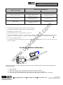
1
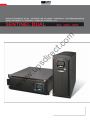
ct re di .u ps w w w .c om USER’S MANUAL 41 w w w .u ps di re ct .c om GB 6 SAFETY 2 INTRODUCTION Thanks you for choosing this product of the Sentinel Dual range. Riello UPS are renowned specialists in the development and production of uninterruptible power supplies (UPS). The UPS in this range are high quality products, designed and built with care in order to give you the best performance. This equipment can be installed by anyone, subject to CAREFULLY AND THOROUGHLY READING THIS MANUAL. .c om The manual contains detailed instructions on how to use and install the UPS. For information on using and getting the best performance from your UPS, this manual should be kept safely in the vicinity of the UPS and CONSULTED BEFORE TAKING ANY ACTION ON THE UPS. ENVIRONMENTAL PROTECTION ct During the development of its products, the company uses extensive resources with regards to all environmental aspects. re All our products pursue the objective defined in the environmental management system developed by the company in compliance with standards in force. No hazardous materials such as CFC, HCFC or asbestos are used in this product. .u ps di When evaluating packaging, the choice of material has been made favouring recyclable materials. For correct disposal, please separate and identify the type of material of which the packaging is made in the table below. Dispose of all material in compliance with standards in force in the country in which the product is used. Material Heat-treated pine Stratocell/cardboard Cardboard Stratocell HD Polyethylene w w w Description Pallet Packaging corner Box Adhesive pad Protective bag DISPOSING OF THE PRODUCT The UPS contains internal material that (in case of dismiss / disposal) are considered TOXIC and HAZARDOUS WASTE, such as electronic circuit boards and batteries. Treat these materials according to the laws applicable referring to qualified service personnel. Their proper disposal contributes to respect the environment and human health. © Reproduction of any part of this manual, including partial, is strictly prohibited without the prior consent of the manufacturer. For the purpose of improving it, the manufacturer reserves the right to modify the product described herein at any time and without notice. 3 CONTENTS 5 UPS VIEWS 6 DISPLAY MASK VIEW 7 INSTALLATION 8 OPENING THE PACKING AND CHECKING CONTENTS 8 TOWER VERSION 9 RACK VERSION USE CONNECTIONS AND SWITCHING ON FOR THE FIRST TIME SWITCHING ON FROM THE MAINS ct SWITCHING ON FROM THE BATTERY Configuration area .u ps Measurements display area di UPS status indicators re SWITCHING THE UPS OFF DISPLAY PANEL INDICATIONS .c om PRESENTATION 10 11 11 11 11 11 12 12 13 15 MODES OF OPERATION 16 UPS CONFIGURATION 17 COMMUNICATION PORTS 19 19 Communication Slot 19 w w RS232 and USB connectors SOFTWARE 20 20 Configuration software 20 w Monitoring and control software BATTERY PACK REPLACEMENT OF THE BATTERY PACK PROBLEM SOLVING ALARM CODES 21 21 22 24 TECHNICAL DATA TABLE 26 FERRITE INSTALLATION ADDENDUM 27 4 PRESENTATION .u ps Tower di re ct .c om The new Sentinel Dual UPS family has been designed with a special eye to versatility. These UPS, depending on the user’s requirements, can in fact be installed either in tower version or in rack version (by means of a suitable handles kit option). The 2 different product versions are shown below: Rack w w w The UPS also has a dedicated battery pack that permits easy replacement of the batteries (hot swap), entirely safely for the operator, thanks to the protected connection system. Nominal power Nominal voltage Dimensions H x L x D Weight SDL 3300 [VA] [Vac] [mm] [Kg] SDL 4000 3300 4000 220 / 230 / 240 455 x 175 x 520 (1) 38 (1) In the rack version, with the handles installed, the H dimension changes as follows: 483mm x 175mm x 520mm (H x L x D) Note: 175mm = 4U 483mm = 19” 5 PRESENTATION UPS VIEWS Release slots Extractable/rotatable display mask Manual bypass switch .c om General switch Cable with terminal Removable front panel (front panel on) .u ps di (front panel off) Front view re ct Battery pack w w w USB communication port RS232 communication port COMMUNICATION SLOT Expansion slot Input thermal protection Cooling fans IEC 16A Inlet Battery expansion connector IEC 10A outlets IEC 16A outlet Rear view 6 PRESENTATION DISPLAY MASK VIEW .c om “SEL / SET” button “ON” button di re ct “STBY” button w w w .u ps LCD Display 1 Operating normally 7 Configuration area 2 Operating on mains power 8 Maintenance action required 3 Operating on battery power 9 Timer 4 Load powered from bypass 10 Measurements display area 5 Battery back-up indicator 11 Stand-by/alarm 6 Load level indicator 7 INSTALLATION OPENING THE PACKING AND CHECKING CONTENTS After opening the pack, the first thing to do is make a check of the contents. The pack should contain: UPS 2 plastic covers (top panels) .c om 2 plastic keys for releasing the display 2 IEC 10A connection cables RS232 serial cable w w w .u ps di re ct Power cord (Schuko plug –IEC 16A socket) IEC 16A spare socket User manual + CD-ROM with software User's manual 8 INSTALLATION TOWER VERSION This chapter describes the work needed to prepare the UPS for use in tower version. WARNING: for your own safety and that of your product, it is important that you follow the instructions given below exactly. .c om BEFORE PROCEEDING TO PERFORM THE SEQUENCE OF OPERATIONS DESCRIBED, MAKE SURE THAT THE UPS IS SWITCHED OFF COMPLETELY AND IS NOT CONNECTED TO THE ELECTRICAL MAINS OR LOAD OF ANY KIND ct Once removed from its packaging, the UPS is already prepared for installation in tower configuration. To complete the configuration, all that is needed is to fit the two plastic covers provided on the top part of the UPS, as described below: re the 2 covers have a snap-fit fastening system: identify the special holes for mounting of the covers in the top part of the UPS and, taking the utmost care, fit the covers exerting a slight pressure (see figure to the side). w w w .u ps di Note: as the covers are perfectly identical, they can both be fitted in either of the areas (front/back) on the top of the UPS without any problem. 9 INSTALLATION RACK VERSION This following describes the work needed to convert the UPS into rack version. WARNING: for your own safety and that of your product, it is important that you follow the instructions given below exactly. BEFORE PROCEEDING TO PERFORM THE SEQUENCE OF OPERATIONS DESCRIBED, MAKE SURE THAT THE UPS IS SWITCHED OFF COMPLETELY AND IS NOT CONNECTED TO THE ELECTRICAL MAINS OR LOAD OF ANY KIND .c om 2 ct 1 re 1 - First and foremost, remove the 4 feet on the bottom of the UPS. Set the UPS horizontal, taking the utmost care and using a small, flat blade screwdriver lift gently the pin placed in the centre of the foot. Once raised, take the pin out from the base of the UPS. Repeat this sequence for the other remaining feet. The exact sequence is depicted in the figure to the side: .u ps di 2 - With all the feet removed, now proceed to rotate the display mask. Slip the keys provided into the release slots on the sides of the display mask and exert a slight pressure, just enough to release the mask from the UPS, as demonstrated in the drawing on the side. w 3 - WARNING: The display mask is connected to the UPS by a special cable. This means that you must extract the mask taking extreme care and avoiding violent jerks or other brusque movements, so as to avoid possibly damaging the display and/or the UPS. DO NOT TRY IN ANY WAY TO SEPARATE THE DISPLAY MASK FROM THE UPS. w 4 - Rotate the mask by 90° in the anti-clockwise direction and fasten it to the UPS again, inserting it gently into the housing until a slight clicking noise is heard and the mask remains in position. w 5 - Rotate the UPS by 90° clockwise taking the utmost care. 6 - At this point, with the UPS in the horizontal position, attach the handles to the side of the UPS with the appropriate screws as depicted in the figure to the side. (handles and screws are include in the handles kit option) NOTE: The UPS is compatible with assembly in standard rack cabinets of 600mm x 800mm or greater (in depth). In rack type installation, given the weight of the UPS, use of the support brackets is compulsory (guide with L-shape support). For the same reason, it is recommended that you install the UPS in the bottom part of the rack cabinet. 10 USE CONNECTIONS AND SWITCHING ON FOR THE FIRST TIME Install upstream of the apparatus a 16A magneto-thermal switch with intervention curve B or C. Connect the power cord supplied with the UPS to the IEC 16A inlet socket. Connect the power cord from the UPS to the mains. Press the main switch on the front panel. 5) After a short time, the UPS comes on, the display lights, a beep sounds and the icon blinks. The UPS is in stand-by mode: this means that the UPS is in a minimum consumption condition. The microcontroller is powered and performs its supervision and self-test task; the batteries are charging; everything is ready for activation of the UPS. There is also a stand-by operating mode when in battery-powered operation, provided the timer has been activated. Connect the item(s) of equipment to be powered to the outlets on the rear of the UPS using the cable supplied or another cable of max. length 10 metres. WARNING: do not connect equipment that absorbs more than 10A to the IEC 10A outlets. For equipment items exceeding this level of absorption, use only the IEC 16A socket. Check the machine settings on the display (see the section: Configuration area) 6) 7) .c om 1) 2) 3) 4) ct SWITCHING ON FROM THE MAINS Press the “ON” button. After it has been pressed, all the icons on the del display light for 1 second and the UPS sounds a beep. 2) Switch on the equipment item(s) connected to the UPS. Only when switching on for the first time: after about 30 sec. have elapsed, check that the UPS is working properly: 1. Simulate a black-out by opening the switch placed upstream of the UPS. 2. 3. .u ps di re 1) The load must continue to be powered, the icon on the display must light, and a beep must be heard every 4 seconds. When the upstream switch is closed again, the UPS should return to mains-powered operation. w 3) Press the main switch on the front panel. Hold the “ON” button down for at least 5 seconds. All the icons on the display light for 1 second and the UPS sounds a beep. Switch on the equipment item(s) connected to the UPS. w 1) 2) w SWITCHING ON FROM THE BATTERY SWITCHING THE UPS OFF To switch the UPS off, hold down the “STBY” button for at least 1.5 seconds. The UPS returns to stand-by icon starts blinking: mode and the a. If the mains line is up, to switch the UPS off completely, press the main switch, bringing this switch back into its original position (raised position). b. If the UPS is on battery-powered operation and the timer has not been set, it switches off completely and automatically after 5 seconds. If on the other hand, the timer is set, to switch the UPS off, hold the “STBY” button down for at least 5 seconds. If you want the UPS to remain switched off completely when the mains power returns, then press the main switch (see step a.). 11 USE DISPLAY PANEL INDICATIONS This chapter will describe in depth all the items of information that may be posted on the LCD. For easier understanding, we can divide the information displayed into three main groups: UPS status indicators Measurements display area Configuration area UPS status indicators DESCRIPTION Fixed Indicates presence if a problem Blinking The UPS is in stand-by mode Fixed Indicates UPS operating normally .c om STATUS ct ICON The UPS is working on battery power. When in this condition, the UPS emits a beep at 4-second regular intervals. .u ps Fixed The UPS working on mains power, but the output voltage is not synchronized with the mains voltage di Blinking The UPS is working on mains power re Fixed End of discharge early warning. Indicates that the battery’s back-up is running out. In this condition, the UPS emits a beep at 1-second regular intervals. Fixed Indicates that the loads connected to the UPS are being powered by the bypass w w w Blinking Dynamic Indicates the estimated percentage back-up Dynamic Indicates the % load applied to the UPS with respect to the nominal value Blinking Maintenance action is needed Fixed Blinking 12 Indicates that the timer is activated (programmed switch-on or switchoff). The timer can be activated/de-activated through the software supplied 1 minute to go before the UPS is switched on again or 3 minutes until it is switched off USE Measurements display area The most important measurements relating to the UPS may be displayed on the display screen. When the UPS is switched on, the display shows the mains voltage value. To move on to display something else, press the “SEL / SET” button repeatedly until the desired measurement value appears. If a failure/alarm occurs (FAULT) or the machine stops (LOCK), the display will automatically display the type of problem and the corresponding alarm code. A number of examples are shown below: (1) DESCRIPTION Current absorbed by the load .c om SAMPLE GRAPHIC Mains voltage Temperature of the cooling system of the UPS internal electronics re Fault / Alarm (2): the corresponding code is displayed Lock (2): the corresponding code is displayed .u ps di UPS output voltage ct Mains frequency Output voltage frequency w w Remaining battery backup w Battery charge percentage SAMPLE GRAPHIC (1) DESCRIPTION Total battery voltage Percentage load applied 13 The values given in the pictures of the table are purely indicative. (2) The FAULT / LOCK codes will only be displayed if they are active at that time (in presence of a failure/alarm or machine stoppage). w w w .u ps di re ct .c om (1) USE Configuration area The configuration area contains the main operating parameters of the UPS and displays its current status. The parameters found in this area can be modified by taking action directly from the display panel. SETTABLE PARAMETERS: Frequency: output voltage frequency Frequency Voltage: Output voltage Mode: UPS operating mode Voltage .c om Mode re ct The picture to the side depicts the area of the display reserved for settings (configuration area), with the three settable parameters in view. How to proceed: di To enter the configuration area hold down the “SEL / SET” button for at least 2 sec. The word “SET” lights and an arrow ( ► ) appears to the left of Frequency. .u ps The arrow indicates the setting selected. To change the selection of the parameter to be modified, press the “SEL / SET” button. To change the item selected, press the “ON” button. To exit from the configuration area, hold the “SEL / SET” button down for at least 2 sec. □ 60 Hz □ Off (frequency self-teach) □ 220 V □ 230 V □ 240 V □ ECO □ SMART w Voltage: □ 50 Hz w Frequency: w POSSIBLE SETTINGS Mode: □ ON LINE □ STBYOFF NOTE: For the change in configuration of output frequency to become effective, the UPS must be switched off completely and switched on again (by the main switch). THE PARAMETERS VOLTAGE AND OUTPUT FREQUENCY MUST BE COMPATIBLE WITH THOSE OF THE LOAD POWERED BY THE UPS 15 USE MODES OF OPERATION The mode that gives the load maximum protection is ON LINE mode (default), where the energy intended for the load undergoes a double conversion and is reconstructed on the output in a perfectly sinusoidal way with frequency and voltage fixed by the precision digital control provided by a microprocessor fully independently of the input (V.F.I.). * Besides the traditional ON LINE double conversion operating mode, it is also possible to set the following modes: ECO (LINE INTERACTIVE) SMART ACTIVE (shown on the display as “SMART”) .c om STAND-BY OFF (shown on the display as “STBYOFF”) For optimized efficiency, in ECO mode, the load is powered normally from the bypass. If the mains exits from its specified tolerances, the UPS switches to the normal ON LINE double conversion operating mode. About five minutes after the mains has returned inside tolerance, the load is again switched to bypass. re ct Where a user is unable to decide between the most suitable operating mode (ON LINE or ECO), he can leave the choice to SMART ACTIVE mode in which, in relation to statistics regarding the quality of the mains power supply, the UPS autonomously decides which mode to configure itself in. w w w .u ps di Finally in STAND-BY OFF mode, operation is as a back-up device: with mains line present, the load is powered down, whereas when a black-out occurs the load is powered by the inverter through the batteries. * The output voltage rms value is fixed by precision, microprocessor control independently of the input voltage, whereas the output voltage frequency is synchronised (inside a tolerance that is user-settable) with that of the input to allow use of the bypass. Outside this tolerance range, the UPS desynchronises, adopting the nominal frequency and the bypass cannot be used any more (free running mode). USE UPS CONFIGURATION The following table illustrates all the possible configurations that users have at their disposal to best adapt the UPS to their needs. LEGEND: Indicates that the configuration can be modified, both via the configuration software supplied and also by means of action on the display panel. = Indicates that the configuration can be modified only through the configuration software supplied. Output frequency Selects the nominal output frequency PREDEFINED Auto Output voltage Selects the nominal output voltage Operating mode Selects one of the 4 different modes of operation ON LINE Delay time for automatic switching on again after the mains returns 5 sec. .u ps w 50 Hz 60 Hz Auto: automatic self-teaching of the input frequency 220V 230V 240V 220 ÷ 240 in steps of 1V (only through the software) ON LINE ECO SMART ACTIVE STAND-BY OFF Disabled 1 ÷ 255 in steps of 1 sec. Switch-off due to minimum load Automatic UPS switch-off when in battery-powered operation, if the load is less than 5% Disabled Enabled Disabled Back-up limitation Maximum battery operation time Disabled Disabled (full battery discharge) 1 ÷ 65000 in steps of 1 sec. End of discharge early warning Estimated remaining back-up time for the end of discharge early warning 3 min. w MODE di 230V w Switch-on delay POSSIBLE CONFIGURATIONS ct DESCRIPTION re FUNCTION .c om = 1 ÷ 255 in steps of 1 min. 17 USE DESCRIPTION PREDEFINED POSSIBLE CONFIGURATIONS Battery test Time interval for the automatic battery test 40 hours Disabled 1 ÷ 1000 in steps of 1 hour Alarm threshold for maximum load Selects the overload user limit Disabled Disabled 0 ÷ 103 in steps of 1% Display brightness Selects the level of brightness of the LCD Maximum Minimum ÷ Maximum in 20 steps Sound alarm Selects the mode of operation of the sound alarm Reduced Normal Reduced: does not sound for momentary intervention of the bypass .c om FUNCTION Selects the sensitivity of intervention during operation in ECO mode Normal w w Sensitivity of intervention for ECO mode Low: 180V High: 264V Selects the permitted Low: 200V voltage range for ECO High: 253V mode operation w Bypass voltage thresholds for ECO Load power supply in standby Bypass operation Power supply of the load on bypass with UPS switched of (stand-by status) Selects the mode for use of the bypass line ± 0.25% ± 0.5% ± 0.75% ± 1 ÷ ±10 in steps of 1% re Selects the permitted voltage range for switchover to bypass di Bypass voltage thresholds ± 5% .u ps Input frequency tolerance Selects the permitted range for the input frequency for switchover to bypass and for output synchronization ct ADVANCED FUNCTIONS Disabled (load NOT powered) Normal Low : High: 180 ÷ 200 in steps of 1V 250 ÷ 264 in steps of 1V Low:180 ÷ 220 in steps of 1V High: 240 ÷ 264 in steps of 1V Low Normal High Disabled (not powered) Enabled (powered) Normal Disabled with input/output synchronization Disabled without input/output synchronization MODE USE COMMUNICATION PORTS The following communication ports are found on the rear of the UPS (see UPS Views): RS232 connector USB connector Expansion slots for additional COMMUNICATION SLOT interface cards RS232 and USB connectors USB CONNECTOR .u ps di SIGNAL Contact closed: UPS stopped * TXD RXD PIN # 1 2 3 4 4 3 1 2 SIGNAL VBUS DD+ GND GND +12Vdc interface power supply input Contact closed: end of discharge early warning * Contact closed: battery-powered operation * w PIN # 1 2 3 4 5 6 7 8 9 re ct .c om RS232 CONNECTOR w * Optoisolated contact max. +30Vdc / 10mA w Communication Slot The UPS is provided with an expansion slot for optional communication cards (see the figure to the side) that enable the machine to carry out dialog using the main communication standards. Some examples: Second RS232 port Serial port duplexer Ethernet network agent with TCP/IP, HTTP and SNMP protocol RS232 + RS485 port with JBUS / MODBUS protocol UPS For more information on the accessories available, consult the manufacturer’s web site. 19 USE SOFTWARE UPS PC .c om RS232 Monitoring and control software Installation procedure: re ct The PowerShield3 software provides effective and intuitive management of the UPS, displaying all the most important information, such as input voltage, load applied, and battery capacity. It is also able to automatically effect operations such as shutdown, transmission of e-mails, SMS and network messages when particular events that can be selected by the user occur. w .u ps di Connect the UPS’s RS232 communication port to a COM communication port on the PC by means of the serial cable provided* or connect the USB port on the UPS to a USB port on the PC using a USB standard cable*. Download the software from www.riello-ups.com, selecting the desired operating system. Follow the installation program instructions. For more detailed information about installation and use, refer to the software manual which can be downloaded from our website www.riello-ups.com. w Configuration software w Using special software, it is possible to configure the most important UPS parameters. For a list of possible configurations, refer to the UPS configuration paragraph. * You are advised to use a cable of max. length 3 metres. BATTERY PACK REPLACEMENT OF THE BATTERY PACK As indicated in the presentation, the UPS is provided with a dedicated battery pack that permits easy replacement of the batteries (hot swap), entirely safely for the operator, thanks to the protected connection system. WARNING: for your own safety and that of your product, it is important that you follow the instructions given below exactly. .c om WHEN THE BATTERY PACK IS DISCONNECTED, THE LOADS CONNECTED TO THE UPS ARE NOT PROTECTED AGAINST A MAINS FAILURE. THE BATTERY PACK IS VERY HEAVY. TAKE ALL DUE CARE WHEN PERFORMING SUBSTITUTION. re ct 1 - The battery pack is located behind the front panel of the UPS. Take the panel centrally by the sides and pull gently outwards as shown in the figure to the side. In doing so, do not force the panel fastening pins too much. RNING ! WA .u ps RNING ! WA di RNING ! WA w w w 3 - The battery pack is connected to the rest of the UPS by means of a cable with terminal. See the figure on the side: press the 2 tabs on the sides of the terminal ( A ) and take it out pulling gently upwards. With your thumbs, together press the 2 fastening catches ( B ) and, keeping them pressed, put your index fingers into the slot located under the connector ( C ). RNING ! WA 2 - Put the manual bypass switch located under the front panel to position “II” (see figure to the side). WARNING: in this condition, the load is powered by the bypass and the display must show the message FAULT: C02. WARNING: For proper operation of the UPS, it is recommended that you replace the battery pack only with the UPS switched on. See the instruction manual before disconnecting the battery connector Press the switch in the position ‘II’ before changing the battery pack A A B B C 4 - Maintaining the position described in the previous step, take out the battery pack pulling outwards as shown in the figure to the side. Take great care when extracting the battery pack as it is very heavy. WARNING: the new battery pack and the one to be replaced must contain the same number and type of batteries (see the label next to the connector on the battery pack). 5 - Insert the new battery pack in its seat by sliding until it clicks into the UPS. Connect the cable with terminal again to its connector, put the switch back to position “I” and close the front panel. Make sure that the display returns to the normal display mode. 21 PROBLEM SOLVING Very often improper operation of the UPS does not indicate a failure, but is due solely to banal problems, drawbacks or lack of attention. You are therefore recommended to carefully consult the table below which summarizes the information needed to solve the most common problems. POSSIBLE CAUSE MAIN SWITCH NOT PRESSED Press the main switch on the front panel. Connect the battery pack connector, following the instructions in the section “REPLACEMENT OF THE BATTERY PACK”. MAINS CONNECTION CABLE MISSING Check that the power cord is connected properly. .c om THE BATTERY PACK CONNECTOR IS DISCONNECTED MAINS VOLTAGE MISSING (BLACK-OUT) Check that there is live voltage in the outlet the UPS is connected to (by testing, for example, with a table lamp). INPUT THERMAL PROTECTION TRIGGERED Reset the protection by pressing the button on the rear of the UPS (CIRCUIT BREAKER). WARNING: Check that there is no overloading on the UPS outlet. THE UPS IS IN STAND-BY MODE Press the “ON” button on the front panel to power the loads. THE STAND-BY OFF MODE IS SELECTED You must change mode. STAND-BY OFF mode (back-up) powers the loads only when there is a black-out. .u ps THE DISPLAY IS ON BUT THE LOAD IS NOT BEING POWERED di re THE DISPLAY DOES NOT LIGHT SOLUTION ct PROBLEM CONNECTION TO THE LOAD Check the connection to the load. IS MISSING Reset the protection by pressing the button on the rear of the UPS (CIRCUIT BREAKER). WARNING: Check that there is no overloading on the UPS outlet. INPUT VOLTAGE OUTSIDE THE PERMITTED VOLTAGE RANGE FOR MAINSPOWERED OPERATION Problem depending on the mains. Wait for the input mains to come back into tolerance. The UPS will automatically go back into mains-powered operation. THE UPS DOES NOT COME ON AND THE DISPLAY SHOWS ONE OF THE CODES: A06, A08 UPS TEMPERATURE LESS THAN 0°C Check the UPS surrounding ambient temperature; if too low, bring temperature to above the minimum threshold (0°C). THE DISPLAY SHOWS CODE: A11 INPUT RELAY STUCK This fault does not produce any particular malfunctions. However, if the problem occurs again the next time the UPS is switched on, get in touch with the service centre. w INPUT THERMAL PROTECTION TRIGGERED w w THE UPS IS WORKING ON BATTERY POWER DESPITE THE FACT THAT MAINS VOLTAGE IS PRESENT PROBLEM SOLVING PROBLEM POSSIBLE CAUSE THE BUZZER SOUNDS CONTINUOUSLY AND THE DISPLAY POSTS ONE OF THE CODES: A54, F50, F51, F52, F55, L50, L51, L52 SOLUTION THE LOAD APPLIED TO THE Lower the load to inside the 100% threshold (or user UPS IS TOO HIGH threshold in case of code A54). BATTERIES NEED TO BE REPLACED Replace the battery pack with a new one (as indicated in the chapter BATTERY PACK). THE DISPLAY SHOWS CODE: A62 BATTERY PACK MISSING OR NOT CONNECTED Check that the battery pack is inserted and connected correctly (see the chapter BATTERY PACK). THE DISPLAY SHOWS CODE: A63 BATTERIES ARE DISCHARGED; THE UPS IS WAITING FOR THE BATTERY VOLTAGE TO EXCEED THE SET THRESHOLD Wait for the batteries to recharge or manually force switching-on by holding the “ON” button down for at least 2 sec. THE BUZZER SOUNDS CONTINUOUSLY AND THE DISPLAY POSTS ONE OF THE CODES: F03, F05, F07, F10, F13, F21, F40, F41, F42, F43 A UPS MALFUNCTION IS TAKING PLACE; SHUTDOWN IMMINENT THE BUZZER SOUNDS CONTINUOUSLY AND THE DISPLAY POSTS ONE OF THE CODES: F04, L04 TEMPERATURE OF THE HEAT SINKS INSIDE THE UPS IS TOO HIGH re ct .c om THE DISPLAY SHOWS CODE: A61 .u ps di If it is possible to power down the load, switch off the UPS and switch it on again; if the problem occurs again, contact the service centre. Check that the UPS surrounding ambient temperature is not in excess of 40°C. w w THE BUZZER SOUNDS FAULT DETECTED ON ONE Disconnect all the loads and connect them up again one CONTINUOUSLY AND THE OR MORE LOADS POWERED DISPLAY POSTS ONE OF by one to identify the faulty one. BY THE UPS THE CODES: F53, L53 A UPS MALFUNCTION HAS OCCURRED THE DISPLAY SHOWS ONE OF THE CODES: C01, C02, C03 A REMOTE COMMAND IN PROGRESS w THE BUZZER SOUNDS CONTINUOUSLY AND THE DISPLAY POSTS ONE OF THE CODES: F60, L03, L05, L07, L10, L13, L20, L21, L40, L41, L42, L43 If it is possible to power down the load, switch off the UPS and switch it on again; if the problem occurs again, contact the service centre. If undesired, check the position of the manual bypass switch or status of the control inputs of an optional contacts card. 23 PROBLEM SOLVING ALARM CODES By using a sophisticated self-test system, the UPS can check and report on the display panel any problems and/or failures that could occur during normal operation of the equipment. In case of a problem, the UPS signals the event by posting on the display the code and type of alarm present (FAULT and/or LOCK). FAULT The FAULT type reports may be divided into three categories: Failures: these are “minor” problems that do not result in the UPS stopping but they limit its performance or prevent certain features being used. DESCRIPTION A06 A08 A11 A54 A61 A62 A63 Temperature sensor1 less than 0°C .c om CODE Temperature sensor2 less than 0°C Input relay stuck (does not open) ON LINE: load > of the user threshold - ECO: load > 16A * ct Batteries need replacement Battery pack missing or not connected re Waiting for batteries to recharge w w w F03 F04 F05 F07 F10 F13 F21 F40 F41 F42 F43 F50 F51 F52 F53 F55 F60 .u ps CODE di Alarms: these problems are more critical than the failures because – if they continue – they could cause the UPS to stop, even in a very short time frame. DESCRIPTION Auxiliary power supply incorrect High temperature on heat sinks Temperature Sensor1 broken Temperature Sensor2 broken Input fuse broken or input relay stuck (does not close) Capacitor precharging failure Capacitor bank overvoltage Inverter overvoltage D-C voltage on output Inverter voltage not right Inverter undervoltage Overload: load > 103% Overload: load > 110% Overload: load > 150% Short-circuit Waiting for load reduction before return to inverter Battery overvoltage PROBLEM SOLVING Commands in progress: Indicates presence of a remote command in progress. CODE DESCRIPTION C01 C02 C03 C04 Remote shutdown command Remote load on bypass command Remote switch-on command Battery test in progress .c om LOCK The LOCK (block) type report signals are usually preceded by an alarm signal and, on account of their importance, result in the inverter being switched off and the load being powered through the bypass line (the procedure is excluded in case of lockouts due to strong and persistent overloads and lockouts following a short-circuit). DESCRIPTION L03 L04 L05 L07 L10 L13 L20 L21 L40 L41 L42 L43 L50 L51 L52 L53 Auxiliary power supply incorrect ct CODE re High temperature on heat sinks Temperature Sensor1 broken Temperature Sensor2 broken di Input fuse broken or input relay stuck (does not close) w w w .u ps Capacitor precharging failure Capacitor bank undervoltage Capacitor bank overvoltage Inverter overvoltage D-C voltage on output Inverter voltage not right Inverter undervoltage Overload: load > 103% Overload: load > 110% Overload: load > 150% Short-circuit * In ECO mode, the load is normally powered by the bypass. Therefore, in the presence of a load of constant power, the current absorbed depends on the mains voltage, which may accordingly be in excess of the value allowed by the input plug and the protection upstream. When this situation arises, the UPS reports a failure which automatically disappears if the input voltage increases and/or the output load is reduced. 25 5- TECHNICAL DATA TABLE MODELS SDL 3300 BYPASS Accepted voltage range for switching Accepted frequency range for switching Switching time BATTERY Back-up time No. batteries / V / Ah Recharge time [Vac] w .u ps di [Vac] [VA] [W] [mA] [°C] w Hold-up time Noise level Dimensions H x L x D Weight 6’ / 2300 5’30 / 2400 9 / 12 / 7 high rate discharge 4÷8 re [h] w MISCELLANEOUS Leakage current to earth AC/AC efficiency Ambient temperature (6) Humidity Protections 180 ÷ 264 Frequency selected ±5 % Typical: 2 - Maximum: 4 [msec] [min / W] OUTPUT Nominal voltage (7) Static variation (3) Dynamic variation (4) Waveform Voltage distortion @ linear load Voltage distortion @ distorting load Frequency (5) Current crest factor Nominal power Nominal power .c om Nominal frequency Maximum current (1) Nominal current (2) Power factor Current distortion @ maximum load [Vac] 220 / 230 / 240 [Vac] 0 ÷ 276 [Vac] Maximum: 276 [Vac] Minimum: 164 ÷ 84 (from 100% to 50% of load in linear mode) [Vac] Return to mains-powered operation: 180 [Hz] 50 - 60 +5 [A] 15 16 [A] 11 12 0.98 7% ct INPUT Nominal voltage Accepted range Voltage range ruling out battery intervention SDL 4000 [msec] [mm] [Kg] 3300 2300 220 / 230 / 240 ±1.5% 1.5% 5% in 20 msec Sinusoidal 3% 6% 50 or 60 Hz selectable 3:1 4000 2400 1 92% 0 – 40 < 90% non-condensing Excessive battery discharge – Overcurrent – short-circuit – Overvoltage – undervoltage - thermal 40 < 40 dB(A) at 1 mt. 455 x 175 x 520 38 38 6- TECHNICAL DATA TABLE OPERATION POWERED BY OVERLOAD TIMES INVERTER 100% < Load 110% Activates bypass after 2 sec Stoppage after 120 sec Stoppage after 60 sec 110% < Load 150% Activates bypass after 2 sec Stoppage after 4 sec Stoppage after 4 sec Load > 150% Activates bypass instantaneously Stoppage after 1 sec Stoppage after 0.5 sec .c om BYPASS @ nominal load, minimum voltage of 164 Vac, battery charging (2) @ nominal load, nominal voltage of 230 Vac, battery charging (3) Mains/Battery @ load 0% -100% (4) @ Mains/battery/mains @ resistive load 0% / 100% / 0% (5) If the mains frequency is within ± 5% of the value selected, the UPS is synchronized with the mains. If the frequency is outside the tolerances or operation is battery-powered, the frequency is the selected frequency +0.1% (6) 20 - 25 °C for longer battery life (7) To maintain the output voltage inside the precision range indicated, a recalibration may be necessary after a long period in operation .u ps di re ct (1) w w w Ferrite installation addendum When using a RS232 or USB communication cable to reduce EMI interference fit the ferrite supplied with the UPS as follow: 1) 2) 3) 4) Open the clip; Place the ferrite as close as possible to the connector on the UPS side; Place the communication cable inside ferrite groove with a turn (see figure); Close the clip with communication cable inside (the cable must be remain in the ferrite hole). [email protected] +44 (0)8456 445 002 www.upsdirect.com UPS Direct Ltd Column House, London Road Shrewsbury SY2 6NN England