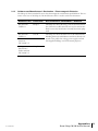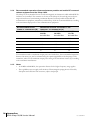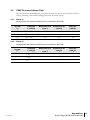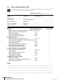
1
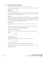
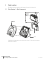
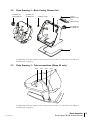
Table of Contents
1
Introduction .................................................................................................................... 3
1.1
2
About the iSleep 10/20 CPAP device ............................................................... 3
1.1.1
Function ........................................................................................... 3
1.1.2
Intended Use ................................................................................... 3
1.1.3
Design ............................................................................................. 3
1.1.4
Service Personnel’s Training Requirements .................................... 3
1.2
About this Manual ............................................................................................ 4
1.2.1
Scope .............................................................................................. 4
1.2.2
Intended Audience .......................................................................... 4
1.2.3
Icons ................................................................................................ 4
Service Instructions ........................................................................................................ 5
2.1
3
Introduction ...................................................................................................... 5
2.1.1
Safety Precautions ......................................................................... 5
2.1.2
Service Record ................................................................................ 5
2.1.3
Inspection Equipment and Tools ..................................................... 5
2.1.4
Replacement Parts .......................................................................... 6
2.2
Preparing for Inspection ................................................................................... 6
2.2.1
Initial Recording ............................................................................... 6
2.2.2
Inspecting the Markings .................................................................. 6
2.2.3
Information from the Patient/User ................................................... 6
2.2.4
Validity of the Documentation .......................................................... 7
2.3
External Inspection ........................................................................................... 7
2.3.1
Visual Inspection for External Damage and Wear ........................... 7
2.3.2
Checking the HA 01 Humidifier (if used, iSleep 20 only) ................. 7
2.3.3
Checking the Power Connection ..................................................... 7
2.3.4
Inspecting the Patient Circuit ........................................................... 7
2.3.5
Inspecting the CPAP Device Accessories ....................................... 7
2.3.6
Changing/Washing the Patient Filters ............................................. 7
2.3.7
Minimum Function Check ................................................................ 7
2.4
Internal Inspection ........................................................................................... 8
2.4.1
Cleaning the Inside of the CPAP device .......................................... 8
2.4.2
Checking the Cables ....................................................................... 8
2.4.3
Checking the Fastening of Components ......................................... 8
2.4.4
Checking the Power Supply ............................................................ 8
2.4.5
Reassembling the Casing ............................................................... 8
2.5
Complete Function Test. ................................................................................. 9
2.5.1
Checking the Pressure .................................................................... 9
2.5.2
Checking the Snooze Function (iSleep 20 only) ........................... 10
2.5.3
Adjusting the Settings for the Patient ............................................ 10
2.6
Electrical Safety Precautions ......................................................................... 11
Parts Location .............................................................................................................. 12
4
3.1
Parts Drawing 1 – Main Components ............................................................ 12
3.2
Parts Drawing 2 – Back Casing, Blower Unit ................................................. 13
3.3
Parts Drawing 3 – Tube connections (iSleep 20 only) ................................... 13
3.4
Parts Drawing 4 – Front Casing, Circuit Board .............................................. 14
3.5
Parts List for the iSleep 10 and iSleep 20 ...................................................... 14
Functional Diagrams .................................................................................................... 16
4.1
4.2
Doc. 004284 En X-1
Filtering/Smoothing Techniques .................................................................... 17
iSleep 10/20 Measuring and Display Devices ................................................ 17
Table of Contents 1
Breas iSleep 10/20 Service Manual
5
Opening the iSleep 10/20 and Replacing the Main Components ................................ 18
6
5.1
Opening the iSleep 10/20 .............................................................................. 18
5.2
Replacing the Complete Blower Assembly .................................................... 19
5.3
Replace the Circuit Board .............................................................................. 20
5.4
Replace the Clock Battery (iSleep 20 only) .................................................... 21
5.5
Replacing the Keypad .................................................................................... 22
Upgrade and Calibration .............................................................................................. 23
7
6.1
Firmware Upgrade ......................................................................................... 23
6.2
Pressure Calibration ....................................................................................... 23
Electronics ................................................................................................................... 24
8
7.1
Main Cabling Diagram .................................................................................... 24
7.2
Circuit Board Description ............................................................................... 25
Fault Tracing ................................................................................................................ 27
8.1
8.2
9
Fault Tracing Table ......................................................................................... 27
Function Failure Error Codes ......................................................................... 28
8.2.1
Reading the Error Codes ............................................................... 28
8.2.2
Error Code Tables ......................................................................... 28
Appendices .................................................................................................................. 32
9.1
9.2
9.3
9.4
9.5
Emission and Immunity Declaration ............................................................... 32
9.1.1
Guidance and Manufacturer's Declaration – Electromagnetic
Immunity ........................................................................................ 32
9.1.2
Notes ............................................................................................. 32
9.1.3
Guidance and Manufacturer's Declaration – Electromagnetic
Emission ........................................................................................ 33
9.1.4
Recommended separation distances between portable and
mobile RF communications equipment and the iSleep 10/20 ....... 34
9.1.5
Notes ............................................................................................. 34
CPAP Pressure/Volume Data ......................................................................... 35
9.2.1
iSleep 10 ....................................................................................... 35
9.2.2
iSleep 20 ....................................................................................... 35
Service Record iSleep 10/20 .......................................................................... 36
Returning Products to Breas .......................................................................... 37
Product Return Form– Breas iSleep 10/20 CPAP device .............................. 38
2 Table of Contents
Breas iSleep 10/20 Service Manual
Doc. 004284 En X-1
1
Introduction
This chapter gives an overview of the iSleep 10/20 CPAP device and this service manual.
WARNING!
This product must be repaired and/or modified in accordance with Breas service manuals, technical bulletins, and any special service instructions, by service technicians
that have been authorised after the Breas iSleep 10/20 service training, or have an
equivalent technical knowledge on medical respiratory devices.
Deviation from these service instructions may lead to risk of personal injury!
1.1
About the iSleep 10/20 CPAP device
1.1.1
Function
The iSleep 10/20 is a CPAP system that provides a continuous positive airway pressure. This can
prevent the user’s upper airways from collapsing and therefore avoid breathing problems associated
with airway collapse and obstruction.
The iSleep 20 has a pressure sensor that continuously monitors output pressure to the patient and
reference ambient pressure, so that the device automatically will compensate for altitude changes.
The internal memory of the iSleep 20 can be downloaded to a PC where you can view the patient
compliance data in the “Breas iSleep PC Software”.
1.1.2
Intended Use
For a detailed description on intended use, refer to the iSleep 10/20 Clinician's or User Manuals.
1.1.3
Design
The iSleep 10/20 is constructed around a blower assembly.
A microprocessor controls the speed of the blower motor by means of calculations based on the settings and pressure. iSleep 20 also monitors the reference ambient pressure, so that the device automatically will compensate for altitude changes.
1.1.4
Service Personnel’s Training Requirements
Service personnel working with the iSleep 10/20 should have medical/technical training and a good
knowledge of the construction and function of respiratory devices.
Always contact your Breas representative if you have any questions or if any training is
required.
Doc. 004284 En X-1
Introduction 3
Breas iSleep 10/20 Service Manual
1.2
About this Manual
1.2.1
Scope
This manual describes all the checks and the additional service actions for the iSleep 10/20. The
manual contains all the documentation that is required for the service of the CPAP device.
Breas Medical AB reserves the right to make changes to the products and/or the contents of this
manual without any prior notice.
1.2.2
Intended Audience
This service manual is intended for service technicians who have medical/technical training and
who have a good knowledge of the construction and function of respiratory devices.
Always contact your Breas representative if you have any questions or if any training is
required.
The service manual is not intended for clinical personnel or patients, who will find all the information
they need in the iSleep 10/20 Clinician's and User Manual.
1.2.3
Icons
In this manual, icons are used to highlight specific information. The meaning of each icon is
explained in the table below.
ICON
EXPLANATION
Warning!
Risk of death and serious personal injury.
Caution!
Risk of minor or moderate injury. Risk of equipment damage, loss of data,
extra work, or unexpected results.
Note
Information that may be valuable but is not of critical importance, tips.
Reference
Reference to other manuals with additional information on a specific topic.
4 Introduction
Breas iSleep 10/20 Service Manual
Doc. 004284 En X-1
2
Service Instructions
The iSleep 10/20 is designed to give users many years of trouble-free breathing assistance. The
iSleep 10/20 requires no periodic maintenance.
This chapter describes all the checks and additional service instructions for the iSleep 10/20.
WARNING!
This product must be repaired and/or modified in accordance with Breas service manuals, technical bulletins, and any special service instructions, by service technicians
that have been authorised after the Breas iSleep 10/20 service training, or have an
equivalent technical knowledge on medical respiratory devices.
Deviation from these service instructions may lead to risk of personal injury!
The patient and care provider should follow the checks that are described in the iSleep 10/20 User
and Clinician's Manual.
2.1
Introduction
Before you start a service, read the safety precautions and make sure you have a new service record
and all the necessary equipment, tools, and replacement parts at hand. It is important that any
peripheral equipment is checked at the same time as the services are carried out.
2.1.1
Safety Precautions
Follow the safety precautions below when working with the iSleep 10/20:
•
Do not work on the CPAP device with the casing removed and the power supply connected,
unless the instructions in this manual clearly says so.
•
Always use caution when working with the CPAP device connected to the mains and the
casing removed.
•
Do not use explosive gases and/or fluids near the CPAP device.
•
Make sure that all precautions to prevent electrostatic discharge (ESD) have been taken.
Follow all regulations regarding ESD.
The iSleep 10/20 User and Clinician's Manuals contains extended lists of safety precautions.
2.1.2
Service Record
The iSleep 10/20 service record is found in “Service Record iSleep 10/20” on page 36.
Copy the service record and use it for noting the service checks while performing the service.
2.1.3
Inspection Equipment and Tools
Before starting the service of the iSleep 10/20, make sure you have the following equipment at
hand:
•
Doc. 004284 En X-1
Pressure manometer (Thommen HM 28 digital manometer, Breas part no 001937, or
equivalent).
Service Instructions 5
Breas iSleep 10/20 Service Manual
2.1.4
•
Torx key TX 10.
•
iSleep to PC communication cable, Breas part no 003588.
•
iSleep/Vivo Service Software, available for download from Breas Extranet. Contact Breas
technical support for more information.
Replacement Parts
The following replacement parts should be available when servicing the CPAP device:
DESCRIPTION
PART NO.
Patient air filter, grey, washable
004154 (5 pcs)
Patient air filter, white, disposable
004153 (5 pcs)
If required:
Clock battery, CR 2032 (iSleep 20 only)
2.2
Preparing for Inspection
2.2.1
Initial Recording
002129
1 Copy a new service record (see “Service Record iSleep 10/20” on page 36).
2 Identify the iSleep 10 or iSleep 20.
3 Note the model and serial number and any inventory number on the service record.
4 Check any comments recorded on the previous service records.
5 Document the current patient settings.
6 Note the number of Total operating hours on the service record.
The operating hours are found at the “Device information” screen. Access the “Device information”
using the menu as described in the iSleep 10/20 Clinician’s Manual.
2.2.2
Inspecting the Markings
Make sure that all markings on the CPAP device’s information labels can be read:
2.2.3
•
Model description, serial number
•
Warning texts
•
Any inventory marking
•
Any other texts
Information from the Patient/User
Check the following with the patient:
•
Has the CPAP device functioned without any problems? If not, what were they?
•
How does the patient/care provider check the function of the CPAP device? How often?
•
How often is the filter replaced?
•
How many filters will be required before the next service?
•
Other observations?
6 Service Instructions
Breas iSleep 10/20 Service Manual
Doc. 004284 En X-1
2.2.4
Validity of the Documentation
1 Check the validity of the User or Clinician’s Manual enclosed with the CPAP device.
2 Check if any modification or upgrading of the CPAP device needs to be done at the same time
as the service.
2.3
External Inspection
2.3.1
Visual Inspection for External Damage and Wear
1 Clean the outside of the CPAP device using a mild soap solution.
2 Check for any visible damage to the casing and the other components.
3 Check that nothing has become loose.
4 Check that the rear lid is connected properly to the CPAP device.
2.3.2
Checking the HA 01 Humidifier (if used, iSleep 20 only)
1 Remove and open the HA 01.
2 Check that there is no visible damage.
3 Check that the water container is clean.
4 Check that the humidifier is connected properly to the CPAP device.
2.3.3
Checking the Power Connection
1 Check the plugs on the power cord, the cord itself, and the CPAP device’s power socket.
2 Check the power supply.
3 Inspect the external battery cable, if used.
2.3.4
Inspecting the Patient Circuit
Inspect the patient circuit and replace it if necessary.
2.3.5
Inspecting the CPAP Device Accessories
Check any other accessories that are used with the CPAP device.
2.3.6
Changing/Washing the Patient Filters
1 Change the white air filter (if used).
2 Change or wash the grey filter, if necessary.
2.3.7
Minimum Function Check
1 Connect the power cord.
2 Connect the patient circuit.
3 Start the CPAP device and make sure it operates normally.
Doc. 004284 En X-1
Service Instructions 7
Breas iSleep 10/20 Service Manual
2.4
Internal Inspection
Perform an internal inspection if having opened the iSleep 10/20.
Make sure to disconnect the power supply before opening the casing of the CPAP device.
2.4.1
Cleaning the Inside of the CPAP device
1 Open the casing. See “Opening the iSleep 10/20 and Replacing the Main Components” on
page 18 for instructions.
2 Remove any dirt or dust that has collected in the CPAP device casing.
3 Open the dark grey air channel top by
pulling it straight up and remove any dirt or
dust. Press the air channel back in place and
make sure it fits properly.
2.4.2
Checking the Cables
Inspect all the cables and their connectors. Check the front and rear panels to make sure that the
cables and the wires are not pinched or kinked.
2.4.3
Checking the Fastening of Components
Make sure that all the components, such as the circuit board, the connectors and the tubings
(iSleep 20 only) are securely fastened.
2.4.4
Checking the Power Supply
Make sure that the power connector is undamaged and that it is securely in place.
2.4.5
Reassembling the Casing
See “Opening the iSleep 10/20 and Replacing the Main Components” on page 18 for instructions.
8 Service Instructions
Breas iSleep 10/20 Service Manual
Doc. 004284 En X-1
2.5
Complete Function Test.
You can also perform the complete function test using the “iSleep/Vivo Service Software”.
To perform a complete function test, all tasks in this section needs to be completed in the
written order.
2.5.1
Checking the Pressure
1 Connect a 4 mm restrictor and a pressure manometer to the iSleep 10/20.
Leakage
4 mm hole
Pressure manometer
2 Adjust the settings as follows:
SETTING
VALUE
CPAP
4 cmH2O
3 Start the iSleep 10/20 and let it run for 30 minutes before the test.
4 Measure and check that the measured value for pressure is correct
iSleep 10 tolerance: ±5% of the maximum value and ±10% of the set value.
iSleep 20 tolerance: ±1 cmH2O.
5 Change the CPAP pressure to 10 cmH2O and repeat the measuring.
6 Change the CPAP pressure to 15 cmH2O and repeat the measuring.
7 Change the CPAP pressure to 20 cmH2O and repeat the measuring.
If the measured pressure values are not within tolerance, perform a pressure calibration/adjustment
of the CPAP device (see “Upgrade and Calibration” on page 23).
Doc. 004284 En X-1
Service Instructions 9
Breas iSleep 10/20 Service Manual
2.5.2
Checking the Snooze Function (iSleep 20 only)
1 Start the iSleep 20.
2 Shortly press the on/off button.
3 Check that the iSleep 20 reduces pressure and that the fan symbol
starts blinking.
4 Shortly press the on/off button.
5 Check that the iSleep 20 delivers the set pressure.
6 Shortly press the on/off button so that the snooze function activates.
7 Create a spontaneous breath.
8 Check that the iSleep 10/20 delivers the set pressure.
Read more about the Snooze function in the iSleep 20 Clinician’s manual.
2.5.3
Adjusting the Settings for the Patient
Adjust the settings as prescribed for the patient.
10 Service Instructions
Breas iSleep 10/20 Service Manual
Doc. 004284 En X-1
2.6
Electrical Safety Precautions
Electrical safety measurements must be made in accordance with IEC 601.
Use an automatic electrical safety tester to make the measurements. All tests must be performed in
accordance with class II type BF.
Supply Voltage
Note the power voltage reading.
The voltage must be noted at each service check, as the currents measured are directly in relation to
the supply voltage. This allows all measurements made on the same CPAP device to be compared
with measurements made on different occasions.
Insulation
The insulation resistance is measured using a 500 V DC power supply. The most suitable method is
to connect the plus lead to the two CPAP device power socket pins, and the minus lead to the casing
or the patient air connector. The measurements made during the delivery inspection can be used as
reference values for measurements made during future services. If no reference values are available,
the value for the insulation resistance should be >20 MΩ .
Leakage Currents
The leakage currents are measured at different parts of the CPAP device using an RC circuit to
earth.
Make the measurements partly at normal case (NC) and at the single fault condition (SFC). Reverse
the polarity of the power supply and note the highest value.
Leakage currents to earth must not exceed the stated limit values.
Leakage Currents from the Casing
The leakage current of the casing is measured at an unpainted point, for example, the head of a
screw.
Limit values:
NC <0.1 mA
SFC <0.5 mA
Break neutral for SFC.
Patient Leakage Currents
The patient leakage current is measured between the patient connector and earth.
Limit values:
NC <0.1 mA
SFC <0.5 mA
Break neutral for SFC.
Leakage Currents with Mains Power Supply at the Patient-connected Part
This test must be done using an automatic electrical safety tester with this function. See the safety
instructions for the tester.
Limit value: SFC <5 mA
Doc. 004284 En X-1
Service Instructions 11
Breas iSleep 10/20 Service Manual
3
Parts Location
This chapter contains part-number lists and drawings of the parts for the iSleep 10/20.
3.1
Parts Drawing 1 – Main Components
Accessory:
Humidifier
HA 01
(iSleep 20 only)
7 (iSleep 10)
8 (iSleep 20)
1
6-1 (11x)
For definitions of the part numbers, refer to the parts list in section 3.5, "Parts List for the iSleep 10
and iSleep 20", on page 14.
12 Parts Location
Breas iSleep 10/20 Service Manual
Doc. 004284 En X-1
3.2
Parts Drawing 2 – Back Casing, Blower Unit
9-2 (iSleep 10)
10-2 (iSleep 20)
12 (iSleep 10)
13 (iSleep 20)
5 (iSleep 10 only)
11-2 (2x)
2
(iSleep 20 only)
11-1
(iSleep 20 only)
9-1 (iSleep 10)
10-1 (iSleep 20)
4
For definitions of the part numbers, refer to the parts list in section 3.5, "Parts List for the iSleep 10
and iSleep 20", on page 14.
3.3
Parts Drawing 3 – Tube connections (iSleep 20 only)
10-3
10-4
10-6
10-5
For definitions of the part numbers, refer to the parts list in section 3.5, "Parts List for the iSleep 10
and iSleep 20", on page 14.
Doc. 004284 En X-1
Parts Location 13
Breas iSleep 10/20 Service Manual
3.4
Parts Drawing 4 – Front Casing, Circuit Board
7-5 (iSleep 10)
8-5 (iSleep 20)
7-1 (iSleep 10)
8-1 (iSleep 20)
7-6 (iSleep 10)
8-6 (iSleep 20)
7-2 (iSleep 10) 7-3 (iSleep 10)
8-2 (iSleep 20) 8-3 (iSleep 20)
14 (iSleep 10)
15 (iSleep 20)
3 (iSleep 20 only)
7-4 (iSleep 10)
8-4 (iSleep 20)
6-1 (11x)
For definitions of the part numbers, refer to the parts list in section 3.5, "Parts List for the iSleep 10
and iSleep 20", on page 14.
3.5
Parts List for the iSleep 10 and iSleep 20
The parts and service kits of the iSleep 10 and iSleep 20 are listed in the table below.
KIT NO.
DESCRIPTION
BREAS
PART NO.
AMOUNT
1
Air outlet patient assembly
004116
1
2
Suspension, noise box
004202
1
3
Battery CR2032 3 V (iSleep 20 only)
002129
1
4
Friction pad
003692
1
5
Plug RJ45-8 (iSleep 10 only)
003733
1
6
Screw kit – iSleep
004296
6-1
Screw STS-T30x8 FZB
7
Case front kit - iSleep 10
7-1
Case front
1
7-2
Window “iSleep 10“
1
7-3
Keypad
1
14 Parts Location
Breas iSleep 10/20 Service Manual
11
004295
Doc. 004284 En X-1
BREAS
PART NO.
KIT NO.
DESCRIPTION
7-4
Air channel
1
7-5
Logotype “iSleep“
1
7-6
Insulation air channel
1
8
Case front kit - iSleep 20
8-1
Case front
1
8-2
Window “iSleep 20“
1
8-3
Keypad
1
8-4
Air channel
1
8-5
Logotype “iSleep“
1
8-6
Insulation air channel
1
9
Tube kit - iSleep 10
9-1
Tube outlet
1
9-2
Tube inlet
1
10
Tube kit - iSleep 20
10-1
Tube outlet
1
10-2
Tube inlet
1
10-3
Silicone tube - Yellow, short
1
10-4
Silicone tube - Yellow, long
1
10-5
Silicone tube - Pink
1
10-6
Barbed tube connection
1
11
Lock device kit - iSleep 20
11-1
Lock device
1
11-2
Spring conical
2
12
Blower assembly - iSleep 10
004225
1
13
Blower assembly - iSleep 20
004226
1
10-3
Silicone tube - Yellow, short
1
10-4
Silicone tube - Yellow, long
1
10-5
Silicone tube - Pink
1
10-6
Barbed tube connection
1
14
CPU board - iSleep 10
003771
1
15
CPU board - iSleep 20
003767
1
Doc. 004284 En X-1
AMOUNT
004287
004368
004288
004289
Parts Location 15
Breas iSleep 10/20 Service Manual
4
Functional Diagrams
This chapter contains a diagram of the pneumatic system of the CPAP device and a block diagram
of the iSleep 10/20’s functions.
The functional block diagram below shows how the electronics and pneumatics are designed and
how they are connected to the other components.
Display
controller
LCD
Power
control
DC inlet
Buttons
Control
logic
LED (iSleep 20 only)
Com port
analog out
Blower
amplifier
Pressure
transducer
(iSleep 20 only)
4
2
3
5
9
Pink
6
7
1
8
Electrical connection
Pneumatic connection
16 Functional Diagrams
Breas iSleep 10/20 Service Manual
Doc. 004284 En X-1
The table below describes the components of the pneumatic diagram.
4.1
4.2
NO.
DESCRIPTION
1
Air inlet filter
2
Blower
3
Silencer box
4
iSleep 10/20 casing
5
Pressure sensor (iSleep 20 only)
6
Humidifier (optional, iSleep 20 only)
7
Patient tube
8
Leak holes
9
Mask
Filtering/Smoothing Techniques
FUNCTION
TECHNIQUE DESCRIPTION
Pressure
Low pass average time constant 16 ms
iSleep 10/20 Measuring and Display Devices
SENSING
POSITION
DEVICE
PURPOSE
TYPE
RANGE
RESOLUTION
ACCURACY
Pressure
sensing
Regulate
pressure
Differential
to ambient
-10 to
+60 cmH2O
0.1 cmH2O
±0.1% FSS
Air outlet
of iSleep
Pressure
display
Indicate patient
pressure
LCD
0 to 20 cmH2O
0.1 cmH2O
±0.5 cmH2O
Air outlet
of iSleep
Doc. 004284 En X-1
Functional Diagrams 17
Breas iSleep 10/20 Service Manual
5
Opening the iSleep 10/20 and Replacing the Main
Components
Make sure to disconnect the power supply before removing the casing of the CPAP device.
5.1
Opening the iSleep 10/20
• Before closing the iSleep 10/20, perform an internal inspection, see “Internal Inspection” on
page 8.
• Always perform a complete function test after reassembling the iSleep 10/20, see “Complete
Function Test.” on page 9.
• Always perform an electrical safety test after reassembling the iSleep 10/20, see “Electrical
Safety Precautions” on page 11.
• Make sure that the iSleep 10/20 is placed on a non-scratching surface.
• Make sure that the tubes are not pinched or kinked when closing the iSleep 20.
1 Remove the rear lid or the HA 01 humidifier (if used, iSleep 20 only).
2 Remove the six screws for the casing.
18 Opening the iSleep 10/20 and Replacing the Main Components
Breas iSleep 10/20 Service Manual
Doc. 004284 En X-1
3 Lift the back casing straight up and tilt it
backwards onto the table.
4 Reassemble in reverse order.
Make sure that the inlet and outlet tubes are
properly fitted.
• The outlet tube should be pointing slightly
upwards when fitted to the back casing.
5.2
Replacing the Complete Blower Assembly
1 Open the iSleep 10/20 as in section 5.1.
2 Disconnect the cabling for the BLDC
motor control.
Doc. 004284 En X-1
Opening the iSleep 10/20 and Replacing the Main Components 19
Breas iSleep 10/20 Service Manual
3 Disconnect the pressure sensing tube
(iSleep 20 only).
4 Lift the blower assembly straight up.
Remove the old pressure sensing tube from the
circuit board and connect the one that is
attached to the blower assembly (iSleep 20
only).
5 Reassemble in reverse order.
5.3
Replace the Circuit Board
The iSleep 10/20 serial number needs to be programmed into the new circuit board.
You need the “iSleep/Vivo Service Software” to program the circuit board with the correct serial number
after replacement.
1 Open the iSleep 10/20 as in section 5.1.
2 Disconnect the cabling for the humidifier
(iSleep 20 only).
20 Opening the iSleep 10/20 and Replacing the Main Components
Breas iSleep 10/20 Service Manual
Doc. 004284 En X-1
3 Remove the five screws for the circuit
board.
4 Lift the circuit board by it’s edges straight
up.
5 Reassemble in reverse order.
Remove the pressure sensing tube from the old circuit board and attach it to the new one
(iSleep 20 only).
5.4
Replace the Clock Battery (iSleep 20 only)
1 Open the iSleep 20 as in section 5.1 and move the blower assembly from the circuit board so
you can access the clock battery.
2 Remove the clock battery by pulling it
straight up. Press a new clock battery into
place.
+
Make sure that the new battery is not handled with bare hands.
3 Reassemble in reverse order.
Doc. 004284 En X-1
Opening the iSleep 10/20 and Replacing the Main Components 21
Breas iSleep 10/20 Service Manual
5.5
Replacing the Keypad
1 Remove the circuit board as in section 5.3.
2 Remove and replace the keypad.
3 Reassemble in reverse order.
22 Opening the iSleep 10/20 and Replacing the Main Components
Breas iSleep 10/20 Service Manual
Doc. 004284 En X-1
6
Upgrade and Calibration
6.1
Firmware Upgrade
To upgrade the iSleep 10/20 firmware you need the “Firmware Upgrade Tool iSleep/Vivo” available for
download from Breas Extranet. Contact Breas technical support for more information.
6.2
Pressure Calibration (iSleep 20 only)
To calibrate the iSleep 20 you need the “iSleep/Vivo Service Software” available for download from Breas
Extranet. Contact Breas technical support for more information.
Doc. 004284 En X-1
Upgrade and Calibration 23
Breas iSleep 10/20 Service Manual
7
Electronics
Always perform a complete function test (see section 2.5 on page 9) if you have opened the
iSleep 10/20.
The electronics, optics, mechanics, and pneumatics of the iSleep 10/20 are integrated. To understand fully the electronics of the iSleep 10/20, you must know how to use the CPAP device, study
the pneumatic diagram and acquaint yourself with the mechanical construction.
7.1
Main Cabling Diagram
The diagram below illustrates the main cabling of the iSleep 10/20.
Humidifier
X7
(iSleep 20 only)
Blower
assembly
Brown
Yellow
Purple
LCD
CPU
1
X8
DC inlet
24 Electronics
Breas iSleep 10/20 Service Manual
X9
Doc. 004284 En X-1
7.2
Circuit Board Description
The diagram below is an overview of the circuit board
RJ45
connector
DC inlet
Buttons
Power
control
Reset
Serial
interface
Display
CPU
LEDs
(iSleep 20 only)
Buzzer
Real time
crystal
(iSleep 20 only)
BLDC
amplifier
Clock battery
(iSleep 20 only)
Pressure sensor
(iSleep 20 only)
Motor
connector
Humidifier
interface
(iSleep 20 only)
Humidifier
connector
(iSleep 20 only)
Power Control
There is one power input (+24 V DC). The CPU board contains a voltage regulator for 5 V and
iSleep 20 also has a 8 V regulator.
Battery (iSleep 20 only)
A battery is used to keep the real time clock alive when the iSleep 20 is not powered.
CPU (Central Processing Unit)
The processing core of the main unit is a M30281FAHP microcontroller.
The main processor has a supply voltage of 5 V and is not operating when the iSleep 10/20 is not
powered (apart from the clock function on iSleep 20 which is powered by the clock battery).
Display
The display used is a segment type and have a visible area of approximately 60 x 20 mm.
Buzzer (iSleep 20 only)
The buzzer is triggered by software or hardware.
Doc. 004284 En X-1
Electronics 25
Breas iSleep 10/20 Service Manual
Pressure Sensor (iSleep 20 only)
The iSleep 20 is equipped with a pressure sensor. The processor supervise the actual pressure and
have the availability to regulate the speed of the motor to attain a correct pressure.
Humidifier Interface (iSleep 20 only)
The iSleep 20 can be equipped with an integrated humidifier, HA 01.
The HA01 humidifier consumes 40 W when attached to the iSleep 20.
The power to the HA 01 humidifier is controlled from the main CPU via a transistor.
The other two signals in the interface beside power and ground are an analogue temperature signal
from the HA 01 humidifier and a control signal to the HA 01 humidifier.
Serial Interface
To communicate with a PC, the iSleep 10/20 uses a RS232 interface.
26 Electronics
Breas iSleep 10/20 Service Manual
Doc. 004284 En X-1
8
Fault Tracing
Always perform a complete function test (see section 2.5 on page 9) if you have opened the
iSleep 10/20.
This chapter contains a fault-tracing table and a table of error codes to use when troubleshooting
the iSleep 10/20.
8.1
Fault Tracing Table
If the iSleep 10/20 does not work properly try to identify the problem in the table below. Check the
possible causes and carry out the suggested remedial actions.
SYMPTOM
POSSIBLE CAUSE
REMEDIAL ACTION
SEE REF.
The iSleep 10/20
does not start
The power cord is not
properly connected.
Connect the power cord.
6.3 in
iSleep 10/20
Clinician’s
manual
The DC fuse on the circuit
board has blown.
Replace the circuit board and
check the power supply.
5.3, p.20
The power supply is not
24 V DC.
Check the power transformer.
External battery discharged.
Charge external battery.
The external battery cable is
not connected properly or is
faulty.
1 Connect the cable.
Battery polarity faulty.
May be the case if fuse blows
immediately after connecting
to external battery cable.
Check polarity.
External leaks from patient
circuit or nasal mask.
Check the tubes, connectors
and mask for leaks.
2.3, p.7
Internal leaks from tubes,
humidifier or air channels.
Check the tubes, air channels
and the humidifier.
2.4, p.8
Air inlet is blocked.
Check filter and air channels.
Pressure indicator
shows no pressure
reading.
The internal supply tube is
blocked or loose.
Check the tubes.
2.4, p.8
The circuit board is faulty.
Replace the circuit board.
5.3, p.20
The clock resets
when having disconnected the
power supply.
(iSleep 20 only)
The clock battery discharged.
Replace the clock battery.
5.4, p.21
The iSleep 10/20
does not give the
adequate pressure.
Doc. 004284 En X-1
2 Measure the voltage.
3 Replace the cable if faulty.
Fault Tracing 27
Breas iSleep 10/20 Service Manual
8.2
Function Failure Error Codes
8.2.1
Reading the Error Codes
When an internal function failure occurs a four digit error code will be stored in the iSleep 10/20
error log. The function failure will also generate a message shown on the display.
You need the “iSleep/Vivo Service Software” to access the error log.
8.2.2
Error Code Tables
Error Codes Shown on the Display
The table below lists the error codes and the corresponding text that can be shown on the LCD display. The problem is explained together with the action that is necessary to correct the problem, see
also “Internal Error Codes, Not Shown on the Display (iSleep 20 only)” on page 29.
If more than one action is listed, the actions should be performed in the order in which they are
listed. For example, if action no. 1 does not solve the problem you should continue with action no.
2, and so on.
See “Opening the iSleep 10/20 and Replacing the Main Components” on page 18 for information
about how to replace the circuit board.
ERROR
CODE
20
TEXT ON LCD DISPLAY
PROBLEM
ACTION
Er20
Internal function failure.
1 Restart the iSleep 10/20 by dis-
connecting and reconnecting the
power supply.
2 Perform an internal inspection
3 Replace the circuit board or send
the iSleep 10/20 for service.
21
Er21
Power supply voltage out
of range.
Check the power supply.
28
Er28
Humidifier not heating
(iSleep 20 only).
1 Replace the HA 01 humidifier.
2 Perform an internal inspection.
3 Replace the circuit board or send
the iSleep 10/20 for service.
29
Er29
Humidifier temperature
too high.
(iSleep 20 only).
Replace the HA 01 humidifier.
30
Er30
Internal temperature too
high.
1 Disconnect the iSleep 10/20
28 Fault Tracing
Breas iSleep 10/20 Service Manual
from the power supply, let the device
cool off and restart.
2 Check the ambient temperature.
3 Replace the circuit board or send
the iSleep 10/20 for service.
Doc. 004284 En X-1
ERROR
CODE
61
TEXT ON LCD DISPLAY
PROBLEM
ACTION
Er61
Invalid settings.
Settings set to default
values.
1 Restart the iSleep 10/20 by dis-
connecting and reconnecting the
power supply.
2 Replace the circuit board or send
the iSleep 10/20 for service.
Internal Error Codes, Not Shown on the Display (iSleep 20 only)
If a function failure listed in the table below occurs the four-digit error code is stored in the iSleep 20
error log and one of the messages listed above is shown on the display.
You need the “iSleep/Vivo Service Software” to access the error log.
ERROR
PROBLEM
ERROR CODE ON DISPLAY
1000
Flash memory error
Er20
1001
Checksum error when data was read back
Er20
1002
Error when tried to write checksum to flash
Er20
1003
Checksum error when tried to read parameters
Er20
1004
Failed to write data to flash
Er20
1050
Critical flash error
Er20
1051
Flash has failed to be initiated
Er20
1052
Flash has failed to erase memory to write parameters
Er20
1053
Failed to write parameters to flash
Er20
1054
Failed to erase a block in flash
Er20
1055
Failed to erase a block in flash
Er20
1056
Failed to write log data to flash
Er20
1057
Flash memory contains no data
Er20
1058
Flash memory is full
Er20
1059
Flash data is corrupt
Er20
1100-1199
LCD error
Er20
1200-1299
Initiate error
Er20
1300
Selftest error
Er20
1301
Humidifier temperature is not rising
Er28
1350
Critical selftest error
Er20
1351
A/D channel error
Er20
1352
RAM error
Er20
CODE
Doc. 004284 En X-1
Fault Tracing 29
Breas iSleep 10/20 Service Manual
ERROR
PROBLEM
ERROR CODE ON DISPLAY
1353
FLASH error
Er20
1354
Timer error
Er20
1355
Motor voltage out of range at start up
Er20
1356
Motor current out of range at start up
Er20
1357
Motor phase
Er20
1358
Motor phase
Er20
1359
Motor phase
Er20
1360
Pressure to high
Er20
1361
Motor current too high when operating
Er20
1362
VCC too high
Er21
1363
VCC too low
Er21
1364
Motor sense too high in stand by mode
Er20
1365
CPU voltage too high
Er20
1366
CPU voltage too low
Er20
1367
Adapter sense too low
Er20
1368
VCC-Adapter voltage is out of range
Er20
1369
Internal temperature too high
Er30
1370
Internal temperature too low
Er20
1371
Adapter ground potential too low
Er20
1372
Adapter ground potential too high
Er20
1373
Adapter out voltage too high in stand by mode
Er20
1374
Pressure offset compensation out of range
Er20
1376
Humidifier temperature too high
Er29
1377
Inverse copy of parameters is corrupt
Er20
1378
Inverse copy of time is corrupt
Er20
1379
Inverse copy of date is corrupt
Er20
1380
Error buffer has been overrunned
Er20
1400-1499
Log error
Er20
1651
Set pressure out of range
Er61
1652
Tried to set pressure above 20 cmH2O
Er61
1653
Set pressure out of range
Er61
1654
Start ramp pressure out of range
Er61
1655
Set humidifier out of range
Er61
CODE
30 Fault Tracing
Breas iSleep 10/20 Service Manual
Doc. 004284 En X-1
ERROR
PROBLEM
ERROR CODE ON DISPLAY
1666
An old set of parameters is restored
Er61
1667
Parameters has been set to default
Er61
1700-1799
MMI error
Er20
1850
Motor fault
Er20
1851
High RPM, might generate too high pressure
Er20
2000-2099
Errors codes used for testing only
Er20
CODE
Doc. 004284 En X-1
Fault Tracing 31
Breas iSleep 10/20 Service Manual
9
Appendices
9.1
Emission and Immunity Declaration
According to IEC 60601-1-2(2001) + A1(2004).
9.1.1
Guidance and Manufacturer's Declaration – Electromagnetic Immunity
The iSleep 10/20 are intended for use in the electromagnetic environment specified below. The customer or the user of the iSleep 10/20 should assure that it is used in such an environment.
Portable and mobile RF (radio frequency) communications equipment should not be used no closer
to any part of the iSleep 10/20, including cables, than the recommended separation distance calculated from the equation applicable to the frequency of the transmitter.
IMMUNITY
IEC 60601
COMPLIANCE
TEST
TEST LEVEL
LEVEL
Conducted RF
IEC 61000-4-6
3 Vrms
150 kHz to
80 MHz
10 V
d= 0,27*√P m
Radiated RF
IEC 61000-4-3
3 V/m
80 MHz to
2.5 GHz
10 V/m
d= 0.27*√P m at 80 MHz to 800 MHz
d= 0.54*√P m at 800 MHz to 2.5 GHz
Equation description: P is the maximum output
power rating of the transmitter in watts (W) according
to the transmitter manufacturer and d is the recommended separation distance in metres (m).
Field strengths from fixed RF transmitters, as determined by an electromagnetic site surveya, should be
less than the compliance level in each frequency
rangeb.
Interference may occur in the vicinity of
equipment marked with this symbol.
9.1.2
RECOMMENDED SEPARATION DISTANCE
Notes
•
At 80 MHz and 800 MHz, the higher frequency range applies.
•
These guidelines may not apply in all situations. Electromagnetic propagation is affected by
absorption and reflection from structures, objects and people.
a) Field strengths from fixed transmitters, such as base stations for radio (cellular/cordless) telephones and land mobile radios, amateur radio, AM and FM radio broadcast and TV broadcast cannot be predicted theoretically with accuracy. To assess the electromagnetic environment due to fixed
RF transmitters, an electromagnetic site survey should be considered. If the measured field strength
in the location in which the iSleep 10/20 is used exceeds the applicable RF compliance level above,
the iSleep 10/20 should be observed to verify normal operation. If abnormal performance is
observed, additional measures may be necessary, such as reorienting or relocating the iSleep 10/20.
b) Over the frequency range 150 kHz to 80 MHz, field strengths should be less than 10 V/m.
32 Appendices
Breas iSleep 10/20 Service Manual
Doc. 004284 En X-1
9.1.3
Guidance and Manufacturer's Declaration – Electromagnetic Emission
The iSleep 10/20 are intended for use in the electromagnetic environment specified below. The customer or the user of the iSleep 10/20 should assure that it is used in such an environment.
Doc. 004284 En X-1
EMISSIONS TEST
COMPLIANCE
ELECTROMAGNETIC ENVIRONMENT – GUIDANCE
RF emissions
CISPR 11
Group 1
The iSleep 10/20 use RF energy only for its internal function. Therefore, its RF emissions are very low and are not
likely to cause any interference in nearby electronic equipment.
RF emissions
CISPR 11
Class B
Harmonic
emissions
IEC 61000-3-2
Class A
The iSleep 10/20 are suitable for use in all establishments,
including domestic establishments and those directly connected to the public low-voltage power supply network
that supplies buildings used for domestic purposes.
Voltage
fluctuations/
flicker emission
IEC 61000-3-3
Complies
Appendices 33
Breas iSleep 10/20 Service Manual
9.1.4
Recommended separation distances between portable and mobile RF communications equipment and the iSleep 10/20
The iSleep 10/20 are intended for use in an electromagnetic environment in which radiated RF disturbances are controlled. The customer or the user of the iSleep 10/20 can help prevent electromagnetic interference by maintaining a minimum distance between portable and mobile RF
communications equipment (transmitters) and the iSleep 10/20 as recommended below, according
to the maximum output power of the communications equipment.
RATED MAXIMUM OUTPUT
POWER OF TRANSMITTER
(W)
SEPARATION DISTANCE ACCORDING TO THE
FREQUENCY OF TRANSMITTER (M)
150 kHz to
80 MHz
d= 0.27*√P m
80 MHz to
800 MHz
d= 0.27*√P m
800 MHz to
2.5 GHz
d= 0.54*√P m
0.01
0.03
0.03
0.05
0.1
0.08
0.08
0.17
1
0.27
0.27
0.54
10
0.85
0.85
1.7
100
2.7
2.7
5.4
For transmitters rated at a maximum output power not listed above, the recommended separation
distance d in metres (m) can be estimated using the equation applicable to the frequency of the
transmitter, where P is the maximum output power rating of the transmitter in watts (W) according
to the transmitter manufacturer.
9.1.5
Notes
•
At 80 MHz and 800 MHz, the separation distance for the higher frequency range applies.
•
These guidelines may not apply in all situations. Electromagnetic propagation is affected by
absorption and reflection from structures, objects and people.
34 Appendices
Breas iSleep 10/20 Service Manual
Doc. 004284 En X-1
9.2
CPAP Pressure/Volume Data
The values have been produced during a test where the iSleep 10/20 have been attached to a 0.5 litre
test lung simulating a sinusoidal breathing pattern with 20 breaths/minute.
9.2.1
iSleep 10
Average Value and Variation of Air Pressure at the Patient Air Outlet
PRESSURE
P (CMH2O)
VOLUME
(L)
9.2.2
BREATHING RATE
-1
F (MIN )
AVERAGE VALUE
(CMH2O)
VARIATION
(CMH2O)
0.5
1
20
7.2
5.2
0.5
2
/3 pmax = 13
20
14.2
7.3
0.5
Pmax = 20.0
20
21.8
9.2
/3 pmax = 6.5
iSleep 20
Average Value and Variation of Air Pressure at the Patient Air Outlet
BREATHING RATE
-1
F (MIN )
AVERAGE VALUE
(CMH2O)
VARIATION
(CMH2O)
20
6.99
2.48
0.5
1/ p
3 max = 6.5
2/ p
3 max = 13
20
13.35
1.14
0.5
Pmax = 20.0
20
20.26
1.42
VOLUME
(L)
0.5
Doc. 004284 En X-1
PRESSURE
P (CMH2O)
Appendices 35
Breas iSleep 10/20 Service Manual
9.3
Service Record iSleep 10/20
Use a photocopy of this service record for the inspections described in “Service Instructions” on
page 5. Use the next page for comments and notes.
Service record no._________________
Model:..................................
Serial no. ..............
Inventory no. ....................................
Accessories: ...............................................................................................................................
Delivery date: .......................
Total operating hours:..............................................................
Service started: ....................
Signature:................................................................................
Service completed:...............
Signature:................................................................................
Product returned:..................
Signature:................................................................................
General
See instruction ref.
Open new service record and identify CPAP device
Note number of total operating hours
Check all markings
Check information from user
Check validity of documentation
Check OK
2.2.1, p.6
2.2.1
2.2.2
2.2.3
2.2.4
........
........
........
........
........
2.3.1, p.7
2.3.2
2.3.3
2.3.4
2.3.5
2.3.6
2.3.7
........
........
........
........
........
........
........
2.4.1, p.8
2.4.2
2.4.3
2.4.4
2.4.5
........
........
........
........
........
2.5.1
2.5.2
2.5.3
........
........
........
External Checks
Inspect for external damage and wear
Check the HA 01 humidifier (if used, iSleep 20 only)
Check power connection
Inspect patient circuit
Inspect the CPAP device accessories
Change/wash the patient filters
Perform minimum function check
Internal Checks (when required)
Clean inside of the CPAP device
Check cabling
Check fastening of components
Check the power supply
Reassemble the casing
Complete Function Check
Check the pressure
Check the snooze function (iSleep 20 only)
Adjust settings for patient
Notes
_________________________________________________________________________
_________________________________________________________________________
_________________________________________________________________________
_________________________________________________________________________
36 Appendices
Breas iSleep 10/20 Service Manual
Doc. 004284 En X-1
9.4
Returning Products to Breas
You may need to return the CPAP device, components or accessories to Breas Medical AB for service, warranty, upgrade or repair. In this case, follow the instructions below to ensure that the correct
action is taken to avoid unnecessary delays.
1 Pack the product in its original packing. If this is not available, pack the product in packaging
suitable for the transportation to Breas Medical AB.
2 Take a photocopy of the delivery report on the next page.
3 Fill out the delivery report and pack it together with the product to be returned.
Product damage caused by poor packaging or during transportation is not covered by the
factory warranty.
Doc. 004284 En X-1
Appendices 37
Breas iSleep 10/20 Service Manual
9.5
Product Return Form– Breas iSleep 10/20 CPAP device
Breas ref. no.:...............................
Customer information
Customer name:.................................................................................................................
Address: .............................................................................................................................
.............................................................................................................................................
Phone:.................................................................................................................................
Reference person: .....................................................
Customer ref. no.:....................
Product information
Model: ..........................
Serial no.:.........................
Total operating hours:.............
Error – Complaint – Accessories
.............................................................................................................................................
.............................................................................................................................................
.............................................................................................................................................
.............................................................................................................................................
.............................................................................................................................................
.............................................................................................................................................
.............................................................................................................................................
.............................................................................................................................................
.............................................................................................................................................
.............................................................................................................................................
.............................................................................................................................................
.............................................................................................................................................
.............................................................................................................................................
.............................................................................................................................................
38 Appendices
Breas iSleep 10/20 Service Manual
Doc. 004284 En X-1