1
Congratulations, you have purchased the finest exhaust system
for your motorcycle on the market. Your Vance & Hines exhaust
system is designed and crafted for maximum performance, a
perfect fit, a great sound and unbeatable style. Please follow the
installation instructions below and if you have any questions,
please call our technical support line at (562) 926-5291.
Attention installer (if other than owner), please forward this
instruction sheet to the owner of this product. These instructions
contain valuable information to the end user.
TOOLS
REQUIRED
Flat blade screwdriver
#3 Phillips Head
Snapring pliers
5/16” Nutdriver
1/2”, 9/16” &
14mm Combination
wrenches
3/16” & 5/16” Allen wrench
3/8” Ratchet, extensions
1/2” & 9/16” Sockets
3/4” Deep Socket
T45 & T50 Torx wrenches
READ ALL INSTRUCTIONS BEFORE BEGINNING INSTALLATION
1.
STOCK EXHAUST
SYSTEM REMOVAL
MOR POWER : LESS NOISE
HARLEY-DAVIDSON® SOFTAIL
BIG SHOTS LONG
INSTALLATION INSTRUCTIONS
PART# 17823
2.
3.
4.
5.
6
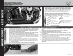
Remove the seat, locate the rear O2 sensor connector and unplug the sensor
from the harness. Remove the battery and feed the sensor cable end through
the frame. NOTE: Pay attention to wire routing for re-installation. Refer to
service manual for proper battery removal.
Unplug the front sensor (located behind the rectifier) from harness and feed
the end of the wire through the frame, freeing it from motorcycle.
On FLSTC, FLSTF, and FLSTN (floorboard models), loosen the right hand floor
board mounting bolts to gain clearance for exhaust removal and installation.
If equipped, unbolt the carriage bolt and clamp attached to the bracket under
the right side transmission cover.
On FLSTF, FXS and FLSTN (foot peg models), you will need to remove the
right side passenger footpeg and hanger, as this is attached to the exhaust
mount bracket. Replace the passenger foot peg assembly using the 3/8” x 2
1/2” Allen bolt (supplied).
Loosen the heat shield clamps on both front and rear exhaust pipes.
FIGURE 1
8.
9.
10.
11.
12.
13.
14.
Remove the two mounting nuts from each head pipe, located at the cylinder
head.
Remove the nuts attaching the exhaust mount bracket to the frame.
Remove the entire exhaust system and set it aside.
Remove the two lower mounting studs from the frame using the 3/4” deep
socket (Figure 1).
If equipped, remove the bracket from under the right side transmission cover.
Using 14mm wrench, carefully remove the O2 sensors from the stock header
and save them for re-use with the new system.
Carefully remove exhaust port flanges and circlips from the stock exhaust
system using snapring pliers. NOTE: Replace bent or damaged circlips.
Remove stock exhaust gaskets and replace them with the supplied exhaust
gaskets NOTE: Replacement gaskets HD Screaming eagle #17048-98 or
equivalent.
FIGURE 2
Remove studs
Page 1 of 4
7.
Mark mounting
clip locations
D602IN Rev. 1.1
FIGURE 3
FIGURE 4
FIGURE 5
FIGURE 6
Install circlips
and flanges
Slide header into heat shields
VANCE & HINES EXHAUST
SYSTEM INSTALLATION
1.
2.
3.
4.
5.
6.
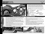
Remove header and heat shields from protective packaging. NOTE: Removal
of end cap may be required. Place each heat shield on a non-abrasive
surface such as a blanket or carpet. Using a felt tip pen, mark outside edge
of each heat shield to show location of mounting clips that hose clamps will
loop through (Figure 2).
Slide header into heat shields tail end first, engaging end caps (Figure 3).
Install end caps (if removal was necessary) into tail end of each heat shield
engaging head pipe and heat shield. Align mounting hole with end cap
hole. Install and tighten 1/4”-20 button head screws. NOTE: Removable
thread locking compound is recommended.
Install each hose clamp (supplied) by feeding tail end of clamps into heat
shield clips. Take note of location of clamp screw head direction (Figure 2 &
4). Screw head must be accessible when system is installed on motorcycle for
adjustment purposes. Align end tips evenly and tighten hose clamps.
Apply a small amount of anti-seize compound to the threads of the O2
sensors removed from the stock head pipes and install them into the new
head pipes. NOTE: Install O2 sensor with gray connector (short) in the
front head pipe and the O2 sensor with black connector (long) into rear
head pipe. Be careful not to get anti-seize on sensor tip, it may affect sensor
function.
Install circlips and flanges from stock system onto the new head pipe
(Figure 5).
7.
8.
9.
10.
11.
12.
13.
14.
Install Bracket
Attach mounting bracket (Stamped 331-P)(supplied) using four 5/16“x5/8”
flange bolts and two nut plates (supplied). Slide nut plates inside brackets
that are welded to the backside of each muffler (Figure 6). Leave them loose
at this time. Use this procedure for both upper and lower muffler mounting
positions.
Install complete assembly into exhaust ports (rear port first). Use stock flange
nuts, do not tighten at this time. Install exhaust bracket to motorcycle frame
rail using two 3/8”x3/4” flange bolts (supplied). Do not tighten at this time.
Tighten cylinder port exhaust flange nuts on front and rear cylinders. Now
tighten the 5/16”x5/8” flange bolts (supplied) and the 3/8”x3/4” flange bolts
(supplied) attaching the bracket to the frame.
Feed connector for the rear O2 sensor (Black) through the frame and under
the seat. Re-install battery, plug the sensor into the stock wiring connector.
Feed connector for the front O2 (Gray) sensor through the frame and into
the holder on the frame behind the rectifier. Plug the sensor into the stock
wiring connector.
Re-tighten floor board mounting bolts on models so equipped.
Be sure to tighten all hardware before starting motorcycle.
After installation and before starting the motorcycle, completely clean pipes
and mufflers with warm soapy water and a clean soft cloth that will not
leave a residue. NOTE: Any residue, oil, or fingerprints will stain the chrome
when the metal heats up.
EXHAUST CARE - HELPFUL HINTS TO AVOID DISCOLORATION OF EXHAUST SYSTEM
1.
When installing a new set of chrome pipes, make sure your hands are clean and free of oil.
After installation, thoroughly clean pipes with warm soapy water and a soft cloth. Dry with
clean towel to remove any residue (chrome wax / polish, glass cleaner, alcohol, ammonia,
etc...) before starting the motorcycle.
2.
3.
4.
Avoid long periods of idling as this can cause discoloration.
Intake leaks can cause the engine to run lean and overheat, this could lead to discoloration.
Make sure there are no exhaust leaks at the junction of the exhaust pipes and cylinder head.
We recommend replacing gaskets if they are worn.
FUEL MANAGEMENT:
Take the guess work out of fuel injection with Fuelpak Fuel
Management. Contact your local dealer or call (562) 921-0071
to order. Visit fuelpakfi.com for more information.
Fuelpak is intended for racing or off-highway use only, and is
not legal for sale or use in California on pollution-controlled
vehicles.
QUIET
BAFFLE
VANCE & HINES OPTIONAL ACCESSORIES
FUELPAK
MOR POWER : LESS NOISE
Arrows indicate screw head direction
Quiet baffle P/N 21869 is available for this
system. The quiet baffle will lower the sound
level by 2-3db on average.Contact your local
dealer to order.
PLEASE NOTE: Every effort is made for Vance & Hines Exhaust Systems to provide improved cornering clearance. However, due to design and space limitations on some motorcycle models, ground and
cornering clearance may not be improved and in some cases may be reduced. Be sure to follow proper installation instructions.
Page 2 of 4
D602IN Rev. 1.1
HARLEY-DAVIDSON® SOFTAIL
BIG SHOTS LONG
INSTALLATION INSTRUCTIONS
PART# 17823
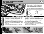
Nut plate x 2
#20 Hose clamps x 7
ALL PARTS SHOWN ARE ACTUAL SIZE
MOR POWER : LESS NOISE
PACKING LIST
Exhaust Gaskets x 2
3/8” x 2-1/2” Allen bolt x 1
3/8” x 3/4” Flange bolts x 2
5/16” x 5/8” Flange bolts x 4
PARTS NOT SHOWN:
331-P Bracket x1
D466FC Head pipe x1
D465HC Front heat shield x1
D466HC Rear heat shield x1
WARRANTY
Vance & Hines exhaust systems are warranted against defects in material and workmanship for a period of 90 days from the date of purchase from an authorized dealer. This warranty does not cover
discoloration of chrome finishes. This warranty is limited to the repair or replacement of a product proven to be defective from normal use. Vance & Hines exhaust systems are designed to fit and
operate on OEM motor and chassis. This warranty does not cover any product subject to abuse, misuse, improper installation or modification.
Page 3 of 4
D602IN Rev. 1.1
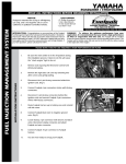
FUEL MANAGEMENT
GET THE MOST OUT OF YOUR RIDING EXPERIENCE...
AN AFTERMARKET EXHAUST SYSTEM IS ONLY YOUR FIRST STEP, NOW YOU NEED FUEL MANAGEMENT.
MOR POWER : LESS NOISE
NOW YOU NEED FUELPAK.
Your fuel injected Harley-Davidson® is equipped with an ECU (electronic
control unit) that’s programmed to deliver fuel to the motor based on an air/
fuel ratio for a stock air filter and stock exhaust system. When you install a
performance exhaust system, your airflow changes, so you need a
fuel management system that adjusts your air/fuel ratio to match
the changes. That fuel management system is Fuelpak. Fuelpak
adds and takes away fuel, allowing for a more precise range of
refinement in your air/fuel ratio. Get the perfect fuel management
combination with your Vance & Hines exhaust system, get Fuelpak.
For more information visit the tuning center at fuelpakfi.com
NOTICE: Fuelpak is intended for racing or off-highway use only, and is not legal
for sale or use in California on pollution-controlled vehicles.
13861 ROSECRANS AVENUE / SANTA FE SPRINGS, CA 90670
SALES: (562) 921-7461 / TECHNICAL: (562) 926-5291 / FAX: (562) 802-0110
VANCEANDHINES.COM
Page 4 of 4
D602IN Rev. 1.1