1
ELECTROSURGICAL UNIT
1
Contents
•
•
•
•
•
•
•
•
Introduction
Principle of ESU
Application
Types of ESU
Techniques of ESU
Operation
Safety
Maintenance & Performance
checkup
• Troubleshooting
2
Introduction & History
• Cautry
• Surgical Unit
3
Electricity
• Electricity is the fundamental phenomenon in nature seen
in the attractions and repulsions of oppositely charged
objects and utilized as a source of energy ion the form of a
current
• Properties of electricity
– Electricity, which moves at nearly the speed of light, will
(1) always follow the path of least resistance
(2) Always seeks the closed path
4
Current
• Current is the movement of an electrical charge (electrons or
ions) through a circuit.
• It is measured in Ampere.
• There are two types of current
– Alternating current (AC)
– Direct Current (DC)
5
Impedance / Resistance
• It is the opposition to the flow of current
• It is measured in Ohms Ώ
• During Electrosurgery, the patient acts as impedance.
6
Voltage
• Voltage is the force that causes a current to flow in an
electrical circuit.
• It is measured in volts
7
Power
• Power is the rate at which energy is supplied.
• The energy is measured in watts (W).
• Power = Voltage x Current
P=VI
8
History
• 1875 – Electric current was passed through wire loop until they
were red hot and heat was transferred to tissue by contact
with the red hot wire
• The ESU developed by Cushing and Bovie was a spark-gap unit
that consisted of two small metal conducting pieces separated
by an air gap. It worked like the familiar automobile spark plug.
When voltage rises enough to jump across the air gap, the air
becomes ionized and functions as a conductor.
9
History
• 1924 – Ground reference generator by Dr. Harvey Cushing
and Bovie
• 1970 – solid state generator
• 1980 – Argon Electrosurgery
10
History
• Founder - Dr. Harvey Cushion and
William Bovie.
11
Principle
• Active Electrode – High Current
Concentration
• Dispersive Electrode – Low
Current and Heat dissipates
• Current concentration or density
depends on the size of the area
through which the current flows.
12
Definition of “Electrosurgery”
• Electrosurgery is a simple, well proven, method of
making surgical incisions, control bleeding and
destroying unwanted tissue cells by the use of a high
frequency "electrosurgical current".
13
Confusion……??
• Electro Cautery Unit
• Electro Surgical Unit
14
Electrocautery
• A high amount of current is passed
through the electrode and burning or
coagulation is achieved
• Electrode for Cautery – Scalpel, Wire
• Only particular organ or tissue is
targeted
• It is a Direct Current (DC) Source
15
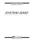
Electro Surgical Unit
• A high frequency Current
flows through active
electrode ( AC source)
• Cell ruptured- fumes or
evaporates
• Return path through
Dispersive Electrode
• Patient is included in
circuit
16
17
Effect of RF current on Cell
• When a high frequency current is
applied to the tissues, the tissue
gets torn apart and gets the
following effects
• Thermal Effect
• Electrolytic Effect and
• Faradic Effect
18
Application
• Electrocautery is used in surgery to burn unwanted or
harmful tissue. Also used to stop hemorrhage.
• Widely used in Operation Room to perform surgical
operation on patient.
• Most suitable for delicate Neurosurgery, Plastic Surgery and
Ophthalmic Surgery.
19
Application
• To remove small lesions, moles, fungus, bacteria, hair
follicles.
• Ophthalmic, Neurology, ENT ( To stop Nose Bleeding),
Gynecology, Dermatology
• Laparoscopy and Trans Urethral resection of Prostate (TURP)
• Organs - Liver, Spleen, Thyroid, Lungs and Heart Surgery
20
Operating Frequency
• The frequency of operation of solid state surgical
diathermy machine is 300KHz
KHz – 3MHz
• {Ex- Load of 500Ώ, output 400W i.e about 2000 Volt in
cutting mode and 150 W in Coagulation mode.}
21
Types of ESU
Spark Gap Generator
• Transistor circuits
• Vacuum Tubes
• Less safety for handling
•
•
•
•
Solid State Generator
Transistor Based Amplifier
Oscillator Circuit
Modified waveform- Blend
Waveform
High safety
22
Spark Gap generator
Ag/ Ag Enhanced Technology Solid
State Generator
Types of ESU
Tissue Response Technology
Grounded ESU
Isolated System
23
Grounded ESU
• Older generation
No Return Electrode causes
patient skin burn
• Electrode placement
ECG Electrodes have least
resistance to ground so site
burn at electrode placement
24
Grounded ESU
• Current seeks shortest return path to ground so by bed
side monitor, operating table or any conductive path
• Alternate site burns related to current taking pathway of
least resistance to ground
– Patient return electrode site burns
– Insulation failure injuries
– Capacitive coupling injuries
25
Isolated System
• Return Electrode introduced in solid state generator
• Advantage – No possibility of patient skin burn
• Detects for return electrode attachment
• Measures patients impedance
26
Recent Technology
Tissue Response Technology
• It uses a computer-controlled
controlled tissue feedback system that
senses tissue impedance (resistance) and automatically
adjusts the current and output voltage to maintain a
consistent surgical effect.
• Advantage - Reduces the need to adjust power settings for
different types of tissue.
• It also gives improved performance at lower power settings
and voltages, which helps to reduce the risk of patient injury.
27
Argon/Argon Enhanced Technology
• Argon Gas in Electrosurgery
• Argon Gas Properties
Inert Gas
Non combustible
Easily ionizes
Displays the blood to visualize
surgical site
– Less smoke
– It produces a beam like manner and
creates bridge between electrode
and tissue.
–
–
–
–
28
Modes of Electrosurgery
– Monopolar Surgery
– Bipolar Surgery
29
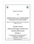
Monopolar Surgery
• RF current flows through ESU
and Active Electrode
• Returns to ESU through Return
Electrode.
• Used for cut and coagulation.
30
Bipolar Electrosurgery
• Output current flows via BIPOLAR electrode in one
terminal
• Returns the current through another terminal
• It is much safer than Monopolar surgery
• Used for cut and coagulation too.
31
Advantages of Bipolar
• It is much safer than Monopolar
• RF current flows only through well defined area, while in
Monopolar current flows back through large section of
patient body
• Risk of patient touch is low
• Less Interference for other instruments
• No ‘patient plate’ or ‘Return electrode’ is required
32
Electrode
• There are two types of Electrodes used in Electrosurgery
1. Active Electrode
2. Dispersive Electrode.
33
Active electrode
• There are two types of Active Electrode
– Cutting Electrode
– Coagulation Electrode
34
Cutting Electrode
• Cutting Electrode – They are available in
different shapes (Angulated, Needle or wire
loop shape)
Wire Loop Electrode
Angulated Electrode
35
Coagulation Electrode
• These are available in the blunt shape, ball
shape or Bipolar type. The density area of
this electrode is bit larger than cutting
electrode.
Bipolar Electrode
Ball Type Electrode
36
Dispersive / Passive Electrode
• It is also called as ‘Indifferent
Indifferent Electrode’
Electrode or ‘Patient
Return Electrode’
• Patient return electrodes remove electrical current
from the patient by completing the patient /
generator circuit.
37
Dispersive / Passive Electrode
• Lead (Metal) plate wrapped in wet cloth bag.
• Disposable Type Electrode.
• Area should be larger than active electrode about more
than 100cm²
Single Contact Surface
Double Contact Surface.
38
Placement and area of affect
• The patient becomes the part of
electronic circuit
• As the current seeks for shortest
and less resistive path to ground,
ground
user should be aware that
position of patient return
electrode should be as shorter as
possible.
39
Placement and area of affect
• If a return electrode is placed far from
the operating task, the current has to
travel a long distance, resulting increase
in the power setting.
• Accidentally, if any part of the patient
body touches to ground, a burn effect
will occur at that site.
• Ideally the arms or muscular abdomen
can be a suitable site for placement of
patient return electrode.
40
Modes of Electrosurgery
• Electrotomy / Cutting
• Desiccation
• Fulguration
41
Electrotomy / Cutting
• Tissue gets heated and tissue cell
explodes in to a steam.
• When the new tissue comes
under contact, it tears apart and
incision takes place.
42
Electrotomy / Cutting
• The RF current applied to the
tip of Electrode
• The cutting waveform has
100% Duty Cycle
43
Desiccation (Coagulation)
• In this mode ,needle or ball electrode is
kept steady inside the tissue.
tissue
• When RF current flows through the
tissue cell, it becomes hot and water
evaporates slowly so cell plasma gets
coagulated.
44
Desiccation (Coagulation)
• Coagulation By Needle Electrode or
Ball Electrode can be achieved
• Factor consideration - Intensity and
duration of Current
45
Fulguration
• There is no contact between
Active Electrode and target
tissue But electrode is close
tissue.
enough to generate the spark.
• It is a process of Coagulation.
Dehydration of cell takes place
with sparks.
• Only 6% of duty cycle is used
to produce the heat.
46
Blend Waveform
• It is a combining characteristics of cutting and
coagulation waveform that results in cutting with
moderate hemostasis.
hemostasis
•
50% ON & OFF
40% ON & 60%
% OFF
25% ON & 75% OFF
47
Impact of Tissue
In addition to waveform and power setting, other
variables impact tissue effect.
effect They include:
• Size of the electrode: The smaller the electrode, the
higher the current concentration.
concentration Consequently, the
same tissue effect can be achieved with a smaller
electrode, even though the power setting is reduced.
• Time: At any given setting, if, ESU is activated for longer
time, more heat is produced.
produced This heat can be dispersed
to the adjacent tissue.
48
Power Settings
• The power settings for various procedures varies from one
user to another, as different surgical techniques are used
with different electrodes
• Monopolar
– Low Power
•
•
•
•
•
•
•
Oral surgery
Dermatology
Polypectomy
Plastic surgery
Neurosurgery
Vasectomies
Hand surgery
49
Power Settings
• Medium Power
– Orthopedic surgery
– Normal thoracic
• General surgery
– Head/neck/ENT surgery
– Vascular surgery
– Transurethral resections (using fine loops)
• High Power
– Transurethral resections (using ball ends and thicker
loops)
– Thoracotomies for heavy coagulation
50
Power Settings
• Bipolar
– MICRO-BIPOLAR (up to 15 watts output)
• Low Power
– Eye surgery
– Fine neurosurgery
• Medium Power
– Neurosurgery
– Fine plastic surgery
• High Power
– Hand surgery
– Plastic surgery
51
Power Settings
• MACRO-BIPOLAR (up to 50 watts output)
• Low Power
– Hand surgery
– Plastic surgery
• Medium Power
– General surgery
• High Power
– Orthopedic surgery
52
Operation
53
Front Panel
• On/Off Switch – To switch ON
and Off the ESU.
• Coag Dial – Clock wise rotation of
dial to increase the output
gradually
54
Front Panel
• CUT Dial – To increase the current
density to cut a tissue.
• Pure / Blend Selector – Switch or key to
select the type of cutting current,
either PURE for minimum hemostasis
or BLEND for average hemostasis while
cutting.
55
Indicator
• COAG Mode – Indicator illuminates blue when
activating the output.
output
• CUT Mode – Indicator illuminates yellow when
CUTTING (Pure or Blend) is selected.
• Patient Return Electrode fault Indicator- for poor
patient contact alarm
56
Front Panel
• Monopolar Receptacle – It will accept three
pin hand switch forcep. Only hand switch
mechanism will work.
• Monopolar
Receptacle
–
Standard
receptacle for accessories. It will activate
only if footswitch is connected.
57
Front Panel
• Patient Return Electrode Receptacle – The
two pin connector to attach patient return
electrode in Monopolar procedure
• Bipolar Receptacle – It accepts three pin
receptacle for bipolar electrode. This will
activate with and without footswitch.
58
Rear Panel
• Foot Switch Receptacle – It
monopolar footswitch connector.
accepts
• Audio volume Control – The tone volume can
be adjusted for Cut, Coag and Bipolar mode.
• Equipotential Lug – It may be connected to
earth ground with a cable.
59
Operation
Visual Inspection
• Check continuity and condition of power cable, plugs and
Accessories cable.
• Check for any crack, insulation break , frayed cable
• Generator tone should be at an audible level
• Check instrument for proper functioning before operation.
60
Functional Test
•
•
•
•
•
•
•
•
Attach footswitch to rear panel or to the ESU receptacle end.
Attach Power Cord to AC plug.
Put ‘ON’ the main switch of ESU.
Wait for self test to pass.
Connect Monopolar / Bipolar Electrode and cable to respective
connector.
Switch ‘ON’ the High Frequency by means of pressing footswitch or
handle switch.
Increase the ‘Energy Level’ and look for audible sound and visual
light indicator.
Confirm all the time lowest power setting and confirm with surgeon.
61
Keep in mind……..
• Always prefer lowest power setting and confirm with
surgeon.
• Do attend for checking audible and visual signal.
• Patient Return Electrode is not required for Bipolar mode.
• Sparking at active electrode is a common occurrence.
• There is no guarantee for where the current flows or where
other tissue being affected.
62
Spark Gap Generator
63
Solid State Oscillator
64
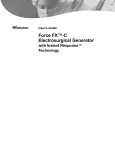
General Block Diagram
65
Power Supply
The power supply generates the supply of +5VDC,
-5VDC, +15VDC, -15VDC,
VDC, +24VDC, which is
supplied to all units. It is basically like a low voltage
power supply. The 5VDC
VDC are used for the front
panel control and Display.
Display It also monitors the
generated voltage for diagnostic purpose to
measure the current drawn from power supply.
66
Power Supply
• RF output Board – It has a power amplifier
assembly, which comprises with Bipolar,
Monopolar, CUT/ COAG and BLEND waveform.
• The output circuit is fully isolated. It generates the
out put as per front panel instruction given to
Main Board and Logic Control Board.
67
Power Supply
• It generates the Switch mode pulse pattern
generator, Drive circuit for output switching power
MOSFETS and High Frequency filtering components.
• In enhanced type generator, the output power is
managed and controlled according to patient’s
tissue impedance
68
• Memory Board – The function of this board is to
accept operating mode control signal from front panel,
rear panel and foot switch.
switch
• It checks and identifies that which connector is in use
and monitors its continuity.
continuity
• Interfaced Front Panel switch signals decode and
passes information to Display.
Display
69
Memory Board
• It has a microprocessor, used together with EPROM as
program memory and RAM.
RAM
• The analog to digital conversion of signal to convert
the commands received from front panel and fed to
logic board.
• It also generates the audible command whenever any
fault occurs during self-test
test and operation. It detects
all front panel operation and acts as per instruction
70
• Logic Board / Relay Board – The board is mainly
interfaced with Main Board or sometimes all
functions of Main Board are incorporated.
• It is a liaison between front panel and output
required. All signals are inter-related
inter
to this board.
• It gives the power output command to RF or Power
output board and monitors the output. It has relay
board too, which activates according to finger switch
or foot switch control.
71
• Front Panel – It consists of membrane keyboard,
Power switch, Patient Return Electrode, Monopolar,
Bipolar connector.
• Front panel also interfaces with Display Board and
Power Supply Board. The Power Supply Switch
supplies the AC mains current to the Electrosurgical
Unit.
72
• Display Board – It is located in the Front Panel Assembly. It
contains RF indicator lamp, Seven segment LED, Monopolar /
Bipolar mode of surgery.
• The RF indicator lamps are used for visual indication of
presence of RF power during activation. The improper
attachment of Patient Return Electrode is visually indicated by
Patient Return LED.
•
It also contains LED driver circuit and Seven Segment Display,
which indicates the Bipolar, Monopolar, Cut, Coagulation
power settings.
73
• Audio Tone Generator – It receives the command
from Main board, which activates the Audio
oscillator circuit.
• Audio circuitry gets ON at time of activation of high
frequency, any malfunction or Fault of ESU,
improper or loose attachment of patient Return
Electrode and Power up.
• It activates with signals provided by micro-controller
and gives high and low tone.
tone
74
Isolation Board
• The patient interface board is interfaced with the Main Board. It
has several different functions, which is concerned with patient
connected parts and provides the patient isolation voltage.
•
It monitors the patient plate continuity, plate voltage, BIPOLAR
forceps switch, CUT / BLEND, and COAG finger switches and
patient earth monitor.
•
It monitors the high frequency leakage current. This board
passes the Active electrode signals to main board and
continuously monitors the patient plate continuity. If any break
occurs in plate lead or not plugged IN, the related signal
activates and passes to main board to generate audible signal.
75
Safety
General Safety
• High Frequency (Sometimes referred to as radio frequency or
HF) surgery can result in serious injuries to patient if carelessly
or incorrectly applied. HF surgical instrument should be used
on patient exclusively by personnel familiar with feature and
operation of the equipment.
• In order to prevent accidental injuries due to fault, failure to
equipment or its accessories, the equipment and its accessories
should be regularly checked for proper and safe operation.
• Electrodes and cables are to fasten carefully.
76
Safety
Hazardous electrical out put
• Electrosurgical unit is recommended to use only by qualified
medical personnel. To avoid burns, do not touch active
electrodes.
• Do not operate in explosive atmosphere
• To avoid explosion, do not operate unit in an explosive
atmosphere.
• Prevent Electrosurgery use in the presence of flammable
gases, flammable liquids, or flammable objects
77
Electrical Safety
•
•
•
•
•
•
Electrosurgical units may cause interference with improperly shielded
medical equipment.
Use proper power cord.
Use only a power cord in a good condition with properly grounded
receptacle.
Use the proper fuses
To avoid fire hazard, use only fuses of correct type, voltage rating and
current rating as specified. Remove the power cord during replacement of
fuse.
Do not touch the active electrode to grounded metal parts or to the
patient plate for function proving.
The cables to HF-electrodes should be as short as possible and must be
arranged without loops so that they touch neither the patient nor other
cables. Only cables recommended by the manufacturer should be used.
Foot switches used in explosion hazard areas must be explosion proof.
78
Patient Safety
• Ensure that there is no air gap between patient’s body and patient
return electrode.
• Ensure that no small-surface area contact is made between the
patient and any of the metal parts of the treatment chair, table,
saline water stand, which conduct ground potential. Heat may be
generated at such points leading to undesired burns.
• The patient plate shall be reliable in good contact with the patient‘s
skin for the whole operation;
• If patient plate is fastened at limbs, Be careful that it doesn’t affect
the supply of blood.
79
Patient Safety
• The return path of the HF-current
current shall be as short as possible
and in longitudinal or diagonal direction of the body. It should
not go transversely through the body, especially at the thorax.
• The patient with pacemaker should be treated and consulted
through cardiology department as the high frequency may
affect or damage to the pacemaker. Outpatient with
pacemakers should not be treated using a HF generator.
• Avoids skin to skin contact, such as fingers touching the
patient's leg, when ESU is activated.
activated
80
Patient return Electrode safety
precautions
• Discard the disposable packages that have expired.
• Use ‘Patient Return Electrode’ according to the manufacturer’s
documented instruction.
• Inspect patient return electrode before each use for wire
breakage or fraying.
• Select appropriate size patient return electrode for patient (i.e,
neonate/infant, pediatric, adult).
adult)
• Do not cut patient return electrode to accommodate patient
size.
• Shave, clean and dry at application site as needed.
81
Patient return Electrode safety precautions
• Place patient return electrode on positioned patient on a
clean, dry skin, convex area in close proximity to operative
site.
• Avoid bony scar tissue, skin over an implanted metal
prosthesis, hairy surfaces, pressure points, tissue, and areas
where fluid may pool.
• Apply finger pressure to adhesive border of the electrode
and massages entire pad area to ensure adequate contact
with the patient's skin.
82
Patient return Electrode safety precautions
• Follows manufacturers' guidelines for alarm system, check
prior to use.
• Check patient return electrode connections to confirm that
they are clean, intact, and can make effective contact.
• Remove patient return electrode gently to protect skin.
83
Active Electrode safety precautions
• Avoid coiling, bundling, or clamping of active and patient
return electrodes.
• Avoid wrapping the active electrode cord around a metal
instrument.
• Remove all metal patient jewelry to prevent current diversion
and to avoid contact with other metals.
• Place active electrodes in a non-conductive
non
holster designed to
hold electrosurgical pencils and similar accessories, when they
are not in use.
84
Active Electrode safety precautions
• Activate electrode mode and function.
• Keep active electrode free from debris
• Record placement of patient return electrode,
identification number of unit, and settings used.
• Inspect insulation on reusable and disposable
electrodes before and after use
85
Preventative Maintenance
•
Chassis / Housing - Check Exterior of unit for cleanliness and general physical condition. Be sure that plastic
housings are intact, that all hardware is present and fitting are firm and tight, and that there are no signs of
spilled liquids.
•
Mount / Fasteners - If the device is mounted on a stand or cart, examine the condition of the mount. If it is
attached to a wall or rests on a shelf, check the security of this attachment.
•
AC Plug / Receptacles – Check AC power plug for damage. Attempt to wiggle the blades to check that they
are secure. Shake the plug for loose screws. If any damage is suspected, open the plug and inspect it. Check
the fuse and fitting position.
•
Line Cord - Inspect the cord for damage & excessive bending. If damaged, replace the entire cord. Verify
the minimum power cord length before cutting the defective position.
•
Strain Relief - Examine the strain relief at both ends of the line cord. Be sure that they hold the cord
securely.
•
Circuit Breaker / Fuse - If the device has an external circuit breaker, check that it operates freely. If the
device is protected by an external fuse, check its value and type against that marked on the chassis and
ensure that a spare is provided.
86
Preventative Maintenance
•
Connectors – Examine all cables of the ESU for proper fittings and firm contact of connectors.
•
Probes - Confirm that probes for their physical condition. For disposable probes check expiry date.
•
Controls / Switches - Examine all controls and switches for physical condition, secure mounting,
and correct motion. Look for loose connections. Check for proper alignment, as well as positive
stopping. Confirm the functioning of each switch and controls proper functioning.
•
Indicators / Displays - Confirm the operation of all indicators on the unit that all segments of a
digital display function and functioning of Alarms.
•
Audible Signal - Operate the device to activate any audible signals.
•
Labeling - Check for necessary labels, and instruction cards are present.
•
Dispersive Electrode cable continuity – Check the patient return electrode continuity and any alarm
functioning on removal.
•
Accessories (Footswitch) – To check the physical integrity, connection and proper operation of all
accessories related to ESU
87
Safety Test Procedure
•
•
•
•
•
•
Switch on the safety analyzer and connect the Test lead between ENCL and
EARTH
Press set up in the main menu.
Press ‘CAL’ in the system set up.
Press “Calibrate Test Lead Enclosure/Ground.
The test results are displayed once the Calibration is complete.
Connect the Main Plug of the Electrosurgical Unit (ESU) to the Safety Analyzer
Terminal on the front panel.
88
Safety Test Procedure
•
•
•
•
•
•
Connect the calibrated Test lead between ENCL on the Safety
Analyser Terminal to the Chassis or the ground terminal of the
Electrosurgical Unit (ESU).
Ensure that the main switch on the Electrosurgical Unit (ESU) is
switched ‘ON’.
In the main menu, press Equipment Code and enter the Asset
number of the ESU.
Press Equipment Classification and select classification.
Press Start in the main menu to start the test.
Once the Electrical Safety Test is over, print the test result.
89
Quantitative Test
•
Connect the Electrosurgical Unit to the Electrosurgical Analyzer and
verify output power generated by ESU. Procedure to check Output
–
–
–
–
–
–
Power up the Electrosurgical Analyzer and wait for self test to pass.
Attach the Monopolar Electrode and patient return electrode to the
ESU.
Connect and hold Active electrode with crocodile pin to the
Electrosurgical analyzer jack, similarly connect the patient return
electrode.
Put ‘ON’ the ESU analyzer and wait for self test to pass.
Once the Main display appears select the particular load (e.g. 500 )
Put ‘ON’ the ESU and wait to complete the self-test.
90
Quantitative Test
– Select CUT mode and minimum power out put energy on
Monopolar by pressing UP and DOWN arrow key.
– Press the Hand switch or foot switch to get the output.
– Note the audible sound and measured power output. Selected
Output on ESU and Displayed output on ESU analyzer should
be same or with in range of tolerance.
tolerance
– Select the different power and note down the readings. (If it
differs refer service manual for calibration)
– Similarly check for COAG mode.
mode
– Check for Bipolar mode.
91
Troubleshooting
• Servicing Techniques
• Service Manual
• Guess or Judge
• Step by step procedure to troubleshoot.
92
Troubleshooting
USER CHECKLIST
• Check the Electrosurgical Unit (ESU) for physical damage.
• Verify all accessories cords are connected properly.
• Check the condition of power cord, it should not be frayed,
damaged, crack or exposed of any wire otherwise replace the
same immediately.
• Check the fuse of ESU. It should be firmly fitted inside the fuse
socket. Also check for any corrosion and damages if so replace
the same rating of fuse as mentioned in manual and on ESU.
93
Troubleshooting
• Disconnect the power cord and check for Footswitch receptacle
damage or obstruction. If found replace the rear panel or rear
panel connector.
• Check for the firm contact of Bipolar Instrument receptacle on
front panel for obstruction and damage. If found replace the
front panel or front panel connector.
connector
• Check for the firm contact of Monopolar instrument receptacle
on front panel for any obstruction and damage. If found
replace the front panel or front panel connector.
• Check the patient return electrode receptacle for any broken
pins and obstruction. If found replace the front panel or front
panel connector
94