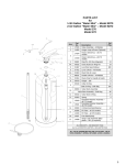
1
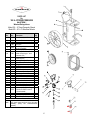
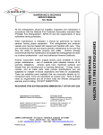
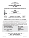
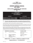
OWNERS SERVICE MANUAL
NO. 16672
INSTALLATION, OPERATING & SERVICING INSTRUCTIONS
for
AMEREX
WHEELED STORED PRESSURE
HALOTRON l “CLEAN AGENT” FIRE EXTINGUISHERS
MODEL 673 - 65 POUND
MODEL 674 & 675 - 150 POUND
* * * HAVE EXTINGUISHERS RECHARGED IMMEDIATELY AFTER ANY USE * * *
All fire extinguishers should be installed, inspected and maintained in accordance with the National Fire
Protection Association standard titled "Portable Fire Extinguishers", NFPA-10 and the requirements of local
authorities having jurisdiction.
When maintenance is indicated it should be performed by trained persons having proper equipment. Fire
extinguishers are pressure vessels and must be treated with respect and handled with care. They are
mechanical devices and require periodic maintenance to be sure that they are ready to operate properly and
safely. Amerex strongly recommends that the maintenance of portable fire extinguishers be done by a trained
professional – your local authorized Amerex Distributor.
Amerex Corporation makes original factory parts available to insure proper maintenance – use of substitute
parts releases Amerex of its warranty obligations. Amerex parts have machined surfaces and threads that are
manufactured to exacting tolerances. O-rings, hoses, nozzles, and all metal parts meet precise specifications
and are subjected to multiple in-house inspections and tests for acceptability. There are substitute parts
available that are incorrectly labeled as UL component parts, some are advertised as Amerex type. None of
these meet UL requirements and all of them voids the Amerex extinguisher warranty and UL listing. DO NOT
SUBSTITUTE.
REFERENCES IN THIS MANUAL:
NFPA-10 Portable Fire Extinguishers
AVAILABLE FROM:
National Fire Protection Association
1 Batterymarch Park, P. O, Box 9101
Quincy, MA 02269-9101
CGA C-1 Methods for Hydrostatic Testing of
Compressed Gas Cylinders
CGA C-6 Standard for Visual Inspection of
Compressed Gas Cylinders
Compressed Gas Association, Inc.
4221 Walney Road, 5th Floor
Chantilly, VA 20151-2923
AMEREX CORPORATION – P.O. BOX 81 – TRUSSVILLE, ALABAMA 35173-0081
Phone: (205) 655-3271
Fax: (800) 654-5980
Web Page: http://www.amerex-fire.com
e-mail: [email protected]
Printed in U.S.A.
OM16672Rev.12/03
INTRODUCTION
This manual covers specific instructions for the Amerex wheeled Models 673 (65 lb., 16” semi-pneumatic
wheels), 674 (150 lb., 16” semi-pneumatic wheels), and 675 (150 lb., 36” wide steel wheels)
extinguishers. Special maintenance and recharge instructions contained in this manual apply to these
extinguishers only. Halotron l “Clean Agent” extinguishers are designed for Class A, B, and C hazards
formerly protected with Halon 1211 extinguishers. They contain dichlorotrifluoroethane (R-123), which is
designated for streaming fire extinguisher applications. Halotron l is listed in the U.S. Environmental
Protection Agency (EPA) “Significant New Alternative Policy” (SNAP) as acceptable for nonresidential
applications. Halotron l has acceptable toxicity and cardiac sensitization levels for use in occupied spaces
when used according to the instructions on the nameplate and rules of the EPA SNAP Program.
PHYSICAL PROPERTIES OF HALOTRON l
Primary Component
Dichlorotrifluoroethane (R-123) or (HCFC-123)
Boiling Point
80.6°F [27°C]
Liquid Density
92.3 lb./ft³ (1.48 kg / liter)
Gas Density
0.385 lb./ft³ (6.17 kg / m³)
Molecular Weight
150.68
Physical State
Pressurized Liquid
Vapor Pressure @ 68ºF [20ºC] (liquid alone) 11.2 psi [77 kPa]
Pressure of mixture in Container @ 68ºF [20º] 95 psig in bulk container
HALOTRON l LIMITED WARRANTY
Amerex warrants its Halotron l fire extinguishers to be free from defects in material and workmanship
for a period on ONE (1) YEAR from the date of purchase or first recharge, whichever comes first.
During the warranty period, any such defects will be repaired or the defective extinguisher replaced at
Amerex discretion. This warranty does not cover defects resulting from modification, alteration, misuse,
exposure to corrosive conditions or improper installation. ALL IMPLIED WARRANTIES, INCLUDING,
BUT NOT LIMITED TO, WARRANTIES OF FITNESS FOR PURPOSE AND MERCHANTABILITY, ARE
LIMITED TO THE TIME PERIODS AS STATED ABOVE. IN NO EVENT SHALL AMEREX CORPORATION
BE LIABLE FOR INCIDENTAL OR CONSEQUENTIAL DAMAGES. Some states do not allow limitations on
how long an implied warranty lasts or the exclusion or limitation of incidental or consequential damages,
so that the above limitations or exclusions may not apply to you. Amerex Corporation neither assumes nor
authorizes any representative or other person to assume for it any obligation or liability other than as
expressly set forth herein. This warranty gives you specific legal rights, and you may also have other
rights, which vary from state to state. To obtain performance of the obligation of this warranty, write
to Amerex Corporation, P.O. Box 81, Trussville, AL 35173-0081 for instructions.
Amerex Corporation does not service, maintain or recharge fire extinguishers. The maintenance and
recharge portion of this manual is published as a guide to assist service personnel in the inspection,
maintenance and recharge of Amerex Halotron l wheeled fire extinguishers only. No instruction manual
can anticipate all possible malfunctions that may be encountered in the service of fire extinguishers.
Amerex assumes no liability for service, maintenance or recharge of fire extinguishers by publishing this
manual. To provide optimum extinguisher reliability, recharging should be performed by persons trained in
fire extinguisher maintenance and servicing. This manual should be used as a guide for installing and
servicing these Amerex extinguishers. The best place to have your extinguishers serviced and recharged
is your "Authorized Amerex Distributor" who has the professional experience and equipment to do it
properly.
1
THIS MANUAL IS ATTACHED TO EVERY NEW EXTINGUISHER SHIPPED FROM THE FACTORY.
IT CONTAINS VALUABLE INFORMATION WHICH SHOULD BE STUDIED BY EVERYONE WHO
WILL USE OR SERVICE THE EXTINGUISHER.
THE MANUAL SHOULD BE STORED IN A
CONVENIENT LOCATION FOR EASY REFERENCE.
PREPARING YOUR NEW EXTINGUISHER FOR USE
1. Remove all wrappings, straps and pallet retaining bolts.
2. Examine the extinguisher for shipping damage.
3. Check to insure that the hose connection at the discharge valve and the nozzle connection to the
hose are tight.
4. Check to insure that the nozzle shut-off lever is in the CLOSED position. The pull pin should be
installed and the tamper seal intact.
5. Visually inspect t he p r es s u r e g a u g e. The pressure gauge sho u l d b e i n t he green zone.
Slight pressure variances in the gauge reading may be found if the extinguisher has been
subjected to extremes of heat or cold. High temperatures can cause high gauge readings and low
temperatures, low readings. When in doubt, condition the extinguisher to 70ºF (21ºC) for
several hours to obtain more accurate pressure gauge readings.
6. The method used to determine proper agent fill is by weighing the extinguisher. The gross weight
is marked on each extinguisher nameplate.
7. Record the date the unit is being placed into service on the inspection tag and attach it to the
extinguisher.
INSTALLATION
Do not place this extinguisher close to a potential fire hazard. Amerex recommends a location no
less than a 50-foot distance from the hazard while leaving an unobstructed access. Avoid placing it
in an extremely hot or cold area. The operational temperature range for this ex t i ng u i s her is
–40°F to 120°F (-40°C to 49°C). The extinguisher should be adequately protected if temperatures
outside of this range are anticipated. Keep the extinguisher clean and free from dirt, ice, chemicals
and any contaminants that may interfere with its proper operation. DO NOT FUNCTIONALLY TEST
THIS FIRE EXTINGUISHER. (Testing or any use may cause the extinguisher to gradually lose
extinguishing agent over a period of time and make the extinguisher ineffective.)
OPERATION
WARNING:
PERSONS EXPECTED TO USE THIS EXTINGUISHER SHOULD BE MADE AWARE
OF THE CONFINED SPACE LIMITATIONS AND TRAINED IN INITIATING ITS
OPERATION AND PROPER FIRE FIGHTING TECHNIQUE. THE CONCENTRATED
AGENT CAN PRODUCE TOXIC BY-PRODUCTS. AVOID INHALATION OF THESE
MATERIALS BY EVACUATING THE CONFINED SPACE.
DO NOT USE IN
CONFINED SPACES SMALLER THAN THE MINIMUM STATED ON THE
EXTINGUISHER LABEL.
CAUTION:
Persons expected to use this extinguisher should be trained in initiating its
operation and in the proper fire fighting technique. "Dry Run" and visual aid
training will prepare personnel with the feel for this extinguisher so that the most
effective application can be utilized in an emergency situation. The basic operating
instructions are contained on the pictogram of every extinguisher. The following
elaborates on these instructions:
1. Move the extinguisher to within approximately 50 feet of the fire site. KEEP UPRIGHT.
2
2. Twist and pull ring pin and open cylinder valve by rotating (pulling) the valve lever toward the hose
90°. The hose is now pressurized.
3. Pull nozzle with nozzle lever in the closed position from the nozzle mount and extend hose from
the storage rack.
4. Stand back 30 feet from the fire and aim just in front of the base of the flames nearest you.
5. Hold hose and nozzle firmly and be prepared for a discharge recoil. Open nozzle by pulling lever
toward you. Slowly sweep side to side extending the discharge beyond the edges of the fire.
Progressively follow up until the fire is extinguished. Work the fire away from you while being
alert for flashbacks. Move closer as the fire is extinguished but not so close as to scatter or
splash the burning material. Shut off nozzle lever to stop discharge. Stand and watch for
possible re-ignition.
6. Evacuate and ventilate the area immediately after extinguishing the fire. The fumes and smoke
from any fire may be hazardous and can be deadly.
WARNING: SYMPTOMS OF OVER-EXPOSURE TO PURE HALOTRON l MAY CAUSE CENTRAL
NERVOUS SYSTEM EFFECTS SUCH AS DIZZINESS, DROWSINESS, ANESTHESIA, OR
UNCONSCIOUSNESS.
PERSONS SUFFERING FROM OVER-EXPOSURE SHOULD BE
IMMEDIATELY REMOVED TO AREA WITH FRESH AIR. APPLY ARTIFICAL RESPIRATION IF
NECESSARY. CONTACT A PHYSICIAN.
Discharge Time (approx.)
Range (Agent Thow)
Hose Length
MODEL 673
22 seconds
30 to 45 feet
50 feet
MODEL 674
38 seconds
30 to 45 feet
50 feet
MODEL 675
38 seconds
30 to 45 feet
50 feet
BEFORE PREPARING TO MOVE THE EXTINGUISHER TO THE RECHARGE LOCATION,
DETERMINATION MUST BE MADE THAT THE FIRE IS COMPLETELY EXTINGUISHED AND THERE
IS NO DANGER OF A FLASHBACK.
SHUTDOWN
1. Close the discharge hose valve. Rotate cylinder discharge valve lever 90° to the CLOSED position.
2. Locate the extinguisher in an open area where blow down can be accomplished safely.
3. Tip the extinguisher to rest the carriage handle/tow loop on the ground. Slowly open the discharge
hose valve and cylinder valve. Be prepared for some chemical discharge. Relieve all pressure in the
cylinder and clear the discharge hose of all Halotron l. To prevent any loss of remaining agent, the
carriage handle/tow loop should be positioned as low as possible in a plane below the bottom on the
cylinder.
CAUTION: DO NOT LEAVE HALOTRON l IN THE HOSE AS OVER-PRESSURIZATION
AND DETERIORATION OF THE HOSE MAY OCCUR.
4. When the hose is empty, push the discharge hose valve nozzle lever and cylinder valve lever to the
CLOSED positions.
5. Return the extinguisher to an upright position. Coil the extinguisher hose onto the storage rack and
position the nozzle onto the mount in preparation for transport to the recharge location.
RECHARGE FIRE EXTINGUISHERS IMMEDIATELY AFTER ANY USE
3
INSPECTING THE EXTINGUISHER
INSPECTION [NFPA-10 3.3.10 (2002)] is a "quick check" that a fire extinguisher is available and is in
operating condition. It is intended to give reasonable assurance that the fire extinguisher is fully charged.
This is done by verifying that it is in its designated place, that it has not been actuated or tampered with,
and that there is no obvious physical damage or condition to prevent its operation.
PERIODIC INSPECTION PROCEDURES
(monthly or more often if circumstances dictate)
[NFPA-10 6.2.2 (2002)] Periodic inspection of fire extinguishers shall include a check of at least the following items:
1.
2.
3.
4.
5.
6.
7.
8.
9.
10.
Location in designated place
No obstruction to access or visibility
Operating instructions on nameplate legible and facing outward
Seals and tamper indicators not broken or missing
Determine fullness by weighing
Examination for obvious physical damage, corrosion, leakage, or clogged nozzle
Pressure gauge reading in the operable range
Hose properly coiled and shut-off nozzle in its mount in closed position
Condition of tires/wheels and that they rotate freely
HMIS label in place
MAINTENANCE
(At least once a year or when specifically indicated by an inspection.)
Maintenance [NFPA 10 3.3.18 (2002)] is a thorough examination of the fire extinguisher. It is intended
to give maximum assurance that a fire extinguisher will operate effectively and safely. It includes a
thorough examination for physical damage or condition to prevent its operation and any necessary repair or
replacement. It will normally reveal if hydrostatic testing or internal maintenance is required.
MAINTENANCE PROCEDURE
1.
Clean extinguisher to remove dirt, grease or foreign material. Check to make sure that the instruction nameplate
and UL manifest are securely fastened and legible. Inspect the cylinder for corrosion, abrasion, and dents or weld
damage. If any of these conditions are found and you doubt the integrity of the cylinder, hydrostatically test to
factory test pressure, using the proof pressure method in accordance with CGA C-6 and NFPA 10.
NOTE: When cleaning avoid use of solvents around the pressure gauge. They could seriously damage the plastic
gauge face.
2.
Inspect the extinguisher for damaged, missing or substitute parts. Only factory replacement parts are approved
for use on Amerex fire extinguishers.
3.
Weigh extinguisher and compare with weight printed in the Maintenance section on the nameplate. Recharge
extinguisher if weight is not within indicated allowable tolerances.
4.
Check the date of manufacture stamped into the cylinder. Cylinder must be hydrostatically (proof pressure)
tested every 12 years to the test pressure indicated on the nameplate. Model 673, 65 lb. = 480 psi (3309 kPa);
Models 674 and 675, 150 lb. = 1000 psi (6895 kPa).
4
5.
Visually inspect the pressure gauge:
a. if bent, damaged or improper gauge, depressurize and replace
b. if pressure is low or high and temperature/pressure relationship has been ruled out:
1. low pressure – check for leaks
2. high pressure (over pressurized or over charged) depressurize and recharge extinguisher following
instructions listed below
6.
Remove and check ring pin for freedom of movement. Replace if bent or if removal appears difficult.
7.
Check the nozzle shutoff lever for freedom of movement (open and close several times). If the operation is
impeded, replace ball valve assembly. Make sure that the nozzle tip is clear and unobstructed.
WARNING:
ALWAYS OPEN THE SHUTOFF NOZZLE HANDLE SLOWLY. BE PREPARED
FOR A POSSIBLE DISCHARGE AND NOZZLE RECOIL.
8.
After making sure that there is no residual pressure in the discharge hose, disconnect it from the cylinder
operating valve. Blow air through the hose and nozzle assembly to insure that the passage is clear of foreign
material. Check the couplings, hose and hose gasket for damage or deterioration – replace as necessary.
9.
Inspect valve assembly for corrosion or damage to hose thread connection. Valve removal and/or valve part
replacement should be made only after following the depressurizing and recovery procedures listed in the Complete
Maintenance procedures.
10. Inspect the wheels to insure they rotate freely. Lubricate as required.
11. Check carriage assembly for loose nuts, bolts, frame distortion or damage. Check welds for damage or corrosion.
Replace damaged parts or make repairs as necessary.
12. Reconnect the hose to the agent cylinder. Properly coil the hose on the rack and install the nozzle (with the lever
in a closed position) on the mount.
NOTE: When assembling the hose to the agent cylinder or nozzle to the hose, tighten the coupling ¼ turn after
contacting the hose gasket.
13. Install new tamper seal and record service data on the extinguisher inspection tag.
14. If the extinguisher has been moved to perform service, make sure that it is returned to its proper location.
COMPLETE MAINTENANCE (SIX YEAR MAINTENANCE)
Six Year Maintenance [NFPA-10 6.3.3 (2002)]. Every 6 years, stored-pressure fire extinguishers that require a 12
year hydrostatic test shall be emptied and subjected to the applicable maintenance procedures. When the applicable
maintenance procedures are performed during the periodic recharging or hydrostatic testing, the 6-year requirement
shall begin from that date.
a.
WARNING
Before attempting to devalve the extinguisher for maintenance, hydrotest or recharging be sure that it
is completely depressurized. Recover agent and vapor according to the instructions below.
b.
Never have any part of your body over the extinguisher while removing the valve assembly.
c.
Prolonged exposure of a devalved cylinder to ambient air should be avoided to prevent moisture
contamination and cylinder rusting.
5
COMPLETE MAINTENANCE (SIX YEAR MAINTENANCE) PROCEDURES
1.
Complete items 1 through 11 in Maintenance Procedure above.
2.
Attach the appropriate recharge adapter (P/N 09857) to the extinguisher operating valve on the
extinguisher cylinder. Empty the extinguisher of all pressure and Halotron l using an Amerex P/N
14538 Halotron l Recharge Kit and a bulk Halotron l supply cylinder with sufficient empty capacity to
accept the contents of the extinguisher.
3.
When extinguisher is empty of all agent and pressure, remove valve assembly and disassemble by
removing downtube, spring and valve stem assembly. Discard valve stem assembly and collar o-ring.
NOTE: Keep cylinder opening covered while devalved to minimize interior
corrosion.
4.
Thoroughly clean all parts of the disassembled valve with a soft bristle brush or soft cloth. Blow the
valve out with dry nitrogen.
5.
Install a NEW valve stem assembly (GREEN SEAL) after lightly lubricating the valve stem o-ring with
Visilox 728 (do not lubricate the valve stem seal). Reassemble the spring and downtube. Carefully
install a NEW collar o-ring (GREEN) which has been lightly lubricated with Visilox 728. Set the valve
assembly aside.
6.
Inspect the cylinder interior following CGA Visual Inspection Standard C-6. If a hydrotest has been
performed or any moisture is evident, the cylinder should be immediately warm air dried.
7.
Clean the o-ring seating groove in the cylinder neck. If any rust is evident, remove by using a fine
emery cloth (200 grit). Clean the surface and lubricate the entire sealing area with a thin film of
Visilox 728. Install the valve assembly in extinguisher cylinder. Hand tighten firmly.
8.
Complete the Recharge steps, items 2 through 11.
RECHARGE
RECHARGING [NFPA-10 3.3.21 (2002)] is the replacement of the extinguishing agent (also includes the
expellant for this type of extinguisher).
WARNING:
a.
b.
c.
Halotron l service should be performed only in a well ventilated room by a
properly trained service technician wearing proper eye protection and rubber
gloves.
Before attempting to recharge be sure this extinguisher is completely
depressurized by slowly and carefully depressing the operating lever and
discharging the extinguisher into a proper collection area.
Use a REGULATED pressurizing source of ultra high purity ARGON ONLY. Set
the regulator to no more than 25 PSI higher than the extinguisher gauge
operating pressure.
6
d.
e.
Check and calibrate regulator gauge at frequent intervals. The regulator gauge
should be used to determine when the intended charging pressure has been
reached. Do not use the extinguisher gauge for this purpose.
Never leave an extinguisher connected to a regulator of a high pressure source
for an extended period of time. A defective regulator could cause the cylinder
to rupture due to excessive pressure.
RECHARGING PROCEDURE
Note: The following procedure is for an EMPTY Halotron l extinguisher. If you are recharging an
extinguisher, which has been partially discharged (with agent remaining in the cylinder) or has
been recharged and the pressure leaked, follow the instructions contained in the Recharging
Instructions, which is packaged with the Amerex Recharge Kit (P/N 14538).
1.
Perform the Complete Maintenance steps 1 through 7.
2.
Install the proper Amerex Recharge Adapter and draw a vacuum of 27” of mercury (adjusted for
altitude variations) [see your vacuum pump manual for detailed instructions].
3.
Stand the extinguisher upright on a scale of sufficient size and capacity (200 lbs. minimum). Tare
weight extinguisher or record empty weight. The extinguisher should be fully discharged and
empty.
4.
Connect the extinguisher to a Halotron l supply cylinder using the Amerex P/N 14538 Halotron l
Recharge Kit.
Note: The Halotron l supply cylinder must be pressurized to approximately 100 psi with ARGON
to properly charge the extinguisher.
5.
Open the agent cylinder discharge valve by pulling 90º toward the hose rack and fill extinguisher to
the agent fill weight noted on the nameplate USING ONLY CLEAN UNCONTAMINATED
HALOTRON l AGENT. [see detailed instructions on your recharging system]
CAUTION: Avoid liquid Halotron l contact with the external extinguisher cylinder.
6.
Pressurize to the extinguisher operating pressure with ARGON only. Repeatedly rock the
extinguisher to thoroughly mix the ARGON pressurizing gas until proper pressure is reached. Add
additional Argon as necessary until the pressure stabilizes.
7.
Check extinguisher for leaks at the valve orifice, around the collar seal, and gauge using a Halogen
Leak Detector. The alternate method is to apply leak detecting fluid or a solution of soapy water to
these areas. Thoroughly remove all leak detection fluid residue using dry nitrogen to blow all liquid
residue out of the valve and wipe the extinguisher to dry the exterior. DO NOT LEAVE ANY
LIQUID INSIDE THE VALVE BODY. Remove the recharge adapter.
CAUTION: If you use a Halogen type leak detector: A residual amount of Halotron l will
remain in the valve body until the liquid evaporates. To properly leak test using the Halogen
leak detector it is recommended that the extinguisher be set aside a minimum of 24 hours
after recharging, then leak tested.
7
8.
Install ring pin and new tamper seal.
9.
Install hose assembly, with shut-off nozzle attached, to the extinguisher cylinder discharge valve.
Tighten hose coupling ¼ turn after contact with hose gasket. Coil hose onto the hose rack and
install nozzle into mount.
10.
Weigh extinguisher to confirm that the total weight is within the tolerances indicated in the
maintenance section on the extinguisher nameplate.
11.
Record recharge date and attach new recharge tag in accordance with the requirements of the
"Authority Having Jurisdiction".
TROUBLE SHOOTING GUIDE
WARNING: DETERMINE THE SOURCE OF A LEAK BEFORE THE EXTINGUISHER IS
DEPRESSURIZED.
THE EXTINGUISHER MUST BE COMPLETELY DEPRESSURIZED BEFORE ANY
ATTEMPT IS MADE TO REMOVE THE VALVE ASSEMBLY AND CORRECT THE LEAKAGE PROBLEM.
SEE INSTRUCTIONS PACKAGE WITH THE AMEREX HALOTRON l RECHARGE KIT P/N 14538 FOR THE
PROPER METHOD OF DEPRESSURIZING THE EXTINGUISHER TO AVOID UNNECESSARY DISCHARGE
AND MINIMUM AGENT LOSS.
1.
2.
3.
4.
5.
6.
7.
*
PROBLEM
Pressure gauge reads high or
low
CORRECTIVE ACTION
Pressure variances in the gauge reading may be found if the
extinguisher has been subjected to extremes of heat or cold. High
temperatures can cause high gauge readings and low temperatures,
low readings. When in doubt, condition the extinguisher to 70ºF
(21ºC) for several hours to obtain more accurate pressure gauge
readings.
Leak through valve
Remove valve assembly, downtube, spring and valve stem assembly.
Install new valve stem (GREEN SEAL) assembly. Check valve seat
for scratches or foreign matter.
Leak at collar o-ring
Remove valve assembly, clean collar o-ring seating surface
thoroughly and lubricate lightly with Visilox-728. Install new collar
o-ring (GREEN) after lubricating with Visilox V-728.
Leak around gauge threads
Remove gauge* and reinstall using Teflon tape on the gauge threads.
Defective gauge
Remove defective gauge* and install a new gauge using Teflon tape
on the gauge threads.
Leak in cylinder
Contact Amerex if under warranty, otherwise mark “REJECTED”
and return to owner.
Visible deterioration of
Replace hose assembly. Extinguishing agent has been stored in hose
discharge hose
for a prolonged time. See Caution in Shut-Down procedures.
Pressure gauge threads are coated with a special epoxy at the factory. For easy removal soak the
valve assembly in hot water (180° F/82°C) for two to four minutes. Remove gauge with a 7/16” open
end wrench.
8
PARTS LIST
For
65 lb. Stored Pressure
Halotron 1
Wheeled Extinguishers
Model 673 – 16” Semi-Pneumatic Wheels
Item
No.
1
2
3
4
5
6
Part
No.
16661
04938
16724
16690
06130
07481
7
07751
8
9
10
11
12
13
14
15
16
17
18
19
20
21
22
04945
06059
16723
14417
06100
01387
16666
06060
16664
16668
03556
03501
06279
03877
16659
23
05723
24
25
-
05152
09857
06247
NOTE:
9
Description
Valve Assembly with Downtube
Downtube/Retainer Assembly
Carriage Assembly w/o Wheels
Hose Support w/hardware
Nozzle Mount with Hardware
Pictogram
Wheel Assembly, 16" with Hubcap,
Washer and Retaining Pin, SemiPneumatic
Hubcap
Valve Lever w/Screws
Gauge Guard Assembly
100 PSI Gauge
Ring Pin, SS with Wire
Tamper Seal (Yellow)
Valve Body
Cam Assembly w/o-rings
Collar O-Ring
Valve Stem Assembly
Spring
Hose Assembly ¾’ X 50’
Ball Valve Assembly
Gasket, Hose/Nozzle
Nozzle Tip (.395)
Hydrotest Adapter (Male Plug). Use
with P/N 09857 to test 50 ft. hose
assembly
Hydrotest Adapter (Cylinder)
Recharge Adapter
Visilox Lub. (5 oz. tube)
Std.
Pkg.
1
1
1
1
1
1
1
1
1
1
1
12
500
1
1
24
6
6
1
1
6
1
1
1
1
1
Replacement valve assemblies incude new valve body,
gauge, gauge guard, cam lever, valve stem assembly,
spring and downtube/retainer assembly.
PARTS LIST
For
150 lb. STORED PRESSURE
HALOTRON 1
Wheeled Extinguishers
Model 674 – 16" Semi-Pneumatic Wheels
Model 675 – 36" x 6" Wide Steel Wheels
Item
No.
Part
No.
1
16677
Valve Assembly with Downtube
1
2
3
4
16726
16727
07481
1
1
1
5
16725
6
07026
6A
07551
7
07389
7A
8
9
10
11
12
13
14
15
16
17
18
19
20
21
04945
06059
16723
14418
06100
01387
06060
16666
16664
16668
16679
03877
06279
16674
03501
22
05723
23
24
-
05152
09857
06247
Downtube/Retainer Assembly
Carriage Assembly w/o Wheels
Pictogram
Hose Support Asy with
Mounting Hardware
Wheel Asy-36"x6" – Red (675)
Wheel Asy–16" w/hubcap,
washer & retaining pin – semipneumatic (674)
Hubcap (metal) w/washer &
Cotter Pin (675)
Hubcap (plastic) – (674)
Valve Lever w/Screws
Gauge Guard Assembly
125 PSI Gauge
Ring Pin, SS with Wire
Tamper Seal (Yellow)
Cam Assembly w/o-rings
Valve Body
Collar O-Ring
Valve Stem Assembly
Spring
Gasket – Hose/Nozzle
Ball Valve Assembly
Nozzle Tip (.687)
Hose Assembly ¾" x 50'
Hydrotest Adapter (Male Plug)
Use with P/N 09857 to test 50
ft. Hose Assembly
Hydrotest Adapter (Cylinder)
Recharge Adapter
Visilox Lub. (5 oz. Tube)
NOTE:
Description
Std.
Pkg.
1
1
1
1
1
1
1
1
12
500
1
1
12
6
6
6
1
1
1
1
1
1
1
Replacement valve assemblies include new valve
body, gauge, gauge guard, cam, lever, valve stem
assembly, spring and downtube/retainer
assembly
10