1
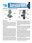
OWNERS SERVICE MANUAL
NO. 05618
INSTALLATION, OPERATING & SERVICING
INSTRUCTIONS
for
AMEREX
CARBON DIOXIDE
MODEL 333 50 POUND WHEELED
MODEL 334 100 POUND WHEELED
MODEL 335 100 POUND STATIONARY
* * * RECHARGE FIRE EXTINGUISHERS IMMEDIATELY AFTER ANY USE * * *
All fire extinguishers should be installed, inspected and maintained in accordance with the National Fire
Protection Association standard titled "Portable Fire Extinguishers", NFPA-10 and the requirements of local
authorities having jurisdiction.
When maintenance is indicated it should be performed by trained persons having proper equipment. Fire
extinguishers are pressure vessels and must be treated with respect and handled with care. They are mechanical
devices and require periodic maintenance to be sure that they are ready to operate properly and safely. Amerex
strongly recommends that the maintenance of portable fire extinguishers be done by a trained professional – your
local authorized Amerex Distributor.
Amerex Corporation makes original factory parts available to insure proper maintenance – use of substitute parts
releases Amerex of its warranty obligations. Amerex parts have machined surfaces and threads that are
manufactured to exacting tolerances. O-rings, hoses, nozzles, and all metal parts meet precise specifications and
are subjected to multiple in-house inspections and tests for acceptability. There are substitute parts available that
are incorrectly labeled as UL component parts, some are advertised as Amerex type. None of these meet UL
requirements and all of them voids the Amerex extinguisher warranty and UL listing. DO NOT SUBSTITUTE.
REFERENCES IN THIS MANUAL:
NFPA-10 Portable Fire Extinguishers
AVAILABLE FROM:
National Fire Protection Association
1 Batterymarch Park, P. O, Box 9101
Quincy, MA 02269-9101
CGA C-1 Methods for Hydrostatic Testing of
Compressed Gas Cylinders
CGA C-6 Standard for Visual Inspection of
Compressed Gas Cylinders
Compressed Gas Association, Inc.
4221 Walney Road, 5th Floor
Chantilly, VA 20151-2923
AMEREX CORPORATION – P.O. BOX 81 – TRUSSVILLE, ALABAMA 35173-0081
Phone: 205/655-3271 Fax: 800/654-5980
e-mail: [email protected]
Web Page: http://www.amerex-fire.com
Printed in U.S.A.
0M05618 Rev 9/05
LIMITED WARRANTY
Amerex warrants its fire extinguishers to be free from defects in material and workmanship for a period of six (6)
years from the date of purchase. During the warranty period, any such defects will be repaired or the defective
extinguisher replaced if the original grey lockwire seal is intact and/or if only factory replacement parts and
recommended service equipment have been used to service the extinguisher. This warranty does not cover
defects resulting from the modification, alteration, misuse, exposure to unusually corrosive conditions nor
improper installation or maintenance. All implied warranties, including but not limited to, warranties of fitness for
purpose and merchantability, are limited to the time periods as stated above. In no event shall Amerex
Corporation be liable for incidental or consequential damages. Some states do allow limitations on how long an
implied warranty lasts or the exclusion or limitation of incidental or consequential damages, so that the above
limitations or exclusions may no apply to you. Amerex Corporation neither assumes nor authorizes any
representative or other person to assume for it any obligation or liability other than as expressly set forth herein.
This warranty gives you specific legal rights, and you may also have other rights which vary from state to state.
To obtain performance of the obligation of this warranty, write to Amerex Corporation, P. O. Box 81, Trussville, AL
35173-0081 for instructions.
THIS MANUAL IS ATTACHED TO EVERY NEW EXTINGUISHER SHIPPED FROM THE FACTORY. IT
CONTAINS VALUABLE INFORMATION WHICH SHOULD BE STUDIED BY EVERYONE WHO WILL USE OR
SERVICE THE EXTINGUISHER. THE MANUAL SHOULD BE STORED IN A CONVENIENT LOCATION FOR
EASY REFERENCE.
PREPARING YOUR NEW EXTINGUISHER FOR USE
1. Remove all wrappings, straps and pallet retaining bolts.
2. Examine the extinguisher for shipping damage.
3. Remove shipping cap(s) from CO2 cylinder(s). Install discharge hose (50 lb.) or manifold (100 lb.) to
cylinder valve(s). check to insure that the hose connection to the operating valve/or manifold and hose to
the squeeze grip shut-off valve are tight.
4. Check to insure that the cylinder valve(s) are in the CLOSED position. The ring (locking) pin should be
installed and the lockwire seal intact.
5. Visually inspect t he safety relief on the cylinder valve for evidence of obstruction or damage. DO NOT
REMOVE.
6. This extinguisher is shipped from the factory fully charged. The most accurate method to determine if the
extinguisher is filled with the proper amount of Caron Dioxide is to weigh the unit. The gross weight is
indicated on the lower right hand corner of the pictogram operation INSTRUCTIONS (plus weight of
cylinders stamped on cylinder valve{s}),
7. Record the date the unit is being placed into service on the inspection tag and attach it to the
extinguisher.
INSTALLATION
Do not place this extinguisher close to a potential fire hazard. Amerex recommends location no less than a
20 foot distance from the hazard while leaving an unobstructed access. Avoid placing it in an extremely hot
or cold place. The operational temperature range for this e xt i n g ui she r is –40°F to 120°F (-40°C to 49°C).
The extinguisher should be adequately protected if temperatures outside of this range are anticipated. Keep
the extinguisher clean and free from dirt, ice, chemicals and any contaminants that may interfere with its
proper operation. DO NOT FUNCTIONALLY TEST THIS FIRE EXTINGUISHER. (Testing or any use may
cause the extinguisher to gradually lose extinguishing agent over a period of time and make the extinguisher
ineffective.)
OPERATION
WARNING:
HIGH CONCENTRATIONS OF CARBON DIOXIDE CAN CAUSE RESPIRATORY
PROBLEMS. SELF CONTAINED BREATHING APPARATUS OR AIR LINE RESPIRATORS
SHOULD BE USED IF OXYGEN LEVEL HAS BEEN DIMINISHED BELOW 19%. AVOID
SKIN CONTACT – CO2 IS VERY COLD AND COULD CAUSE BURNS OR FROSTBITE.
CAUTION:
Persons expected to use this extinguisher should be trained in initiating its operation
and in the proper fire fighting technique. "Hands on" training will prepare personnel
with the feel for this extinguisher so that the most effective application can be utilized in
an emergency situation. The basic operating instructions are contained in the
pictogram portion of every extinguisher nameplate (label). The following elaborates on
these instructions.
1
1. Move the extinguisher (wheeled unit) to within approximately 10 feet (50 lb.), 30 feet (100 lb.) of the fire
site.
2. Twist and pull ring pin(s). Pull “T” handle cylinder valve lever(s) to open cylinder valve. Pull hose from
rack. Start back 10 feet from the fire.
3. Grasp horn squeeze grip shut-off valve and aim horn at base of fire nearest you.
4. Squeeze horn shut-off valve lever. Sweep side to side across the base of the fire and past both edges.
Progressively follow up until the fire is extinguished. Work the fire away from you while being alert for
flashbacks. Move closer as the fire is extinguished but not so close as to scatter or splash the burning
material.
5. When the fire is out, release the horn shut-off valve lever to stop discharge. Stand by and watch for
possible re-ignition.
6. Evacuate and ventilate the area immediately after extinguishing the fire. The fumes and smoke from any
fire may be hazardous and can be deadly.
Discharge Time (approx.)
Hose Length
50 LB.
44 seconds ±5 sec.
15 feet
100 LB.
74 seconds ±8 sec.
40 feet
BEFORE PREPARING TO MOVE THE EXTINGUISHER TO THE RECHARGE LOCATION
DETERMINATION MUST BE MADE THAT THE FIRE IS COMPLETELY EXTINGUISHED AND THERE IS
NO DANGER OF A FLASHBACK.
HAVE EXTINGUISHER RECHARGED IMMEDIATELY AFTER ANY USE
SHUTDOWN
1. Push cylinder valve “T” handle(s) to the closed position and install ring (locking) pin. Squeeze nozzle
shut-off valve to release any carbon dioxide remaining in the hose.
2. When all pressure has been evacuated from the hose, remove hose (50 lb.) or manifold (100 lb.) from
cylinder valve(s). Install shipping cap(s) to protect valve assembly. Coil the extinguisher hose onto the
storage rack and position the nozzle onto the mount in preparation for transport to the recharge location.
AMEREX CORPORATION DOES NOT SERVICE, MAINTAIN OR RECHARGE FIRE EXTINGUISHERS. THIS
MANUAL IS PUBLISHED AS A GUIDE TO ASSIST QUALIFIED SERVICE PERSONNEL IN THE INSPECTION,
MAINTENANCE AND RECHARGE OF AMEREX FIRE EXTINGUISHERS ONLY. NO INSTRUCTION MANUAL
CAN ANTICIPATE ALL POSSIBLE MALFUNCTIONS THAT MAY BE ENCOUNTERED IN THE SERVICE OF
FIRE EXTINGUISHERS. DUE TO THE POSSIBILITY THAT PRIOR SERVICE PERFORMED ON THIS
EQUIPMENT MAY HAVE BEEN IMPROPERLY DONE, IT IS EXTREMELY IMPORTANT THAT ALL
WARNINGS, CAUTIONS AND NOTES IN THIS MANUAL BE CAREFULLY OBSERVED. FAILURE TO HEED
THESE INSTRUCTIONS COULD RESULT IN SERIOUS INJURY.
AMEREX ASSUMES NO LIABILITY FOR SERVICE, MAINTENANCE OR RECHARGE OF FIRE EXTINGUISHERS BY PUBLISHING
THIS MANUAL.
INSPECTING THE EXTINGUISHER
INSPECTION [NFPA-10] is a "quick check" that a fire extinguisher is available and is in operating condition. It is
intended to give reasonable assurance that the fire extinguisher is fully charged. This is done by verifying that it is
in its designated place, that it has not been actuated or tampered with, and that there is no obvious physical
damage or condition to prevent its operation.
PERIODIC INSPECTION PROCEDURES
(monthly or more often if circumstances dictate)
2
[NFPA-10] A “quick check” should be made of the extinguisher for the following:
1.
2.
3.
4.
5.
6.
7.
8.
Located in designated place
No obstruction to access or visibility
Operating instructions on nameplate legible and facing outward
Seals and tamper indicators not broken or missing
Determine fullness by weighing
Examination for obvious physical damage, corrosion, leakage, or clogged nozzle or horn
obstruction
Condition of tires, carriage and hose
MAINTENANCE
Maintenance [NFPA 10] At least once a year (or more frequently if indicated by an inspection) Maintenance
should be performed. Maintenance is a thorough examination of the fire extinguisher. It is intended to give
maximum assurance that a fire extinguisher will operate effectively and safely. It includes a thorough examination
for physical damage or condition to prevent its operation and any necessary repair or replacement. It will
normally reveal if hydrostatic testing or internal maintenance is required.
MAINTENANCE PROCEDURE
NOTE: This procedure will be best accomplished with the extinguisher in an upright position on a level
surface.
1. Clean extinguisher to remove dirt, grease or foreign material. Check to make sure that the instruction
nameplate and UL manifest are securely fastened and legible. Inspect the cylinder for corrosion,
abrasion, dents or weld damage. If any of these conditions are found and you doubt the integrity of the
cylinder, hydrostatically test to factory test pressure, using the proof pressure method in accordance with
CGA C-6 and NFPA 10. Properly dispose of cylinder if in violation of the standard.
2. Inspect the extinguisher for damaged, missing or substitute parts. Only factory replacement parts are
approved for use on Amerex fire extinguishers.
3. Check the date of manufacture on the extinguisher cylinder dome. Cylinder must be hydrostatically
tested every 5 years to the test pressure indicated on the nameplate (3000 psi [20.69 MPa]).
Note: Complete maintenance should be performed whenever a hydrostatic test is being done. This
includes an inspection of the interior of the valve assembly, the spring and valve stem assembly, as well
as the interior of the cylinder.
4. Remove ring (locking) pin and check for freedom of movement. Replace if bent or if removal appears
difficult.
5. Check the horn shutoff lever for freedom of movement (squeeze and release several times). If the
operation is impeded, disassemble the nozzle, replace parts and/or properly lubricate as necessary.
Make sure that the horn is clear and unobstructed.
WARNING: SQUEEZE HORN SHUT-OFF LEVER SLOWLY. CARBON DIOXIDE MAY HAVE BEEN
LEFT IN THE HOSE FROM A PREVIOUS DISCHARGE. BE PREPARED FOR A POSSIBLE
DISCHARGE AND NOZZLE RECOIL.
6. Remove the hose and horn and inspect for damage. Replace the hose if cut or cracked, or if threaded
couplings are damaged. Replace the horn if brittle, cracked or deformed. Blow air through the hose and
nozzle assemblies to insure that the passage is clear of foreign material.
CAUTION: Carbon dioxide hose assemblies have a continuous metal braid that connects to both
couplings to minimize static shock. A hose continuity test should be performed using a basic conductivity
3
tester consisting of a flashlight having an open circuit and a set of two wires with a conductor (clamps or
probe) at each end. (NFPA-10 Appendix A).
NOTE: Carbon dioxide hose assemblies require hydrostatic testing every 5 years to the same test
pressure as the cylinder (3000 psi [20.69 MPa]).
7. Inspect cylinder valve assembly for corrosion or damage to hose thread connection. Visually inspect the
safety disc assembly for obstruction or damage. Valve removal and/or valve part replacement should be
made only after completely discharging the contents of the cylinder.
8. Inspect the wheels to insure they rotate freely. Lubricate as required.
9. Check carriage assembly for loose nuts, bolts, frame distortion or damage. Check welds for damage or
corrosion. Replace damaged parts or make repairs as necessary.
10. Reinstall horn to shut-off valve and valve to hose. Reconnect the hose to the agent cylinder. Properly
coil the hose on the rack and horn in the clips.
11. Weigh extinguisher and compare with weight printed on the Pictogram operating instruction on the label
(plus the weight of the cylinder(s) stamped on the cylinder valve(s). recharge extinguisher if weight is not
within indicated allowable tolerances (more than 5 lbs. per cylinder).
12. Install new tamper seal and record service data on the extinguisher inspection tag.
13. If the extinguisher has been moved to perform service, make sure that it is returned to its proper location.
RECHARGE
RECHARGING [NFPA-10] is the replacement of the extinguishing agent .
RECHARGING PROCEDURE
WARNING: Before attempting to recharge be sure the extinguisher is completely empty and depressurized. Use
only an approved source of carbon dioxide (see minimum specifications in NFPA-10 Chapter 4 Inspection,
Maintenance and Recharging). Do not use dry ice converters. Use an approved pump, hose and recharge
adapter to insure safe and efficient recharge operations.
1. Perform steps 1 thru 10 of the Maintenance procedure.
2. Discharge all remaining carbon dioxide from the extinguisher.
NOTE: The Model 334 & 335 (100 lb.) extinguishers have two 50 lb. cylinders manifolded to a
common discharge hose. The manifold must be removed before attempting to recharge the
cylinders.
3. Place 50 lb. cylinder on an accurate scale (the full weight – cylinder, valve and CO2 is stamped on the
valve). Install recharge adapter. Connect carbon dioxide supply line to the recharge adapter.
4. Move “T” handle on the cylinder valve to the open position and pump 50 lbs. (22.7 KG) of clean, dry
carbon dioxide into the cylinder.
5. When the proper weight is reached, move the “T” handle on the cylinder valve to the closed position.
Shut off CO2 pump and vent supply line.
6. Remove the CO2 supply line and recharge adapter from the cylinder valve. .
7. Check for leaks using leak detection fluid or a solution of soapy water. If any leaks occur, refer to the
Troubleshooting Guide.
8. Install ring (locking) pin and lockwire seal on cylinder valve(s). Attach new recharge tag.
9. Install cylinder(s) to the carriage and properly secure.
10. Attach the hose and horn assembly to the cylinder valve. Install hose and horn assembly on carriage.
4
CAUTION: The Models 334 and 335 extinguishers have two 50 lb. cylinders manifolded to a
common discharge hose. Properly align the cylinders, then attach manifold hoses with manifold and
discharge hose and horn assembly to the cylinder valves.
11. Weigh assembled extinguisher and confirm that the total weight is within the allowable tolerances
indicated on the pictogram operating instructions (plus weight of cylinder[s] stamped on cylinder valve[s]).
5
TROUBLE SHOOTING GUIDE
WARNING:
BEFORE ATTEMPTING TO CORRECT ANY LEAKAGE PROBLEM, BE SURE THAT THE
CYLINDER AND HOSE ARE COMPLETELY EMPTY AND DEPRESSURIZED.
NOTE: Check to determine the source of a leak before the extinguisher is emptied. Leakage repairs will
require that the Carbon Dioxide cylinder be completely empty and the valve assembly removed. When
reinstalling the cylinder valve assembly, the cylinder must be placed in a suitable securing vice and valve
installed to 150 ft. lbs. of torque.
1.
2.
3.
4.
5.
6.
PROBLEM
Leak at valve to cylinder
connection
Leak through valve
CORRECTIVE ACTION
Remove valve assembly, install new Teflon sealing tape, reinstall valve
to a maximum of 150 ft. lbs. torque.
Remove valve assembly, downtube, spring and valve stem assembly.
Install new valve stem assembly. Check valve seat for scratches or
foreign matter.
Leak at safety relief nut
Remove safety nut, disc and gasket assembly. Replace with new
Amerex P/N 04000 safety nut, disc and gasket assembly. Tighten
assembly to 250 in. lbs. of torque.
Leak at base of “T” handle on
Remove valve assembly, downtube, spring and valve cylinder stem
valve.
assembly. Install new valve stem assembly. Check valve seat for
scratches or foreign matter.
Leak at any hose connections
Tighten hose connections and check for hose coupling damage.
Replace hose assembly as necessary.
Leak in the cylinder
Contact Amerex if under warranty, otherwise mark “REJECTED” and
return to owner.
NOTE: When valve removal is performed at hydrotest, the cylinder neck threads must be examined per
CGA C-6. “Cylinders shall be rejected if the required number of effective threads is materially reduced so
that a gas tight seal cannot be obtained by reasonable valving methods. Common defects are worn or
corroded crests and broken or nicked threads.”
6
Item
No.
1
1A
1B
2
2A
2B
Part
No.
09891
09903
17209
09618
09787
17304
10234
3
3A
07751
04945
4
Description
Carriage Asy w/o wheels – 333
Carriage Asy w/o wheels – 334
Frame Asy - 335
Pictogram – 333
Pictogram – 334
Pictogram – 335
Wheel Asy – 16” w/hubcap, washers
& retaining pin-full pneumatic
“
-semi pneumatic
Std.
Pkg.
1
Hub Cap
1
1
12470
Cap – Valve Protector
1
5
06373
Valve Lever (“T” handle w/roll pin
& knobs)
1
6
04000
Safety Disc, Gasket & Nut Asy
6
7
09897
Valve Stem Asy
6
8
00501
Spring
6
9
09627
Retainer
1
10
09623
Downtube
1
11
06100
Ring Pin, Stainless Steel w/Wire
12
12
01387
Lockwire Seal (Yellow)
500
13
09895
Valve Asy Complete w/downtube
1
14
17301
Plastic Plug
2
15
09892
Horn Clip w/Mounting Hardware
1
16
09893
1
16A
17
17A
09904
09380
09396
09365
09545
Cyl Restraining (Saddle) straps
w/ Mounting Hardware – 333
“
-334 & 335
Horn Holder – 333
“
- 334 &335
Hose Asy – 333 – 15 ft.
Hose Asy – 334 & 335 – 40 ft.
19
09366
Shut-off Valve Asy
1
20
09899
Vlv Stem Asy for Shut-off Valve
6
21
09901
Spring for Shut-off Valve
6
22
09896
Handle w/Rubber Cover
1
23
09369
Horn & Nozzle
1
24
08169
Union (Manifold) – 334 & 335
1
25
09905
Manifold (w/Union) – 334 & 335
1
18
PARTS LIST
for
50 and 100 lb. Carbon Dioxide
Extinguishers
Model 333 - 50 lb.
Model 334 – 100 lb. (Two 50 lb. Cylinders)
Model 335 – 100 lb. Stationary
1
1
1
1
1
1
1
7