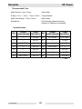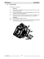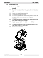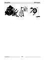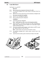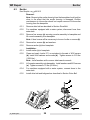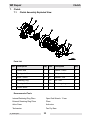
1
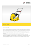
www.wackergroup.com
0111922
004
1004
en
Single Direction
Plates
WP 1550A/AW
WP 1550R/RW
WP 1550V/VW
WP 1550/W
WP 1540A/AW
WP 1540/W
REPAIR MANUAL
0
1
1
1
9
2
2
WP Repair
Table of Contents
1.
Foreword
3
2.
Safety Information
6
3.
4.
5.
2.1
Laws Pertaining to Spark Arresters ...................................................... 6
2.2
Operating Safety .................................................................................. 7
2.3
Operator Safety while using Internal Combustion Engines .................. 8
2.4
Service Safety ...................................................................................... 9
Technical Data
10
3.1
WP 1550A/AW ................................................................................... 10
3.2
WP 1550R/RW ................................................................................... 11
3.3
WP 1550V/VW ................................................................................... 12
3.4
WP 1540A/AW ................................................................................... 13
3.5
WP 1550/W ........................................................................................ 14
3.6
WP 1540/W ........................................................................................ 15
General
16
4.1
Application .......................................................................................... 16
4.2
General Description ............................................................................ 16
4.3
Periodic Maintenance Schedule ......................................................... 17
Baseplate
18
5.1
Exploded View .................................................................................... 18
5.2
Guide Handle ..................................................................................... 21
5.3
Frame-Lifting Cage ............................................................................. 22
5.4
Drive Belt ............................................................................................ 23
5.5
Engine ................................................................................................ 25
wc_br0111922004enTOC.fm
1
Table of Contents
6.
Exciter
6.1
6.2
6.3
6.4
7.
Exciter Exploded View .........................................................................26
Lower Belt Guard ................................................................................28
Exciter .................................................................................................29
Exciter Components ............................................................................30
33
Clutch Assembly Exploded View .........................................................33
Clutch ..................................................................................................34
Clutch Components .............................................................................35
Clutch Engagement Speed Test .........................................................36
Water System
8.1
9.
26
Clutch
7.1
7.2
7.3
7.4
8.
WP Repair
37
Water System Exploded View .............................................................37
Troubleshooting
wc_br0111922004enTOC.fm
39
2
CALIFORNIA
Proposition 65 Warning:
Engine exhaust, some of its constituents, and certain vehicle
components contain or emit chemicals known to the State of California
WARNING to cause cancer and birth defects or other reproductive harm.
1.
Foreword
This manual provides information and procedures to safely operate
and maintain this Wacker model. For your own safety and protection
from injury, carefully read, understand and observe the safety
instructions described in this manual.
Keep this manual or a copy of it with the machine. If you lose this
manual or need an additional copy, please contact Wacker
Corporation. This machine is built with user safety in mind; however,
it can present hazards if improperly operated and serviced. Follow
operating instructions carefully! If you have questions about operating
or servicing this equipment, please contact Wacker Corporation.
The information contained in this manual was based on machines in
production at the time of publication. Wacker Corporation reserves the
right to change any portion of this information without notice.
All rights, especially copying and distribution rights, are reserved.
Copyright 2004 by Wacker Corporation.
No part of this publication may be reproduced in any form or by any
means, electronic or mechanical, including photocopying, without
express written permission from Wacker Corporation.
Any type of reproduction or distribution not authorized by Wacker
Corporation represents an infringement of valid copyrights and will be
prosecuted. We expressly reserve the right to make technical
modifications, even without due notice, which aim at improving our
machines or their safety standards.
wc_si000083gb.fm
3
Notes:
wc_si000083gb.fm
4
This manual covers machines with Item Number:
0007576, 0007576, 0007577, 0007578, 0007578, 0007579, 0007579,
0007580, 0007581, 0007581, 0008060, 0008061, 0009324, 0009325,
0009326, 0009327, 0009472, 0009486
Operating / Parts Information
You must be familiar with the operation of this machine before you
attempt to troubleshoot or make any repairs to it. Basic operating and
maintenance procedures are described in the Operator’s Manual
supplied with the machine. Keep a copy of it with the machine at all
times. Use the separate Parts Book supplied with the machine to order
replacement parts. If either of the documents becomes lost, please
contact Wacker Corporation to order a replacement.
Damage caused by misuse or neglect of the unit should be brought to
the attention of the operator, to prevent similar occurrences from
happening in the future.
This manual provides information and procedures to safely repair and
maintain the above Wacker model(s). For your own safety and
protection from injury, carefully read, understand, and observe all
instructions described in this manual. THE INFORMATION
CONTAINED IN THIS MANUAL IS BASED ON MACHINES
MANUFACTURED UP TO THE TIME OF PUBLICATION. WACKER
CORPORATION RESERVES THE RIGHT TO CHANGE ANY
PORTION OF THIS INFORMATION WITHOUT NOTICE.
wc_si000083gb.fm
5
Safety Information
2.
WP Repair
Safety Information
This manual contains DANGER, WARNING, CAUTION, and NOTE
callouts which must be followed to reduce the possibility of personal
injury, damage to the equipment, or improper service.
This is the safety alert symbol. It is used to alert you to potential
personal injury hazards. Obey all safety messages that follow this
symbol to avoid possible injury or death.
DANGER indicates an imminently hazardous situation which, if not
avoided, will result in death or serious injury.
DANGER
WARNING indicates a potentially hazardous situation which, if not
avoided, could result in death or serious injury.
WARNING
CAUTION indicates a potentially hazardous situation which, if not
avoided, may result in minor or moderate injury.
CAUTION
CAUTION: Used without the safety alert symbol, CAUTION indicates
a potentially hazardous situation which, if not avoided, may result in
property damage.
Note: Contains additional information important to a procedure.
2.1
Laws Pertaining to Spark Arresters
Notice: State Health Safety Codes and Public Resources Codes
specify that in certain locations spark arresters be used on internal
combustion engines that use hydrocarbon fuels. A spark arrester is a
device designed to prevent accidental discharge of sparks or flames
from the engine exhaust. Spark arresters are qualified and rated by
the United States Forest Service for this purpose.
In order to comply with local laws regarding spark arresters, consult
the engine distributor or the local Health and Safety Administrator.
wc_si000083gb.fm
6
WP Repair
2.2
Safety Information
Operating Safety
Familiarity and proper training are required for the safe operation of
equipment! Equipment operated improperly or by untrained personnel
can be dangerous! Read the operating instructions contained in both
WARNING this manual and the engine manual and familiarize yourself with the
location and proper use of all controls. Inexperienced operators should
receive instruction from someone familiar with the equipment before
being allowed to operate the machine.
wc_si000083gb.fm
2.2.1
NEVER allow anyone to operate this equipment without proper
training. People operating this equipment must be familiar with the
risks and hazards associated with it.
2.2.2
NEVER touch the engine or muffler while the engine is on or
immediately after it has been turned off. These areas get hot and may
cause burns.
2.2.3
NEVER use accessories or attachments that are not recommended by
Wacker. Damage to equipment and injury to the user may result.
2.2.4
NEVER operate the machine with the beltguard missing. Exposed
drive belt and pulleys create potentially dangerous hazards that can
cause serious injuries.
2.2.5
NEVER leave machine running unattended.
2.2.6
ALWAYS be sure operator is familiar with proper safety precautions
and operation techniques before using machine.
2.2.7
ALWAYS wear protective clothing appropriate to the job site when
operating equipment.
2.2.8
ALWAYS wear hearing protection when operating equipment.
2.2.9
ALWAYS close fuel valve on engines equipped with one when
machine is not being operated.
2.2.10
ALWAYS store equipment properly when it is not being used.
Equipment should be stored in a clean, dry location out of the reach of
children.
2.2.11
ALWAYS operate machine with all safety devices and guards in place
and in working order. DO NOT modify or defeat safety devices. DO
NOT operate machine if any safety devices or guards are missing or
inoperative.
2.2.12
ALWAYS read, understand, and follow procedures in Operator's
Manual before attempting to operate equipment.
7
Safety Information
2.3
WP Repair
Operator Safety while using Internal Combustion Engines
DANGER
Internal combustion engines present special hazards during operation
and fueling! Read and follow warning instructions in engine owner's
manual and safety guidelines below. Failure to follow warnings and
safety guidelines could result in severe injury or death.
2.3.1
DO NOT run machine indoors or in an enclosed area such as a deep
trench unless adequate ventilation, through such items as exhaust
fans or hoses, is provided. Exhaust gas from the engine contains
poisonous carbon monoxide gas; exposure to carbon monoxide can
cause loss of consciousness and may lead to death.
2.3.2
DO NOT smoke while operating machine.
2.3.3
DO NOT smoke when refueling engine.
2.3.4
DO NOT refuel hot or running engine.
2.3.5
DO NOT refuel engine near open flame.
2.3.6
DO NOT spill fuel when refueling engine.
2.3.7
DO NOT run engine near open flames.
2.3.8
ALWAYS refill fuel tank in well-ventilated area.
2.3.9
ALWAYS replace fuel tank cap after refueling.
2.3.10 ALWAYS check fuel lines and fuel tank for leaks and cracks before
starting engine. Do not run machine if fuel leaks are present or fuel
lines are loose.
wc_si000083gb.fm
8
WP Repair
2.4
Safety Information
Service Safety
Poorly maintained equipment can become a safety hazard! In order
for the equipment to operate safely and properly over a long period of
time, periodic maintenance and occasional repairs are necessary.
WARNING
wc_si000083gb.fm
2.4.1
DO NOT attempt to clean or service machine while it is running.
Rotating parts can cause severe injury.
2.4.2
DO NOT crank a flooded engine with the spark plug removed on
gasoline-powered engines. Fuel trapped in the cylinder will squirt out
the spark plug opening.
2.4.3
DO NOT test for spark on gasoline-powered engines, if engine is
flooded or the smell of gasoline is present. A stray spark could ignite
fumes.
2.4.4
DO NOT use gasoline or other types of fuels or flammable solvents to
clean parts, especially in enclosed areas. Fumes from fuels and
solvents can become explosive.
2.4.5
ALWAYS keep area around muffler free of debris such as leaves,
paper, cartons, etc. A hot muffler could ignite them, starting a fire.
2.4.6
ALWAYS replace worn or damaged components with spare parts
designed and recommended by Wacker.
2.4.7
ALWAYS disconnect spark plug on machines equipped with gasoline
engines, before servicing, to avoid accidental start-up.
2.4.8
ALWAYS keep machine clean and labels legible. Replace all missing
and hard-to-read labels. Labels provide important operating
instructions and warn of dangers and hazards.
9
Technical Data
3.
WP Repair
Technical Data
3.1 WP 1550A/AW
WP 1550A/AW
0007576, 0007579, 0009486
Plate
Operating Weight
Water Tank Capacity
Exciter Speed
Exciter Lubrication
Dimensions
kg (lbs.)
86 (190)
l (qts.)
10.4 (11.0)
rpm / belt
5800
ml (oz.)
150 (5)
Automatic Transmission Fluid
Dextron III / Mercon or equivalent
mm (in.)
875 (35) x 500 (20) x 965 (38)
WP 1550A/AW
0007576, 0007579, 0009486
Engine
Engine Make
Honda
Engine Model
GX 160 K1 QWXZ
Rated Power
Spark Plug
Electrode Gap
kW (Hp)
4.1 (5.5)
type
NGK BPR 6ES
mm (in.)
0.7 – 0.8 (0.028 – 0.031)
Engine Speed - full
rpm
3600 ± 50
Engine Speed - idle
rpm
1600 ± 100
Clutch Engagement
rpm
2100
Air Cleaner
type
Dual Element
oil grade
SAE 10W30
Engine Lubrication
service class
SG or SF
Engine Oil Capacity
ml (oz.)
600 (20)
Engine Oil Capacity
ml (oz.)
Regular unleaded gasoline
Fuel Tank Capactity
l (qts.)
3.7 (3.9)
Valve Clearance (cold)
wc_td000080gb.fm
mm (in.)
Inlet: 0.15 (0.006)
Outlet: 0.20 (0.008)
10
WP Repair
3.2
Technical Data
WP 1550R/RW
WP 1550R/RW
0007578, 0007581
Plate
Operating Weight
Water Tank Capacity
Exciter Speed
Exciter Lubrication
Dimensions
kg (lbs.)
88 (194)
l (qts.)
10.4 (11.0)
rpm / belt
5800
ml (oz.)
150 (5)
Automatic Transmission Fluid
Dextron III / Mercon or equivalent
mm (in.)
686 (27) x 508 (62) x 965 (38)
WP 1550R/RW
0007578, 0007581
Engine
Engine Make
Robin
Engine Model
EH17
Rated Power
kW (Hp)
4.5 (6.0)
Engine Speed - full
rpm
3600 ± 100
Engine Speed - idle
rpm
1600 ± 100
Clutch Engagement
rpm
2100
Spark Plug
type
NGK B6HS
Electrode Gap
Air Cleaner
Engine Lubrication
Engine Oil Capacity
Fuel
Fuel Tank Capactity
Valve Clearance (cold)
wc_td000080gb.fm
mm (in)
0.5–0.76 (0.020–0.030)
type
Dual Element
oil grade
SAE 10W30
service class
SC or higher
ml (oz.)
600 (20)
type
Regular unleaded gasoline
l (qts.)
3.6 (3.8)
mm (in.)
Inlet: 0.085–0.115 (0.0033–0.0045)
Outlet: 0.085–0.115 (0.0033–0.0045)
11
Technical Data
3.3
WP Repair
WP 1550V/VW
WP 1550V/VW
0007577, 0007580
Plate
Operating Weight
Water Tank Capacity
Exciter Speed
Exciter Lubrication
Dimensions
kg (lbs.)
91 (200)
l (qts.)
10.4 (11.0)
rpm / belt
5800
ml (oz.)
150 (5)
Automatic Transmission Fluid
Dextron III / Mercon or equivalent
mm (in.)
686 (27) x 508 (62) x 965 (38)
WP 1550V/VW
0007577, 0007580
Engine
Engine Make
Vanguard
Engine Model
115432-0047
Rated Power
kW (Hp)
4.5 (6.0)
Engine Speed - full
rpm
3600 ± 100
Engine Speed - idle
rpm
1400 ± 100
Clutch Engagement
rpm
2100
Spark Plug
type
Champion 12VC
Electrode Gap
Air Cleaner
Engine Lubrication
Engine Oil Capacity
Fuel
Fuel Tank Capactity
Valve Clearance (cold)
wc_td000080gb.fm
mm (in)
0.76 (0.030)
type
Dual Element
oil grade
SAE 10W30
service class
SG, SF or SE
ml (oz.)
600 (20)
type
Regular unleaded gasoline
l (qts.)
4.0 (4.2)
mm (in.)
Inlet: 0.05–0.08 (0.002–0.003)
Outlet: 0.05–0.08 (0.002–0.003)
12
WP Repair
3.4
Technical Data
WP 1540A/AW
WP 1540A/AW
0008060, 0008061, 0009472
Plate
Operating Weight
Water Tank Capacity
Exciter Speed
Exciter Lubrication
Dimensions
kg (lbs.)
86 (190)
l (qts.)
10.4 (11.0)
rpm / belt
5800
ml (oz.)
150 (5)
Automatic Transmission Fluid
Dextron III / Mercon or equivalent
mm (in.)
686 (27) x 400 (16) x 965 (38)
WP 1540A/AW
0008060, 0008061, 0009472
Engine
Engine Make
Honda
Engine Model
GX 160 K1 QX2
Rated Power
kW (Hp)
4.1 (5.5)
Engine Speed - full
rpm
3600 ± 100
Engine Speed - idle
rpm
1600 ± 100
Clutch Engagement
rpm
2100
Spark Plug
type
NGK BPR 6ES
Electrode Gap
Air Cleaner
Engine Lubrication
Engine Oil Capacity
Fuel
Fuel Tank Capactity
Valve Clearance (cold)
wc_td000080gb.fm
mm (in)
0.7–0.8 (0.028–0.031)
type
Dual Element
oil grade
SAE 10W30
service class
SG or SF
ml (oz.)
600 (20)
type
Regular unleaded gasoline
l (qts.)
3.7 (3.9)
mm (in.)
Inlet: 0.15 (0.006)
Outlet: 0.20 (0.008)
13
Technical Data
3.5
WP Repair
WP 1550/W
WP 1550, WP 1550 W
0009325, 0009324
Plate
Operating Weight
Water Tank Capacity
Exciter Speed
Exciter Lubrication
88 (194)
kg (lbs.)
l (qts.)
10.4 (11.0)
rpm / belt
5800 ± 100
150 (5)
Automatic Transmission Fluid
Dextron III / Mercon or equivalent
ml (oz.)
WP 1550, WP 1550 W
0009325, 0009324
Engine
Engine Make
Wacker
Engine Model
WM170
Rated Power
4.5 (6.0)
kW (Hp)
Engine Speed - full
rpm
3600 ± 50
Engine Speed - idle
rpm
1400 ± 100
Clutch Engagement
rpm
2100
Spark Plug
type
NGK BR6HS, Champion RL86C
Electrode Gap
Air Cleaner
Engine Lubrication
Engine Oil Capacity
Fuel
Fuel Tank Capactity
Valve Clearance (cold)
Inlet:
Outlet:
wc_td000080gb.fm
0.6–0.7 (0.024–0.028)
mm (in)
Dual Element
type
oil grade
SAE 10W30
service class
SE or higher
600 (20)
ml (oz.)
Regular unleaded gasoline
type
3.6 (3.8)
l (qts.)
mm (in.)
0.07–0.13 (0.003–0.005)
0.17–0.23 (0.007–0.009)
14
WP Repair
3.6
Technical Data
WP 1540/W
WP 1540, WP 1540 W
0009237, 0009236
Plate
Operating Weight
Water Tank Capacity
Exciter Speed
Exciter Lubrication
Dimensions
kg (lbs.)
86 (190)
l (qts.)
10.4 (11.0)
rpm / belt
5800
ml (oz.)
150 (5)
Automatic Transmission Fluid
Dextron III / Mercon or equivalent
mm (in.)
686 (27) x 400 (16) x 965 (38)
WP 1540, WP 1540 W
0009327, 0009326
Engine
Engine Make
Wacker
Engine Model
WM170
Rated Power
kW (Hp)
4.5 (6.0)
Engine Speed - full
rpm
3600 ± 50
Engine Speed - idle
rpm
1400 ± 100
Clutch Engagement
rpm
2100
Spark Plug
type
NGK BR6HS, Champion RL86C
Electrode Gap
Air Cleaner
Engine Lubrication
Engine Oil Capacity
Fuel
Fuel Tank Capactity
Valve Clearance (cold)
Inlet:
Outlet:
wc_td000080gb.fm
mm (in)
0.6–0.7 (0.024–0.028)
type
Dual Element
oil grade
SAE 10W30
service class
SE or higher
ml (oz.)
600 (20)
type
Regular unleaded gasoline
l (qts.)
3.6 (3.8)
mm (in.)
0.07–0.13 (0.003–0.005)
0.17–0.23 (0.007–0.009)
15
General
4.
WP Repair
General
4.1
Application
This plate is designed for compacting loose, granular soils, gravel, and
paving stones. It is intended to be used in confined areas and areas
next to structures such as walls, curbs, and foundations. Plates
equipped with water tanks can be used for compacting asphalt.
This plate is not recommended for compacting cohesive soils with a
heavy clay content. For cohesive soil, use a vibratory rammer or
sheepsfoot roller.
4.2
General Description
For the WP product line of vibroplates, engine power is transferred to
the exciter through a centrifugal clutch and V-belt. The splashlubricated exciter consists of an eccentric weighted, one-piece shaft
that is supported on two roller bearings. The shaft assembly is
mounted in an aluminum housing. The exciter vibrates at 6000 times
per minute and produces approximately 15 kN (3375 pounds) of
centrifugal force.
wc_tx000215gb.fm
16
WP Repair
4.3
General
Periodic Maintenance Schedule
Daily
before
starting
Check fuel level.
•
Check engine oil level.
•
Inspect fuel lines.
•
Inspect air filter. Replace as needed.
•
Check and tighten external hardware.
•
Check and adjust drive belt.
After
first
20 hrs.
Every
2 weeks
or
50 hrs.
•
•
Clean air cleaner elements.
•
Inspect shockmounts for damage.
•
Change engine oil.
•
Every
month
or
100 hrs.
Every
year
or
300 hrs.
•
Clean engine cooling fins.
•
Clean sediment cup / fuel filter.
•
Check and clean spark plug.
•
Check and adjust valve clearance.
•
Change exciter oil.
•
wc_tx000215gb.fm
17
Baseplate
5.
WP Repair
Baseplate
5.1
wc_tx000216gb.fm
Exploded View
18
WP Repair
Baseplate
Parts List
Ref.
Description
Qty
Ref.
Description
Qty
1
Frame - lifting cage
1
22
Bushing - handle mount
2
2
Screw M12x35
4
23
Bushing - nylon
2
3
Washer - lock A12
12
24
Shockmount
4
4
Screw M4x6 (Honda only)
2
25
Baseplate
1
5
Baffle - exhaust (Honda only)
1
26
Beltguard - lower
1
6
Engine
1
27
Screw M8-20
7
7
Plate - beltguard
1
28
Exciter
1
8
Washer - lock B8
15
29
Washer
4
9
Screw 5/16-24x3/4
4
30
Screw M16x40
4
10
Key
1
31
Nut-lock M12
4
11
Clutch - adjustable
1
32
Screw M12x25
4
12
Washer - steel
1
33
Handle - lifting
2
13
Screw 5/16-24x7/8
1
34
Plug - Cap #1
6
14
Belt-V A27
1
35
Shockmount
2
15
O-Ring
4
36
Grommet
1
16
Beltguard - upper
1
37
Console
1
17
Screw M8x65
2
38
Stud M8x35
4
18
Screw M8x75
2
39
Nut-lock M8
4
19
Guide handle
4
40
Screw M6x12
1
20
Screw M12x60
2
41
Strap - muffler support
1
21
Washer - steel
4
42
Screw
1
wc_tx000216gb.fm
19
Baseplate
WP Repair
Recommended Tools
Allen Wrench: 6 mm, 14 mm
Gear Puller
Socket: 1/2 in., 1-1/4 in., 13 mm, 19 mm
Torque Wrench
Open End Wrench: 13 mm, 19 mm
Arbor Press
Screwdriver
Oil: Automatic transmission fluid
(Dextron III, Mercon or equivalent)
* Assembly Notes
Ref.
Sealant
Loctite (Omnifit)
Torque
Nm (ft.lbs.)
Ref.
Sealant
Loctite (Omnifit)
Torque
Nm (ft.lbs.)
2
---
73 (54)
30
271 (1550)
210 (155)
9
---
20 (15)
31
---
73 (54)
13
243 (1350)
20 (15)
32
---
73 (54)
17
---
20 (15)
38
243 (1350)
---
18
---
20 (15)
39
---
20 (15)
73 (54)
40
---
4.5 (40**)
20 (15)
42
---
10.2 (90**)
20
27
243 (1350)
** in.lbs.
wc_tx000216gb.fm
20
WP Repair
5.2
Baseplate
Guide Handle
See Graphic: wc_gr001007
Removal:
5.2.1
Remove M12 screws (20) on each side of machine and remove guide
handle assembly (19).
5.2.2
Remove washers (21) and bushings (22 and 23) from handle. Press
bushings from handle if necessary.
5.2.3
Replace shockmounts (35) if they appear cracked or damaged. Use a
channel-lock pliers to unscrew shockmounts from console (37).
Installation:
wc_tx000216gb.fm
5.2.1
Install shockmounts (35) on console.
5.2.2
Install handle on console using washers (21), bushings (22 and 23)
and screws (20). Tighten screws to 73 Nm (54 ft.lbs.).
21
Baseplate
5.3
WP Repair
Frame-Lifting Cage
See Graphic: wc_gr001008
Removal:
5.3.1
For machines equipped with a water system, disconnect hose from
water tank. Remove two screws and washers at the rear of the water
tank.
5.3.2
Remove four screws (2) and washers (3).
5.3.3
Lift frame assembly (1) from machine.
5.3.4
For machines equipped with a water system, remove two screws (27)
and washers (8) to remove water tank from lifting cage.
Installation:
wc_tx000216gb.fm
5.3.1
For water system machines, install water tank, washers (8) and screws
(27). Tighten screws to 20 Nm (15 ft.lbs.).
5.3.2
Install frame assembly (1), washers (3) and screws (2). Tighten screws
to 73 Nm (54 ft.lbs.).
5.3.3
For water system machines, install two screws and washers at rear of
tank. Tighten screws to 8.1 Nm (6 ft.lbs.).
5.3.4
Connect hose to water tank.
22
WP Repair
5.4
Baseplate
Drive Belt
See Graphic: wc_gr001009
Removal:
5.4.1
Pivot guide handle forward.
5.4.2
Remove screws (17 and 18) to remove beltguard (16). O-rings (15) will
remain on screws, and keep screws captive in the belt guard.
5.4.3
Remove four nuts (a) and lock washers holding pulley halves (b) and
spacers (c) together.
5.4.4
Remove outer pulley half to remove drive belt from exciter pulley and
machine.
Installation:
5.4.1
Install belt on exciter pulley.
5.4.2
Install three spacers (c) and outer pulley half with belt between pulley
halves (b).
5.4.3
Install lock washers and nuts (a). Tighten nuts securely.
5.4.4
Pivot guide handle rearward to operating position.
Adjustment:
After the first 20 hours of use, check belt deflection. Drive belt
deflection should be 6–9 mm (1/4 to 3/8 in.) half way between the
clutch pulley and the exciter pulley.
Two or three spacers with new factory belts should provide the correct
tension.
To increase belt tension (reduce amount of deflection):
wc_tx000216gb.fm
5.4.1
Remove nuts (a) and lock washers. Remove outer pulley half and one
spacer.
5.4.2
Install outer pulley half, then the unused spacer. Secure with lock
washers and nuts (a).
5.4.3
Check belt deflection again. If necessary, remove another spacer from
between pulley halves and put outside of pulley halves.
5.4.4
Install belt guard (16), O-rings (15) and screws (17 and 18). Tighten
screws to 20 Nm (15 ft.lbs.).
23
Baseplate
wc_tx000216gb.fm
WP Repair
24
WP Repair
5.5
Baseplate
Engine
See Graphic: wc_gr001010
Removal:
5.5.1
Remove lifting cage frame as shown in Section Frame - Lifting Cage.
5.5.2
Remove drive belt as described in Section Drive Belt .
5.5.3
Remove screw (27) and washer (8).
5.5.4
Remove four M8 lock nuts (39) and washers (8).
5.5.5
Carefully lift the engine (6) from the console.
5.5.6
If necessary, remove clutch from engine as described in Section
Clutch.
Installation:
5.5.1
If removed, install clutch on engine as described in Section Clutch.
5.5.2
If removed, apply Loctite 242 or equivalent to lower threads of M8x35
studs (38) and install in console securely.
Note: For Honda and Robin engines, use the inner 4-hole pattern. For
Vanguard engines, use outer hole pattern at the rear and inner hole
pattern at the front of the machine.
wc_tx000216gb.fm
5.5.3
Install engine (6), four washers (8) and four lock nuts (39). Tighten lock
nuts to 20 Nm (15 ft.lbs.).
5.5.4
Install washer (8) and screw (27) in beltguard plate. Tighten screw to
20 Nm (15 ft.lbs.).
5.5.5
Install drive belt and beltguard as described in Section Drive Belt.
5.5.6
Install lifting cage frame as shown in Section Frame - Lifting Cage.
25
Exciter
6.
WP Repair
Exciter
6.1
wc_tx000217gb.fm
Exciter Exploded View
26
WP Repair
Exciter
Parts List
Ref.
Description
Qty
Ref.
Description
Qty
1
Screw M8x30
6
6
Housing - exciter
1
2
Washer - lock B8
6
7
Shaft - exciter
1
3
Holder - bearing w/o hole
1
8
Holder - bearing w/ hole
1
4
Bearing - roller
2
9
Seal - shaft
1
5
O-Ring
2
10
Pulley - exciter
1
Recommended Tools
Allen Wrench: 14 mm
Bearing and Seal Driver Set
Socket: 13 mm
Arbor Press
Open End Wrench: 1-1/4 in.
Hammer
Screwdriver
Blunt End Punch
Bearing Puller
Oil: Automatic transmission fluid
(Dextron III, Mercon or equivalent)
Torque Wrench
wc_tx000217gb.fm
Ref.
Sealant
Loctite (Omnifit)
Torque
Nm (ft.lbs.)
1
---
30 (22)
27
Exciter
6.2
WP Repair
Lower Belt Guard
See Graphic: wc_gr001012
Removal:
6.2.1
Remove drive belt as described in Section Drive Belt.
6.2.2
For machines equipped with a water system, disconnect hose from
water tank.
6.2.3
Remove four screws (a) securing console assembly to baseplate and
lift console assembly from baseplate.
6.2.4
Remove four screws (b) and washers.
6.2.5
Remove belt guard (c) from baseplate.
Installation:
6.2.1
Install belt guard (c) to baseplate.
Note: Install washers with concave side towards machine.
6.2.2
Apply Loctite 243 or equivalent to threads of four M8 screws (b) and to
screw holes. Install four conical washers and screws (b). Tighten
screws to 20 Nm (15 ft.lbs.).
6.2.3
Lift console assembly onto baseplate. Install washers and M12 screws
(a). Tighten screws to 73 Nm (54 ft.lbs.).
Note: Install washers with concave side towards console.
wc_tx000217gb.fm
6.2.4
For machines equipped with a water system, connect hose to the
water tank.
6.2.5
Install drive belt and belt guard as described in Section Drive Belt.
28
WP Repair
6.3
Exciter
Exciter
See Graphic: wc_gr001013
Removal:
Note: Removing the exciter housing from the baseplate should only be
done in the event that the exciter housing is damaged. Routine
maintenance to the exciter should not require removal of the exciter
housing from the baseplate.
6.3.1
Remove drive belt as described in Section Drive Belt.
6.3.2
For machines equipped with a water system, disconnect hose from
water tank.
6.3.3
Remove four screws (a) securing console assembly to baseplate and
lift console assembly from baseplate.
Note: A heat source will be necessary to loosen Loctite on screws (b).
6.3.4
Remove four screws (b) and washers.
6.3.5
Remove exciter (c) from baseplate.
Installation:
6.3.1
Install exciter (c) to baseplate.
6.3.2
Clean and apply Loctite 271 or equivalent to threads of M16 screws
(b). Install four washers and screws (b). Tighten screws to 210 Nm
(155 ft.lbs.).
Note: Install washers with concave side towards console.
wc_tx000217gb.fm
6.3.3
Lift console assembly onto baseplate. Install washers and M12 screws
(a). Tighten screws to 73 Nm (54 ft.lbs.).
6.3.4
For machines equipped with a water system, connect hose to the
water tank.
6.3.5
Install drive belt and beltguard as described in Section Drive Belt.
29
Exciter
6.4
WP Repair
Exciter Components
See Graphic: wc_gr001014
Disassembly:
6.4.1
If the exciter housing is damaged, remove the exciter as described in
Section Exciter.
Note: Pulley threads are left hand threads.
6.4.2
Remove the exciter pulley (12) using a 1-1/4 in. socket.
Note: If pulley does not loosen from shaft at this point, remove shaft
assembly from housing and then remove pulley.
CAUTION: Exciter shaft is not retained at pulley end, shaft can fall
from housing when bearing holder is removed.
6.4.3
Remove three M8 screws (1) and washers (2) securing bearing holder
(3) and drain oil into pan.
6.4.4
Remove exciter shaft (9) with inner roller bearing races (d).
6.4.5
Remove three M8 screws (1) and washers (2) securing shaft-end
bearing holder (10) and remove holder.
6.4.6
Remove seal (11) from shaft-end bearing holder.
Note: Keep outer and inner bearing races together as matched sets
and replace them as sets.
6.4.7
Remove roller bearings outer races (e) and O-rings (5) from bearing
holders (3 and 10) using bearing puller tool.
6.4.8
Remove bearing inner races (d) using a bearing puller tool.
Note: It is only necessary to remove inner races if bearing is to be
replaced. Heat inner races to aid removal. If bearing is not being
replaced, be sure to match inner races with mating outer races during
assembly.
wc_tx000217gb.fm
30
WP Repair
Exciter
See Graphic: wc_gr001028
Assembly:
6.4.1
Clean the inside of the exciter housing and bearing housings
thoroughly. Make sure vent passage (a) in shaft is free of any
obstruction.
6.4.2
If replacing bearings, use an appropriate size and length of pipe to
press new inner races (b) onto exciter shaft as shown.
Note: Keep outer and inner bearing races together as a set.
6.4.3
Apply automatic transmission fluid to outer bearing races (c). Use an
appropriate size disk from bearing and seal driver set to press outer
bearing races (c) into bearing holders (3 and 10).
6.4.4
Install seal in bearing holder (3) approximately 2.5 mm (0.1 in.) below
top of bore.
Note: Lips of seal should be towards roller bearing.
6.4.5
Apply petroleum jelly to O-rings (5) and seal lips. Install O-rings on
bearing holders.
6.4.6
Apply Loctite 243 or equivalent to threads of three M8 screws (1) and
to screw holes. Install bearing holder (10) without hole using screws
(1) and washers (2). Tighten screws to 30 Nm (22 ft.lbs.).
6.4.7
Put the exciter assembly in a vertical position and install exciter shaft
(9) into case.
6.4.8
Fill exciter with oil, before operating. See Technical Data for oil quantity
and type.
6.4.9
Apply Loctite 243 or equivalent to threads of remaining three M8
screws (1) and to screw holes. Install bearing holder (3) with hole
using screws (1) and washers (2). Use care not to damage seal lips.
Tighten screws to 30 Nm (22 ft.lbs.).
6.4.10
Install exciter pulley onto shaft.
Note: Threads are left handed.
6.4.11
wc_tx000217gb.fm
Install exciter assembly to loose frame as described in Section Exciter.
31
Exciter
wc_tx000217gb.fm
WP Repair
32
WP Repair
7.
Clutch
Clutch
7.1 Clutch Assembly Exploded View
Parts List
Ref.
Description
Qty
Ref.
Description
Qty
1
Clutch hub
1
7
Spacer - clutch
3
2
Spring - clutch
3
8
Pulley - clutch
1
3
Shoe - clutch
3
9
Washer - lock
4
4
Retaining ring
1
10
Nut - hex
4
5
Bearing - ball
1
11
Retaining ring
1
6
Clutch drum
1
Recommended Tools
Internal Retaining Ring Pliers
Open End Wrench: 13 mm
External Retaining Ring Pliers
Pliers
Arbor Press
Anti-seize
Tachometer
Two Pry Bars
wc_tx000218gb.fm
33
Clutch
7.2
WP Repair
Clutch
See Graphic: wc_gr001016
Removal:
7.2.1
Remove drive belt as described in Section Drive Belt.
7.2.2
Remove screw (a) and washer securing clutch (b) to engine shaft. Pry
clutch from engine shaft using two pry bars. Use care not to damage
clutch while prying.
7.2.3
Remove key (c).
7.2.4
If necessary, remove four screws (d) and washers and screw (e) and
washer to remove beltguard plate (f).
Installation:
wc_tx000218gb.fm
7.2.1
If removed, install beltguard plate (f) using washers and screws (d and
e). Tighten screws to 20 Nm (15 ft.lbs.).
7.2.2
Install key (c) on engine shaft. Apply anti-seize compound to shaft.
7.2.3
Apply Loctite 242 to threads of screw (a). Secure clutch assembly (b)
to engine shaft using washer and screw (a). Tighten screw to 20 Nm
(15 ft.lbs.).
7.2.4
Install drive belt and beltguard as described in Section Drive Belt.
34
WP Repair
7.3
Clutch
Clutch Components
See Graphic: wc_gr001017
Disassembly:
7.3.1
Remove clutch as described in Section Clutch.
7.3.2
Remove retaining ring (11).
7.3.3
Support clutch drum assembly on edge as shown (a) and press out
clutch hub assembly.
7.3.4
Remove bearing retaining ring (4).
7.3.5
Support clutch drum (6) and press out bearing (5).
7.3.6
Remove springs (2) with pliers to remove shoes (3) from hub (1).
Assembly:
wc_tx000218gb.fm
7.3.1
Press new bearing (5) into clutch drum (6). Secure bearing with
retaining ring (4).
7.3.2
Assemble shoes (3) and springs (2) on clutch hub (1). Press assembly
into clutch drum and secure with retaining ring (11).
7.3.3
Install clutch on engine shaft as described in Section Clutch.
35
Clutch
7.4
WP Repair
Clutch Engagement Speed Test
Take care when testing machine with beltguard removed to avoid
loose clothing, jewelery, long hair, etc., from getting caught in rotating
parts. Replace beltguard after testing and before operating machine.
WARNING
wc_tx000218gb.fm
7.4.1
Remove beltguard as described in Section Drive Belt.
7.4.2
Put machine on a rubber test mat to prevent it from moving.
7.4.3
Start engine and allow it to warm up.
7.4.4
Pull throttle to full speed. Allow the exciter to reach full speed for a few
seconds, then return to idle.
7.4.5
Attach tachometer and slowly increase engine speed. Note the engine
speed reading when clutch pulley starts to rotate. Correct clutch speed
is 2100 ± 100 RPM.
7.4.6
If clutch engagement is below 2000 RPM, check for weak springs. If
clutch engagement is over 2200 RPM, clutch may be worn and require
replacement, or exciter belt may be binding.
36
WP Repair
8.
Water System
Water System
8.1
wc_tx000219gb.fm
Water System Exploded View
37
Water System
WP Repair
Parts List
Ref.
Description
Qty
Ref.
Description
Qty
1
Cap-water tank
1
9
Screw M8 x 25
3
2
Screw M8 x 40
2
10
Washer-lock B8
4
3
Washer B8.4
2
11
Washer B8.4
3
4
Tank-water
1
12
Manifold-water tank
1
5
Valve-shutoff
1
13
Hose
1
6
Bushing-tank valve
1
14
Screw M8 x 20
2
7
Filter-water
1
15
Plug 1/4-18 NPT
2
8
Seal-ring
1
Recommended Tools
Socket: 13 mm, 19 mm
Pliers
Wrench: 13 mm
* Assembly Notes
Ref.
Sealant
Loctite (Omnifit)
Torque
Nm (ft.lbs.)
Ref.
Sealant
Loctite (Omnifit)
Torque
Nm (ft.lbs.)
2
---
8.1 (6)
14
---
20 (15)
9
243 (1350)
20 (15)
wc_tx000219gb.fm
38
WP Repair
9.
Troubleshooting
Troubleshooting
Problem / Symptom
Reason / Remedy
Plate does not develop full
speed. Poor compaction.
• Engine throttle control not completely open.
• Throttle control not adjusted correctly.
• Ground too wet, plate sticking. Allow soil to dry
before compacting.
• Drive belt loose or worn, slipping on pulleys. Adjust
or replace belt. Check that engine mounting bolts
are tight.
• Exciter bearings binding. Check condition and level
of oil in exciter. Add or change oil.
• Air filter clogged with dust, reducing engine performance. Clean or replace air filter.
• Engine speed too low. Check engine speed with
tachometer. Adjust or repair engine to run at correct
speed. Refer to engine manual.
Engine running, no vibration
• Engine throttle not open.
• Drive belt loose or broken. Adjust or replace.
• Clutch damaged. Inspect and replace clutch.
• Engine speed too low. Check engine speed.
• Too much oil in exciter. Adjust oil to correct level.
Plate jumps or compacts
unevenly.
wc_tx000219gb.fm
• Ground surface too hard.
• Shockmounts loose or damaged.
39
Troubleshooting
WP Repair
Notes:
wc_tx000219gb.fm
40
Threadlockers and Sealants
Threadlockers and Sealants
Threadlocking adhesives and sealants are specified throughout this
manual by a notation of “S” plus a number (S#) and should be used
where indicated. Threadlocking compounds normally break down at
temperatures above 175°C (350°F). If a screw or bolt is hard to
remove, heat it using a small propane torch to break down the sealant.
When applying sealants, follow instructions on container. The sealants
listed below are recommended for use on Wacker equipment.
TYPE
( ) = Europe
PART NO. SIZE
COLOR
USAGE
Loctite 222
Hernon 420
Omnifit 1150 (50M)
Purple
Low strength, for locking threads smaller than 6 mm
(1/4").
Hand tool removable.
Temp. range, -54 to 149°C (-65 to 300°F)
73287 - 10 ml
Hernon 423
Omnifit 1350 (100M)
Blue
Medium strength, for locking threads larger than
6 mm (1/4").
Hand tool removable.
Temp. range, -54 to 149°C (-65 to 300°F)
29311 - .5 ml
17380 - 50 ml
Loctite 271/277
Hernon 427
Omnifit 1550 (220M)
Red
High strength, for all threads up to 25 mm (1”).
Heat parts before disassembly.
Temp. range, -54 to 149°C (-65 to 300°F)
29312 - .5 ml
26685 - 10 ml
73285 - 50 ml
Loctite 290
Hernon 431
Omnifit 1710 (230LL)
Green
Medium to high strength, for locking preassembled
threads and for sealing weld porosity (wicking).
Gaps up to 0.13 mm (0.005")
Temp. range, -54 to 149°C (-65 to 300° F)
28824 - .5 ml
25316 - 10 ml
Loctite 609
Hernon 822
Omnifit 1730 (230L)
Green
Medium strength retaining compound for slip or press
fit of shafts, bearings, gears, pulleys, etc.
Gaps up to 0.13 mm (0.005")
Temp. range, -54 to 149°C (-65 to 300°F)
29314 - .5 ml
Loctite 545
Hernon 947
Omnifit 1150 (50M)
Brown
Hydraulic sealant
Temp. range, -54 to 149°C (-65 to 300°F)
79356 - 50 ml
Loctite 592
Hernon 920
Omnifit 790
White
Pipe sealant with Teflon for moderate pressures.
Temp. range, -54 to 149°C (-65 to 300°F)
26695 - 6 ml
73289 - 50 ml
Loctite 515
Hernon 910
Omnifit 10
Purple
Form-in-place gasket for flexible joints.
Fills gaps up to 1.3 mm (0.05")
Temp. range, -54 to 149°C (-65 to 300°F)
70735 - 50 ml
Loctite 496
Hernon 110
Omnifit Sicomet 7000
Clear
Instant adhesive for bonding rubber, metal and plastics; general purpose.
For gaps up to 0.15 mm (0.006")
Read caution instructions before using.
Temp. range, -54 to 82°C (-65 to 180°F)
52676 - 1 oz.
Threadlockers and Sealants
TYPE
( ) = Europe
Loctite Primer T
Hernon Primer 10
Omnifit VC Activator
COLOR
USAGE
Aerosol
Spray
Fast curing primer for threadlocking, retaining and
sealing compounds. Must be used with stainless steel
hardware. Recommended for use with gasket sealants.
PART NO. SIZE
2006124 6 oz.
Torque Values
Torque Values
Metric Fasteners (DIN)
TORQUE VALUES (Based on Bolt Size and Hardness)
8.8
10.9
WRENCH SIZE
12.9
Size
ft.lb.
Nm
ft.lb.
Nm
ft.lb.
Nm
Inch
Metric
Inch
Metric
M3
*11
1.2
*14
1.6
*19
2.1
7/32
5.5
-
2.5
M4
*26
2.9
*36
4.1
*43
4.9
9/32
7
-
3
M5
*53
6.0
6
8.5
7
10
5/16
8
-
4
M6
7
10
10
14
13
17
-
10
-
5
M8
18
25
26
35
30
41
1/2
13
-
6
M10
36
49
51
69
61
83
11/16
17
-
8
M12
63
86
88
120
107
145
3/4
19
-
10
M14
99
135
140
190
169
230
7/8
22
-
12
M16
155
210
217
295
262
355
15/16
24
-
14
M18
214
290
298
405
357
485
1-1/16
27
-
14
M20
302
410
427
580
508
690
1-1/4
30
-
17
1 ft.lb. = 1.357 Nm.
* = in.lb.
1 Inch = 25.4 mm
Torque Values
Inch Fasteners (SAE)
Size
ft.lb.
Nm
ft.lb.
Nm
ft.lb.
Nm
Inch
Metric
Inch
Metric
No.4
*6
0.7
*14
1.0
*12
1.4
1/4
5.5
3/32
-
No.6
*12
1.4
*17
1.9
*21
2.4
5/16
8
7/64
-
No.8
*22
2.5
*31
3.5
*42
4.7
11/32
9
9/64
-
No.10
*32
3.6
*45
5.1
*60
6.8
3/8
-
5/32
-
1/4
6
8.1
9
12
12
16
7/16
-
3/32
-
5/16
13
18
19
26
24
33
1/2
13
1/4
-
3/8
23
31
33
45
43
58
9/16
-
5/16
-
7/16
37
50
52
71
69
94
5/8
16
3/8
-
1/2
57
77
80
109
105
142
3/4
19
3/8
-
9/16
82
111
115
156
158
214
13/16
-
-
-
5/8
112
152
159
216
195
265
15/16
24
1/2
-
3/4
200
271
282
383
353
479
1-1/8
-
5/8
-
1 ft.lb. = 1.357 Nm.
* = in.lb.
1 Inch = 25.4 mm
Wacker Construction Equipment AG
·
Preußenstraße 41
· D-80809 München
· Tel.: +49-(0)89-354 02 - 0 · Fax: +49 - (0)89-354 02-390
Wacker Corporation · P.O. Box 9007 · Menomonee Falls, WI 53052-9007 · Tel. : +1-(1)(262) 255-0500 · Fax: +1-(1)(262) 255-0550 · Tel. : (800) 770-0957
Wacker Asia Pacific Operations · Sunley Center, Unit 912, 9/F · 9 Wing Qin Street, Kwai Chung, N.T. · Hong Kong · Tel. + 852 2406 60 32 · Fax: + 852 2406 60 21