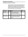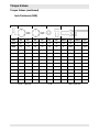
1
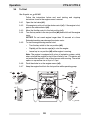
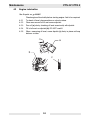
www.wackergroup.com 0163209en 0207 Pump PTS 4V PTK 4 REPAIR MANUALS 0 1 6 3 2 0 9 E N 001 PT 4 Repair Foreword This manual covers machines with Item Number: 0007683, 0007691, 0007692 Operating / Parts Information You must be familiar with the operation of this machine before you attempt to troubleshoot or repair it. Basic operating and maintenance procedures are described in the Operator’s Manual supplied with the machine. Keep a copy of the Operator’s Manual with the machine at all times. Use the separate Parts Book supplied with the machine to order replacement parts. If you are missing either of the documents, please contact Wacker Corporation to order a replacement. Damage caused by misuse or neglect of the unit should be brought to the attention of the operator to prevent similar occurrences from happening in the future. This manual provides information and procedures to safely repair and maintain the above Wacker model(s). For your own safety and protection from injury, carefully read, understand, and observe all instructions described in this manual. THE INFORMATION CONTAINED IN THIS MANUAL IS BASED ON MACHINES MANUFACTURED UP TO THE TIME OF PUBLICATION. WACKER CORPORATION RESERVES THE RIGHT TO CHANGE ANY PORTION OF THIS INFORMATION WITHOUT NOTICE. 3 Foreword WARNING PT 4 Repair CALIFORNIA Proposition 65 Warning: Engine exhaust, some of its constituents, and certain vehicle components, contain or emit chemicals known to the State of California to cause cancer and birth defects or other reproductive harm. Laws Pertaining to Spark Arresters Notice: State Health Safety Codes and Public Resources Codes specify that in certain locations spark arresters be used on internal combustion engines that use hydrocarbon fuels. A spark arrester is a device designed to prevent accidental discharge of sparks or flames from the engine exhaust. Spark arresters are qualified and rated by the United States Forest Service for this purpose. In order to comply with local laws regarding spark arresters, consult the engine distributor or the local Health and Safety Administrator. All rights, especially copying and distribution rights, are reserved. Copyright 2007 by Wacker Corporation No part of this publication may be reproduced in any form or by any means, electronic or mechanical, including photocopying, without express written permission from Wacker Corporation. Any type of reproduction or distribution not authorized by Wacker Corporation represents an infringement of valid copyrights, and violators will be prosecuted. We expressly reserve the right to make technical modifications, even without due notice, which aim at improving our machines or their safety standards. 4 PT 4 1. Safety Information 1.1 1.2 1.3 1.4 1.5 2. Operating Safety .................................................................................. 8 Operator Safety while using Internal Combustion Engines .................. 9 Service Safety .................................................................................... 10 Label Locations .................................................................................. 11 Safety Labels ...................................................................................... 12 15 Engine ................................................................................................ 15 Pump .................................................................................................. 16 Sound Measurements ........................................................................ 17 Dimensions ......................................................................................... 17 Operation 3.1 3.2 3.3 3.4 3.5 3.6 3.7 3.8 3.9 4. 7 Technical Data 2.1 2.2 2.3 2.4 3. Table of Contents 18 Application .......................................................................................... 18 Recommended Fuel ........................................................................... 18 Before Starting ................................................................................... 18 To Start ............................................................................................... 20 To Stop ............................................................................................... 21 Operation ............................................................................................ 21 Pump Wrench ..................................................................................... 21 Accessories ........................................................................................ 22 Hoses and Clamps ............................................................................. 22 Maintenance 4.1 4.2 4.3 4.4 4.5 4.6 4.7 4.8 4.9 23 Periodic Maintenance Schedule ......................................................... 23 Engine Lubrication .............................................................................. 24 Changing Oil Filter .............................................................................. 25 Air Cleaner ......................................................................................... 26 Spark Plug .......................................................................................... 27 Fuel Filter ........................................................................................... 28 Carburetor Adjustment ....................................................................... 28 Changing Mechanical Seal Coolant ................................................... 29 Adjusting Impeller Clearance ............................................................. 30 wc_br0163209en_001TOC.fm 5 Table of Contents 4.10 4.11 4.12 4.13 5. PT 4 Cleaning Pump ....................................................................................31 Storage ................................................................................................32 Lifting ...................................................................................................32 Troubleshooting ...................................................................................33 Disassembly/Assembly Procedures 5.1 5.2 5.3 5.4 5.5 5.6 5.7 5.8 5.9 34 PTS 4V Exploded View .......................................................................34 PTS 4V Components ...........................................................................35 Replacing the Flapper Valve ...............................................................36 Replacing the Impeller .........................................................................37 Replacing the Mechanical Seal ...........................................................38 Replacing the Pump Housing ..............................................................40 Volute, Insert, and Shims ....................................................................42 Replacing the Engine ..........................................................................44 Wiring Diagram ....................................................................................45 wc_br0163209en_001TOC.fm 6 PT 4 1. Safety Information Safety Information This manual contains DANGER, WARNING, CAUTION, NOTICE and NOTE callouts which must be followed to reduce the possibility of personal injury, damage to the equipment, or improper service. This is the safety alert symbol. It is used to alert you to potential personal injury hazards. Obey all safety messages that follow this symbol to avoid possible injury or death. DANGER indicates a hazardous situation which, if not avoided, will result in death or serious injury. DANGER WARNING indicates a hazardous situation which, if not avoided, could result in death or serious injury. WARNING CAUTION indicates a hazardous situation which, if not avoided, could result in minor or moderate injury. CAUTION NOTICE: Used without the safety alert symbol, NOTICE indicates a hazardous situation which, if not avoided, could result in property damage. Note: Contains additional information important to a procedure. 7 Safety Information 1.1 PT 4 Operating Safety WARNING Familiarity and proper training are required for the safe operation of machine. Machines operated improperly or by untrained personnel can be dangerous. Read the operating instructions contained in both this manual and the engine manual and familiarize yourself with the location and proper use of all controls. Inexperienced operators should receive instruction from someone familiar with the machine before being allowed to operate it. 1.1.1 NEVER allow anyone to operate this equipment without proper training. People operating this equipment must be familiar with the risks and hazards associated with it. 1.1.2 NEVER touch the engine or muffler while the engine is on or immediately after it has been turned off. These areas get hot and may cause burns. 1.1.3 NEVER use accessories or attachments that are not recommended by Wacker. Damage to equipment and injury to the user may result. 1.1.4 NEVER pump volatile, flammable or low flash point fluids. These fluids could ignite or explode. 1.1.5 NEVER pump corrosive chemicals or water containing toxic substances. These fluids could create serious health and environmental hazards. Contact local authorities for assistance. 1.1.6 NEVER open the priming plug when the pump is hot. Never loosen or remove inlet or discharge hose fittings when the pump is hot. Hot water inside could be pressurized much like the radiator on an automobile. Allow the pump to cool to the touch before loosening the plug and before loosening or removing the inlet or discharge hose fittings. 1.1.7 NEVER open pump housing cover while pump is operating, or start pump with the cover off. The rotating impeller inside the pump can cut or sever objects caught in it. 1.1.8 NEVER block or restrict flow from inlet line or discharge line. Remove kinks from discharge line before starting pump. Operation with a blocked inlet line or discharge line can cause water inside pump to overheat. 1.1.9 NEVER stand on the machine. 1.1.10 DO NOT stand under the machine while it is being hoisted or moved. 1.1.11 DO NOT attach equipment to the machine when it is suspended. 1.1.12 ALWAYS read, understand, and follow procedures in the Operator’s Manual before attempting to operate the equipment. 1.1.13 ALWAYS be sure operator is familiar with proper safety precautions and operation techniques before using machine. 8 PT 4 1.2 Safety Information 1.1.14 ALWAYS be sure the machine is on a firm, level surface and will not tip, roll, slide, or fall while operating. 1.1.15 ALWAYS close fuel valve on engines equipped with one when machine is not being operated. 1.1.16 ALWAYS store the equipment properly when it is not being used. Equipment should be stored in a clean, dry location out of the reach of children. Operator Safety while using Internal Combustion Engines DANGER Internal combustion engines present special hazards during operation and fueling. Read and follow the warning instructions in the engine owner’s manual and the safety guidelines below. Failure to follow the warnings and safety guidelines could result in severe injury or death. 1.2.1 DO NOT run the machine indoors or in an enclosed area such as a deep trench unless adequate ventilation, through such items as exhaust fans or hoses, is provided. Exhaust gas from the engine contains poisonous carbon monoxide gas; exposure to carbon monoxide can cause loss of consciousness and may lead to death. 1.2.2 DO NOT smoke while operating the machine. 1.2.3 DO NOT smoke when refueling the engine. 1.2.4 DO NOT refuel a hot or running engine. 1.2.5 DO NOT refuel the engine near an open flame. 1.2.6 DO NOT spill fuel when refueling the engine. 1.2.7 DO NOT run the engine near open flames. 1.2.8 ALWAYS refill the fuel tank in a well-ventilated area. 1.2.9 ALWAYS replace the fuel tank cap after refueling. 9 Safety Information 1.3 PT 4 Service Safety WARNING Poorly maintained machines can become a safety hazard! In order for the machine to operate safely and properly over a long period of time, periodic maintenance and occasional repairs are necessary. 1.3.1 DO NOT attempt to clean or service the machine while it is running. Rotating parts can cause severe injury. 1.3.2 DO NOT crank a flooded engine with the spark plug removed on gasoline-powered engines. Fuel trapped in the cylinder will squirt out the spark plug opening. 1.3.3 DO NOT test for spark on gasoline-powered engines if the engine is flooded or the smell of gasoline is present. A stray spark could ignite the fumes. 1.3.4 DO NOT use gasoline or other types of fuels or flammable solvents to clean parts, especially in enclosed areas. Fumes from fuels and solvents can become explosive. 1.3.5 ALWAYS operate machine with all safety devices and guards in place and in working order. DO NOT modify or defeat safety devices. DO NOT operate machine if any safety devices or guards are missing or inoperative. 1.3.6 ALWAYS keep the area around the muffler free of debris such as leaves, paper, cartons, etc. A hot muffler could ignite the debris and start a fire. 1.3.7 ALWAYS replace worn or damaged components with spare parts designed and recommended by Wacker Corporation. 1.3.8 ALWAYS disconnect the spark plug on machines equipped with gasoline engines, before servicing, to avoid accidental start-up. 1.3.9 ALWAYS keep the machine clean and labels legible. Replace all missing and hard-to-read labels. Labels provide important operating instructions and warn of dangers and hazards. 1.3.10 ALWAYS handle impeller carefully. The impeller can develop sharp edges which can cut. 10 PT 4 1.4 Safety Information Label Locations CAUTION VORSICHT PRECAUCION PRECAUTION wc_gr001479 11 Safety Information 1.5 PT 4 Safety Labels Wacker machines use international pictorial labels where needed. These labels are described below: Label Meaning DANGER! Engines emit carbon monoxide; operate only in well-ventilated area. Read the Operator’s Manual. No sparks, flames, or burning objects near the machine. Shut off the engine before refueling. WARNING! Hot surface! CAUTION! Read and understand the supplied Operator’s Manuals before operating this machine. Failure to do so increases the risk of injury to yourself or others. WARNING! Do not open if pump is hot. Hot water and/or steam inside could be pressurized. WARNING! Never pump volatile, flammable or low flash point fluids. These fluids could ignite or explode. CAUTION CAUTION! Lifting point. VORSICHT PRECAUCION PRECAUTION 12 PT 4 Safety Information Label Meaning Guaranteed sound power level in dB(A). Key switch: off on start Throttle control lever: Rabbit = Full or Fast Turtle = Idle or Slow M E N O M O N E E F A L L S , W I U S A 5 3 0 5 1 M o d e l N u m b e r R e v . lb s k g M A D E IN U S A d B (A ) S e r ia l N u m b e r k W h p M a n u f. Y r. 8 8 2 2 3 Ite m A nameplate listing the model number, item number, revision number, and serial number is attached to each unit. Please record the information found on this plate so it will be available should the nameplate become lost or damaged. When ordering parts or requesting service information, you will always be asked to specify the model number, item number, revision number, and serial number of the unit. This machine may be covered by one or more patents. 13 Safety Information PT 4 Notes 14 PTS 4V / PTK 4 2. Technical Data Technical Data 2.1 Engine Item No. PTS 4V PTS 4V 0007683 Rev. 115 & lower 0007691 Rev. 116 & lower 0007683 Rev. 116 & higher 0007691 Rev. 117 & higher Engine Engine Make Briggs and Stratton Engine Model Rated Power Vanguard 3034471256-E2 Vanguard 305447-0144E1 12 (16) kW (Hp) Spark Plug Champion RC12YC Electrode Gap mm (in.) Engine Speed rpm 3600 Air Cleaner type Dual element Battery Engine Lubrication Fuel Fuel Tank Capacity 12 / 230 / 32 / 22NF V/CCA/ amp-hr./size oil grade / service class Engine Oil Capacity 0.76 (0.030) >5°C (40°F) SAE 10W30 / SG, SF, or SE <5°C (40°F) SAE 30W / SG, SF, or SE 1400 (48) ml (oz.) Regular unleaded gasoline type 17 (4.5) l (gal.) 15 Technical Data 2.2 PTS 4V / PTK 4 Pump Item number: PTS 4V, PTK 4 0007683, 0007691, 0007692 Pump Weight 163 (360) kg (lbs.) *Max. Suction Lift m (ft.) 7.5 (25) Max. Total Head m (ft.) 32 (106) Mechanical Seal Lubrication oil grade ml (oz.) SAE 30 150 (5) Suction / Discharge Diameter mm (in.) 100 (4) Max. Solid Size mm (in.) 50 (2) *Based on pump operating at sea level. Maximum suction lift will be less at higher altitudes. 16 PTS 4V / PTK 4 2.3 Technical Data Sound Measurements The required sound specifications per Appendix 1, Paragraph 1.7.4 of the EC-Machine Regulations, is: • the guaranteed sound power level (LWA) = 104 dB(A) These sound values were determined according to ISO 3744 for the sound power (LWA). The sound measurements were obtained with the unit operating on pavement at nominal speed. 2.4 Dimensions mm (in.) 915 (36) 890 (35) 890 (35) wc_gr001478 17 Operation 3. PTS 4V / PTK 4 Operation 3.1 Application This pump is intended for removing clean water and water containing some debris and solids. Refer to “Technical Data” for maximum solid size. 3.1.1 NEVER pump volatile, flammable or low flash point fluids. These fluids could ignite or explode. WARNING 3.1.2 WARNING 3.2 NEVER pump corrosive chemicals or water containing toxic substances. These fluids could create serious health and environmental hazards. Contact local authorities for assistance. Recommended Fuel The engine requires regular grade unleaded gasoline. Use only fresh, clean gasoline. Gasoline containing water or dirt will damage fuel system. Consult engine Owner’s Manual for complete fuel specifications. 3.3 Before Starting See Graphic: wc_gr000013 3.3.1 Read safety instructions at the beginning of manual. 3.3.2 Place pump as near to water as possible, on a firm, flat, level surface. 3.3.3 To prime pump, remove prime plug (a) and fill pump case with water. If the pump case is not filled with water before starting, it will not begin pumping. DO NOT open priming plug, discharge plug, or loosen hose fittings if pump is hot! Water or vapor inside pump may be under pressure. WARNING 3.3.4 Check for leaks between pump and engine. If water is leaking, the seal inside pump is worn or damaged. Continued operation may cause water damage to engine. 18 PTS 4V / PTK 4 Operation 3.3.5 Check that hoses are securely attached to pump. Suction hose (b) must not have any air leaks. Tighten hose clamps (c) and couplings (d). Check that discharge hose (e) is not restricted. Lay hose out as straight as possible. Remove any twists or sharp bends from hose which may block the flow of water. 3.3.6 Make sure suction strainer (f) is clean and securely attached to end of hose. The strainer is designed to protect the pump by preventing large objects from being pulled into the pump. NOTICE: Strainer should be positioned so it will remain completely under water. Running the pump with the strainer above water for long periods can damage the pump. 3.3.7 Check fuel level, engine oil level, and condition of air cleaner. 19 Operation 3.4 PTS 4V / PTK 4 To Start See Graphic: wc_gr001480 Follow the instructions below and read starting and stopping instuctions found in the engine owner’s manual. 3.4.1 Open the fuel valve (b1). 3.4.2 If the engine is cold, pull out the choke control (a1). If the engine is hot, push in the choke control (a2). 3.4.3 Move the throttle control to the fast position (c1). 3.4.4 Turn the key switch to the start position (d3) and hold it until the engine starts. NOTICE: Do not crank engine longer than 15 seconds at a time. Extended cranking can damage the starter motor. 3.4.5 To start the engine using manual start: • Turn the key switch to the run position (d2). • Rapidly pull the starter rope (e) to start the engine. • Leave key in run position (d2) while engine is running. Note: The engine is equipped with a low oil protection system, which does not allow the engine to start if the oil level is low. This device will not protect the engine if a low oil level occurs while running. The switch opens on a pressure rise of 4 psi ±1.5 psi. a1 3.4.6 Push the choke in as the engine warms (a2). 3.4.7 Keep the engine throttle in the fast position while operating pump. a2 b2 b1 d1 d2 c1 d3 c2 wc_gr001480 20 PTS 4V / PTK 4 3.5 Operation To Stop See Graphic: wc_gr001480 3.6 3.5.1 Reduce engine RPM by moving the throttle completely to the idle position (c2). 3.5.2 Turn the engine switch to the stop position (d1). 3.5.3 Close the fuel valve (b2). Operation Pump should begin pumping water within a minute depending on length of suction hose and height of pump above water. Longer hoses will require more time. If pump does not prime, check for loose fittings or air leak in suction hose. Make sure strainer in water is not blocked. Run engine at full speed while operating pump. 3.6.1 WARNING 3.7 NEVER pump corrosive chemicals or water containing toxic substances. These fluids could create serious health and environmental hazards. Contact local authorities for assistance. Pump Wrench See Graphic: wc_gr001481 The wrench (a) supplied with the pump can be used to loosen and tighten: hose couplings, knobs on pump cover, priming plug, and drain plug on front cover. Store wrench on pump frame. a wc_gr001481 21 Operation 3.8 PTS 4V / PTK 4 Accessories Wacker offers a complete line of fittings, hoses, and clamps to properly connect the pump to match various job conditions. 3.9 Hoses and Clamps See Graphic: wc_gr000021 Suction hoses (a) must be rigid enough not to collapse when pump is operating. Discharge hoses (b) are usually thin-walled collapsible hoses. Rigid hoses similar to those used as suction hoses may also be used as discharge hoses. Note: Suction and discharge hoses are available from Wacker. Contact your nearest dealer for more information. Two clamps (c) are recommended for connection of suction hoses to inlet coupling. Note: This connection is important. Even a small air leak on the suction side of pump will prevent the pump from priming. For other hose connections, one T-bolt or worm-gear type clamp is usually sufficient to hold hoses in place. In some cases, slight variances in hose diameters may make it necessary to add more clamps in order to maintain tight connections. 22 PTS 4V / PTK 4 4. Maintenance Maintenance 4.1 Periodic Maintenance Schedule The chart below lists basic machine and engine maintenance. Refer to the engine manufacturer’s Operator’s Manual for additional information on engine maintenance. Daily before starting Check fuel level. Check engine oil level. Inspect for leaks between pump and engine. Inspect air filter. Clean as needed. Check external hardware. After first 5 hrs. Every 50 hrs. Inspect shock mounts for damage. Change oil in pump housing. Change engine oil and replace filter. Every 100 hrs. Every year Replace air cleaner. Check and clean spark plug. Replace in-line fuel filter. Check and adjust valve clearances. 23 Maintenance 4.2 PTS 4V / PTK 4 Engine Lubrication See Graphic: wc_gr000562 Check engine oil level daily before starting engine. Add oil as required. 4.2.1 To check oil level, place machine on a level surface. 4.2.2 Clean area around oil fill and remove dipstick. 4.2.3 Pour oil (a) slowly, checking oil level occasionally with dipstick. 4.2.4 Fill to full mark on dipstick (b). DO NOT overfill. 4.2.5 When measuring oil level, screw dipstick (c) firmly in place until cap bottoms on tube. a b c 24 PTS 4V / PTK 4 4.3 Maintenance Changing Oil Filter See Graphic: wc_gr001482 Replace the oil filter after every 100 hours of operation. 4.3.1 Drain the engine oil and replace it with fresh oil before removing the used oil filter. See Technical Data for oil quantity and type. Note: In the interests of environmental protection, place a plastic sheet and a container under the machine to collect any liquid which drains off. Dispose of this liquid in accordance with environmental protection legislation. 4.3.2 Remove the used filter before installing a new filter, lightly oil the filter gasket with fresh, clean engine oil. 4.3.3 Screw the filter (a) on by hand until the gasket makes contact, then tighten an additional 1/2 to 3/4 turn. 4.3.4 Start and run the engine to check for leaks. Stop the engine. Recheck the oil level and add oil if required. See Engine Lubrication. a wc_gr001482 25 Maintenance 4.4 PTS 4V / PTK 4 Air Cleaner See Graphic: wc_gr000564 Service air cleaner frequently to prevent carburetor malfunction. NOTICE: NEVER run the engine without the air cleaner. Severe engine damage will occur. NEVER use gasoline or other types of low flash point solvents for cleaning the air cleaner. A fire or explosion could result. The engine is equipped with a dual element air cleaner. To service air cleaner: 4.4.1 Remove cover (a), knob (b), and retaining plate (c). 4.4.2 Remove foam precleaner (d) from filter cartridge (e). 4.4.3 Wash precleaner in liquid detergent and water. Squeeze dry in a clean cloth. Saturate precleaner in engine oil, squeeze out excess oil. Replace precleaner if it is damaged or heavily soiled. 4.4.4 To clean cartridge, remove and tap lightly on a flat surface. Replace cartridge if it is damaged or heavily soiled. Note: Do not use petroleum solvents to clean precleaner or cartridge. Petroleum type solvents will damage them. Do not use pressurized air to clean cartridge. Pressurized air can also damage the cartridge. a b c d e 26 PTS 4V / PTK 4 4.5 Maintenance Spark Plug See Graphic: wc_gr000028 Clean or replace the spark plug as needed to ensure proper operation. Refer to the engine owner’s manual. The muffler becomes very hot during operation and remains hot for a while after stopping the engine. Do not touch the muffler while it is hot. WARNING Note: Refer to the Technical Data for the recommended spark plug type and the electrode gap setting. 4.5.1 Remove the spark plug and inspect it. 4.5.2 Replace the spark plug if the insulator is cracked or chipped. 4.5.3 Clean the spark plug electrodes with a wire brush. 4.5.4 Set the electrode gap (a). 4.5.5 Tighten the spark plug securely. NOTICE: A loose spark plug can become very hot and may cause engine damage. 27 Maintenance 4.6 PTS 4V / PTK 4 Fuel Filter See Graphic: wc_gr001483 4.6.1 Change in-line fuel filter (a) once a year. 4.6.2 Check fuel lines and fittings frequently for cracks or leaks. Replace as needed. Allow engine to cool and close fuel valve before replacing fuel filter. a a b wc_gr001483 4.7 Carburetor Adjustment See Graphic: wc_gr000566 Note: The air cleaner must be in place and the engine warm when making adjustments to carburetor. 4.7.1 With engine running, place throttle in SLOW position and rotate carburetor throttle lever against the idle speed screw (a) and hold it there. 4.7.2 Turn the idle speed screw to obtain 1300 to 1500 rpm. 4.7.3 While still holding the throttle lever against the idle speed screw, turn the idle mixture valve (b) midway between limits. 4.7.4 Readjust the idle speed to 1200 rpm and release carburetor throttle lever. Engine should accelerate smoothly when throttle is opened. If it does not, readjust idle mixture valve slightly counterclockwise. 28 PTS 4V / PTK 4 4.8 Maintenance Changing Mechanical Seal Coolant See Graphic: wc_gr001484 Change seal coolant every 50 hours using SAE 30W oil. 4.8.1 Remove plugs (a) from both sides of pump housing for venting. 4.8.2 Remove bottom plug (b) and allow oil to drain from oil cavity. 4.8.3 Install bottom drain plug. 4.8.4 Fill oil cavity through one of the side plug (a) holes until oil is level with top of hole or flows out hole on opposite side. Oil quantity - approximately 150 ml (5 ounces). 4.8.5 Install all plugs before operating pump. a b wc_gr001484 29 Maintenance 4.9 PTS 4V / PTK 4 Adjusting Impeller Clearance See Graphic: wc_gr001485 If it is necessary to replace impeller or volute insert, be sure clearance between impeller and insert is adjusted correctly. The impeller (e) should be as close to the insert (a) as possible without rubbing against it. Clearance is adjusted by adding or removing shims (b) from behind insert. Inserts are attached to the pump cover and must be unbolted (c) before they can be removed. Check clearance (d) between impeller and insert by slowly pulling starter rope to turn impeller. Note: Remove spark plug to make it easier to turn impeller. On diesel engines open decompression device before cranking engine. If starter or crank is difficult to turn, or rubbing is heard from inside pump, the impeller and insert are too close to each other. Remove a shim from behind insert and check again for rubbing. Continue removing shims until impeller turns easily. Note: It is important not to remove too many shims or the clearance between the impeller and insert will become too wide and pump performance will be reduced. As the impeller wears down, additional shims may be required to maintain the clearance between the impeller and insert. c b d e a 30 wc_gr001485 PTS 4V / PTK 4 Maintenance 4.10 Cleaning Pump See Graphic: wc_gr001486 After pumping water containing a large amount of dirt or debris, clean out inside of pump housing. 4.10.1 Remove drain plug (a) from pump housing and drain any water left in pump. 4.10.2 Loosen the four knobs (b) holding the pump cover and remove cover. 4.10.3 Clean out dirt and debris. Inspect impeller and volute insert for wear. Note: Tighten cover evenly at all four corners using a wrench. The impeller may develop sharp edges. Use care when cleaning around impeller to prevent getting cut. CAUTION a b wc_gr001486 31 Maintenance PTS 4V / PTK 4 4.11 Storage If pump is being stored for more than 30 days: NEVER open priming plug, discharge plug, or cover when pump is hot. WARNING 4.11.1 Remove discharge plug from pump casing and drain out any water left in the housing after pump has cooled. 4.11.2 Remove pump cover and clean inside of pump housing. Coat inside of pump with a light film of oil to reduce corrosion. A spray can of oil works well for this. 4.11.3 Tape up suction and discharge ports to prevent anything from falling into pump. 4.11.4 Change engine oil and follow procedures described in engine manual for engine storage. 4.11.5 Cover pump and engine and store in a clean, dry area. 4.12 Lifting See Graphic: wc_gr001487 To lift machine mechanically: Before attempting to lift, be sure that lifting devices can safely handle weight of machine. See Technical Data for weight of machine. CAUTION Attach hook, harness, or cable to machine as shown and lift as desired. wc_gr001487 32 PTS 4V / PTK 4 Maintenance 4.13 Troubleshooting Problem / Symptom Reason / Remedy Pump does not take in water. • Not enough priming water in housing. • Engine speed too low. Adjust speed. • Strainer plugged. Clean strainer. • Suction hose damaged. Replace or repair hose. • Air leak at suction port. Check that fittings are tight and sealing properly. • Pump too high above water. • Debris collecting in pump housing. Clean pump housing. • Too much clearance between impeller and insert. Pump takes in water, little or no discharge. • Engine speed too low. Adjust speed. • Suction strainer partially plugged. Clean strainer. • Impeller worn. Adjust clearance by adding shims or replace impeller. • Volute insert worn or damaged. Adjust clearance or replace insert. Suction hose leaks at inlet. • Clamps are not sealing properly. Tighten, replace, or add clamp. • Hose diameter is too large. • Hose is damaged. Discharge hose does not stay on coupling. • Pressure may be too high for clamps being used. Add another clamp. • Hose kinked or end blocked. Check hose. Impeller does not turn; pump • Impeller jammed or blocked. Open pump cover and is hard to start. clean dirt and debris from inside of pump housing. • Impeller and insert binding. Adjust clearance by removing shim from behind insert. Engine does not start or stops during operation. • Debris in pump housing, blocking impeller. • Low oil level in engine. • Impeller rubbing on insert. 33 Disassembly/Assembly Procedures 5. PT 4 Repair Disassembly/Assembly Procedures 5.1 PTS 4V Exploded View 1 3 4 2 13 14 32 15 5 16 7 17 6 18 19 9 8 10 12 11 24 26 25 22 23 28 20 21 27 2 29 30 31 4 3 34 wc_gr003536 PT 4 Repair 5.2 Disassembly/Assembly Procedures PTS 4V Components Ref. Description Qty. Ref. Description Qty. 1 Kit-pump housing (incl. 2–4) 1 19 Impeller 1 2 Fitting-nipple 2 20 Kit-suction port replacement (incl. 2) 1 3 Plug-priming 2 21 Locknut M8 4 4 Gasket-priming plug 2 22 Gasket-flapper 1 5 Seal-shaft 1 23 Stud M8x30 4 6 Plug M10, hex 3 24 Kit-pump cover (incl. 3 & 4) 1 7 Seal-ring 3 25 Volute 1 8 Screw M12x40 4 26 Shim .005"" A/R 9 Bolt-eye 4 Shim .010"" A/R 10 Stud M8x20 2 Shim .020"" A/R 11 Nut M8 2 Shim .040"" A/R 12 Setscrew M8x10 3 27 Kit-volute insert (incl. 28) 1 13 Screw 7/16-14x1-1/4 4 28 Screw M8x35 3 14 Gasket-pump oil cover 1 29 O-Ring 1 15 Cover-oil chamber 1 30 O-Ring 1 16 Screw M8x20 5 31 Knob 4 17 O-Ring 1 32 Sleeve-shaft 1 18 Seal-mechanical (std.) 1 - --- A/R = as required 35 Disassembly/Assembly Procedures 5.3 PT 4 Repair Replacing the Flapper Valve See Graphic: wc_gr003537 The flapper valve (1) is located at the pump inlet (2). During operation, this valve is open allowing a free path for water to flow into the pump case. When the pump is stopped, it closes and prevents water in the suction line from being lost. A leak around the flapper gasket will cause the suction line to lose its prime and make the pump difficult or impossible to operate. Removal: 5.3.1 Shut down the machine and remove the inlet hose if it is connected. 5.3.2 Remove the locknuts (3) that secure the suction (inlet) port (2) to the pump. 5.3.3 Remove the inlet port and the flapper valve assembly (1). Installation: 5.3.4 Install the new flapper valve assembly with the large washer (4) facing the inside of the cover and the flap opening facing down. This washer acts as a counterweight and helps seal the flapper gasket against the pump inlet when the pump stops. 5.3.5 Mount the inlet port (2) to the pump. Tighten the lock nuts (3) evenly until the flapper gasket begins to compress. NOTICE: DO NOT overtighten the lock nuts. Overtightening may distort the flapper gasket causing an air leak at the inlet port. 1 2 4 3 2 3 4 wc_gr003537 36 PT 4 Repair 5.4 Disassembly/Assembly Procedures Replacing the Impeller See Graphic: wc_gr003540 Removal: CAUTION Impeller edges can be extremely sharp; use care when removing them. 5.4.1 Loosen the knobs (a) securing the housing cover/volute assembly (b) to the pump housing and remove the housing cover/volute assembly. 5.4.2 Using an impact wrench, loosen the impeller (c) by turning the nut (molded into impeller casting) counterclockwise. Once loose, pull the impeller from the volute. Installation: 5.4.3 Apply anti-seize to the engine shaft and screw the impeller (c) onto the engine shaft. 5.4.4 Reinstall the housing cover/volute assembly (b) to the housing and tighten with knobs (a). c a b wc_gr003540 37 Disassembly/Assembly Procedures 5.5 PT 4 Repair Replacing the Mechanical Seal See Graphic: wc_gr003541 Removal: 5.5.1 Remove the impeller. See section Replacing the Impeller. 5.5.2 Pull the front half (a) of the mechanical seal off of the back of the impeller. 5.5.3 Remove the drain plug (b) from the bottom of the pump housing and drain the oil from the pump. 5.5.4 Remove the cap screws (c) and the nuts (d) from the studs. Pull the oil housing (e) from the pump housing. Note: If the oil housing is difficult to remove, remove the set screws (f) and in their place insert pusher screws. Use the pusher screws to remove the oil housing. 5.5.5 Press the back half (ceramic portion) (g) of the mechanical seal from the oil housing. 5.5.6 Inspect the large O-ring (h) of the oil housing and replace it if is worn or damaged. Installation: Note: Always replace both halves of the mechanical seal as a set. Clean the mating surfaces of the mechanical seal with alcohol before installing it. Note: If the carbon face (i) has worn flush with the surface of the seal, replace the mechanical seal to prevent the pump from leaking. 5.5.7 Press the ceramic portion (g) of the mechanical seal into the oil housing (e). 5.5.8 Secure the oil housing to the pump housing with the cap screws (c) and nuts (d). Use anti-seize on the cap screws and torque them to 22 Nm (16 ft.lbs.). Also torque the nuts to 22 Nm (16 ft.lbs.). 5.5.9 Install the drain plug (b) into the bottom of the pump housing. Remove the filler plug (j) and fill the pump with oil. Reinstall the filler plug. 5.5.10 Install the front half (a) of the mechanical seal onto the back of the impeller. 5.5.11 Reinstall the volute and the front cover. 38 PT 4 Repair Disassembly/Assembly Procedures a b j c f d e g i h wc_gr003541 39 Disassembly/Assembly Procedures 5.6 PT 4 Repair Replacing the Pump Housing See Graphic: wc_gr003543 Removal: 5.6.1 Remove the impeller and the oil housing. See sections Replacing the Impeller and Replacing the Mechanical Seal. 5.6.2 Remove the lock nuts that secure the shockmounts (a) to the frame. 5.6.3 Loosen the lock nuts (b) that secure the engine to the frame. The engine will need to be tipped up in order to pull the pump housing, with the shockmounts attached, free from the machine. 5.6.4 Remove the screws that secure the oil filter bracket (c) to the frame. 5.6.5 Remove the screw that secures the cable clamp (d) to the pump housing. 5.6.6 Remove the gasket (e). 5.6.7 Remove the cap screws (f) that secure the pump housing to the engine. Heat the screws if necessary to beak down the thread locking compound. Once the screws have been removed, pull the pump housing from the engine. Tip the engine as necessary to allow the pump housing (g) to be pulled free of the frame. 5.6.8 Press the seal (h) from the pump housing. Installation: 5.6.9 Press the seal (h) into the pump housing. Lightly coat the rubber portion of the seal with oil. 5.6.10 Tip the engine up and slide the pump housing into position over the engine drive shaft and onto the frame. 5.6.11 Secure the pump housing (g) to the engine with the cap screws. Use Loctite 271 or an equivalent on the cap screws and torque them to 54 Nm (39 ft.lbs.). 5.6.12 Secure the engine to the frame with the screws and the lock nuts (b). 5.6.13 Secure the shock mounts (a) to the frame with the lock nuts. 5.6.14 Reinstall the cable clamp (d). 5.6.15 Secure the oil filter bracket (c) to the frame. 5.6.16 Install the gasket (e). 5.6.17 Reinstall the oil housing and the impeller. See sections Replacing the Mechanical Seal and Replacing the Impeller. 40 PT 4 Repair Disassembly/Assembly Procedures f b e g h a d c e f h g wc_gr003543 41 Disassembly/Assembly Procedures 5.7 PT 4 Repair Volute, Insert, and Shims See Graphic: wc_gr003544 Disassembly: 5.7.1 Remove the housing cover/volute assembly (a) from the pump. 5.7.2 Remove the three screws (b) that secure the volute assembly (c) to the housing cover and remove the volute assembly. 5.7.3 Remove the insert (d) from inside of the volute. 5.7.4 Remove the shims (e) from inside of the volute. 5.7.5 Check the O-rings (f, g) on the back side of the housing cover. Replace the O-rings if they are worn or damaged. Assembly: 5.7.6 Place the same number of shims (e) into the volute as were removed. 5.7.7 Place the insert (d) into the volute. 5.7.8 Secure the volute assembly (c) to the housing cover with the three screws (b). 5.7.9 Install the housing cover/volute assembly (a) onto the pump. 5.7.10 Check the shimming of the insert. The pump will perform best when the impeller is as close to the insert as possible without rubbing against it. To check the shimming: • Place the keyswitch in the OFF position. • Slowly pull the starter rope to check that the drive shaft will spin. • Add shims as necessary until the drive shaft binds, then remove the thinnest shim. • Pull the starter rope again to check that the drive shaft will spin. If it does, the shimming is correct. 42 PT 4 Repair Disassembly/Assembly Procedures d e f b c g a d b e f g wc_gr003544 43 Disassembly/Assembly Procedures 5.8 PT 4 Repair Replacing the Engine See Graphic: wc_gr003542 Removal: 5.8.1 Remove the pump housing. See section Replacing the Pump Housing. 5.8.2 Disconnect the fuel hose (a). 5.8.3 Disconnect the wiring (b) to the battery. 5.8.4 Remove the screws and lock nuts that secure the engine to the frame (if not already removed) and pull the engine from the frame. Installation: 5.8.5 Position the engine into the frame. 5.8.6 Connect the wiring (b) to the battery. 5.8.7 Connect the fuel hose (a). 5.8.8 Reinstall the pump housing. See section Replacing the Pump Housing. a b wc_gr003542 44 PT 4 Repair 5.9 Disassembly/Assembly Procedures Wiring Diagram 7 R Y + R – R B 1 6 Or W Br 5 G L B M S Y 2 B Or 4 Y B B R Ref. Description Ref. 3 wc_gr003594 Description 1 Battery 5 Key switch 2 Voltage regulator 6 Starter motor 3 To engine 7 Starter solenoid 4 Low oil shutdown switch - --- Wire Colors B Black R Red Y Yellow Or Orange G Green T Tan Br Brown Pr Purple L Blue V Violet Cl Clear Sh Shield P Pink W White Gr Gray LL Light blue 45 Disassembly/Assembly Procedures Notes 46 PT 4 Repair Threadlockers and Sealants Threadlockers and Sealants Threadlocking adhesives and sealants are specified throughout this manual by a notation of “S” plus a number (S#) and should be used where indicated. Threadlocking compounds normally break down at temperatures above 175°C (350°F). If a screw or bolt is hard to remove, heat it using a small propane torch to break down the sealant. When applying sealants, follow instructions on container. The sealants listed are recommended for use on Wacker equipment. TYPE ( ) = Europe Loctite 222 Hernon 420 Omnifit 1150 (50M) COLOR USAGE Purple Low strength, for locking threads smaller than 6 mm (1/4”). Hand tool removable. Temp. range: -54 to 149°C (-65 to 300°F) Blue Medium strength, for locking threads Loctite 243 Hernon 423 larger than 6 mm (1/4”). Omnifit 1350 (100M) Hand tool removable. Temp. range: -54 to 149°C (-65 to 300°F) Loctite 271/277 Red High strength, for all threads up to 25 mm Hernon 427 (1”). Omnifit 1550 (220M) Heat parts before disassembly. Temp. range: -54 to 149°C (-65 to 300°F) Loctite 290 Green Medium to high strength, for locking Hernon 431 preassembled threads and for sealing Omnifit 1710 (230LL) weld porosity (wicking). Gaps up to 0.13 mm (0.005”) Temp. range: -54 to 149°C (-65 to 300°F) Loctite 609 Green Medium strength retaining compound for Hernon 822 slip or press fit of shafts, bearings, gears, Omnifit 1730 (230L) pulleys, etc. Gaps up to 0.13 mm (0.005”) Temp. range: -54 to 149°C (-65 to 300°F) Loctite 545 Brown Hydraulic sealant Hernon 947 Temp. range: -54 to 149°C (-65 to 300°F) Omnifit 1150 (50M) Loctite 592 White Pipe sealant with Teflon for moderate Hernon 920 pressures. Omnifit 790 Temp. range: -54 to 149°C (-65 to 300°F) Loctite 515 Purple Form-in-place gasket for flexible joints. Hernon 910 Fills gaps up to 1.3 mm (0.05”) Omnifit 10 Temp. range: -54 to 149°C (-65 to 300°F) PART NO. – SIZE 73287 - 10 ml 29311 - .5 ml 17380 - 50 ml 29312 - .5 ml 26685 - 10 ml 73285 - 50 ml 28824 - .5 ml 25316 - 10 ml 29314 - .5 ml 79356 - 50 ml 26695 - 6 ml 73289 - 50 ml 70735 - 50 ml Threadlockers and Sealants Threadlockers and Sealants (continued) Threadlocking adhesives and sealants are specified throughout this manual by a notation of “S” plus a number (S#) and should be used where indicated. Threadlocking compounds normally break down at temperatures above 175°C (350°F). If a screw or bolt is hard to remove, heat it using a small propane torch to break down the sealant. When applying sealants, follow instructions on container. The sealants listed are recommended for use on Wacker equipment. TYPE ( ) = Europe COLOR USAGE Loctite 496 Clear Instant adhesive for bonding rubber, metal Hernon 110 and plastics; general purpose. Omnifit Sicomet 7000 For gaps up to 0.15 mm (0.006”) Read caution instructions before using. Temp. range: -54 to 82°C (-65 to 180°F) Loctite Primer T Aerosol Fast curing primer for threadlocking, Hernon Primer 10 Spray retaining and sealing compounds. Must Omnifit VC Activator be used with stainless steel hardware. Recommended for use with gasket sealants. PART NO. – SIZE 52676 - 1oz. 2006124-6 oz. Torque Values Torque Values Metric Fasteners (DIN) TORQUE VALUES (Based on Bolt Size and Hardness) 8.8 10.9 WRENCH SIZE 12.9 Size Nm ft.lb. Nm ft.lb. Nm ft.lb. Metric Inch Metric Inch M3 1.2 *11 1.6 *14 2.1 *19 5.5 7/32 2.5 – M4 2.9 *26 4.1 *36 4.9 *43 7 9/32 3 – M5 6.0 *53 8.5 6 10 7 8 5/16 4 – M6 10 7 14 10 17 13 10 – 5 – M8 25 18 35 26 41 30 13 1/2 6 – M10 49 36 69 51 83 61 17 11/16 8 – M12 86 63 120 88 145 107 19 3/4 10 – M14 135 99 190 140 230 169 22 7/8 12 – M16 210 155 295 217 355 262 24 15/16 14 – M18 290 214 405 298 485 357 27 1-1/16 14 – M20 410 302 580 427 690 508 30 1-1/4 17 – 1 ft.lb. = 1.357 Nm * = in.lb. 1 inch = 25.4 mm Torque Values Torque Values (continued) Inch Fasteners (SAE) Size Nm ft.lb. Nm ft.lb. Nm ft.lb. Metric Inch Metric Inch No.4 0.7 *6 1.0 *14 1.4 *12 5.5 1/4 – 3/32 No.6 1.4 *12 1.9 *17 2.4 *21 8 5/16 – 7/64 No.8 2.5 *22 3.5 *31 4.7 *42 9 11/32 – 9/64 No.10 3.6 *32 5.1 *45 6.8 *60 – 3/8 – 5/32 1/4 8.1 6 12 9 16 12 – 7/16 – 3/32 5/16 18 13 26 19 33 24 13 1/2 – 1/4 3/8 31 23 45 33 58 43 – 9/16 – 5/16 7/16 50 37 71 52 94 69 16 5/8 – 3/8 1/2 77 57 109 80 142 105 19 3/4 – 3/8 9/16 111 82 156 115 214 158 – 13/16 – – 5/8 152 112 216 159 265 195 24 15/16 – 1/2 3/4 271 200 383 282 479 353 – 1-1/8 – 5/8 1 ft.lb. = 1.357 Nm * = in.lb. 1 inch = 25.4 mm Wacker Construction Equipment AG · Preußenstraße 41 · D-80809 München · Tel.: +49-(0)89-3 54 02 - 0 · Fax: +49 - (0)89-3 54 02-3 90 Wacker Corporation · P.O. Box 9007 · Menomonee Falls, WI 53052-9007 · Tel. : (262) 255-0500 · Fax: (262) 255-0550 · Tel. : (800) 770-0957 Wacker Asia Pacific Operations · Skyline Tower, Suite 2303, 23/F · 39 Wang Kwong Road, Kowloon Bay, Hong Kong · Tel. +852 2406 60 32 · Fax: +852 2406 60 21