1
Blower System Installation Guide
Layout Considerations for a Reliable, Energy Efficient, and Safe Blower System
By Kaeser’s Blower and
Engineering Experts
Introduction
About the Authors
Receiving
Equipment
This e-book was written for you by Kaeser’s blower system experts.
Location
At Kaeser, we believe the more you know about operating blower
systems, the more you’ll get out of them. That’s why we’re committed to offering you the most current information you need to
wisely install, operate, and maintain yours.
Ventilation
Our goal is to help you install the most successful blower system
possible. The tips, guidelines, and warnings included in this ebook are meant to do just that.
Electrical
Supply
While the information included in this e-book is comprehensive,
we recognize that each system and application is unique. Applying the principles you read here is an excellent place to start.
For the best in system optimization that is tailored to your needs,
contact us for additional support.
Throughout the e-book, there are boxes with efficiency tips and
additional resources. The links included in those will take you
directly to more information that our engineers and blower system experts have selected specifically to further assist with your
blower system.
Piping
Package
Integration
“
”
Tip:
ButtonTip:
Basic Text
Look for these boxes throughout
the e-book for additional tips.
www.us.kaeser.com Copyright © 2015 Kaeser Compressors, Inc. All Rights Reserved.
Building an
Efficient
System
Our goal is to help you install the most successful blower system possible. The tips, guidelines,
and warnings included in this e-book are meant
to do just that.
Preventive
Maintenance
Safety
Advisories
More Resources:
Button
Basic Text.
More
Resources:
Additional
Resources
Linksresources
are underlined.
Additional
are in these
boxes. Want to hear the latest
Kaeser news?
Visit www.kaeser.com/connect
2
Appendices
Table of Contents
Introduction
Section I: Receiving Equipment
Section II: Location
Section III: Ventilation
Section IV: Electrical Safety
Section V: Piping
Section VI: Package Integration
Section VII: Building an Efficient System
Section VIII: Preventive Maintenance
Section IX: Safety Advisories
Section X: Additional Resources
Appendices
www.us.kaeser.com Copyright © 2015 Kaeser Compressors, Inc. All Rights Reserved.
3
Introduction
Introduction
Receiving
Equipment
Blowers are vital pieces of equipment in a variety of different
applications. Many plants face shut down when there is any kind
of problem or issue with their blower system, that’s why proper
planning is essential before installing a new system. If you are
upgrading an existing system, you may be faced with physical restrictions requiring creative solutions. Whether installing a
brand new system or upgrading an existing one, the information
contained in this e-book will assist you in identifying the best
configuration and in getting the best possible performance from
your blower system.
Location
Ventilation
For the purposes of this e-book, it’s assumed you have already
identified pressure, flow, and blower sizing requirements. If you
are unsure how to determine these for yourself, we strongly
recommend you contact a blower system specialist to accurately
measure these parameters for you.
Electrical
Supply
Piping
This e-book should be used as a supplement to the service manuals with your Kaeser blower equipment. These contain installation information pertaining to the specific model(s) purchased.
Diagrams in this e-book are presented only as examples. They
are not necessarily the best way of installing your particular system. If you need assistance, consult your local authorized Kaeser
representative for expertise installing blower systems.
Package
Integration
“
Building an
Efficient
System
The information contained in this e-book will assist
you in identifying the best configuration and in getting the best possible performance from your blower
system.
”
Preventive
Maintenance
Safety
Advisories
Additional
Resources
www.us.kaeser.com Copyright © 2015 Kaeser Compressors, Inc. All Rights Reserved.
4
Appendices
Receiving Equipment
{
www.us.kaeser.com Copyright © 2015 Kaeser Compressors, Inc. All Rights Reserved.
General Tip
Introduction
Receiving Equipment
Receiving
Equipment
Receiving your shipment is one of the first considerations in
preparing your new installation. Freight damage happens. It’s
important to protect yourself. Be sure to thoroughly inspect your
commercial freight before you sign for it. Our freight tips video
has everything you need to know to successfully receive any kind
of commercial shipment.
Location
In summary:
Ventilation
• Don’t sign until you have inspected
• Check the Tip n’ Tell indicators
• Open the packaging
• Look for signs of replaced packaging
Electrical
Supply
Piping
Package
Integration
“
Building an
Efficient
System
Be sure to thoroughly inspect your commercial freight
before you sign for it.
”
Preventive
Maintenance
Safety
Advisories
Additional
Resources
www.us.kaeser.com Copyright © 2015 Kaeser Compressors, Inc. All Rights Reserved.
6
Appendices
{
www.us.kaeser.com Copyright © 2015 Kaeser Compressors, Inc. All Rights Reserved.
Location
Placement Affects Performance
Introduction
Location: General Tip
Receiving
Equipment
Kaeser’s Com-paK™ blower packages are designed for side-byside installation—no additional clearance is needed. For integrated and screw blower packages with variable frequency drive, we
recommend clearance of 30 - 36 inches on the drive cabinet side
only (for access and ventilation).
Location
Ventilation
Electrical
Supply
Piping
Package
Integration
“
Building an
Efficient
System
Com-paK™ blower packages are designed for sideby-side installation.
”
Preventive
Maintenance
Safety
Advisories
Tip:
Additional
Resources
Consult your local NEC code for
rules and regulations on drive
cabinet clearances for packages
with variable frequency drive.
www.us.kaeser.com Copyright © 2015 Kaeser Compressors, Inc. All Rights Reserved.
8
Appendices
Introduction
Location: Floor
Receiving
Equipment
No special foundation or base is needed for Kaeser’s blower
packages. The blowers should be placed on a level surface able
to withstand the combined load of the blower and the equipment
used to move it into place.
Location
Ventilation
Electrical
Supply
Piping
Package
Integration
Building an
Efficient
System
Preventive
Maintenance
Safety
Advisories
Additional
Resources
www.us.kaeser.com Copyright © 2015 Kaeser Compressors, Inc. All Rights Reserved.
9
Appendices
Introduction
Location: Anchoring
Receiving
Equipment
Though Kaeser blowers have minimal vibration, many customers choose to anchor all their blowers. Anchoring the blower package
should be according to the drawing found in the service manual.
Location
Ventilation
Electrical
Supply
Piping
Package
Integration
Building an
Efficient
System
Preventive
Maintenance
Safety
Advisories
Additional
Resources
www.us.kaeser.com Copyright © 2015 Kaeser Compressors, Inc. All Rights Reserved.
10
Appendices
Introduction
Location: Access
Receiving
Equipment
The entrance to the blower room must be large enough to accommodate both the blower package and the equipment used
to move it into place (such as a forklift, crane, or pallet truck).
The space designed for the blower system must provide enough
clearance to:
• Maneuver the unit into place
• Open maintenance doors and access panels
• Remove and replace components
• Provide adequate ventilation.
Location
Ventilation
Kaeser has designed its blower packages so that the internal
components can be easily accessed from the front. Do not defeat
this feature by blocking the maintenance doors. Your service
manual includes dimensional drawings for your specific model.
Electrical
Supply
Piping
Package
Integration
“
Building an
Efficient
System
Kaeser has designed its blower packages so that the
internal components can be easily accessed from the
front.
www.us.kaeser.com ”
Copyright © 2015 Kaeser Compressors, Inc. All Rights Reserved.
Preventive
Maintenance
Safety
Advisories
Tip:
More Resources:
Contact us for help planning your
installation to ensure proper
clearances for service and your
plant equipment.
Check out some of our more
creative system design solutions in
this blog entry.
Additional
Resources
11
Appendices
Introduction
Location: Environmental Considerations
Receiving
Equipment
Be mindful of how the system temperature impacts equipment
operation and make sure temperatures remain within the manufacturer’s stated temperature ranges.
Location
Low temperature may impede the proper flow of some types of
lubricant and promote moisture condensation. For lower ambient temperature applications, Kaeser offers a sound enclosure
heater option to protect the blower package.
Ventilation
High ambient temperatures, on the other hand, often result in
reduced lubricant life. They may also result in excessively high
approach temperatures. Kaeser’s lobe blower packages are
designed to operate in ambient temperatures up to 104°F and
screw blowers, 113°F. Operating the blower packages at higher
temperatures than indicated can affect performance, cause component damage, and may also void the warranty.
Electrical
Supply
Piping
Package
Integration
“
Building an
Efficient
System
Kaeser’s lobe blower packages are designed to operate in ambient temperatures up to 104°F and screw
blowers, 113°F.
”
Preventive
Maintenance
Safety
Advisories
Additional
Resources
www.us.kaeser.com Copyright © 2015 Kaeser Compressors, Inc. All Rights Reserved.
12
Appendices
Introduction
Location: Outdoor Installations
Receiving
Equipment
While it’s best to install any type of blower indoors, if it must be
installed outdoors, it should have protection from rain and snow.
Note that the integrated and screw blower packages with wyedelta start or variable frequency drive should never be installed
outdoors.
Location
Weather hoods: If there is no shelter provided for the blowers
or if wind driven rain or snow can reach the packages, weather
hoods must be added to the air inlet and exhaust of the cabinet
exterior. These are available from Kaeser factory installed or as a
retrofit kit.
Ventilation
Electrical
Supply
Sound enclosure heaters: If the ambient temperature drops below 23°F, (but is still above 5°F), a sound enclosure heater must
be installed. Sound enclosure heaters are designed to to raise
the machine temperature to about 50°F. This ensures proper oil
viscosity during start-up and inhibits moisture collecting in the
sound enclosure. It is thermostatically controlled to shut off when
41°F is reached within the sound enclosure is reached. They are
available from Kaeser factory installed or as a retrofit kit.
“
Piping
Package
Integration
Building an
Efficient
System
Integrated and screw blower packages with
wye-delta start or variable frequency drive should
never be installed outdoors.
”
Preventive
Maintenance
Safety
Advisories
Additional
Resources
www.us.kaeser.com Copyright © 2015 Kaeser Compressors, Inc. All Rights Reserved.
13
Appendices
Introduction
Location: High-dust Environments
Receiving
Equipment
Blowers are often in dusty areas or applications. Protecting blowers from ingesting particulate and keeping dust/dirt from building up on components will extend service life and maintenance
intervals.
Location
Kaeser blower packages come standard with inlet silencers/filters equipped with differential pressure indicators to signal when
service is needed. Enclosures are also highly recommended to
reduce particle load on inlet air and to prevent particulates from
building up on drive components.
Ventilation
Electrical
Supply
Piping
Package
Integration
“
Building an
Efficient
System
Kaeser blower packages come standard with inlet
silencers/filters equipped with differential pressure
indicators to signal when service is needed.
”
Preventive
Maintenance
Safety
Advisories
More Resources:
Additional
Resources
Contact your local authorized
Kaeser representative for
accessories for a high-dust
environment.
www.us.kaeser.com Copyright © 2015 Kaeser Compressors, Inc. All Rights Reserved.
14
Appendices
{
www.us.kaeser.com Copyright © 2015 Kaeser Compressors, Inc. All Rights Reserved.
Ventilation
Ensuring Proper Cooling and
Equipment Longevity
Introduction
Ventilation
Receiving
Equipment
Proper ventilation is key to ensuring optimal equipment performance and longevity. Failure to properly plan and ventilate the
blower room can cause equipment downtime, increased maintenance intervals, and reduced performance.
Location
The room’s ventilation openings should be fitted with louvers or
some other silencing device to limit noise in the surrounding environment. An exhaust ventilation fan can be installed in the room
to provide forced ventilation. Arrange room ventilation openings
so the current of cooling air flowing through the room passes
over the blower inlet and exhaust ports. If possible, eliminate
stagnant air in the room. Avoid thermal short circuit - discharged
cooling air must not find its way to the cooling air inlet. Also, do
not position the blower so close to a wall that the cooling air flow
inlet is obstructed.
Ventilation
Electrical
Supply
Piping
Package
Integration
“
Building an
Efficient
System
Failure to properly plan and ventilate the blower room
can cause equipment downtime, increased maintenance intervals, and reduced performance.
”
Preventive
Maintenance
Safety
Advisories
Tip:
Additional
Resources
Check Blower Installation
Data Sheets for ventilation
recommendations.
www.us.kaeser.com Copyright © 2015 Kaeser Compressors, Inc. All Rights Reserved.
16
Appendices
Introduction
Ventilation
Receiving
Equipment
If the blower is located in the middle of a large room, its exhaust
air can be extracted by a duct above the exhaust port. While this
air is not likely to be warm enough for process use, it could be
recovered and used to warm other areas of the plant and reduce
heating costs. If no duct is required, extract the exhaust air from
the upper third of the room as this is where the heat collects.
Location
The installation diagrams on the following pages show examples
of proper blower room ventilation. For formulas for calculating the
volume flowing into the room, ventilation fan capacity, and effective cross-section of ventilation openings, see Appendix B.
Ventilation
Electrical
Supply
Piping
Package
Integration
Building an
Efficient
System
Preventive
Maintenance
Safety
Advisories
Additional
Resources
www.us.kaeser.com Copyright © 2015 Kaeser Compressors, Inc. All Rights Reserved.
17
Appendices
Introduction
Ventilation
Receiving
Equipment
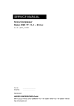
This example shows a poorly ventilated blower room. The orange arrows indicate air that is short circuiting or preheated cooling air at the
blower inlets.
Location
Ventilation
Electrical
Supply
Piping
Package
Integration
Building an
Efficient
System
Preventive
Maintenance
Safety
Advisories
Additional
Resources
www.us.kaeser.com Copyright © 2015 Kaeser Compressors, Inc. All Rights Reserved.
18
Appendices
Introduction
Ventilation
Receiving
Equipment
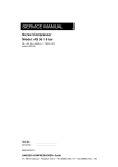
This example shows a properly ventilated blower room. The airflow is properly pulled across the blower packages and preheating of the
air is prevented. Although not shown here, it is also important to insulate any exposed discharged piping.
Location
Ventilation
Electrical
Supply
Piping
Package
Integration
Building an
Efficient
System
Preventive
Maintenance
Safety
Advisories
Additional
Resources
www.us.kaeser.com
Copyright © 2015 Kaeser Compressors, Inc. All Rights Reserved.
19
Appendices
{
www.us.kaeser.com Copyright © 2015 Kaeser Compressors, Inc. All Rights Reserved.
Electrical Supply
Important Warnings to Follow
Introduction
Electrical Supply
Receiving
Equipment
Before installing the blower package, check to ensure that your electrical service voltage matches the voltage on the blower nameplate
(located inside the electrical cabinet or the tag on the outside of the machine). Whether your blower is a dual or a tri voltage model, ensure
it is internally wired for the proper voltage.
!
Location
WARNING: Actual operating voltage must be within +/- 10% of blower nameplate voltage. Damage or failures due directly
or indirectly to insufficient or excessive voltage may not be covered under warranty. Consequently, Kaeser does not recommend operating a 230-volt system on a 208-volt circuit, for example.
Ventilation
Electrical
Supply
Kaeser recommends that each blower have its own dedicated electrical circuit and disconnect panel. This makes it possible to lock out and
tag out an individual piece of equipment without having to shut down other equipment that may be on the same panel. Disconnects should
eliminate power from the entire machine including all accessory equipment and instruments.
Electrical planning should include wiring for a master controller (multi-unit control device) if it is to be installed.
Piping
The blower should be properly grounded. Install an appropriately sized fuse or circuit breaker between the blower and main electric service. Consult the NEC and local electrical codes regulations for sizing guidelines.
Package
Integration
Building an
Efficient
System
Preventive
Maintenance
Safety
Advisories
Additional
Resources
www.us.kaeser.com Copyright © 2015 Kaeser Compressors, Inc. All Rights Reserved.
21
Appendices
Introduction
Electrical Supply
Receiving
Equipment
For variable frequency drive units, make sure that the power
supply transformer has a symmetrical, three-phase supply. In a
symmetrical three-phase supply, the phase angles and voltages
are all the same.
Location
Kaeser’s VFD units require a symmetrical power supply transformer with a wye configuration output. The circled configurations
indicate the two acceptable options for Kaeser’s VFD packages.
Ground wire should be equally sized to the power conductors.
Ventilation
Electrical
Supply
Piping
Package
Integration
Building an
Efficient
System
Preventive
Maintenance
Safety
Advisories
Tip:
Additional
Resources
Consult the NEC Code and local
regulations for guidance in
determining the acceptable limits
for ground electrode impedance.
www.us.kaeser.com Copyright © 2015 Kaeser Compressors, Inc. All Rights Reserved.
22
Appendices
Introduction
Electrical Supply
!
!
!
Receiving
Equipment
WARNING: Insufficient and/or improper grounding practices may lead to premature motor or VFD component failure.
Location
WARNING: Never use air piping or electrical conduit as a means of grounding.
Ventilation
Electrical
Supply
WARNING: All wiring and electrical connections must be performed by a qualified electrician in accordance with NEC and
local electrical codes. Supply conductors must be properly sized in accordance with all applicable national and local codes.
Piping
!
!
WARNING: The electrical service disconnect should be within sight of the blower and have an easily recognizable lock-out
tag.
Package
Integration
Building an
Efficient
System
WARNING: Some projects/installations will have limits on Total Harmonic Distortion (THD). THD limits must be clearly
defined by the methods outlined in IEEE 519. To achieve a desired THD value, additional external ancillary devices may be
required. These devices may either be a passive harmonic filter or an active harmonic filter. All Kaeser packages include
passive harmonic filters, but may not meet stringent project requirements.
Preventive
Maintenance
Safety
Advisories
Additional
Resources
www.us.kaeser.com Copyright © 2015 Kaeser Compressors, Inc. All Rights Reserved.
23
Appendices
{
www.us.kaeser.com Copyright © 2015 Kaeser Compressors, Inc. All Rights Reserved.
Piping
Impact of Pressure Drop and
Piping Materials
Introduction
Piping
Receiving
Equipment
Pressure drop directly affects blower temperature, and consequently, blower efficiency. Positive displacement blowers use
external compression. This means the more resistance there is
to airflow, the more energy they will consume. Additionally, while
a blower may be designed for 15 psig, it will only operate at 15
psig if there is enough resistance to the airflow that would require
15 psig pressure from the blower.
Location
Ventilation
Limiting pressure losses between the blower and the point of use
reduces the load on the blower as well as the kW consumption of
the machine, leading to lower operating temperatures and lower
electrical costs.
Electrical
Supply
Using larger diameter piping and eliminating elbows and T’s
whenever possible will help keep pressure drop as low as possible.
Piping
Above image shows an ample sized header with insulation to
limit heat transfer to the package cooling air.
“
Package
Integration
Building an
Efficient
System
Reducing pressure losses leads to lower operating
temperatures and lower electrical costs.
”
Preventive
Maintenance
Safety
Advisories
Additional
Resources
www.us.kaeser.com Copyright © 2015 Kaeser Compressors, Inc. All Rights Reserved.
25
Appendices
Introduction
Piping: Materials
Receiving
Equipment
Piping materials can also impact pressure drop as some materials are more prone to contaminant build-up.
Kaeser strongly cautions against using PVC piping. While it is a
cheap, readily, available material, it’s important to understand its
limitations. PVC piping is not recommended for operating temperatures above 140°F—this includes Schedule 40 and 80 piping.
In fact, any time the temperature is above 20°C (68°F), a thermal
derating factor must be applied to determine the maximum allowable working pressure. Additionally, pipe diameter affects the
derating factors as larger diameters are de-rated faster.
Location
“
If you have PVC piping or are considering using it, make sure to
understand how your particular installation’s operating conditions
will affect it. From a pressure drop, as well as a safety standpoint,
it’s probably best to use a different material.
PVC piping is not recommended for operating temperatures above 140°F—this includes Schedule 40
and 80 piping.
Ventilation
”
Electrical
Supply
Piping
Package
Integration
Building an
Efficient
System
Preventive
Maintenance
Burst PVC piping from a compressed air installation.
Safety
Advisories
More Resources:
Additional
Resources
For more information on the
dangers of using PVC piping, read
our blog entry.
www.us.kaeser.com Copyright © 2015 Kaeser Compressors, Inc. All Rights Reserved.
26
Appendices
Package Integration
{
www.us.kaeser.com Copyright © 2015 Kaeser Compressors, Inc. All Rights Reserved.
Blower and System Controls
Introduction
Package Integration
Receiving
Equipment
The most significant recent advances in blower technology have
been in package integration. A complete package design reduces
time spent engineering and purchasing individual components.
Additionally, each component is selected for optimal efficiency
and to work together to achieve the best package performance.
Integrated machines are often equipped with a suite of sensors
and onboard controller which monitor package performance and
health. As factory built machines, they come with full documentation, testing, and stated performance values, e.g. CAGI data
sheets.
Location
Ventilation
Since energy management is an important consideration for any
plant, proper controls should always be addressed in any blower
system. When addressing the issue of controls, there are individual unit controls to consider as well as broader system controls
that manage and coordinate the overall low pressure air system.
Electrical
Supply
Piping
Package
Integration
“
Building an
Efficient
System
A complete package design reduces time spent engineering and purchasing individual components.
”
Preventive
Maintenance
Safety
Advisories
More Resources:
Additional
Resources
Visit CAGI’s website for more
information on their testing
standards.
www.us.kaeser.com Copyright © 2015 Kaeser Compressors, Inc. All Rights Reserved.
28
Appendices
Introduction
Package Integration: Blower Controls
Receiving
Equipment
Individual unit controls can range from very basic packages with
essential pressure and vacuum gauges, to more comprehensive
packages that also include temperature, oil level and filter monitoring sensors, as well as remote monitoring capabilities.
Location
The choice depends greatly on the application and overall
sophistication level of the installation. Smaller, individual unit applications may require only basic controls. These local or individual unit control options are often either a fixed speed mode
or pressure regulation (VFD) where the unit maintains a desired
discharge pressure which is set locally. However, larger multiple
unit installations will want to take full advantage of the benefits
more in-depth controls provide. Especially if they are incorporating variable frequency drive units, master controllers, or if they
will be integrating the system into larger plant management
systems. Adaptive control schemes often offer the best efficiency
and performance and require more extensive unit controls.
Ventilation
Electrical
Supply
Piping
Package
Integration
“
Building an
Efficient
System
The choice of control depends greatly on the application and overall sophistication level of the installation.
”
Preventive
Maintenance
Safety
Advisories
Additional
Resources
www.us.kaeser.com
Copyright © 2015 Kaeser Compressors, Inc. All Rights Reserved.
29
Appendices
Introduction
Package Integration: System Controls
Receiving
Equipment
System controls vary in scope as well. When looking for a master
controller, consider its overall ability to integrate with your existing network communications. Does it have communications
interfaces that will easily connect with your SCADA system? If
your blower system is in an isolated location, consider looking for
a master controller with advanced remote monitoring and also
maintenance tracking and notification capabilities. As the Internet of Things continues to expand, package and communication
integration will become even more important to a plant’s energy
and asset management strategy.
Location
Ventilation
For more information, see the Master Controllers section.
Electrical
Supply
Piping
Package
Integration
“
Building an
Efficient
System
When looking for a master controller, consider its
overall ability to integrate with your existing network
communications.
”
Preventive
Maintenance
Safety
Advisories
More Resources:
Additional
Resources
Click here to read our blog entry
on the benefits of adaptive control
systems.
www.us.kaeser.com Copyright © 2015 Kaeser Compressors, Inc. All Rights Reserved.
30
Appendices
Building an Efficient System
{
www.us.kaeser.com Copyright © 2015 Kaeser Compressors, Inc. All Rights Reserved.
Package vs. System Efficiency
Introduction
Building an Efficient System
Receiving
Equipment
System engineers do their best to combat wasted energy by selecting energy efficient equipment. This has led to an increased
focus on energy and has helped spur innovations in blower
technology. Blower manufacturers are taking advantage of the
increasing interest in “wire-to-air efficiency” to promote these
new technologies, which can produce more efficient blowers for
certain performance points.
Location
Ventilation
Wire-to-air efficiency is simply the total energy used to provide
the specified flow and pressure and is expressed as a ratio of
the power to the flow. While this metric is relatively new to the
blower market, it is widely used for industrial compressors and
compressed air systems and is often referred to as specific
performance. Standards developed by groups like ISO, CAGI,
PNEUROP, and ASME provide testing guidelines for specific
performance comparison.
Electrical
Supply
Piping
Package
Integration
“
Building an
Efficient
System
Wire-to-air efficiency is simply the total energy used
to provide the specified flow and pressure and is
expressed as a ratio of the power to the flow.
”
Preventive
Maintenance
Safety
Advisories
More Resources:
Additional
Resources
Click here to download a copy of
our whitepaper on energy efficient
system design for wastewater
treatment plants.
www.us.kaeser.com Copyright © 2015 Kaeser Compressors, Inc. All Rights Reserved.
32
Appendices
Introduction
Building an Efficient System
Receiving
Equipment
Whether using the term wire-to-air or specific power, it is important to differentiate between each individual piece of equipment’s
efficiency and the overall system efficiency. Be careful of focusing on individual blowers instead of considering how each piece
will work with one another. Even if you select the most energy efficient blowers, if they aren’t properly applied and controlled, they
won’t yield the anticipated energy savings. This is why system
specific power is crucial in system design.
Location
Ventilation
System specific power takes into account the combined efficiency of all package, component, and in the case of variable frequency drive units, drive losses. With this machine information,
the combined performance of these machines can be allocated
to selected operating points of system demand to determine the
overall blower system performance. From here, these results can
be compared from solution to solution and across blower technologies.
Electrical
Supply
Piping
Don’t be fooled by the efficiency curves of an oversized blower. If
the blower will not be operating in its optimum performance curve
for your application, it will not deliver the energy efficient savings
you are expecting.
“
Package
Integration
Building an
Efficient
System
Even if you select the most energy efficient blowers,
if they aren’t properly applied and controlled, they
won’t yield the anticipated energy savings.
”
Preventive
Maintenance
Safety
Advisories
More Resources:
Additional
Resources
Our System Splitting video explains
how to design an energy efficient
blower system. Click here to view it.
www.us.kaeser.com Copyright © 2015 Kaeser Compressors, Inc. All Rights Reserved.
33
Appendices
Introduction
Building an Efficient System: Avoiding Control Gap
Receiving
Equipment
Using variable frequency drives (VFD’s) to optimize process low
pressure air systems offers many advantages. When properly applied, VFDs are an excellent choice in variable flow applications.
Blowers with VFDs can be used as stand-alone units and also
have an important role to play in larger more complex control
schemes. However in either case, sufficient attention must be
paid to factors such as proper connection methods, grounding,
managing electromagnetic interference (EMI) with communications, and proper parameterizing.
Location
Ventilation
Additionally, care must be taken in sizing the system to avoid
control gap, which causes system fluctuations and leads to unnecessary energy inefficiencies.
Electrical
Supply
Piping
Package
Integration
“
Building an
Efficient
System
Blowers with VFDs can be used as stand-alone units
and also have an important role to play in larger
more complex control schemes.
”
Preventive
Maintenance
Safety
Advisories
Additional
Resources
www.us.kaeser.com Copyright © 2015 Kaeser Compressors, Inc. All Rights Reserved.
34
Appendices
Introduction
Building an Efficient System: Avoiding Control Gap
Receiving
Equipment
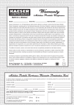
Control gaps are flaws in the system design that occur when the
control range of the variable frequency blower is not considered.
The majority of the time, this happens because a variable frequency drive blower is selected that is the same size or smaller
than the fixed speed blowers in the system.
This graph shows a system designed to avoid a control gap. It
can provide a steady airflow to meet a system design variable
(e.g. DO, pressure) through the flow range of the system since
it is properly sized and controlled by a system master controller,
like Kaeser’s Sigma Air Manager (SAM).
Location
“
Ventilation
Control gaps are flaws in the system design that occur when the control range of the variable frequency
blower is not considered.
”
Electrical
Supply
Piping
Package
Integration
Building an
Efficient
System
Preventive
Maintenance
Safety
Advisories
More Resources:
Control gaps can happen in any
type of installation with a VFD and
multiple fixed speed units.
Click here to read our
“Mind the Gap” blog entry.
www.us.kaeser.com Copyright © 2015 Kaeser Compressors, Inc. All Rights Reserved.
Additional
Resources
35
Appendices
Introduction
Building an Efficient Sytem: Master Controllers
Receiving
Equipment
If you have more than one blower feeding the same system, you
should consider system master controls. Master controllers control multiple blowers more efficiently while maintaining pressure
stability and rotating like-sized units to equalize service hours.
Location
A master controller’s computing capacity enables it to rapidly recognize changes in demand and always select the most efficient
combination of blowers to meet it.
Ventilation
Electrical
Supply
Piping
Package
Integration
Building an
Efficient
System
Preventive
Maintenance
Safety
Advisories
Tip:
Advanced master controllers can
monitor a specific system variable
(such as dissolved oxygen) and
trigger an alarm it the variable falls
below a specific threshold value.
www.us.kaeser.com Copyright © 2015 Kaeser Compressors, Inc. All Rights Reserved.
Additional
Resources
36
Appendices
Introduction
Building an Efficient System: Master Controllers
Receiving
Equipment
Benefits of Master Controllers:
Save Energy:
• Run blowers less
• Match air production to demand
• Reduce kW/cfm production
• Maintain blower package rotation schedule
• Minimize system pressure (if pressure regulating)
Reduced Maintenance Costs:
• Less cycling and switching = longer valve life
• Fewer motor starts = longer motor life
• Balanced blower package operating hours and fewer PM
visits
Location
“
Improve Operations with More Stable System Design Variable:
• Improve production equipment performance
• Less downtime due to pressure alarms
• Less scrap and product quality problems
Ventilation
The controls you implement will directly impact
your facility’s productivity and energy efficiency.
”
Electrical
Supply
Piping
Package
Integration
Kaeser’s Sigma Air Manager (SAM) makes it easy to control and
monitor up to 16 blowers. There are numerous control schemes
that you can easily customize to best meet your needs. The controls you implement will directly impact your facility’s productivity
and energy efficiency.
Building an
Efficient
System
Preventive
Maintenance
Safety
Advisories
More Resources:
Additional
Resources
Contact your local authorized
Kaeser representative for sample
control schemes and for help customizing a solution for your system.
www.us.kaeser.com Copyright © 2015 Kaeser Compressors, Inc. All Rights Reserved.
37
Appendices
Preventive Maintenance
{
www.us.kaeser.com Copyright © 2015 Kaeser Compressors, Inc. All Rights Reserved.
Keeping Your System Up and Running
Introduction
Preventive Maintenance
Receiving
Equipment
All mechanical and electrical equipment requires varying degrees of attention to ensure it operates efficiently. Since most
systems rely heavily on an uninterrupted supply of flow, it makes
sense to invest in preventive maintenance rather than suffer
downtime and repairs.
Location
It’s highly recommended to establish a regular maintenance routine to ensure proper operation of all parts of your blower system
and maintain a service log for each component. Regular preventive maintenance will ensure optimal performance and longer
equipment life.
Ventilation
Electrical
Supply
Your blower service manual has specific service recommendations. Follow all recommended maintenance procedures. Taking
the few minutes to perform these checks will maintain the quality
of your flow and equipment, reducing the costs associated with
repairs and lost production.
Kaeser’s integrated and screw blower packages come equipped
with computerized controllers which monitor equipment health
and operation in real time, as well as provide maintenance interval reminders. They offer the capability to send these messages
to plant control systems or provide messaging to plant personnel
responsible for the equipment.
www.us.kaeser.com Piping
Package
Integration
“
Copyright © 2015 Kaeser Compressors, Inc. All Rights Reserved.
Building an
Efficient
System
Regular preventive maintenance will ensure optimal
performance and longer equipment life.
”
Tip:
More Resources:
Need a service manual? Contact
your local authorized Kaeser
representative.
Click here to take flight and explore
our screw blower packages.
Preventive
Maintenance
Safety
Advisories
Additional
Resources
39
Appendices
Introduction
Preventive Maintenance: General Guidelines
Receiving
Equipment
Below is a general list of maintenance items to monitor. Check
your service manual for more recommendations. Keep in mind
that, based on your application and operating environment, you
may need to adjust the frequency. Contact your local authorized
Kaeser representative with any additional questions.
Location
• Check oil level via sight glasses: at least monthly
• Check belt tension visual indicator: at least monthly
• Tighten electrical connections: after first 50 hours and annually thereafter
• Change oil: after first 500 hours and at least annually thereafter
• Check diff pressure indicator on silencer and enclosure at
least monthly
• Replace air inlet filter/silencer: at least annually
• Check safety valve and other safety device operation: annually
• Lubricate/replace motor bearings: at least every three years
(permanent)/ five years (regreasable)
• Replace belt set: at least every three years
• Install check plate kit: every three years
• Install start valve kit: every three years (if applicable)
• Check compensator/ hose lines: every eight years
Ventilation
Electrical
Supply
Piping
Package
Integration
“
Building an
Efficient
System
Keep in mind that, based on your application and
operating environment, you may need to adjust the
frequency of the service intervals.
”
Preventive
Maintenance
Safety
Advisories
Additional
Resources
www.us.kaeser.com Copyright © 2015 Kaeser Compressors, Inc. All Rights Reserved.
40
Appendices
Introduction
Preventive Maintenance: General Guidelines
Receiving
Equipment
In addition to regular checks by your plant personnel, an effective preventive maintenance program should include regular professional
servicing. Standard services are usually performed at manufacturer recommended intervals, but may be recommended more often depending on the usage and operating environment.
Location
Kaeser has a factory-trained, national distribution network that is always ready to assist you with your maintenance needs. Contact your
local authorized Kaeser representative to schedule a service appointment.
Ventilation
!
!
WARNING: Lack of proper maintenance may invalidate any warranty claims if failures are directly related to a
failure to perform routine preventive maintenance. A preventive maintenance contract with your local Kaeser representative is a means of having this work carried out properly.
Electrical
Supply
Piping
CAUTION: Before performing any work, be sure to follow OSHA recommendations for electrical lock-out/tag out.
Package
Integration
Building an
Efficient
System
Preventive
Maintenance
Safety
Advisories
Additional
Resources
www.us.kaeser.com Copyright © 2015 Kaeser Compressors, Inc. All Rights Reserved.
41
Appendices
{
www.us.kaeser.com Copyright © 2015 Kaeser Compressors, Inc. All Rights Reserved.
Safety Advisories
Health and Safety Considerations
Introduction
Safety Advisories: Health and Safety Considerations
Receiving
Equipment
Installation should be conducted in a safe manner in accordance with OSHA and appropriate local regulations. Compressed air can be
dangerous and should never be directed towards people. Improper and unsafe contact with compressed air can cause eye damage, subcutaneous embolisms, and other serious injuries, including death.
Location
When working in a lift, technicians should use a proper harness and rigging.
Qualified technicians must perform electrical work in a safe manner using UL approved materials and properly insulated tools, equipment,
and appropriate personal protective equipment (PPE) for the work. All applicable local, state, and national regulations must be followed.
Ventilation
The blower system must be installed so that normal operation poses no threat to work health or safety. The system must be sufficiently
ventilated so that it poses no health threat to persons nearby.
Electrical
Supply
Hearing protection must be worn in accordance with OSHA standards. Where applicable, prominently display signs warning of noise hazards. Blower operating sound levels are listed in Kaeser service manuals.
Follow OSHA recommendations for electrical lock-out/tag out.
Piping
Follow all safety recommendations in the manufacturer’s service manual.
Package
Integration
Building an
Efficient
System
Preventive
Maintenance
Safety
Advisories
Additional
Resources
www.us.kaeser.com Copyright © 2015 Kaeser Compressors, Inc. All Rights Reserved.
43
Appendices
Additional Resources
{
www.us.kaeser.com Copyright © 2015 Kaeser Compressors, Inc. All Rights Reserved.
More Tips and Resources
Introduction
Additional Resources
Receiving
Equipment
• www.kaesertalksshop.com: Our company blog features posts on a wide range of compressed air topics written by our subject matter
experts and is updated regularly. You can also sign up to follow the blog to receive updates whenever there is a new post.
Location
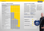
• www.kaeser.com/cagi: Kaeser is a member of the Compressed Air and Gas Institute (CAGI), a non-profit organization of competitive
companies that manufacture air and gas compressor and related equipment.
• www.kaeser.com/resources: This webpage has a collection of technical articles, material safety data sheets (MSDS), tools, presentations, and much more.
Ventilation
• www.kaeser.com/whitepapers: Our collection of whitepapers provide in-depth technical information on challenges those in the compressed air industry are currently facing.
Electrical
Supply
• Our online Kaeser Toolbox has a number of handy tools for making common compressed air calculations.
Piping
Package
Integration
Building an
Efficient
System
Preventive
Maintenance
Safety
Advisories
Additional
Resources
www.us.kaeser.com Copyright © 2015 Kaeser Compressors, Inc. All Rights Reserved.
45
Appendices
{
www.us.kaeser.com Copyright © 2015 Kaeser Compressors, Inc. All Rights Reserved.
Appendices
Charts and References
Introduction
Appendix A: Elevation Derate Chart for Motors
Altitude
(ft.)
1.0
SF
1.15
SF
3,300 - 9,000
93%
100%
9,000 - 9,900
91%
98%
9,900 - 13,200
86%
92%
13,200 - 16,500
79%
85%
13,200 - 16,500
79%
85%
over 16,500
Receiving
Equipment
Location
Ventilation
Electrical
Supply
Consult Manufacturer
Piping
Package
Integration
Building an
Efficient
System
Preventive
Maintenance
Safety
Advisories
Additional
Resources
www.us.kaeser.com Copyright © 2015 Kaeser Compressors, Inc. All Rights Reserved.
47
Appendices
Introduction
Appendix A: Elevation Derate Chart for Motors
Receiving
Equipment
Motor derating:
Three-phase asynschronous motors Class F windings are designed by Kaeser so that they are loaded to Class B at air cooling temperatures up to only 40°C, elecations up to 1000m above sea level and their mentioned rated power.
Location
If these limitations are exceeded, the motor must be de-rated so that the motor windings used are Class F and not Class B.
Mains voltage fluctuations, particularly under-voltage, can then lead to motor overheating, as there is no longer a reserve.
Ventilation
These diagrams should help in determining the motor shaft power depending on ambient temperature and elevation.
If derating is necessary because of simultaneously higher ambient temperature and elevation, the motor shaft power values must be multipled together.
100
100
95
95
90
90
85
85
Piping
Package
Integration
80
40
45
50
55
60
80
1000
1750
2500
3250
Building an
Efficient
System
4000
100
100
95
95
90
90
85
85
80
105
Electrical
Supply
110
www.us.kaeser.com 115
120
125
130
135
140
Copyright © 2015 Kaeser Compressors, Inc. All Rights Reserved.
80
3200
Preventive
Maintenance
Safety
Advisories
Additional
Resources
5200
7200
9200
11200
13200
48
Appendices
Introduction
Appendix B: Helpful Formulas and Calculations
Receiving
Equipment
Thermal Outout of Rotary Blowers:
QMOT. Thermal output of the drive motor
Motor power:
3 - 7.5 kW
ca. 14%
11 - 18.5 kW ca. 10%
22 - 55 kW
ca. 7%
75 - 200 kW
ca. 5%
The percentage values relate to the corresponding shaft power of the motors. Because of the V-belt transmission loss, these can be
calculated as 1.03 times the block power consumption.
Location
Ventilation
The thermal output of the motor increases by about 1% when under partial load down to half rated power.
Electrical
Supply
Of the motor is driven from a frequency converter, the thermal output increases a further 3 - 6%.
QKR Thermal output of V-belt transmission: ca. 3% of motor shaft power
Piping
QB Blower block thermal output: 1 - 2% of block power consumption
QSD Silencer thermal output: 1 - 2% of block power consumption
Package
Integration
Overall thermal output:
QCOMBINED ≈
n
ΣQ
i=1
MOT.
+ QKR + QB + QSD [kW]
Building an
Efficient
System
Pipework Thermal Output (not insulated):
QLINE ≈ 3.2 · 10-5 · d · l · (0.6 · T2 - TAMB) [kW]
Preventive
Maintenance
Because of the high flow velocity, the heat take-up of the gas is insignificant and can be ignored.
d = pipe diameter in [mm]
l = pipe length in [m]
T2 = blower discharge temperature in [°C]
TAMB = ambient temperature in [°C]
Safety
Advisories
Additional
Resources
www.us.kaeser.com Copyright © 2015 Kaeser Compressors, Inc. All Rights Reserved.
49
Appendices
Introduction
Appendix B: Helpful Formulas and Calculations
Volume flowing into the blower room:
V'BLOWER ROOM = 3600 · (QCOMBINED + QLINE )
ρ · cρ · ∆T
ρ = Cooling air density (1.19 kg/m3 at 20°C, 1 bar)
cρ= Thermal capacity of air 1.0 kJ/kgK
∆T= Room temperature rise 5-10 K
Receiving
Equipment
ϑoutside
Location
Q'blower
V'room
V'bl
Airflow into the room not necessary if:
n
V'BLOWER ROOM ≤
V'1_Blower [m3/h]
i=1
Airflow into the room necessary if:
n
V'BLOWER ROOM >
V'1_Blower [m3/h]
i=1
owe
Σ
V'intake
Ventilation
ϑroom
r
Q'line
Electrical
Supply
Σ
Exhaust airflow from the room:
Blower air intake from the room (Figure 1):
n
V'INTAKE = V'BLOWER ROOM V'1_Blower
i=1
(If V'INTAKE = 0, then V'BLOWER ROOM = V'1_Blower)
Σ
Blower air intake from outside the room (Figure 2):
V'INTAKE = V'BLOWER ROOM
Piping
Package
Integration
ϑoutside
Q'blower
V'room
Effective cross-section areas of ventilation openings:
AEFF = V'BLOWER ROOM [m2]
10800
Based on the recommended airflow rate of 3 m/s.
Building an
Efficient
System
V'intake
Preventive
Maintenance
ϑroom
Q'line
Safety
Advisories
Additional
Resources
www.us.kaeser.com Copyright © 2015 Kaeser Compressors, Inc. All Rights Reserved.
50
Appendices
The Air Systems Specialist
We earn our customers’ business by supplying superior quality equipment and
services. Our products are designed for reliable performance, easy maintenance, and energy efficiency. Prompt and dependable customer service, quality assurance, training, and engineering support contribute to the value our
customers have come to expect from Kaeser. Our employees are committed to
implementing and maintaining the highest standards of quality to merit customer
satisfaction. We aim for excellence in everything we do.
www.us.kaeser.com Copyright © 2015 Kaeser Compressors, Inc. All Rights Reserved.
USBSIGEB 09/15
Kaeser Compressors, Inc.
511 Sigma Drive
Fredericksburg, Virginia 22408 USA
Phone: 540-898-5500
Toll Free: 800-777-7873
Email: [email protected]