1
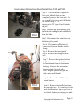
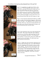
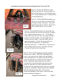
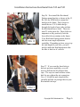
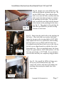
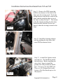
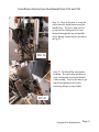
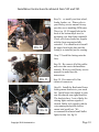
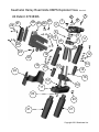
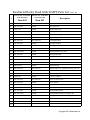
Installation Instructions for the Kewlmetal Harley Pro Street
Rake kit Item 542 AND 543
US Patent #7438307
CAUTION – Kit 542 is for 21 -26 inch front wheels ONLY when installed
on a motorcycle!
CAUTION – Kit 543 is for16 or 18 inch front wheels ONLY when installed
on a motorcycle!
CAUTION - Kit 542 is for 16 or18 inch front wheels ONLY when installed
on a Trike or Sidecar.
Congratulations on your purchase of your new Kewlmetal bolt on pro street
rake kit. Please read these instructions completely before beginning. You
should have the service manual for your bike for a project of this magnitude.
These instructions will provide a step by step sequence of dis-assembly and
re-assembly and all details needed to install the Kewlmetal specific parts and
assemblies. These instructions do not describe in detail the dis-assembly and
re-assembly of the Harley Davidson specific parts and assemblies. A good
example of that is the throttle cables. Since details can be model/year
specific such as cable operated versus throttle by wire, it is assumed the
installer has first hand knowledge and/or the appropriate service manual
required to accomplish this task
There are 2 special tools you will most likely need.
1)
The Ignition switch alignment tool.
2)
A bearing puller to remove the bearing races from the steering neck.
Copyright 2010 Kewlmetal Inc.
Page 1
Installation Instructions Kewlmetal Item 542 and 543
Step 1. You will need to support the
bike on a lift such that you can
completely remove the front end. We
use a small jack screw type lift like the
one shown in fig 1. A
motorcycle/ATV type lift will also do
the job.
FIG 1
Step2. Remove the front fairing (front
half with the headlight) and windshield
from the bike.
Step 3. Dis-connect the main fuse near
the battery/fuse panel.
Step 4. Dis-connect all electrical
connectors between the bike and the
fairing.
Step 5. Remove the turn signals.
Step 6. Remove the fairing from the
bike.
Step 7. Remove the ignition lock per
the Harley service manual. Remove
the Instruments from the instrument
housing. Remove the instrument
housing plastic from the bike.
Don’t forget to protect the gas tank
with a nice thick blanket.
Step 8. Remove the OEM fairing
mount bracket
FIG 2
Step 9. Remove the handle bars from
the top triple tree. You can lay the bars
back on the tank as long as you have a
nice thick blanket protecting your tank.
Copyright 2010 Kewlmetal Inc.
Page 2
Installation Instructions Kewlmetal Item 542 and 543
Step 10. Remove the Brake Calipers.
Step 11. Remove the front wheel.
Step 12. Remove the Front Fender.
Step 13. Remove the forks.
Step 14. Remove the brake manifold from
the bottom triple tree.
Step 15. Remove triple trees from bike.
FIG 3
Step 16. Now remove the bearing races
from the frame. You will most likely
need a bearing race puller to accomplish
this task.
FIG 4
Step 17. Now un-package your new
Kewlmetal Kit. The kit is shipped
assembled so take note on how
everything goes together.
FIG 5
Copyright 2010 Kewlmetal Inc.
Page 3
Installation Instructions Kewlmetal Item 542 and 543
Step 18. Assemble the top and bottom blocks to the
frame neck. DO NOT install the inner spacer tube or
front spacer tube YET! The objective of this step is to
fully seat the BOTTOM block into the bearing race
seat, and then remove the top block, THEN install the
spacer tubes. Install the main ¾ inch bolt and washer
from the bottom and tighten it down until it draws the
top and bottom blocks fully into the bearing race cups.
FIG 6
FIG 7
Step 19. Now loosen the main bolt a bit and use a rubber
mallet to adjust the left and right alignment of the bottom
block to the frame. The alignment of the top block is not
important at this step. Now back out the main bolt a few
turns and rap on it from the bottom with a hammer and
drive the top block back out of the frame.
Step 20. Now install the inner spacer shaft and the front
spacer shaft. The cutout on the inner spacer shaft (if
yours has one) is for bikes with the steering lock built
into the steering head on the bike. This cutout goes
down and back. The tabs on the inner spacer shaft must
engage the slots in the blocks. The flat on the front
spacer shaft goes up and back.
Step 21. Tighten the main bolt slowly drawing the top
block into the top bearing cup. Use a rubber mallet to
adjust the alignment of the top block as the assembly
comes together. The front shaft, bottom blocks, and
top block should all line up once the top block is all
the way down. Once the main bolt is tight, the front
shaft should become trapped and tight. Once you are
satisfied with the alignments, final torque the main
bolt to 200 ft-lbs.
FIG 8
Copyright 2010 Kewlmetal Inc.
Page 4
Installation Instructions Kewlmetal Item 542 and 543
Step 22. Remove the OEM risers and
ground wire from the stock top triple tree
and re-install them on your Kewlmetal top
tree. The grounding screw is underneath on
your Kewlmetal tree.
FIG 9
Step 23. NOTE: BEFORE installing your
triple trees on the bike you must pack the
steering bearings with grease. Any good
wheel bearing grease will do. We prefer a
fully synthetic grease on our builds.
Step 24. Now install the bottom tree on the bike, the
top of the shaft gets the top dust seal, and the 2 smaller
nuts. Tighten the bottom nut to 10 – 12 FT-LBS of
torque then work the lower tree back and forth and retorque to seat the bearings. Use the double nuts to
lock the top nut in place. After the double nuts are
tightened together, re check the amount of force it
takes to turn the bottom tree. It should take
somewhere between 2 –3 LBS of force to turn the tree
when pulling from the center of the fork tube hole.
You can use a fish scale to check this.
FIG 10
FIG 11
Step 25. Now install the top tree with the pinching
fat fork tubes in place. BEFORE installing the top
tree, be sure you have the clutch cable and throttle
cable routed properly, the cables generally will pass
in front of the top tree, and between the forks and
frame. Install the washer and nut on top of the
steering shaft. Only hand tighten the top nut at this
point, we want that to be loose until the forks are
installed into the pinching fat fork tubes so everything
can line up. Install the 12mm flat head bolts and that
hold the pinching fat fork tubes to the top tree.
Rotate the pinching fat fork tubes so that the fairing
mount studs point straight out.
Copyright 2010 Kewlmetal Inc.
Page 5
Installation Instructions Kewlmetal Item 542 and 543
FIG 12
Step 26. Now install the Kewlmetal
Fairing mount bracket as shown in fig 12.
Re-Use the OEM bolts to mount the
bracket to the frame. Don’t forget to
install the two 3/8-16 bolts that go
through the bracket lower tabs and into
the Kewlmetal lower block. These are
item 23 on the parts list. These bolts are
important as they positively lock the
lower block from rotation in the frame.
Your Kewlmetal fairing mount bracket
also has some angle adjustment
capability. Depending on how you set up
the ride height of your bike, you will
need to make this final adjustment after
the bike is back on it’s wheels.
Step 27. If you want the front forks to
have air pressure capability, you will
need to drill thru the Kewlmetal fork
caps. The caps are made without a thru
hole for use without the air connection.
Use a 3/16 drill bit and a hand drill to
carefully drill the air passage thru on your
Kewlmetal fork caps.
FIG 13
Copyright 2010 Kewlmetal Inc.
Page 6
Installation Instructions Kewlmetal Item 542 and 543
FIG 14
FIG 15
Step 28. Replace the stock OEM fork caps
with the Kewlmetal extended fork caps. Re
use the OEM O-ring. Now slide the lower
fork covers onto the forks, and then slide the
forks up into the bottom triple tree and into
the pinching fat fork tubes. The top of the
fork cap should come flush with the bottom
of the cutouts in the pinching fat fork tubes
(see fig 15). The cutouts in the pinching fat
fork tubes go INSIDE to provide steering
clearance to the frame.
Step 29. Snug down the pinch bolts on the pinching fat
fork tubes. Once both forks are in place, then final
torque the top nut on the steering shaft to 50 FT-LBS,
lastly tighten the lower tree pinch bolts while holding
the lower fork covers up flush with the bottom tree.
You should rotate the lower fork covers so the slots in
the fork covers align themselves with the slots in the
lower triple tree. Now you can final torque the Lower
Triple Tree pinch bolts to 20 FT-LBS and the ¼-20 Fat
fork tube pinch bolts to 10 FT-LBS. Go up and down
several times until they are completely snugged down.
Step 30. Now install the OEM air fittings onto
the top of your Kewlmetal fork caps. Reconnect the air lines and check for binding and
pinching when turning the handle bars from
stop to stop.
FIG 16
Copyright 2010 Kewlmetal Inc.
Page 7
Installation Instructions Kewlmetal Item 542 and 543
FIG 17
Step 31. Remove the OEM straps that
hold the wire harness to the front of the
frame near the steering neck. Zip tie the
wiring harnesses up into the corner of the
frame and the triangular plate on top of
the frame as shown in fig 17. The cutouts
in the Kewlmetal pinching fat fork tubes
should provide clearance for the wire
harness when the steering is turned to the
stops..
Step 32. Install the 4 fairing adaptors
into the pinching fat fork tubes with
some SEMI permanent loctite.
FIG 18
FIG 19
Step 33. re-install the Ignition on the
top triple tree. Re-Install the handle
bars and risers. Before installing the
risers, don’t forget to install the
ground wire that grounds the handle
bars. You can re-use the OEM wire.
There is a 10-24 tapped hole in the
bottom of the Kewlmetal top tree for
this purpose.
Copyright 2010 Kewlmetal Inc.
Page 8
Installation Instructions Kewlmetal Item 542 and 543
Step 34. Now is the time to route the
wires from the main harness and the
handle bars. The wires that need to
go up into the fairing need to cone
forward through the top and middle
of the fairing mount bracket as shown
in Fig 20.
FIG 22
FIG 20
Step 35. Re-Install the instrument
housing. Pay particular attention to
wire routing and clutch and throttle
cable routing. Now is the time to get
that all straightened out before
buttoning things up any further.
FIG 21
Copyright 2010 Kewlmetal Inc.
Page 9
Installation Instructions Kewlmetal Item 542 and 543
FIG 25
FIG 22
Step 36. re-install your front wheel,
fender, brakes, etc. Please refer to
your Harley service manual for any
specifics on re-installing OEM parts.
There is a 1/4 20 tapped hole in the
back of the bottom triple tree for
mounting your front brake manifold.
Check your lower brake line lengths
with the front suspension fully
extended. You should wait to install
the upper front brake line until the
fairing is re-installed just for routing.
Step 37. Install the fairing onto the
bike.
Step 38. Re connect all of the cables
and wires that run to the handlebar
controls. Refer to your Harley service
manual for model specific
instructions.
FIG 23
FIG 24
Copyright 2010 Kewlmetal Inc.
Step 39. Re connect all of the
electrical connectors.
Step 40. Install the Kewlmetal lower
fairing mount brackets to your crash
bar. Install some turn signals to your
new Kewlmetal turn signal brackets.
The brackets have 2 sets of holes for
driving lights and turn signals if
desired. Bullet style signals with the
wire running through the hollow
mount stud work best. We
recommend Kewlmetal small bullet
lights for this. See fig 24.
Page 10
Installation Instructions Kewlmetal Item 542 and 543
Step 41. Now is the time to wire your new front turn signals. Re-Install the main
fuse and turn on the ignition and test all the electrical systems to make sure
everything is working before we final install the front headlight shroud and fairing.
Step 42. Adjust the headlights down almost as far as they will go using the
headlight adjuster screws. The screws will be out almost as far as they will go.
IMPORTANT NOTE : You will have to trim the length of these screws because
they will hit the inner fairing and not allow you to properly re-install the front
fairing half when they are adjusted all the way out. Using a die cutter, you should
cut off the screws removing just about all of the hex portion of the adjuster screw.
Step 43. Once you have tested all the electrical, re-install the front fairing with
the headlight back on the bike. Don’t forget to plug in the headlight when you
are doing this. Re-install all the fairing screws per your Harley shop manual.
Step 44. Final install all the brake lines and bleed the front brake system. You
should take this opportunity to drain all the old brake fluid and start with fresh fluid.
A power brake bleeder is a BIG help when bleeding a newly assembled brake
system. Refer to your service manual for model specific instructions.
Step 45. Double check all fasteners. Check for proper brake operation. Check
for proper clutch and throttle operation with the bars full left and full right.
Check no wires are being pinched or pulled.
Now take it outside for a test ride and be KEWL!
Copyright 2010 Kewlmetal Inc.
Page 11
Kewlmetal Harley Road Glide KMPS Exploded View
US Patent #7438306
29
1
2
23
26 25 28
27
Gen 3 Kit
3
1
4
6
23
5
9
7
8
11
28
10
23
12
12
29
13
14
13
15
14
22
18
16
19
17
20
20
21
21
Copyright 2011 Kewlmetal Inc.
Kewlmetal Harley Road Glide KMPS Parts List Gen 3 Kit
#
Part No. For 21-26 Inch
Front Wheel Kit
Part No. For 16-18 Inch
Front Wheel Kit
Item 542
Item 543
Description
1
OTS-1349
SAME
12mm FHCS
2
MC-100-1246
SAME
Nut, Upper Tree
3
OTS-1145
SAME
Washer, Upper Tree
4
MC-100-1599
MC-100-1586
Top Triple Tree
5
MC-100-1245
SAME
Nut, Lower Steering Stem
6
AB-99-3520
SAME
Top Bearing
7
MC-100-1597
MC-100-1584
Top Adaptor Block
8
MC-100-1587
SAME
Front Spacer Shaft
9
MC-100-1588-1
SAME
Pinching Fat Fork Tube, LH
10
MC-100-1593
SAME
Inner Spacer Tube
11
MC-100-1588-2
SAME
Pinching Fat Fork Tube, RH
12
MC-100-1637
SAME
Fairing Mount Stud
13
OTS-1335
SAME
¼-20 X 1 SHCS
14
MC-100-1591-3
MC-100-1591-5
Fork Extension Cap
15
MC-100-1404
SAME
Steering Shaft
16
AB-99-3519
SAME
Bottom Bearing
17
MC-100-1598
MC-100-1585
Bottom Triple Tree (with shaft, bearing, and seal)
18
OTS-1321
SAME
¾-10 Hex Head Grade 8 Bolt
19
MC-100-1596
MC-100-1583
Lower Adaptor Block
20
OTS-1309
SAME
5/16-18 X 1 SHCS
21
MC-100-1538
MC-100-1589
Lower Fat Fork Covers
22
MC-100-1595
SAME
Lower Shroud
23
OTS-1353
SAME
3/8-16 X .75
24
OTS-1337
SAME
3/8 Flat Washer
25
MC-100-1640
SAME
Fairing Mount Bracket
26
MC-100-1641-1
SAME
Fairing Mount Bracket Front Flange, RH
27
MC-100-1641-2
SAME
Fairing Mount Bracket Front Flange, LH
28
OTS-1352
SAME
3/8-16 Nut
29
OTS-1354
SAME
3/8 Flat Washer
31
Copyright 2011 Kewlmetal Inc.