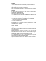
1
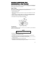
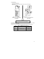
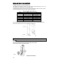
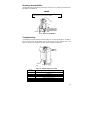
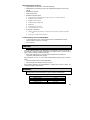
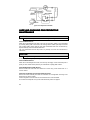
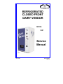
REFRIGERATED CLOSED FRONT DAIRY VENDOR MODEL: 3087 Service Manual A10081 June 1998 P/N 4208092 Rev. B Table of Contents SPECIFICATIONS .................................... 1 Physical Dimensions.............................. 1 Electrical................................................ 1 Refrigeration System ............................. 1 Capacities.............................................. 1 Pricing ................................................... 1 Coinage ................................................. 1 INTRODUCTION....................................... 2 UNPACKING............................................. 2 INSTALLATION ........................................ 3 Grounding & Electrical ........................... 3 Power Switch......................................... 4 CONTROLLER FUNCTIONS .................... 4 Sales Mode........................................ 5 Vend Cycle ........................................ 5 LEDs.................................................. 5 Empty Condition Check ..................... 5 Jammed Motor Condition ................... 6 Vend Mode Diagnostics Codes .......... 6 Service Mode ........................................ 6 Button Configuration and Functions ... 6 Accessing the Service Modes ............ 7 Exiting the Service Mode ................... 7 Service Mode - Level 1 .......................... 7 Reset Accounting Data .....................10 Service Mode - Level 2 .........................10 Assign Motors to Selection................10 Verify Motor Assignment ...................11 No Change Vending..........................11 Setting Keypad Configuration ...........11 Service Mode - Level 3 .........................11 Sensor Test ......................................11 Force Vend .......................................11 Multi-Vend ........................................12 Maximum Change.............................12 Bill Escrow ........................................12 Refrigeration Settings .......................12 LOADING PRODUCTS............................13 CHANGING AUGER TIMING, TRAY CONFIGURATION & TRAY SPACING ....15 Auger Timing ........................................15 Tray Spacing ........................................15 COIN MECHANISM .................................16 Option Switch Setting ...........................16 DOLLAR BILL VALIDATOR....................18 Removing Accepted Bills ......................19 Troubleshooting....................................19 Clearing Jams and Cleaning.................20 REFRIGERATION FUNCTIONS & OPERATION............................................20 Refrigeration Control ............................20 Refrigeration Troubleshooting...............20 Compressor will not start ..................21 Compressor trips on Overload ..........21 Noisy or vibrating unit .......................22 Unit short cycles ...............................22 Unit operates long or continuously....22 Refrigerated space too cold ..............22 Refrigerated space too warm ............23 Troubleshooting circuits with MultiMeter ................................................23 CARE AND CLEANING FOR PREVENTIVE MAINTENANCE ...............24 Clean Cabinet Interior:......................24 Clean Cabinet Exterior:.....................24 Clean Refrigeration Intake Screen: ...24 Clean the condenser coil and rear exhaust screen: ................................24 PARTS ORDERING PROCEDURE .........25 BEFORE CALLING FOR SERVICE.........26 SCHEMATIC............................................27 Record the Model Number and Serial Number of your machine below. The Model and Serial numbers are needed for you to obtain quick service and parts information for your machine. The numbers are given on the identification plate located on the back side of the cabinet of the machine. MODEL NUMBER: ________________________________________________________ SERIAL NUMBER: ________________________________________________________ ii SPECIFICATIONS Physical Dimensions Width Depth Height Weight IMPERIAL 41 Inches 37 Inches 72 Inches 771 Pounds METRIC 1.05 Meter 0.94 Meter 1.8 Meter 350.4 Kg Electrical 115 Volt AC: 230 Volt AC: Transformer: 60 Hz, 7.5 Amps (± 10%) 50 Hz, 3.75 Amps (± 10%) 24 Volt AC, 4 Amp at 50% Duty Cycle Refrigeration System Type: Controls: Refrigerant: Charge: 1/3 Hp Hermetically Sealed Electronic R-134a 7.7 Ounces Capacities Capacity will depend on the tray configurations but will allow for a: Maximum of 6 trays Maximum of 54 motors Maximum of 36 Selections (12 standard) Maximum of 24 motors per selection Pricing Five digit, dependent on scaling factor from either the Coin Mechanism, Bill Validator, or Card Reader Coinage Any MDB peripheral device 1 INTRODUCTION This manual provides service and programming instructions for the proper operation of the Refrigerated Closed Front Dairy Vendor. This vendor has a microprocessor-based control system to control and monitor the vending machine, coin mechanism, bill validator, card reader and other configured options. The controller can operate up to 60 motor-driven augers for product delivery. The vendor is configured at the factory to most customer specifications. Each vendor consists of five or six trays with a maximum of 9 motors on each tray for a maximum of 54 motors. The controller can be programmed (refer to the Button Configuration Section) for a maximum of 36 different selections (12 standard) with up to 24 motors per selection. Features include: • Multi Drop Bus (MDB) coin and currency handling mechanisms • DEX/UCS for MIS data transfer using the Vending Industry Data Transfer Standard • Self-diagnostics and cash accountability • Force Vend and Multi Vend features • Hermetically sealed refrigeration system with R-134a refrigerant • Programmable electronic control of the refrigeration and heater • Relay-controlled evaporator fans • Motorized delivery, electronically controlled • Motor time-out and overload protection is provided, including the delivery door motor. CAUTION: This vendor utilizes DC motors. Do not attempt to turn augers by hand. Motor damage could occur. • • Audible feedback indicates when a product has been vended or when an error condition exists. No change or loss of program/memory because a power failure or voltage spike. UNPACKING This vendor was thoroughly inspected before leaving the factory and the delivering carrier has accepted this vendor as their responsibility. Note any damage or irregularities at the time of delivery and report them to the carrier. Request a written inspection report from the claims inspector to file any claim for damage. File the claim with the carrier (not the manufacturer) within 15 days after receipt of the machine. Carefully remove the outside packing material so as not to damage the finish or exterior of the machine. Adhesive residue can be removed with denatured alcohol or common household vinegar. Inspect the machine for concealed shipping damage. Report any damage hidden by the shipping material directly to the delivering carrier on a hidden damage report. Record the model number and serial number of the vendor for your records. These numbers can be found on the Serial Plate on the rear of the cabinet and/or inside the vendor. Refer to these numbers on all correspondence and inquiries pertaining to this vendor. Remove the Knock-A-Way Support by placing a 2x6 under the vendor, inserting a screwdriver or prying tool into the groove and splitting it in two. Turn the leveling screws in as far as possible. See Figure 1. 2 Figure 1. Removing the Knock-A-Way Support INSTALLATION Consult local, state and federal codes and regulations before installation of the vendor. Position the vendor in its place of operation no further than six feet (1.83 m) from the power outlet or receptacle Leave at least six inches (15 cm) of space between the back of the machine and any wall or obstruction for proper air circulation. Retrieve the keys to the vendor from the coin return cup. Open outer door and remove all internal packing material. Check that the door will open fully without interference. Level the vendor, making sure all levelers are touching the floor. The vendor must be level for proper operation and acceptance of coins through the coin mechanism. Grounding & Electrical Before connecting the vendor, the integrity of the main electrical supply must be checked for correct polarity, presence of ground (earth) and correct voltage. These checks should be repeated at 6-month intervals with the routine safety electrical testing of the vendor itself. For proper operation of any equipment utilizing electronically controlled components, the equipment should be placed on an isolated or dedicated noise-free circuit. For 115-Volt vendors the circuit should be a minimum 15 Amp, 60 cycle, properly polarized and grounded. For 230-Volt vendors the circuit should be a minimum 7.5 Amp, 50 cycle, properly polarized and grounded. To verify that the receptacle is properly grounded and polarized, insert one probe of a Multi-Meter (set to check AC line voltage) or a test light in the ground terminal (hole) and the other probe into the hot terminal of the outlet. CAUTION If the receptacle is not properly grounded or polarized, you should contact a licensed electrician to correctly polarize and/or ground the receptacle to ensure safe operation. A noise suppressor has been installed in this machine to compensate for any signal noise that could interfere with the normal operation of the controller. 3 A10116 Figure 3. 115-Volt Outlet Figure 2. 230-Volt Outlets Power Switch The vendor has a Power Switch operated by the outer door. The switch is located in the lower left corner of the cabinet. When the door is closed, the switch is placed ON, putting the vendor in the Sales Mode. When the door is opened, the switch is placed OFF, removing power to the machine. See Figures 4 and 5. To operate the machine with the door open, the switch must be manually placed in the ON position: pull the switch stem to the extreme extended position. See Figure 5. A10138 A10138 Figure 4. Location of Interlock Switch Figure 5. Interlock Switch Operation CONTROLLER FUNCTIONS There are two modes of operation. • Sales Mode: The vendor accepts deposits, pays out change and dispenses product to the customer. The digital display and the LEDs are used to communicate with the operator and the customer. • Service Mode: Used by the operator to program and service the machine. The digital display is used to communicate with the operator. 4 Sales Mode .00 displays. The decimal point position is determined by the coin mechanism attached. When no credit has been established and a button is pushed, the price for that selection displays for approximately three seconds. When credit is deposited the amount displays. Five digits are available. The credit value displays until either a vend or a coin return command occurs. When a coin mechanism and a card reader are both configured, the credit is either all coin mechanism or all card reader, not a mixture from both. Vend Cycle If a selection is made and a vend cannot take place, (assuming that sufficient credit and change are available) three beeps sound and the PRODUCT SELECTED SOLD OUT PLEASE CHOOSE ANOTHER LED flashes. When a selection is made with sufficient credit: • The controller beeps and the PLEASE WAIT – YOUR SELECTION IS ON ITS WAY LED flashes. • The delivery door motor runs to open the delivery door and the selection motor runs. • The delivered product trips the delivery door sensor. Verifying the vend has completed. • The delivery door motor runs, closing the delivery door. • The product price is deducted from the credit, change (if any) is returned and the corresponding vend count and cash totals are updated. • Two beeps sound and .00 displays LEDs If the payout tubes in the coin mechanism are below the low-level sensors, the “PLEASE USE CORRECT CHANGE” LED flashes. If no motors have been assigned or if all the motors assigned to that selection have been recorded as faulty, the “PRODUCT SELECTED SOLD OUT - PLEASE CHOOSE ANOTHER” LED flashes. Empty Condition Check When an auger is rotated and fails to drop a product within approximately five seconds, that auger is tried a second time. If it still does not drop a product, it is flagged as empty and will not be run again until reset. If two augers are assigned to a selection. The controller will try the second auger in the series, it will be rotated and if the auger fails to drop a product within approximately five seconds, that auger is tried a second time. If it still does not drop a product, it is flagged as empty and will not be run again until it is reset, the “PRODUCT SELECTED SOLD OUT PLEASE CHOOSE ANOTHER” LED flashes and three audible beeps sound. On any subsequent vend if there are three or more augers assigned to the selection, the controller will try to vend the next two augers. The vendor will only try to vend 2 augers until all the augers assigned to a selection are flagged as sold-out. Opening and closing the outer door will reset selections that have been disabled due to empty conditions. 5 Jammed Motor Condition The controller will not run motors that have been flagged as “jammed” or that have not been assigned. A motor jam is detected when power is applied to a motor and the motor fails to return to the home position within about six seconds. Motors flagged as jammed must be successfully run in the Service Mode to be reset. Follow the instructions outlined in Test Vend Selections section of this manual. Vend Mode Diagnostics Codes If the vendor goes out of service during the Normal Operation or Vend Mode the five (5) digits in the readout display will be dashes (for example, – – – – –). For certain conditions, a decimal point will be displayed to help indicate the problem. The location of the decimal will indicate a specific problem as defined in table 1. Table 1. Vend Mode Diagnostics Code DISPLAY –––––. ––––.– ––.––– –.–––– DESCRIPTION Defective Delivery Door Open Switch Defective Delivery Door Motor Defective Refer And or fans Defective Left or Right Product Sensor TO CLEAR Reset by Service Vending any Selection Reset by Service Vending any Selection Reset by Exiting Service Mode Perform Sensor Check – See Page 7 Service Mode To change any settings or programs in the vendor, the controller must be placed in the Service Mode. Upon entering the Service Mode, any detected problems cause an error code to display. Error codes should be recorded before continuing. For an explanation, see Table 3. In the Service Mode there are three different levels: • Level 1: Used for Price Setting, Coin Dispensing, Test Vending and MIS data. • Level 2: Used to assign motors to selections, Force Vend option, Multi-Vend option, Bill Escrow, Accounting Reset, Verify Motors and Refrigeration System settings. • Level 3: Used for Sensor Test, Health Safety Programming and DEX/ID Input. Button Configuration and Functions The selection buttons must be configured for the number of selections available in the machine. • 123 Configuration offers 12 selections. • ABC Configuration offers 36 selections. The configuration will affect the programming functions of the buttons. See Figure 6. EXAMPLE When you are directed to push button 1: 123 configuration: button 1 is the top, left button. ABC configuration: button 1 is the top, right button. IDENTIFYING A SELECTION When instructed to identify a selection, press one or two buttons for that selection. In the 123 Configuration, only one button will be pushed. In the ABC Configuration, two buttons, a letter and a number will be pushed. 6 123 ABC 1 2 A 1 3 4 B 2 5 7 9 11 6 8 10 12 C D E F 3 4 5 6 STANDARD 12 SELECT 36 SELECT Figure 6. Button Configurations Accessing the Service Modes To access the Service Mode, open the outer door, pull the door interlock switch stem out, and push the Service Mode Button on the Control Board the required number of times. See Table 2. See Figure 7 for the Service Mode Button location. Table 2. Accessing the Service Modes LEVEL 1 2 3 PUSH SERVICE MODE BUTTON 1 time 2 times 3 times THEN Enter Security Code 321 Enter Security Code 531 Exiting the Service Mode To exit the Service Mode, push the Service Mode Button. NOTE In some programming modes a ‘Save’ command must be used to properly save the input. The controller will automatically exit the Service Mode if no button is pushed for approximately sixty (60) seconds. See Figure 7. Service Mode Button Location A10136 Figure 7. Service Mode Button Location Service Mode - Level 1 To enter Level 1 push the Service Mode Button once. L1 displays, providing no errors have been detected. If errors are detected, an error code (or codes) displays. Record these codes before continuing. See Table 3. 7 ERROR CODES Error codes are recorded and displayed when the controller is placed into Level 1 of the Service Mode. Table 3 indicates error codes and the steps to clear or reset. TABLE 3. ERROR CODES CODE CAUSE TO RESET E2 xx Defective Motors Bad Pricing Check Test Vend All Defective Motors In Price Setting Mode Set Correct Price Check Alignment - Perform Sensor Check Check Alignment - Perform Sensor Check Fix problem; Enter and exit Service Mode Test Vend Any Selection E3 Defective Left Product Sensor Defective Right Product Sensor Defective Refrigeration & Fans Defective Delivery Door Motor Defective Button Control Board Failure E4 E5 E6 E7 E8 E9 No Response From Coin Mech Defective Coin Tube Sensor Coin Mech Unplugged Coin Mech Coin Tube Jammed Coin Mech Coin Path Jammed Defective Delivery Door Switch E10 E11 E12 E13 E14 E15 Correct Button Function Fix memory error; Power Off - Power On Fix Communication Link With Coin Mech Correct Coin Mech Status Correct Coin Mech Status Correct Coin Mech Status Correct Coin Mech Status Test Vend Any Selection PRICE SETTING 1. With L1 displaying, push button 1. SEL displays. 2. Identify the selection to be priced. The current vend price displays. 3. Push the numerical button to increment the vend price. EXAMPLE If the vendor is configured 123, press the button a second time. If the vendor is configured for ABC, for selection B5, press 5 again. To toggle between incrementing (+) and decrementing (-) the value, release the button for three seconds and push it again. 4. When the desired vend price displays, push another button or the Service Mode Button. Vend prices can be verified in the Sales Mode. With no credit established, identify the selection to display the corresponding price. If the selection has no motors assigned, the PRODUCT SELECTED SOLD OUT-PLEASE CHOOSE ANOTHER LED flashes. COIN DISPENSING In this mode, coins deposited through the coin mechanism and loaded into the payout tubes are monitored and the tube status is updated. The values of the coins display as they are deposited. 1. With L1 displaying, push button 2. C displays. 2. Push button 1. Fill displays. 8 3. To dispense coins: PUSH BUTTON 2 3 4 5 TO DISPENSE lowest value coin next lowest value coin next greatest value coin greatest value coin (if four coin tubes) 4. Push button 6 to return to Level 1 of the Service Mode. Coins can be dispensed from the coin mechanism with optional payout switches. TEST VEND SELECTIONS Any motor flagged as faulty when entering the Service Mode must be run successfully in this mode to clear the error from the controller. The product delivery sensor is not used during this test vend sequence and MIS accounting information is not affected. 1. With L1 displaying, push button 3. SEL displays. 2. Identify a selection. All motors assigned to that selection run in order they were programmed. 3. The controller will beep three times if any assigned motor fails to run or to complete a cycle correctly. 4. To exit, push the Service Mode Button MIS – DISPLAYING ACCOUNTING DATA 1. With L1 displaying, push button 4. A displays. 2. Press the button indicated in table 4 for the desired category of data. 3. The most significant digits of the Resettable totals display first. Push the same button again to display the final five digits. • Resettable Totals: A total of activity since the totals were reset. 4. Press the same button again to display the most significant digits of the Non-Resettable Totals. Push the button a fourth time to display the final five digits. • Non-Resettable Totals: A running total of all activity. Table 4. MIS - Displaying Accounting Data TO DISPLAY Total Cash Sales (max. $99,999.99) Total Vends (max. 65,525) Sales by Selection Vends by Selection DEX Download PUSH 1 2 3 4 5 9 EXAMPLE A displays. Push button 1 for Total Cash Sales 00 displays $0 Push button 1 again 425.25 displays $425.25 Indicates $425.25 cash sales since last reset Push button 1 again 01 displays $1,000 Push button 1 again 234.75 displays $234.75 Indicates $1,234.75 total cash sales. Reset Accounting Data 1. With L1 displaying, push button 5. -no or r-YES displays. 2. To clear the resettable data, press button 5 to toggle the display to r-YES. 3. Press button 6 to save the setting. Service Mode - Level 2 To enter Level 2 push the Service Mode Button two times. CODE 2 displays. The code is 321. Push selection buttons 3, 2, 1, in that order. L2 displays. If the wrong buttons are pushed, or if not pushed in the order indicated, Error displays for three seconds and access to this level is denied. Assign Motors to Selection 1. When L2 displays push button 1. SEL displays. 2. Identify the selection to be edited. The selection number is the next motor following the previously assigned motor. (i.e., if motor number E-02 previously assigned, E-03 would be displayed). 3. Push button 2 to scroll the motor numbers up; release button 2 for three seconds and push it again to scroll down. 4. When the desired motor displays: • Push Button 3 to assign to selection. • If the displayed motor has been previously assigned to a selection, the controller will beep three times and not reassign that motor. However, if button 3 is pushed again, the motor number being displayed is assigned to the current selection and removed from the other selection. • Push button 4 to remove the displayed motor from the current selection. • Push button 5 to remove all motors from the current selection. • Push button 6 to save the setting. SEL displays and another selection can be edited. Table 5. Button Functions BUTTON 2 3 4 5 6 FUNCTION Scroll the motor numbers in the display. Assign the displayed motor number. Removes the displayed motor from the selection being edited. Removes all motors from the selection being edited. Saves settings. 5. Push the Service Mode Button to exit. 10 Verify Motor Assignment 1. With L2 displaying, push button 4. SEL displays. 2. Identify a selection. The motors assigned to that specific selection are scrolled in the display until the Service Mode is exited or another selection is identified. 3. Push the Service Mode Button to exit. No Change Vending If a coin tube reaches the low level when this mode is OFF, the customer may be shortchanged. When this mode is ON, correct change must be inserted for a vend to take place. 1. When L2 displays, push button 5. OP displays. 2. Push button 5 to toggle the status between C-ON and C-OFF. 3. Push button 6 to save the displayed status. OFF: When a coin tube reaches the low level the “USE CORRECT CHANGE” LED lights. If a vend is made with an over-deposit, the vend is made and payout is attempted. However, any coins in the low-level coin tubes cannot be returned. The customer may be shortchanged. ON: When a coin tube reaches the low level, the “USE CORRECT CHANGE” LED lights only when a vend is requested and a payout on over-deposit is necessary. At that time the credit is returned. Correct change must be inserted for a vend to take place. Setting Keypad Configuration 1. When L2 displays, push button 6. OP displays. 2. Push button 1 to toggle the keypad configuration between 123 and ABC. See Figure 6. 3. Push button 6 or the Service Mode Button to save the displayed configuration. Service Mode - Level 3 Push the Service Mode Button three times. CODE 3 displays. The code is 531. Push the selection buttons 5, 3 and 1, in order. L3 displays. If the wrong buttons are pushed, or if not pushed in the order indicated, ERROR displays for three seconds and access to this level is denied. Sensor Test This mode tests the operation of the delivery sensors. With L3 displaying, push button 1. If the optical sensor beam is evident and functional, 1 displays. 0 displays if the optical sensor’s beam is broken. The machine will also beep once per second until the beam is seen again. Push button 6 to exit the Service Mode. Force Vend Use this mode to prevent the customer from receiving change without making a purchase. It forces the customer to select a product if the credit is greater than or equal to the lowest programmed vend price in the machine. If the customer’s initial selection reverts to an “empty” state during the vend cycle, then the machine will allow the credit to be returned via the manual escrow return request. The Coin Return Button must be pushed. 1. When L3 displays, push button 2. OP displays. 2. Push button 2. F-On or F-OFF displays. 3. Push button 2 again to toggle it. 4. Push button 6 or the Service Mode Button to save the displayed status. 11 Multi-Vend This feature, when on, enables multiple purchases to be made as long as adequate credit is available. Instead of immediately returning the over-deposit after a vend, the credit displays. To receive change on an over-deposit the Coin Return button must be pushed. 1. When L3 displays, push button 3. OP displays. 2. Push button 3. L-On or L-OFF displays. 3. Push button 3 again to toggle it. 4. Push button 6 or the Service Mode Button to save the displayed status. Maximum Change (Available only when Multi-Vend is set ON.) When set to ON, this feature sets the maximum amount of change to be returned. 1. When L3 displays, push button 3. CXXXX displays. Push button 3 again to increase or decrease the amount displayed. 2. Push button 6 or the Service Mode Button to save the displayed status. Bill Escrow This feature (used only with a validator with escrow capabilities) enables the vendor to be used as a change machine. 1. When L3 displays, push button 4. OP displays. 2. Push button 4. B-On or B-OFF displays. 3. Push button 4 again to toggle it. 4. Push button 6 or the Service Mode Button to save the displayed status. Refrigeration Settings This mode is used to set the operating parameters within the refrigeration system. Table 6. Controller Default Temperature Settings DESCRIPTION DEFAULT COMPRESSOR CUTOUT 70ºF 21,1ºC COMPRESSOR CUTIN 70ºF 21,1ºC HEATER CUT-OUT HEATER CUT-IN DEFROST TIME 20ºF 11ºC 12ºF 7ºC 10 MINUTES RECOMMENDED FOR DAIRY 32°F 0° C 41°F 5° C RANGE - MIN/MAX 32ºF - 70ºF 0ºC – 21,1ºC 32ºF - 70ºF 0ºC – 21,1ºC BELOW REFRIG. CUT-IN BELOW REFRIG. CUT-IN 10 MINUTES 10-30 MINUTES Pushing button 4 in this mode will display the current machine temperature. Anytime during the following, pushing button 6 will abort the sequence at that point and return the controller to Level 3 of the Service Mode. 1. When L3 displays, push button 5. Either C (Celsius) or F (Fahrenheit) displays. Push button 5 again to toggle the setting until the desired value (Celsius or Fahrenheit) shows. Celsius is displayed in 0.5° increments and Fahrenheit is displayed in whole degrees. 2. Push button 1 to display the compressor cut-out temperature. Push button 1 to increment or decrement the temperature setting. Release and push the button again to scroll the temperature setting. Release and push the button again to scroll the temperature In the opposite direction. If the setting reaches its limit, off displays. If off is saved, the setting foes to its default value and the refrigeration failure mode is ignored. 12 3. Push button 3 to save the displayed setting. 4. The compressor cut-in temperature displays. Press button 1 to increment or decrement the setting. Push button 3 to save. NOTE The cut-in temperature must be at least 9°F/5°C above the cut-out setting 5. The heater cut-in temperature setting displays. Button 1 will increment or decrement the setting. Push button 3 to save the displayed value. The default setting is 20°F/11°C below the compressor cut-out setting. It can not be set closer than 9°F/5°C to the compressor cut-out setting. 6. The heater cut-out temperature setting displays. Button 1 will increment or decrement the setting. Push button 3 to save. 7. The defrost time setting displays: D-XX where XX can be set from 10 to 30 minutes by pushing button 1. Push button 3 to save. HEALTH SAFETY PROGRAMMING This feature pertains to a Health Safety feature that will prevent the sale of specific selection items if the temperature inside the cabinet area exceeds 45ºF (7ºC) for a sustained amount of time. With the readout displaying L3, press selection button 5 to enter the refrigeration settings. Pressing selection button 4 will cause the readout to display HSEL. Pressing selection button 4 again will display H XX, where XX is the selection number programmed for Health Safety. Any selection can be programmed for Health Safety at this time by pressing that selection button. To de-select an item for Health Safety press that selection button again. To exit this mode, exit the Service Mode by pressing the mode switch. To clear a Health Safety fault place the machine in the Service Mode by pressing the Service Mode Button. DEX ID SETTINGS: This feature will only be applicable when using a hand held DEX reader to download specific information. This feature allows the user to set the twelve (12) digit codes to specify the serial number and model number of the vendor. With the readout displaying L3, press selection button 6. The readout will display lDl. Press selection button 2 to access the serial identification number, the display will show lD101. Press selection button 2 again to Access the model identification number, the display will show lD102. Pressing selection button 2 again will toggle back to ID101. ID101 or ID102 must be showing to set the twelve (12) digit code. Press selection button 3; the readout will display 0. This is the left most digit of the twelve (12) digit code. Increment this digit to the desired value by pressing selection button 3 and holding it. Press selection button 4 to Save this digit. The display will shift one place to the left and allow access to the next number in the 12 digit code. Press selection button 3 to increment this digit to the desired value. Press selection button 4 to Save. Continue this process for all twelve (12) digits. To exit this mode press selection button 6 or exit the service mode by pressing the mode switch. LOADING PRODUCTS To load products, lift the tray slightly and pull forward until the tray stops. The upper-most trays tilt for easier loading. 13 This vendor is designed for various sized products. The standard square bottom milk cartons, (half pint and 10 ounce), are loaded at an angle so that the top of the carton is towards the back. The carton will rest between the spacing in the five (5) count augers. (See Figure 8) Figure 8. Milk Cartons The rectangular or aseptic type products are loaded between the spacing in the seven (7) count augers. The bottom of the package should rest on the shelf bottom. See Figure 9. Figure 9. Aseptic Type Products Load products from front to back, making sure all items fit freely between the augers. Do not attempt to force oversize items or packages into the spaces. Do not skip a space. When finished loading each tray, return the tray to its proper operating position. All trays must be pushed to the rear of the cabinet and properly seated in the "detent" position. The size of the item being vended must be larger than the diameter of the auger being used to vend properly. Undersize items could cause vend problems. If the product does not fit the auger properly, use a different pitched auger. See your distributor or service entity for available augers. To ensure fresh product, the vending sequence will run the motors assigned to each selection sequentially. EXAMPLE When selection button “1” is selected, motor number 1 will run. On the next vend, the second motor programmed for that selection will run, then the third. 14 CHANGING AUGER TIMING, TRAY CONFIGURATION & TRAY SPACING By re-timing the augers, difficult-to-vend items can be dispensed more dependably. By altering tray spacing, larger items can be vended. By changing the tray configuration, different product mixes can be accommodated. Auger Timing Each auger can be rotated in 20-degree increments for a different drop-off point. Most items can be vended successfully when the auger end is positioned at 6 o'clock. To change the auger end position: 1. Remove the motor cover. 2. Raise the motor slightly and pull forward on the auger until it separates from the motor. See Figure 10. 3. Rotate the auger to the desired position and re-insert the auger coupling into the motor. 4. Make sure the auger coupling is seated over the vertical rail or retaining rib on the tray. 5. Replace the motor cover making sure it is securely tightened. 6. Pull forward on the auger to verify proper installation. A10112 Figure 10. Auger Timing Tray Spacing The trays can be raised or lowered in one-inch (2.5 cm) increments to provide additional headroom for vending taller items. NOTE When increasing the headroom between two trays, a corresponding decrease in headroom of an adjoining tray will result. To change the vertical tray spacing, follow these steps: 1. Pull out the tray to be adjusted until it stops. 2. Disengage the tray harness from its snap-open harness clamp on the right-hand wall. 3. Disconnect the tray plug from its receptacle on the right side wall. 4. Lift up on the front of the tray and pull slightly forward (approximately 1/2 inch/1.25 cm) to clear the tray stop. 5. Lift the rear of the tray and remove it from the vendor. 6. Disengage both left and right tray rails from their slots on the side walls: pull inward on the bottom front of each rail and pull its flange out of the slot. 15 7. Pull each rail forward to disengage its rear tab from the hole in the rear wall. See Figure 11. 8. Relocate both left and right rails by reversing steps 6 and 7. A10111 Figure 11. Removing a Tray Rail NOTE Rails must be level front to back and right to left. 9. Replace the tray by placing its rear rollers on the left and right rails and lifting up slightly on the front of the tray as you push it back until the tray latches in its detent position. 10. Plug the tray harness into its receptacle on the right side wall. 11. Re-engage the tray harness into its harness clamp and snap the clamp closed. 12. Test vend the tray in its new position to assure that the tray plug is properly seated. COIN MECHANISM (Applies to U.S. currency coin mechanisms only) Load the coin mechanism coin tubes with nickels, dimes and quarters. See Figure 12. Table 7. Coin Tube Capacity FULL LEVEL LOW LEVEL 5¢ 10¢ 68-69 7-8 98-99 10-11 25¢ OPTION HI 25¢ LOW 25¢ 66-67 8-9 8-9 8-9 The coin mechanism pays out nickels, dimes and quarters from self-loading, high capacity change tubes in the least number of coins available. CAUTION: Do not plug or unplug coin mechanism with the power on! Option Switch Setting Use the three option switches to select the type of coins to be accepted along with the number of quarters that will be stored in the 25¢ coin tube for overpayment. The coin mechanism option switches have been factory set to OFF. 16 To change settings: Turn the power switch OFF. Remove the coin acceptor (upper section) portion of the coin mechanism. See Figure 13. A10131 A10130 Figure 12. Coin Tube Location in Coin Mech. Figure 13. Option Switches and Power Light NOTE The bill validator operation of this vendor requires the “LO 25¢” option switch to be in the “Hi” or “OFF” position. The controller will monitor the condition of the coin mechanism at all times. Any activity (coins inserted) will be recorded. Locate the coin mechanism option dip switches and select from the following settings: Table 8. Coin Mech Option Switches SWITCH ON OFF 1 USA/CAN U.S. and Canadian coins accepted Canadian coins rejected 2 LO 25¢ Quarters diverted to the cash box after the change tube contains approximately 8 quarters Quarters diverted into the quarter tube until it is full 3 $ ACPT Dollar coins accepted Dollar coins rejected 17 DOLLAR BILL VALIDATOR (Available in certain U.S. currency markets only) The BA32SA bill validator contains an option switch module allowing the unit to be customized to the requirements of an individual account. All validators shipped from the factory will be set with switches #3 & #8 in the “ON” position. All other switches will be set to the “OFF” position. See Table 7. Table 9. Validator Option Switches SWITCH ON OFF 1 High Security Accepts bills in one direction only (face up, green seal first) Serial or Parallel Interface Accept $20 Accept $10 Accept $5 Accept $2 Accept $1 Standard Acceptance Accepts bills in both directions (face up) Pulse interface Reject $20 Reject $10 Reject $5 Reject $2 Reject $1 2 3 4 5 6 7 8 If you want settings different from those set at the factory, follow the steps outlined below: Be sure the interlock switch is in the off position. See Figure 14. A10138 Figure 14. Interlock Switch Location WARNING: To avoid electrical shock, always disconnect the power before performing service. Remove the retaining screw that secures the logic board and strain relief. See Figure 15. Slide the logic board downward to expose the option switch module. Set the option switches to the desired setting. A10135 Figure 15. Validator Switch Module 18 Removing Accepted Bills Accepted bills may be removed by opening the “bill box” lid or by removing the bill box from the validator. See Figure 16. NOTE If the bill box is removed, make sure that it is fully latched in place when it is returned to the validator. A10132 Figure 16. Removing the Bill Box Troubleshooting To troubleshoot, read the flashes or blinks of light from the red LED located on the side of the logic board cover. These flashes can be seen through the grey smoked cover. See Figure 17. During normal operation the LED will be a steady or constant red. A10134 Figure 17. Validator LED Location Table 10. Validator Diagnostic Codes NO. OF FLASHES DESCRIPTION No Light 1 2 3 4 5 6 or more Check Power And Harnessing To Validator Bill Box Full Bill Box Lid is open or not latched in place. Check Bill Path All Bill Accept Switches are Off Bill Jam or Sensor Error Reset (Remove and Apply Power) or service required. 19 Clearing Jams and Cleaning Trapped bills, debris or dirt can result in poor bill acceptance or bill rejection. Remove the “bill box” and lower housing to clear trapped bills or debris. See Figure 18. Clean the bill path plastic parts or belts with a cloth moistened with a mild soap and water solution. Clean the magnetic head and optic sensors using a swab and isopropyl alcohol. CAUTION: Do not use any petroleum based cleaning solvents, scouring pads or stiff brushes for cleaning. A10133 Figure 18. Removing the Bill Box and Lower Housing REFRIGERATION FUNCTIONS & OPERATION Refrigeration Control NOTE To prevent damage to the refrigeration unit when it is turned off or the power interrupted, the refrigeration unit will not restart for at least three minutes regardless of the temperature. When the temperature is above the cut-in temperature programmed, the unit is turned on. When the refrigeration unit reaches the cut-out temperature it is turned off. If the refrigeration unit runs for more than two hours without reaching the cut-out temperature, the unit is turned off for the programmed defrost time. It will then be turned on again. If the cut-out temperature is not reached within one hour and the cabinet temperature is above 72ºF/22ºC, the system is turned off, no credit is accepted and the machine operation is disabled. Opening and closing the outer door will reset this condition. Refrigeration Troubleshooting If the refrigeration unit is turned off or the power is interrupted, the refrigeration unit will not start for at least three minutes regardless of the temperature. CAUTION: Breaking the refrigerant joints or seals on the system voids the unit warranty. Failure to keep the condenser coil clean and free of dirt and dust and other similar debris voids the unit warranty. 20 Know and understand how the unit operates. Units may vary, but the operation is basically the same. Never guess at the problem; find the symptom before attempting any repair. NOTE Most refrigeration problems are electrical. The sealed hermetic system should not be worked on outside the Factory Service Center. The three things that can go wrong with a sealed system and should be repaired only at the Factory Service Center are • Low Charge - usually caused by leaks; look for oil around seals and welds. Unit will not cool properly. The capillary tube is frosted before it enters the evaporator inlet tube. • Restriction in Systems (unit frost, then melts) - not cooling properly. • Bad valves - unit does not cool properly; noisy compressor. Compressor will not start Compressor has no power • Machine not plugged in. • Tripped breaker or blown fuse. • Faulty wall outlet. • Short or open in power cord. • Temperature sensor circuit is open. Check with the Multi-Meter. • Improper wiring. • Low voltage: 5% below. Check the power source with the Multi-Meter. • Overload defective: Trips too fast. Check overload with the Multi-Meter. • Start relay defective: Check start relay with the Multi-Meter. • Compressor has open windings. Check compressor windings with a Multi-Meter. • Defective refrigeration relay. • Unplug power to the machine; remove the relay plate. Use an insulated jumper wire to short the wires on relay terminals 2 and 4 or 6 and 8; then restore power to the machine. The compressor should start, indicating a problem in the control circuit. • Check relay terminals 1 to 0 with a Multi-Meter. Should have 24VDC applied to them. • No DC voltage: Check control board output terminal for a loose connection. Compressor trips on Overload • • • • • • Improper voltage: 5-10% above, 5% below. Check power source with Multi-Meter. Overload defective: Trips too fast. Check overload with Multi-Meter. Relay defective: Won’t open after starting. Check relay with Multi-Meter. Compressor has shorted windings: Check compressor windings with Multi-Meter. Short in other component: Isolate and eliminate each electrical component until short is found. Compressor is too hot. ♦ Dirty condenser. ♦ Faulty condenser motor or blade. ♦ Restricted air flow. 21 CAUTION: Condenser must be kept clean of dirt and debris to allow for proper air circulation. Noisy or vibrating unit • • • Components rubbing or touching each other. ♦ Check fan blades and motor. ♦ Loose shrouds and harness. ♦ Copper tubing. ♦ Loose or unsecured parts. ♦ Dirty condenser fan blades. Worn or aged compressor grommets. Compressor ♦ Bad valves ♦ Slugging ♦ Bad windings (See Schematic 1.) ♦ Low voltage Unit short cycles • • • Temperature sensor defective or not mounted in the return air duct. Defective control board. Temperature setting set too warm. See “Refrigeration Settings” section of this manual. Unit operates long or continuously • • • • • • • • Temperature sensor defective or not mounted in the return air duct. Refrigeration relay shorted. Air flow restricted ♦ Faulty evaporator motor or blades causing coils to ice over. ♦ Loose connections on evaporator motor. (One motor not running.) ♦ Air flow blocked by product in front of evaporator or air duct openings. ♦ Exhaust area blocked (machine too close to wall). Gasket leak around door. Excessive load: After loading, unit runs longer to pull out excessive heat from product. Shortage of refrigerant or restriction. Bad controller. Ambient air temperature and relative humidity exceed manufacturers operational standards. Refrigerated space too cold • • • • 22 Temperature sensor defective. Check with Multi-Meter. Refrigeration control setting too cold. See “Refrigeration Settings” section of this manual. Refrigeration relay bad. Check with Multi-Meter. Faulty control board. Refrigerated space too warm • • • • • • Temperature sensor defective. Check with Multi-Meter. Refrigeration control setting too warm. See “Refrigeration Settings” section of this manual. Refrigeration relay bad Faulty control board Restricted evaporator space ♦ Evaporator motor or blades faulty, causing the coils to ice over the evaporator ♦ Condenser air flow restricted ♦ Plugged or dirty condenser ♦ Condenser motor or blades bad ♦ Blade stuck ♦ Condensing space restricted ♦ Unit placed too close to a wall. Compressor - bad valves ♦ Capillary tube will start frosting 8 to 10 inches (20-25 cm) past evaporator connection tube. ♦ Check for oil around brazed connections. Troubleshooting circuits with Multi-Meter • • To check the power source, use the voltage section of the Multi-Meter. Should measure within 5-10% above, 5% below. Check overload. CAUTION Power must be off and fan circuit open. Using the resistance section of the Multi-Meter, check terminals 1 and 3 for continuity. If no continuity is measured (infinity), overload may be tripped. Wait 10 minutes and try again. If still no continuity, overload is defective. • Check relay (See Figure 14.) Unscrew lead terminals and remove relay from compressor. (NOTE: keep relay upright) Check terminals 1 and S, or L and S with the Multi-Meter. Replace relay if continuity exists. • Check Temperature sensor with the Multi-Meter. • Check compressor windings as shown in Figure 14. Check winding resistance with the Multi-Meter. If readings are not within 2 Ohms, the compressor is faulty. Use RXI scale. WARNING: Wiring diagrams must be followed as shown. Any miswiring can cause serious electrical hazard and potential damage or rupture component electrical parts. Table 11. Winding Resistance APPROX. RESISTANCE ACROSS TERMINALS COMMON to START: 12 Ohms COMMON to RUN: 2 Ohms RUN to START: 14 Ohms COMMON to SHELL: No Continuity 23 A10115 Figure 14. Compressor Schematic CARE AND CLEANING FOR PREVENTIVE MAINTENANCE CAUTION: Always disconnect power source BEFORE cleaning or servicing. Clean Cabinet Interior: Wash with a mild detergent and water, rinse and dry thoroughly. Odors may be eliminated by including baking soda or ammonia in the cleaning solution. Plastic parts may be cleaned with a quality plastic cleaner. Remove and clean Condensate Drain Hose to eliminate any deposits that may restrict condensate water flow. The vend mechanisms must be kept clean. Any build-up can cause the mechanisms to malfunction. CAUTION: Do not get the cleaning solution on electrical components. To insure proper vending keep delivery slide area free of dirt and sticky substances. Clean Cabinet Exterior: Wash with a mild detergent and water, rinse and dry thoroughly. Clean occasionally with a quality car wax. Plastic exterior parts may be cleaned with a quality plastic cleaner. Clean Refrigeration Intake Screen: Remove screen and clean dust and debris from screen using a soft bristle brush or a vacuum cleaner. Clean the condenser coil and rear exhaust screen: Remove the Cover Assembly and clean the condenser coil of refrigeration unit using a soft bristle brush or vacuum cleaner. Pull the refrigeration unit and clean the rear exhaust screen of dirt and debris. Do not block the evaporator or any area of the airflow with product or supplies. 24 PARTS ORDERING PROCEDURE When ordering parts, include the following: 1. Shipping address. 2. Address where the invoice should be sent. 3. The number of parts required. 4. The model number and serial number of the machines. 5. Any special shipping instructions. 6. Carrier desired: air or air special, truck, parcel post, or rail. 7. Signature and date. 8. If a purchase order number is used, be sure that it is legible and visible. 9. Correct part number and description from the pertinent part and/or parts manual. NOTE When “Right” and “Left” are used with a part name, it is taken to mean that the person is facing the machine with the door closed. 10. Mail your order to VendNet 165 North 10th Street Waukee, Iowa 50263 - USA Phone: 515-274-3641 Parts Fax: 515-987-4447 Sales Fax: 515-274-0390 E-Mail: [email protected] All orders are carefully packed and inspected prior to shipment. Damage incurred during shipment should be reported at once and a claim filed with the terminating carrier. If you do not have the right parts manual, contact the above address. VendNet will provide a copy for you, if available. Do not wait to order until you receive the parts manual; instead use the most accurate description you can. Include the model number and serial number of the machine, the name of the assembly in which the part is used, and if practical, a sample part. Furnish any information to enable our Parts Department to pinpoint the exact part needed. 25 BEFORE CALLING FOR SERVICE Please check the following • Does your machine have at least 6-inches of clear air space behind it? • If the power is turned on at the fuse box, is the machine the only thing that doesn’t work? • Is the machine plugged directly into the outlet? WARNING: Extension cords can cause problems. DO NOT USE EXTENSION CORDS. • • • • • • • • Is the evaporator coil free of dust and dirt? Is the condenser coil free of dust and dirt? Is the compressor free of dust? (A blanket of dust can prevent the compressor from cooling in between workouts). Is the circuit breaker at the fuse box reset? Are evaporator fans running? To check if fans are running take a small piece of paper in front of the evaporator coil and see if the evaporator fans will blow the paper away. Is the condenser fan running? Fold a sheet of 8 1/2” x 11” paper in half. Place the paper in front of the condenser coils and see if it draws the paper to it. Is the shelf in front of the evaporator coil clear? (No tools, product, or other airrestricting items). Is the cold control set as specified? NOTE Setting the temperature colder does not accelerate cooling of product. 26 SCHEMATIC 27 28