1
INSTALLATION INSTRUCTIONS
80% Single Stage, ECM Motor
Category I, Gas Furnace
N8MXL
These instructions must be read and understood completely before attempting installation.
Safety Labeling and Signal Words
DANGER, WARNING, CAUTION, and NOTE
Signal Words in Manuals
The signal words DANGER, WARNING, CAUTION, and NOTE
are used to identify levels of hazard seriousness. The signal word
DANGER is only used on product labels to signify an immediate
hazard. The signal words WARNING, CAUTION, and NOTE will
be used on product labels and throughout this manual and other
manual that may apply to the product.
The signal word WARNING is used throughout this manual in
the following manner:
!
The signal word CAUTION is used throughout this manual in
the following manner:
DANGER − Immediate hazards which will result in severe personal injury or death.
WARNING − Hazards or unsafe practices which could result in
severe personal injury or death.
WARNING
!
CAUTION
Signal Words on Product Labeling
Signal words are used in combination with colors and/or pictures
CAUTION − Hazards or unsafe practices which may result in or product labels.
minor personal injury or product or property damage.
Safety−alert symbol
NOTE − Used to highlight suggestions which will result in enWhen you see this symbol on the unit and in instructions or manuhanced installation, reliability, or operation.
als, be alert to the potential for personal injury.
TABLE OF CONTENTS
SAFETY CONSIDERATIONS . . . . . . . . . . . . . . . . . . . . . . . . . . . . . . . 3
INTRODUCTION . . . . . . . . . . . . . . . . . . . . . . . . . . . . . . . . . . . . . . . . . 4
CODES AND STANDARDS . . . . . . . . . . . . . . . . . . . . . . . . . . . . . . . . 4
SAFETY . . . . . . . . . . . . . . . . . . . . . . . . . . . . . . . . . . . . . . . . . . . . . . . . . 4
GENERAL INSTALLATION . . . . . . . . . . . . . . . . . . . . . . . . . . . . . . . . . 5
COMBUSTION AND VENTILATION AIR . . . . . . . . . . . . . . . . . . . . . 5
DUCT SYSTEMS . . . . . . . . . . . . . . . . . . . . . . . . . . . . . . . . . . . . . . . . . 5
ACOUSTICAL LINING AND FIBROUS GLASS DUCT . . . . . . . . . . 5
GAS PIPING AND GAS PIPE PRESSURE TESTING . . . . . . . . . . 5
ELECTRICAL CONNECTIONS . . . . . . . . . . . . . . . . . . . . . . . . . . . . . 5
VENTING . . . . . . . . . . . . . . . . . . . . . . . . . . . . . . . . . . . . . . . . . . . . . . . 5
ELECTROSTATIC DISCHARGE
PRECAUTIONS PROCEDURE . . . . . . . . . . . . . . . . . . . . . . . . . . . . 5
LOCATION . . . . . . . . . . . . . . . . . . . . . . . . . . . . . . . . . . . . . . . . . . . . . . 6
LOCATION RELATIVE TO COOLING EQUIPMENT . . . . . . . . . . . . 8
AIR FOR COMBUSTION AND VENTILATION . . . . . . . . . . . . . . . . . 8
INSTALLATION . . . . . . . . . . . . . . . . . . . . . . . . . . . . . . . . . . . . . . . . . . 10
UPFLOW INSTALLATION . . . . . . . . . . . . . . . . . . . . . . . . . . . . . . . . . 10
DOWNFLOW INSTALLATION . . . . . . . . . . . . . . . . . . . . . . . . . . . . . 11
OPENING DIMENSIONS . . . . . . . . . . . . . . . . . . . . . . . . . . . . . . . . . 12
HORIZONTAL INSTALLATION . . . . . . . . . . . . . . . . . . . . . . . . . . . . . 12
FILTER ARRANGEMENT . . . . . . . . . . . . . . . . . . . . . . . . . . . . . . . . . 13
AIR DUCTS . . . . . . . . . . . . . . . . . . . . . . . . . . . . . . . . . . . . . . . . . . . . . 13
GAS PIPING . . . . . . . . . . . . . . . . . . . . . . . . . . . . . . . . . . . . . . . . . . . . 16
ELECTRICAL CONNECTIONS . . . . . . . . . . . . . . . . . . . . . . . . . . . . 19
VENTING . . . . . . . . . . . . . . . . . . . . . . . . . . . . . . . . . . . . . . . . . . . . . . 23
START−UP, ADJUSTMENT, AND SAFETY CHECK . . . . . . . . . . . 30
SERVICE AND MAINTENANCE PROCEDURES . . . . . . . . . . . . . 39
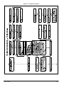
SEQUENCE OF OPERATION . . . . . . . . . . . . . . . . . . . . . . . . . . . . . 42
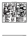
WIRING DIAGRAM . . . . . . . . . . . . . . . . . . . . . . . . . . . . . . . . . . . . . . 44
TROUBLESHOOTING GUIDE . . . . . . . . . . . . . . . . . . . . . . . . . . . . . 45
Use of the AHRI Certified TM Mark indicates a manufacturer’s participation in the
program. For verification of certification for
individual products, go to www.ahridirectory.org .
!
WARNING
PERSONAL INJURY, AND/OR PROPERTY
DAMAGE HAZARD
Failure to carefully read and follow this warning could
result in equipment malfunction, property damage,
personal injury and/or death.
Installation or repairs made by unqualified persons
could result in equipment malfunction, property
damage, personal injury and/or death.
The information contained in this manual is intended for
use by a qualified service technician familiar with safety
procedures and equipped with proper tools and test
instruments.
Installation must conform with local building codes and
with the Natural Fuel Gas Code (NFCG) NFPA
54/ANSI Z223.1
INSTALLER: Affix these instructions on or adjacent to the furnace.
CONSUMER: Retain these instructions for future reference.
Portions of the text and tables are reprinted from NFPA 54 /ANSI Z223.1−2012, with permission of National Fire Protection Association, Quincy, MA 02269 and American Gas Association, Washington, DC 20001. This reprinted material is not the complete and official position of the NFPA or ANSI, on the referenced subject, which is represented only by the standard in its entirety.
Printed in U.S.A.
441 01 1421 01 2/18/2015
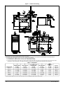
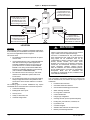
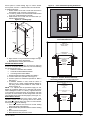
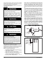
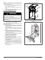
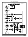
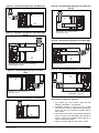
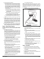
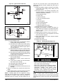
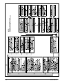
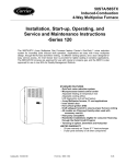
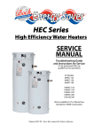
Figure 1 − Dimensional Drawing
NOTES:
1. Two additional 7/8−in. (22 mm) diameter holes are located in the top plate.
2. Minimum return−air openings at furnace, based on metal duct. If flex duct is used, see flex duct manufacturer’s recommendations for equivalent diameters.
a. For 800 CFM−16−in. (406 mm) round or 14 1/2 x 12−in. (368 x 305 mm) rectangle.
b. For 1200 CFM−20−in. (508 mm) round or 14 1/2 x 19 1/2−in. (368 x 495 mm) rectangle.
c. For 1600 CFM−22−in. (559 mm) round or 14 1/2 x 22 1/16−in. (368 x 560mm) rectangle.
d. For airflow requirements above 1800 CFM, see Air Delivery table in Product Data literature for specific use of single side inlets. The use of both side inlets, a
combination of 1 side and the bottom, or the bottom only will ensure adequate return air openings for airflow requirements above 1800 CFM.
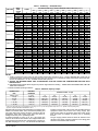
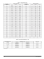
Table 1 – Dimensions
A
FURNACE SIZE
0451412
0701712
0701716
0901714
0902116
1102120
1352420
CABINET WIDTH
IN. (MM)
14−3/16 (360)
17−1/2 (445)
17−1/2 (445)
17−1/2 (445)
21 (533)
21 (533)
24−1/2 (622)
B
C
D
OUTLET WIDTH
IN. (MM)
12−9/16 (319)
15−7/8 (403)
15−7/8 (403)
15−7/8 (403)
19−3/8 (492)
19−3/8 (492)
22−7/8 (581)
TOP AND BOTTOM
FLUE COLLAR
IN. (MM)
9−5/16 (237)
11−9/16 (294)
11−9/16 (294)
11−9/16 (294)
13−5/16 (338)
13−5/16 (338)
15−1/16 (383)
BOTTOM WIDTH
IN. (MM)
12−11/16 (322)
16 (406)
16 (406)
16 (406)
19−1/2 (495)
19−1/2 (495)
23 (584)
VENT
CONNECTION
SIZE*
IN. (MM)
4 (102)
4 (102)
4 (102)
4 (102)
4 (102)
4 (102)
4 (102)*
SHIP WT
(LB / KG)
104 (47)
126 (57)
126 (57)
127 (58)
140 (64)
152 (69)
163 (74)
* 135 size furnaces require a 5 in. or 6 in. (127 or 152 mm) vent. Use a vent adapter between furnace and vent stack.
2
Specifications are subject to change without notice.
441 01 1421 01
SAFETY CONSIDERATIONS
!
!
WARNING
CAUTION
CUT HAZARD
FIRE, EXPLOSION, ELECTRICAL SHOCK, AND
CARBON MONOXIDE POISONING HAZARD
Failure to follow this caution may result in personal
injury.
Failure to follow this warning could result in dangerous
operation, serious injury, death, or property damage.
Sheet metal parts may have sharp edges or burrs.
Use care and wear appropriate protective clothing,
safety glasses and gloves when handling parts and
servicing furnaces.
1. Use only with type of gas approved for this furnace.
Refer to the furnace rating plate.
2. Install this furnace only in a location and position as
specified in the “Location” section of these instructions.
3. Provide adequate combustion and ventilation air to the
furnace space as specified in “Air for Combustion and
Ventilation” section.
4. Combustion products must be discharged outdoors.
Connect this furnace to an approved vent system only,
as specified in the “Venting” section of these instructions.
5. Never test for gas leaks with an open flame. Use a
commercially available soap solution made specifically
for the detection of leaks to check all connections, as
specified in the “Gas Piping” section.
6. Always install furnace to operate within the furnace’s
intended temperature−rise range with a duct system
which has an external static pressure within the allowable range, as specified in the “Start−Up, Adjustments,
and Safety Check” section. See furnace rating plate.
7. When a furnace is installed so that supply ducts carry
air circulated by the furnace to areas outside the space
containing the furnace, the return air shall also be
handled by duct(s) sealed to the furnace casing and
terminating outside the space containing the furnace.
See “Air Ducts” section.
8. A gas−fired furnace for installation in a residential garage must be installed as specified in the warning box in
the “Location” section.
9. The furnace may be used for construction heat
provided that the furnace installation and operation
complies with the first CAUTION in the LOCATION section of these instructions.
10. These Multipoise Gas−Fired Furnaces are CSA
(formerly A.G.A. and C.G.A). design−certified for use
with natural and propane gases (see furnace rating
plate) and for installation in alcoves, attics, basements,
closets, utility rooms, crawlspaces, and garages. The
furnace is factory−shipped for use with natural gas. A
CSA listed accessory gas conversion kit is required to
convert furnace for use with propane gas.
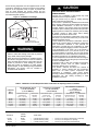
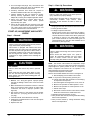
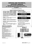
11. See Figure 2 for required clearances to combustible
construction.
12. Maintain a 1−in. (25 mm) clearance from combustible
materials to supply air ductwork for a distance of 36
inches (914 mm) horizontally from the furnace. See
NFPA 90B or local code for further requirements.
13. These furnaces SHALL NOT be installed directly on
carpeting, tile, or any other combustible material other
than wood flooring. In downflow installations, factory
accessory floor base MUST be used when installed on
combustible materials and wood flooring. Special base
is not required when this furnace is installed on manufacturer’s coil model numbers END4X, ENW4X or coil
casing model number NAEA. See Figure 2 for clearance to combustible construction information.
Improper installation, adjustment, alteration, service,
maintenance, or use could cause carbon monoxide
poisoning, explosion, fire, electrical shock, or other
conditions which may cause personal injury or property
damage. Consult a qualified service agency, local gas
supplier, or your distributor or branch for information or
assistance. The qualified service agency must use only
factory−authorized and listed kits or accessories when
modifying this product.
!
CAUTION
FURNACE RELIABILITY HAZARD
Improper installation or misapplication of furnace may
require excessive servicing or cause premature
component failure.
Application of this furnace should be indoors with
special attention given to vent sizing and material,
gas input rate, air temperature rise, unit leveling, and
unit sizing.
Improper installation, adjustment, alteration, service,
maintenance, or use can cause explosion, fire, electrical
shock, or other conditions which may cause death, personal
injury, or property damage. Consult a qualified installer,
service agency, or your distributor or branch for information or
assistance. The qualified installer or agency must use
factory−authorized kits or accessories when modifying this
product. Refer to the individual instructions packaged with
the kits or accessories when installing.
Follow all safety codes. Wear safety glasses, protective
clothing, and work gloves. Have a fire extinguisher available.
Read these instructions thoroughly and follow all warnings or
cautions include in literature and attached to the unit. Consult
local building codes, the current editions of the National Fuel
Gas Code (NFGC) NFPA 54/ANSI Z223.1 and the National
Electrical Code (NEC) NFPA 70.
Recognize safety information. This is the safety−alert symbol
. When you see this symbol on the unit and in instructions
or manuals, be alert to the potential for personal injury.
Understand the signal words DANGER, WARNING, and
CAUTION. These words are used with the safety−alert
symbol. DANGER identifies the most serious hazards which
will result in severe personal injury or death. WARNING
signifies hazards which could result in personal injury or
death. CAUTION is used to identify unsafe practices which
may result in minor personal injury or product and property
damage. NOTE is used to highlight suggestions which will
result in enhanced installation, reliability, or operation.
441 01 1421 01
Specifications are subject to change without notice.
3
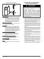
INTRODUCTION
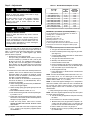
(16_C)db or intermittent operation down to 55_F (13_C) db
such as when used with a night setback thermostat.
Return−air temperature must not exceed 80_F (27_C) db.
Failure to follow these return−air temperature limits may affect
reliability of heat exchangers, motors, and controls. (See
Figure 3).
For accessory installation details, refer to the applicable
instruction literature.
NOTE: Remove all shipping brackets and materials before
operating the furnace.
N8MXN 4−way multipoise Category I fan−assisted furnace is
CSA design−certified. A Category I fan−assisted furnace is
an appliance equipped with an integral mechanical means to
either draw or force products of combustion through the
combustion chamber and/or heat exchanger. The furnace is
factory−shipped for use with natural gas.
This furnace is not approved for installation in mobile homes,
recreational vehicles, or outdoors. This furnace is designed
for minimum continuous return−air temperature of 60_F
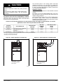
Figure 2 − Clearances to Combustibles
CODES AND STANDARDS
Follow all national and local codes and standards in addition
to these instructions. The installation must comply with
regulations of the serving gas supplier, local building, heating,
plumbing, and other codes. In absence of local codes, the
installation must comply with the national codes listed below
and all authorities having jurisdiction.
4
In the United States, follow all codes and standards for the
following:
Safety
S
USA: National Fuel Gas Code (NFGC) NFPA
54−2012/ANSI Z223.1−2012 and the Installation
Standards, Warm Air Heating and Air Conditioning
Systems ANSI/NFPA 90B
Specifications are subject to change without notice.
441 01 1421 01
ELECTROSTATIC DISCHARGE (ESD)
PRECAUTIONS PROCEDURE
Figure 3 − Return Air Temperature
!
80_F/27_C
CAUTION
FURNACE RELIABILITY HAZARD
Improper installation or service of furnace may cause
premature furnace component failure.
60_F/16_C
A06745
General Installation
S
Current edition of the NFGC and the NFPA 90B. For
copies, contact the National Fire Protection Association Inc., Batterymarch Park, Quincy, MA 02269;
(www.NFPA.org) or for only the NFGC, contact the
American Gas Association, 400 N. Capitol Street,
N.W., Washington, DC 20001 (www.AGA.org).
Combustion and Ventilation Air
S
NFGC NFPA 54/ANSI Z223.1−2012 Section 9.3, Air
for Combustion and Ventilation.
Duct Systems
S
Air Conditioning Contractors Association (ACCA)
Manual D, Sheet Metal and Air Conditioning Contractors National Association (SMACNA), or American Society of Heating, Refrigeration, and Air Conditioning Engineers (ASHRAE) 2005 Fundamentals
Handbook Chapter 35 or 2004 HVAC Systems and
Equipment Handbook Chapters 9 and 16.
Acoustical Lining and Fibrous Glass Duct
S
Current edition of SMACNA and NFPA 90B as
tested by UL Standard 181 for Class I Rigid Air
Ducts
Gas Piping and Gas Pipe Pressure Testing
S
NFGC NFPA 54/ANSI Z223.1−2012; chapters 5, 6,
7, and 8 and National Plumbing Codes.
Electrical Connections
S
National Electrical Code (NEC) NFPA 70−2011.
Venting
S
NFGC NFPA 54 / ANSI Z223.1−2012; Chapters 12
and 13.
441 01 1421 01
Electrostatic
discharge
can
affect
electronic
components. Follow the Electrostatic Discharge
Precautions Procedure listed below during furnace
installation and servicing to protect the furnace
electronic control. Precautions will prevent electrostatic
discharges from personnel and hand tools which are
held during the procedure. These precautions will help
to avoid exposing the control to electrostatic discharge
by putting the furnace, the control, and the person at the
same electrostatic potential.
1. Disconnect all power to the furnace. Multiple disconnects may be required. DO NOT TOUCH THE
CONTROL OR ANY WIRE CONNECTED TO THE
CONTROL PRIOR TO DISCHARGING YOUR BODY’S
ELECTROSTATIC CHARGE TO GROUND.
2. Firmly touch the clean, unpainted, metal surface of the
furnace chassis which is close to the control. Firmly
touch the clean, unpainted, metal surface of the furnace chassis which is close to the control. Tools held in
a person’s hand during grounding will be satisfactorily
discharged.
3. After touching the chassis, you may proceed to service
the control or connecting wires as long as you do nothing to recharge your body with static electricity (for example; DO NOT move or shuffle your feet, do not touch
ungrounded objects, etc.).
4. If you touch ungrounded objects (and recharge your
body with static electricity), firmly touch a clean, unpainted metal surface of the furnace again before
touching control or wires.
5. Use this procedure for installed and uninstalled (ungrounded) furnaces.
6. Before removing a new control from its container, discharge your body’s electrostatic charge to ground to
protect the control from damage. If the control is to be
installed in a furnace, follow items 1 through 4 before
bringing the control or yourself in contact with the furnace. Put all used and new controls into containers before touching ungrounded objects.
7. An ESD service kit (available from commercial
sources) may also be used to prevent ESD damage.
Specifications are subject to change without notice.
5
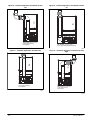
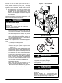
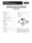
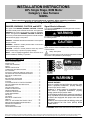
Figure 4 − Multipoise Orientations
THE BLOWER IS
LOCATED BELOW THE
BURNER SECTION, AND
CONDITIONED AIR IS
DISCHARGED UPWARD.
THE BLOWER IS LOCATED
TO THE RIGHT OF THE
BURNER SECTION, AND
AIR CONDITIONED AIR IS
DISCHARGED TO THE LEFT.
THE BLOWER IS
LOCATED TO THE LEFT
OF THE BURNER SECTION,
AND CONDITIONED AIR IS
DISCHARGED TO THE RIGHT.
THE BLOWER IS
LOCATED ABOVE THE
BURNER SECTION, AND
CONDITIONED AIR IS
DISCHARGED DOWNWARD
A02097
LOCATION
GENERAL
This multipoise furnace is shipped in packaged configuration.
Some assembly and modifications are required when used in
any of the four applications shown in Figure 4.
This furnace must:
S
be installed so the electrical components are protected from water.
S
not be installed directly on any combustible material
other than wood flooring for upflow applications.
Downflow installations require use of a factory−approved floor base or coil model numbers END4X,
ENW4X or coil casing model number NAEA when
installed on combustible materials or wood flooring
(refer to SAFETY CONSIDERATIONS).
S
be located as close to the chimney or vent and attached to an air distribution system. Refer to Air
Ducts section.
S
be provided ample space for servicing and cleaning.
Always comply with minimum fire protection clearances shown on the furnace clearance to combustible label.
The following types of furnace installations may require
OUTDOOR AIR for combustion due to chemical exposures:
S
S
S
S
S
6
Commercial buildings
Buildings with indoor pools
Laundry rooms
Hobby or craft rooms, and
Chemical storage areas
!
WARNING
CARBON MONOXIDE POISONING HAZARD
Failure to follow this warning could result in personal
injury or death, and unit component damage.
Corrosive or contaminated air may cause failure of
parts containing flue gas, which could leak into the
living space. Air for combustion must not be
contaminated by halogen compounds, which include
fluoride, chloride, bromide, and iodide. These
elements can corrode heat exchangers and shorten
furnace life. Air contaminants are found in aerosol
sprays, detergents, bleaches, cleaning solvents,
salts, air fresheners, and other household products.
Do not install furnace in a corrosive or contaminated
atmosphere. Make sure all combustion and
circulating air requirements are met, in addition to all
local codes and ordinances.
If air is exposed to the following substances, it should not be
used for combustion air, and outdoor air may be required for
combustion:
S
S
S
S
S
S
S
S
S
S
S
S
S
Permanent wave solutions
Chlorinated waxes and cleaners
Chlorine based swimming pool chemicals
Water softening chemicals
De−icing salts or chemicals
Carbon tetrachloride
Halogen type refrigerants
Cleaning solvents (such as perchloroethylene)
Printing inks, paint removers, varnishes, etc.
Hydrochloric acid
Cements and glues
Antistatic fabric softeners for clothes dryers
Masonry acid washing materials
Specifications are subject to change without notice.
441 01 1421 01
All fuel−burning equipment must be supplied with air for fuel
combustion. Sufficient air must be provided to avoid negative
pressure in the equipment room or space. A positive seal
must be made between the furnace cabinet and the
return−air duct to prevent pulling air from the burner area and
from draft safeguard opening.
Figure 5 − Installation in a Garage
!
PERSONAL INJURY AND/OR PROPERTY
DAMAGE HAZARD
Improper use or installation of this furnace may cause
premature furnace component failure.
This gas furnace may be used for heating buildings
under construction provided that:
−The furnace is permanently installed with all electrical
wiring, piping, venting and ducting installed according to
these installation instructions. A return air duct is
provided, sealed to the furnace casing, and terminated
outside the space containing the furnace. This prevents a
negative pressure condition as created by the circulating
air blower, causing a flame rollout and/or drawing
combustion products into the structure.
−The furnace is controlled by a thermostat. It may not be
“hot wired” to provide heat continuously to the structure
without thermostatic control.
−Clean outside air is provided for combustion. This is to
minimize the corrosive effects of adhesives, sealers and
other construction materials. It also prevents the
entrainment of drywall dust into combustion air, which
can cause fouling and plugging of furnace components.
−The temperature of the return air to the furnace is
maintained between 55_F (13_C) and 80_F (27_C), with
no evening setback or shutdown. The use of the furnace
while the structure is under construction is deemed to be
intermittent operation per our installation instructions.
−The air temperature rise is within the rated rise range on
the furnace rating plate, and the gas input rate has been
set to the nameplate value.
−The filters used to clean the circulating air during the
construction process must be either changed or
thoroughly cleaned prior to occupancy.
−The furnace, ductwork and filters are cleaned as
necessary to remove drywall dust and construction
debris from all HVAC system components after
construction is completed. −Verify proper furnace
operating conditions including ignition, gas input rate, air
temperature rise, and venting according to these
installation instructions.
18−IN. (457.2 mm)
MINIMUM TO BURNERS
A93044
WARNING
!
CAUTION
FIRE HAZARD
Failure to follow this warning could result in personal
injury, death, and/or property damage.
When the furnace is installed in a residential garage,
the burners and ignition sources must be located at
least 18 inches above the floor. The furnace must be
located or protected to avoid damage by vehicles.
When the furnace is installed in a public garage,
airplane hangar, or other building having a hazardous
atmosphere, the furnace must be installed in
accordance with the NFGC.
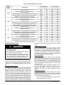
Table 2 – Minimum Free Area Required for Each Combustion Air Opening or Duct to Outdoors
TWO HORIZONTAL DUCTS
(1 SQ. IN./2,000 BTUH)
(1,100 SQ. MM/KW)
FURNACE
INPUT
(BTUH)
Free Area of Opening and Duct
(sq. in. / sq. mm)
22 (14193)
33 (21290)
44 (28387)
55 (35484)
66 (42581)
44,000
66,000
88,000
110,000
132,000
Round Duct
Diameter
(in./mm)
6 (152)
7 (178)
8 (203)
9 (229)
10 (254)
SINGLE DUCT OR OPENING
(1 SQ. IN./3,000 BTUH)
(734 SQ. MM/KW)
Free Area of Opening and Duct
(sq. In. / sq. mm)
14.7 (9484)
22 (14193)
29.3 (18903)
36.7 (23677)
44 (28387)
Round Duct
Diameter
(in. / mm)
5 (127)
6 (152)
7 (178)
7 (178)
8 (203)
TWO OPENINGS OR VERTICAL
DUCTS
(1 SQ. IN./4,000 BTUH)
(550 SQ. MM/KW)
Free Area of
Round Duct
Opening and Duct
Diameter
(sq. In. / sq. mm)
(In./mm)
11 (7097)
4 (102)
16.5 (10645)
5 (127)
22 (14193)
6 (152)
27.5 (17742)
6 (152)
33 (21290)
7 (178)
EXAMPLES: Determining Free Area
WATER
HEATER
FURNACE
110,000
+
66,000
+
40,000
=
(106,000 divided by 3,000)
=
35.3 Sq. In. for a Single Duct or Opening
88,000
+
30,000
=
(118,000 divided by 2,000)
=
59.0 Sq. In. for each of two Horizontal Ducts
441 01 1421 01
30,000
TOTAL INPUT
=
(140,000 divided by 4,000)
=
35.0 Sq. In. for each two Vertical Ducts or Openings
Specifications are subject to change without notice.
7
Table 3 – Minimum Space volumes for 100% combustion, Ventilation, and Dilution from Indoors
OTHER THAN FAN−ASSISTED TOTAL
(1,000’S BTUH GAS INPUT RATE
ACH
30
40
FAN−ASSISTED TOTAL
(1,000’S BTUH GAS INPUT RATE)
50
44
66
88
110
132
Space Volume (ft.3)
0.60
1,050
1,400
1,750
1,100
1,650
2,200
2,750
3,300
0.50
1,260
1,680
2,100
1,320
1,980
2,640
3,300
3,960
0.40
1,575
2,100
2,625
1,650
2,475
3,300
4,125
4,950
0.30
2,100
2,800
3,500
2,200
3,300
4,400
5,500
6,600
0.20
3,150
4,200
5,250
3,300
4,950
6,600
8,250
9,900
0.10
6,300
8,400
10,500
6,600
9,900
13,200
16,500
19,800
0.00
NP
NP
NP
NP
NP
NP
NP
NP
ACH = Air Changes/Hour
NP = Not Permitted
!
FIRE HAZARD
AIR FOR COMBUSTION AND
VENTILATION
WARNING
Failure to follow this warning could result in personal
injury, death and/or property damage.
Do not install the furnace on its back or hang furnace
with control compartment facing downward. Safety
control operation will be adversely affected. Never
connect return−air ducts to the back of the furnace.
(See Figure 6)
Figure 6 − Prohibit Installation on Back
Provisions for adequate combustion, ventilation, and dilution
air must be provided in accordance with:
S
U.S. installations: Section 9.3 of the NFGC NFPA
54/ANSI Z223.1−2012, Air for Combustion and Ventilation, and applicable provisions of the local building
codes.
!
WARNING
CARBON MONOXIDE POISONING HAZARD
Failure to follow this warning could result in personal
injury or death.
The operation of exhaust fans, kitchen ventilation
fans, clothes dryers, attic exhaust fans or fireplaces
could create a NEGATIVE PRESSURE CONDITION
at the furnace. Make−up air MUST be provided for the
ventilation devices, in addition to that required by the
furnace. Refer to Carbon Monoxide Poisoning Hazard
warning in venting section of these instructions to
determine if an adequate amount of make−up air is
available.
A02054
!
CAUTION
The requirements for combustion and ventilation air depend
upon whether or not the furnace is located in a space having
a volume of at least 50 cubic feet per 1,000 Btuh input rating
for all gas appliances installed in the space.
S
FURNACE CORROSION HAZARD
Failure to follow this caution may result in furnace
damage.
Air for combustion must not be contaminated by
halogen compounds, which include fluoride, chloride,
bromide, and iodide. These elements can corrode
heat exchangers and shorten furnace life. Air
contaminants are found in aerosol sprays,
detergents, bleaches, cleaning solvents, salts, air
fresheners, and other household products.
LOCATION RELATIVE TO COOLING EQUIPMENT
The cooling coil must be installed parallel with, or on the
downstream side of the unit to avoid condensation in the heat
exchangers. When installed parallel with the furnace,
dampers or other flow control must prevent chilled air from
entering the furnace. If the dampers are manually operated,
they must be equipped with means to prevent operation of
either unit unless the damper is in the full−heat or full−cool
position.
8
Spaces having less than 50 cubic feet per 1,000
Btuh require the OUTDOOR COMBUSTION AIR
METHOD.
S
Spaces having at least 50 cubic feet per 1,000 Btuh
may use the INDOOR COMBUSTION AIR,
STANDARD or KNOWN AIR INFILTRATION
METHOD.
Outdoor Combustion Air Method
1. Provide the space with sufficient air for proper combustion, ventilation, and dilution of flue gases using permanent horizontal or vertical duct(s) or opening(s) directly communicating with the outdoors or spaces that
freely communicate with the outdoors.
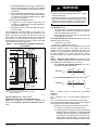
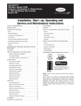
2. Figure 7 illustrates how to provide TWO OUTDOOR
OPENINGS, one inlet and one outlet combustion and
ventilation air opening, to the outdoors.
a. One opening MUST commence within 12−in. (300
mm) of the ceiling and the second opening MUST
commence within 12−in. (300 mm) of the floor.
b. Size openings and ducts per Figure 7 and Table 2.
Specifications are subject to change without notice.
441 01 1421 01
c. TWO HORIZONTAL DUCTS require 1 square inch of
free area per 2,000 Btuh (1,100 mm2/kW) of combined
input for all gas appliances in the space per Figure 7
and Table 2.
d. TWO OPENINGS OR VERTICAL DUCTS require 1
square inch of free area per 4,000 Btuh (550 mm2/kW)
for combined input of all gas appliances in the space
per Figure 7 and Table 2.
3. ONE OUTDOOR OPENING requires:
a. 1 square inch of free area per 3,000 Btuh (734
mm2/kW) for combined input of all gas appliances in
the space per Table 2 and
b. Not less than the sum of the areas of all vent connectors in the space.
The opening shall commence within 12” (300 mm) of the
ceiling. Appliances in the space shall have clearances of at
least 1” (25 mm) from the sides and back and 6” (150 mm)
from the front. The opening shall directly communicate with
the outdoors or shall communicate through a vertical or
horizontal duct to the outdoors or spaces (crawl or attic) that
freely communicate with the outdoors.
Figure 7 − Air for Combustion, Ventilation, and Dilution
from Outdoors
1 SQ IN.
PER 4000
BTUH*
DUCTS
TO
OUTDOORS
1 SQ IN.
PER 2000
BTUH*
(305mm) 12″ MAX
A
12″ (305mm)
MAX
D
VENT
THROUGH
ROOF
F
1 SQ IN.
PER
4000
BTUH*
OUTDOORS
B
CLEARANCE IN FRONT
OF COMBUSTION AIR
OPENINGS SHALL BE
AT LEAST 3 IN.
(76mm)
(305mm) 12″ MAX
1 SQ IN.
PER 2000
BTUH*
CIRCULATING
AIR DUCTS
DUCTS
TO
OUTDOORS
Many homes require air to be supplied from outdoors
for furnace combustion, ventilation, and dilution of flue
gases. The furnace combustion air supply must be
provided in accordance with this instruction manual.
The Standard Method:
1. The space has no less volume than 50 cubic feet per
1,000 Btuh of the maximum input ratings for all gas appliances installed in the space and
2. The air infiltration rate is not known to be less than 0.40
air changes per hour (ACH).
The Known Air Infiltration Rate Method shall be used, if the
infiltration rate is known to be:
1. Less than 0.40 ACH and
2. Equal to or greater than 0.10 ACH
Infiltration rates greater than 0.60 ACH shall not be used. The
minimum required volume of the space varies with the
number of ACH and shall be determined per Table 3 or
Equations 1 and 2. Determine the minimum required volume
for each appliance in the space and add the volumes
together to get the total minimum required volume for the
space.
Table 3 − Minimum Space Volumes were determined by
using the following equations from the National Fuel Gas
Code ANSI Z223.1−2012/NFPA 54−2012, 9.3.2.2:
1. For other than fan−assisted appliances, such as a
draft hood−equipped water heater:
12″ (305mm)
MAX
C
DUCT
TO
OUTDOORS
3
I other
= 21ft
Other
ACH 1000 Btu/hr
A04002
G
2. For fan−assisted appliances such as this furnace:
Volume
1 SQ IN.
PER 4000
BTUH*
Fan
3
I fan
= 15ft
ACH 1000 Btu/hr
A004003
*Minimum dimensions of 3 in. (76 mm).
NOTE: Use any of the following combinations of openings:
A&B, C&D, D&E, F&G
A03174
Indoor Combustion Air − NFPA & AGA
Standard and Known−Air−Infiltration Rate Methods
Indoor air is permitted for combustion, ventilation, and
dilution, if the Standard or Known−Air−Infiltration Method is
used.
441 01 1421 01
Failure to follow this warning could result in death
and/or personal injury.
1 SQ IN.
PER
4000
BTUH*
E
WARNING
CARBON MONOXIDE POISONING HAZARD
Volume
12″ MAX
(305mm)
CIRCULATING AIR DUCTS
!
If:
Iother = combined input of all other than fan−assisted
appliances
in Btuh/hr
Ifan = combined input of all fan−assisted appliances in
Btuh/hr
ACH = air changes per hour (ACH shall not exceed 0.60.)
The following requirements apply to the Standard Method
and to the Known Air Infiltration Rate Method.
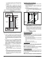
1. Adjoining rooms can be considered part of a space if:
a. There are no closeable doors between rooms.
b. Combining spaces on same floor level. Each opening
shall have free area of at least 1 in.2/1,000 Btuh (2,000
mm2/kW) of the total input rating of all gas appliances
in the space, but not less than 100 in.2 (0.06 m2). One
opening shall commence within 12” (300 mm) of the
ceiling and the second opening shall commence with-
Specifications are subject to change without notice.
9
in 12” (300 mm) of the floor. The minimum dimension
of air openings shall be at least 3 in. (80 mm). (See
Figure 8)
c. Combining space on different floor levels. The
volumes of spaces on different floor levels shall be
considered as communicating spaces if connected by
one or more permanent openings in doors or floors
having free area of at least 2 in.2/1,000 Btuh (4,400
mm2/kW) of total input rating of all gas appliances.
Figure 8 − Air for Combustion, Ventilation, and Dilution
from Indoors
VENT THROUGH ROOF
CLEARANCE IN FRONT OF COMBUSTION AIR
OPENINGS SHALL BE AT LEAST 3 IN.
CIRCULATING AIR
DUCTS
INTERIOR
HEATED
SPACE
Combination of Indoor and Outdoor Air
1. Indoor openings shall comply with the Indoor Combustion Air Method below and,
2. Outdoor openings shall be located as required in the
Outdoor Combustion Air Method mentioned previously and,
3. Outdoor openings shall be sized as follows:
a. Calculate the Ratio of all Indoor Space volume divided
by required volume for Indoor Combustion Air Method below.
Figure 9 − Removing Bottom Closure Panel
12" MAX (305mm)
1 SQ IN.
PER 1000
BTUH* IN DOOR
OR WALL
UNCONFINED
SPACE
BOTTOM
CLOSURE
PANEL
6" MIN (152mm)
(FRONT)Ü
BOTTOM
FILLER PANEL
1 SQ IN.
PER 1000
BTUH* IN DOOR
OR WALL
12" MAX (305mm)
CIRCULATING AIR DUCTS
b. Outdoor opening size reduction Factor is 1 minus the
Ratio in a. above.
c. Minimum size of Outdoor openings shall be the size
required in Outdoor Combustion Air Method above
multiplied by reduction Factor in b. above. The minimum dimension of air openings shall be not less than
3 in. (80 mm).
INSTALLATION
in.2 with
*Minimum opening size is 100
minimum dimensions of 3 in. (76 mm).
*Minimum of 3 in. (76 mm), when type −B1 vent is used.
A03175
2. An attic or crawlspace may be considered a space that
freely communicates with the outdoors provided there
are adequate permanent ventilation openings directly
to outdoors having free area of at least 1−in.2/4,000
Btuh of total input rating for all gas appliances in the
space.
3. In spaces that use the Indoor Combustion Air Method, infiltration should be adequate to provide air for
combustion, permanent ventilation and dilution of flue
gases. However, in buildings with unusually tight construction, additional air MUST be provided using the
methods described in the Outdoor Combustion Air
Method section.
Unusually tight construction is defined as construction with:
a. Walls and ceilings exposed to the outdoors have a
continuous, sealed vapor barrier. Openings are gasketed or sealed and
b. Doors and openable windows are weatherstripped
and
c. Other openings are caulked or sealed. These include
joints around window and door frames, between sole
plates and floors, between wall−ceiling joints, between
wall panels, at penetrations for plumbing, electrical
and gas lines, etc.
10
UPFLOW INSTALLATION
Bottom Return Air Inlet
These furnaces are shipped with bottom closure panel
installed in bottom return−air opening. Remove and discard
this panel when bottom return air is used. To remove bottom
closure panel, perform the following:
1. Tilt or raise furnace and remove two screws holding
bottom filler panel. (See Figure 9)
2. Rotate bottom filler panel downward to release holding
tabs.
3. Remove bottom closure panel.
4. Reinstall bottom filler panel and screws.
Side Return Air Inlet
These furnaces are shipped with bottom closure panel
installed in bottom return−air opening. This panel MUST be in
place when only side return air is used.
NOTE: Side return−air openings can be used in UPFLOW
and most HORIZONTAL configurations. Do not use side
return−air openings in DOWNFLOW configuration.
Leveling Legs (If Desired)
In upflow position with side return inlet(s), leveling legs may
be used. (See Figure 10) Install field−supplied, 5/16 x 1−1/2
in. (8 x 38 mm) (max) corrosion−resistant machine bolts,
washers and nuts.
NOTE: Bottom closure must be used when leveling legs are
used. It may be necessary to remove and reinstall bottom
Specifications are subject to change without notice.
441 01 1421 01
closure panel to install leveling legs. To remove bottom
closure panel, see Item 1. in Bottom Return Air Inlet section.
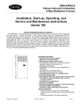
To install leveling legs:
1. Position furnace on its back. Locate and drill a hole in
each bottom corner of furnace. (See Figure 10)
2. For each leg, install nut on bolt and then install bolt and
nut in hole. (Install flat washer if desired.)
3. Install another nut on other side of furnace base. (Install flat washer if desired.)
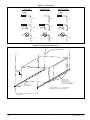
Figure 10 − Leveling Legs
Figure 11 − Floor and Plenum Opening Dimensions
A
B
5/ 16
D
(8mm)
(8mm)
5/ 16
C
3/4
1
(44mm)
A96283
1 3/4
(44mm)
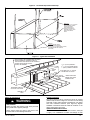
Figure 12 − Furnace, Plenum, and Subbase Installed
on a Combustible Floor
(8mm)
5/16
FURNACE
(OR COIL CASING
WHEN USED)
(8mm)
5/ 16
(44mm) 1 3/ 4
3/
(44mm) 1 4
COMBUSTIBLE
FLOORING
A89014
4. Adjust outside nut to provide desired height, and tighten inside nut to secure arrangement.
5. Reinstall bottom closure panel if removed.
DOWNFLOW INSTALLATION
NOTE: For downflow applications, this furnace is approved
for use on combustible flooring when any one of the following
two accessories are used:
S Downflow combustible floor subbase
S Coil model numbers END4X, ENW4X
S Coil casing model number NAEA
1. Determine application being installed from Table 4.
2. Construct hole in floor per Table 4 and Figure 11.
3. Construct plenum to dimensions specified in Table 4
and Figure 11.
4. If downflow subbase is used, install as shown in
Figure 12. If coil model numbers END4X, ENW4X or
coil casing model number NAEA are used, install as
shown in Figure 13.
NOTE: It is required that the perforated supply−air duct
flanges be completely folded over or removed from furnace
when installing the furnace on a factory−supplied cased coil
or coil casing. To remove the supply−air duct flange, use wide
duct pliers or hand seamers to bend flange back and forth
until it breaks off. Be careful of sharp edges. (See Figure 14)
Bottom Return Air Inlet
These furnaces are shipped with bottom closure panel
installed in bottom return−air opening. Remove and discard
this panel when bottom return air is used. To remove bottom
closure panel, perform the following:
1. Tilt or raise furnace and remove two screws holding
bottom filler panel. (See Figure 9)
2. Rotate bottom filler panel downward to release holding
tabs.
3. Remove bottom closure panel.
4. Reinstall bottom filler panel and screws
441 01 1421 01
DOWNFLOW
SUBBASE
SHEET METAL
PLENUM
FLOOR
OPENING
A96285
Figure 13 − Furnace, Plenum, and Coil or
Coil Casing Installed on a Combustible Floor
Specifications are subject to change without notice.
FURNACE
APPROVED
COIL ASSEMBLY
OR
COIL BOX
COMBUSTIBLE
FLOORING
SHEET METAL
PLENUM
FLOOR
OPENING
A08556
11
Table 4 – Opening Dimensions − In. (mm)
FURNACE
CASING
WIDTH
PLENUM OPENING
APPLICATION
Upflow Applications on Combustible or Noncombustible Flooring
(subbase not required)
Downflow Applications on Noncombustible Flooring
(subbase not required)
14–3/16
(360)
Downflow Applications on Combustible Flooring (subbase required)
Downflow Applications on Combustible Flooring with Coil END4X,
ENW4X or Coil Casing NAEA (subbase not required)
Upflow Applications on Combustible or Noncombustible Flooring
(subbase not required)
Downflow Applications on Noncombustible Flooring
(subbase not required)
17–1/2
(445)
Downflow Applications on Combustible Flooring (subbase required)
Downflow Applications on Combustible Flooring Coil with Coil
END4X, ENW4X or Coil Casing NAEA (subbase not required)
Upflow Applications on Combustible or Noncombustible Flooring
(subbase not required)
Downflow Applications on Noncombustible Flooring
(subbase not required)
21
(533)
Downflow Applications on Combustible Flooring (subbase required)
Downflow Applications on Combustible Flooring with Coil END4X,
ENW4X or Coil Casing NAEA (subbase not required)
Upflow Applications on Combustible or Noncombustible Flooring
(subbase not required)
Downflow Applications on Noncombustible Flooring
(subbase not required)
24−1/2
(622)
Downflow Applications on Combustible Flooring (subbase required)
Downflow Applications on Combustible Flooring with Coil END4X,
ENW4X or Coil Casing NAEA (subbase not required)
HORIZONTAL INSTALLATION
!
WARNING
FIRE, EXPLOSION, AND CARBON MONOXIDE
POISONING HAZARD
Failure to follow this warning could result in personal
injury, death, and/or property damage.
Do not install the furnace on its back or hang furnace
with control compartment facing downward. Safety
control operation will be adversely affected. Never
connect return−air ducts to the back of the furnace.
The furnace can be installed horizontally in an attic or crawl
space on either the left−hand (LH) or right−hand (RH) side.
The furnace can be hung from floor joists, rafters or trusses or
installed on a non−combustible platform, blocks, bricks or
pad.
Suspended Furnace Support
The furnace may be supported under each end with threaded
rod, angle iron or metal plumber’s strap as shown. (See
Figure 15 and Figure 16) Secure angle iron to bottom of
furnace as shown. Heavy−gauge sheet metal straps
(plumber’s straps) may be used to suspend the furnace from
each bottom corner. To prevent screws from pulling out, use 2
#8 x 3/4−in. (19 mm) screws into the side and 2 #8 x 3/4−in.
(19 mm) screws in the bottom of the furnace casing for each
strap. (See Figure 15 and Figure 16) If the screws are
attached to ONLY the furnace sides and not the bottom, the
straps must be vertical against the furnace sides and not pull
away from the furnace sides, so that the strap attachment
12
A
12−11/16
(322)
12−9/16
(319)
11−13/16
(284)
12−5/16
(313)
16
(406)
15−7/8
(403)
15−1/8
(384)
15−1/2
(394)
19−1/2
(495)
19−3/8
(492)
18−5/8
(473)
19
(483)
23
(584)
22−7/8
(581)
22−1/8
(562)
22−1/2
(572)
B
21−5/8
(549)
19
(483)
19
(483)
19
(483)
21−5/8
(549)
19
(483)
19
(483)
19
(483)
21−5/8
(549)
19
(483)
19
(483)
19
(483)
21−1/8
(537)
19
(483)
19
(483)
19
(483)
FLOOR OPENING
C
13−5/16
(338)
13−3/16
(335)
13−7/16
(341)
13−5/16
(338)
16−5/8
(422)
16−1/2
(419)
16−3/4
(425)
16−1/2
(419)
20−1/8
(511)
20
(508)
20−1/4
(514)
20
(508)
23−5/8
(600)
23−1/2
(597)
23−3/4
(603)
23−1/2
(597)
D
22−1/4
(565)
19−5/8
(498)
20−5/8
(600)
20
(508)
22−1/4
(565)
19−5/8
(498)
20−5/8
(600)
20
(508)
22−1/4
(565)
19−5/8
(498)
20−5/8
(600)
20
(508)
22−1/4
(565)
19−5/8
(498)
20−5/8
(600)
20
(508)
screws are not in tension (are loaded in shear) for reliable
support.
Platform Furnace Support
Construct working platform at location where all required
furnace clearances are met. (See Figure 2 and Figure 17) For
furnaces with 1−in. (25 mm) clearance requirement on side,
set furnace on noncombustible blocks, bricks or angle iron.
For crawl space installations, if the furnace is not suspended
from the floor joists, the ground underneath furnace must be
level and the furnace set on blocks or bricks.
Roll−Out Protection
Provide a minimum 17−3/4 in. x 22 in. (451 mm x 559 mm)
piece of sheet metal for flame roll−out protection in front of
burner area for furnaces closer than 12 inches (305 mm)
above the combustible deck or suspended furnaces closer
than 12 inches (305 mm) to joists. The sheet metal MUST
extend underneath the furnace casing by 1 in. (25 mm) with
the door removed.
The bottom closure panel on furnaces of widths 17−1/2 in.
(445 mm) and larger may be used for flame roll−out
protection when bottom of furnace is used for return air
connection. See Figure 17 for proper orientation of roll−out
shield.
Bottom Return Air Inlet
These furnaces are shipped with bottom closure panel
installed in bottom return−air opening. Remove and discard
this panel when bottom return air is used. To remove bottom
closure panel, perform the following:
1. Tilt or raise furnace and remove two screws holding
bottom filler panel. (See Figure 9)
Specifications are subject to change without notice.
441 01 1421 01
2. Rotate bottom filler panel downward to release holding
tabs.
3. Remove bottom closure panel.
4. Reinstall bottom filler panel and screws. Side Return
Air Inlet
Side Return Air Inlet
These furnaces are shipped with bottom closure panel
installed in bottom return−air opening. This panel MUST be in
place when side return air inlet(s) is used without a bottom
return air inlet.
Not all horizontal furnaces are approved for side return air
connections. (See Figure 20).
FILTER ARRANGEMENT
!
WARNING
CARBON MONOXIDE AND POISONING
HAZARD
Failure to follow this warning could result in personal
injury, or death.
Never operate a furnace without a filter or with filter
access door removed.
There are no provisions for an internal filter rack in these
furnaces.
A field−supplied accessory external filter is required.
Refer to the instructions supplied with the external filter rack
for assembly and installation options.
AIR DUCTS
General Requirements
The duct system should be designed and sized according to
accepted national standards such as those published by: Air
Conditioning Contractors Association (ACCA), Sheet Metal
and Air Conditioning Contractors National Association
(SMACNA) or American Society of Heating, Refrigerating and
Air Conditioning Engineers (ASHRAE) or consult The Air
Systems Design Guidelines reference tables available from
your local distributor. The duct system should be sized to
handle the required system design CFM at the design
external static pressure. The furnace airflow rates are
provided in Table 5 − AIR DELIVERY−CFM (With Filter).
When a furnace is installed so that the supply ducts carry air
circulated by the furnace to areas outside the space
containing the furnace, the return air shall also be handled by
duct(s) sealed to the furnace casing and terminating outside
the space containing the furnace.
Secure ductwork with proper fasteners for type of ductwork
used. Seal supply− and return−duct connections to furnace
with code approved tape or duct sealer.
441 01 1421 01
NOTE:
Flexible connections should be used between
ductwork and furnace to prevent transmission of vibration.
Ductwork passing through unconditioned space should be
insulated and sealed to enhance system performance. When
air conditioning is used, a vapor barrier is recommended.
Maintain a 1−in. (25 mm) clearance from combustible
materials to supply air ductwork for a distance of 36 in. (914
mm) horizontally from the furnace. See NFPA 90B or local
code for further requirements.
Ductwork Acoustical Treatment
NOTE: Metal duct systems that do not have a 90 degree
elbow and 10 ft. (3 M) of main duct to the first branch take−off
may require internal acoustical lining. As an alternative,
fibrous ductwork may be used if constructed and installed in
accordance with the latest edition of SMACNA construction
standard on fibrous glass ducts. Both acoustical lining and
fibrous ductwork shall comply with NFPA 90B as tested by UL
Standard 181 for Class 1 Rigid air ducts.
Supply Air Connections
For a furnace not equipped with a cooling coil, the outlet duct
shall be provided with a removable access panel. This
opening shall be accessible when the furnace is installed and
shall be of such a size that the heat exchanger can be
viewed for possible openings using light assistance or a
probe can be inserted for sampling the airstream. The cover
attachment shall prevent leaks.
Upflow and Horizontal Furnaces
Connect supply−air duct to flanges on furnace supply−air
outlet. Bend flange upward to 90_ with wide duct pliers. (See
Figure 14) The supply−air duct must be connected to ONLY
the furnace supply−outlet−air duct flanges or air conditioning
coil casing (when used). DO NOT cut main furnace casing
side to attach supply air duct, humidifier, or other accessories.
All accessories MUST be connected to duct external to
furnace main casing.
NOTE: For horizontal applications, the top−most flange may
be bent past 90 degrees to allow the evaporator coil to hang
on the flange temporarily while the remaining attachment and
sealing of the coil are performed.
Downflow Furnaces
Connect supply−air duct to supply−air outlet on furnace. Bend
flange inward past 90_ with wide duct pliers. (See Figure 14)
The supply−air duct must be connected to ONLY the furnace
supply outlet or air conditioning coil casing (when used).
When installed on combustible material, supply−air duct must
be connected to ONLY the accessory subbase or a factory
approved air conditioning coil casing. DO NOT cut main
furnace casing to attach supply side air duct, humidifier, or
other accessories. All accessories MUST be connected to
duct external to furnace casing.
Specifications are subject to change without notice.
13
Figure 14 − Duct Flanges
UPFLOW
DOWNFLOW
HORIZONTAL
90
90
YES
YES
120
MIN
YES
120
MIN
YES
YES
YES
120
MIN
NO
NO
NO
A02020
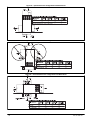
Figure 15 − Horizontal Unit Suspension
" (6mm) THREADED ROD
4 REQ.
1/4
OUTER DOOR
ASSEMBLY
SECURE ANGLE
IRON TO BOTTOM
OF FURNACE WITH
3 #8 x 3/4" (19mm) SCREWS
TYPICAL FOR 2 SUPPORTS
8" (203mm) MIN
FOR DOOR REMOVAL
1” (25mm) SQUARE, 1-1/4”x1-1/4”x1/8” (32x32x3mm)
ANGLE IRON OR UNI-STRUT MAY BE USED
(2) HEX NUTS, (2) WASHERS & (2) LOCK WASHERS
REQ. PER ROD
A10130
14
Specifications are subject to change without notice.
441 01 1421 01
Figure 16 − Horizontal Suspension with Straps
METHOD 2
USE (4) #8 x 3/4 (19 mm) SHEET
METAL SCREWS FOR EACH
STRAP. THE STRAPS
SHOULD BE VERTICAL
AGAINST THE FURNACE
SIDES AND NOT PULL AWAY
FROM THE FURNACE
SIDES.
METHOD 1
FOLD ALL STRAPS UNDER
FURNACE AND SECURE WTH
(4) #8 x 3/4 (19 mm) SHEET METAL SCREWS
(2 SCREWS IN SIDE AND 2 SCREWS
IN BOTTOM).
A10131
Figure 17 − Typical Attic Installation
LINE CONTACT ONLY PERMISSIBLE BETWEEN
LINES FORMED BY INTERSECTIONS OF
THE TOP AND TWO SIDES OF THE FURNACE
JACKET AND BUILDING JOISTS,
STUDS, OR FRAMING.
17 3/4″ (451mm)OVERALL
4 3/4″ (121mm) UNDER DOOR
1″ (25mm) UNDER FURNACE
GAS
ENTRY
TYPE-B
EXTEND OUT 12″ (305mm)
VENT
FROM FACE OF DOOR
)
m
52m
1
(
IN*
6″ M
30-IN. (762mm)
MIN WORK AREA * WHEN USED WITH
SINGLE WALL VENT
CONNECTIONS
17 3/4″ (451mm)
SHEET
METAL
559
22″ (
mm
)
EQUIPMENT MANUAL
SHUT-OFF GAS VALVE
SEDIMENT
TRAP
UNION
A10164
Return Air Connections
!
WARNING
FIRE HAZARD
Failure to follow this warning could cause personal
injury, death and/or property damage.
Never connect return−air ducts to the back of the
furnace. Refer to the following instructions.
441 01 1421 01
Downflow Furnaces
The return−air duct must be connected to return−air opening
(bottom inlet) as shown in Figure 21. DO NOT cut into casing
sides (left or right). Side opening is permitted for only upflow
and most horizontal furnaces. (See Figure 21) Bypass
humidifier connections should be made at ductwork or coil
casing sides exterior to furnace.
Upflow and Horizontal Furnaces
The return−air duct must be connected to bottom, sides (left
or right), or a combination of bottom and side(s) of main
Specifications are subject to change without notice.
15
furnace casing as shown in Figure 20 and Figure 22. Bypass
humidifier may be attached into unused return air side of the
furnace casing. (See Figure 20 and Figure 22)
Not all horizontal furnaces are approved for side return air
connections. (See Figure 22)
GAS PIPING
!
WARNING
FIRE OR EXPLOSION HAZARD
Failure to follow this warning could result in personal
injury, death, and/or property damage.
Never purge a gas line into a combustion chamber.
Never test for gas leaks with an open flame. Use a
commercially available soap solution made
specifically for the detection of leaks to check all
connections. A fire or explosion may result causing
property damage, personal injury or loss of life.
!
WARNING
FIRE OR EXPLOSION HAZARD
Failure to follow this warning could result in personal
injury,death, and/or property damage.
Use proper length of pipe to avoid stress on gas
control manifold and a gas leak.
!
Refer to Table 6 for recommended gas pipe sizing. Risers
must be used to connect to furnace and to meter. Support all
gas piping with appropriate straps, hangers, etc. Use a
minimum of 1 hanger every 6 ft. (2 M). Joint compound (pipe
dope) should be applied sparingly and only to male threads of
joints. Pipe dope must be resistant to the action of propane
gas.
An accessible manual equipment shutoff valve MUST be
installed external to furnace casing and within 6 ft. (2 M) of
furnace. A 1/8−in. (3 mm) NPT plugged tapping, accessible
for test gauge connection, MUST be installed immediately
upstream of gas supply connection to furnace and
downstream of manual equipment shutoff valve.
NOTE: The furnace gas control valve inlet pressure tap
connection is suitable to use as test gauge connection
providing test pressure DOES NOT exceed maximum 0.5
psig (14−in. w.c.) stated on gas control valve. (See Figure 41)
Some installations require gas entry on right side of furnace
(as viewed in upflow). (See Figure 18)
Install a sediment trap in riser leading to furnace as shown in
Figure 19. Connect a capped nipple into lower end of tee.
Capped nipple should extend below level of furnace gas
controls. Place a ground joint union between furnace gas
control valve and exterior manual equipment gas shutoff
valve. A 1/8−in. (3 mm) NPT plugged tapping, accessible for
test gauge connection, MUST be installed immediately
upstream of gas supply connection to furnace and
downstream of manual equipment shutoff valve.
Figure 18 − Burner and Manifold
CAUTION
FURNACE OVERHEAT HAZARD
Failure to follow this caution may result in property
damage.
Connect gas pipe to gas valve using a backup
wrench to avoid damaging gas controls and burner
misalignment.
!
2” (51mm)
Street Elbow
WARNING
A08551
FIRE OR EXPLOSION HAZARD
Failure to follow this warning could result in personal
injury, death, and/or property damage.
If local codes allow the use of a flexible gas appliance
connector, always use a new listed connector. Do not
use a connector which has previously served another
gas appliance. Black iron pipe shall be installed at the
furnace gas control valve and extend a minimum of 2
in.(51 mm) outside the furnace.
Gas piping must be installed in accordance with national and
local codes. Refer to current edition of NFGC.
Installations must be made in accordance with all authorities
having jurisdiction. If possible, the gas supply line should be a
separate line running directly from meter to furnace.
NOTE: In the state of Massachusetts:
1. Gas supply connections MUST be performed by a licensed plumber or gas fitter.
2. When flexible connectors are used, the maximum
length shall not exceed 36 inches (915 mm).
3. When lever handle type manual equipment shutoff
valves are used, they shall be T−handle valves.
4. The use of copper tubing for gas piping is NOT approved by the state of Massachusetts.
16
Figure 19 − Typical Gas Pipe Arrangement
GAS
SUPPLY
MANUAL
SHUTOFF
VALVE
(REQUIRED)
SEDIMENT
TRAP
UNION
Specifications are subject to change without notice.
A02035
441 01 1421 01
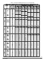
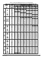
Table 5 – Air Delivery − CFM (With Filter)*
UNIT SIZE
0451412
0701712
0701716
0901714
0902116
1102120
1352420
WIRELEAD
COLOR
SPEED
Gray
Yellow
Orange
Blue
Red
Gray
Yellow
Blue
Orange
Red
Gray
Yellow
Blue
Orange
Red
Gray
Yellow
Blue
Orange
Red
Gray
Blue
Yellow
Orange
Red
Gray
Yellow
Blue
Orange
Red
Gray
Blue
Yellow
Orange
Red
5
4
3
2
1
5
4
3
2
1
5
4
3
2
1
5
4
3
2
13
5
4
3
2
13
5
4
3
2
1
5
4
3
2
13
Test Airflow Delivery @ Various External Static Pressures (in. w.c.)
0.1
0.2
0.3
0.4
0.5
0.6
0.7
0.8
0.9
1
1230
980
770
710
600
1185
1000
990
855
860
1610
1385
1215
1175
1080
1355
1295
1220
1030
945
1625
1440
1425
1260
1095
2255
1600
1945
1420
1280
2065
1825
1760
1620
1325
1190
945
720
660
540
1140
940
935
775
685
1565
1335
1165
1130
1015
1320
1255
1185
985
905
1580
1395
1380
1210
1040
2205
1525
1890
1340
1205
2005
1760
1690
1550
1260
1155
920
685
620
500
1095
895
895
720
515
1525
1290
1120
1085
955
1285
1220
1150
940
855
1535
1350
1335
1160
980
2150
1465
1830
1280
1140
1940
1695
1625
1480
1185
1120
890
640
580
455
1055
850
845
660
445
1475
1250
1075
1035
920
1245
1185
1105
900
800
1490
1305
1290
1105
905
2100
1400
1770
1200
1055
1875
1630
1555
1405
1100
1080
855
600
540
415
1005
800
790
605
385
1435
1205
1035
990
875
1210
1140
1065
845
750
1445
1255
1235
1050
845
2040
1335
1715
1140
990
1810
1560
1485
1335
1025
1045
815
560
490
385
960
750
740
560
340
1395
1165
985
945
820
1165
1100
1025
790
670
1395
1200
1185
990
780
1985
1275
1655
1065
910
1740
1490
1415
1260
955
1010
770
520
455
345
915
695
690
495
275
1350
1125
940
900
780
1125
1055
975
715
600
1340
1145
1125
935
720
1920
1210
1600
1005
840
1670
1420
1345
1195
885
975
735
475
415
305
865
650
640
435
205
1305
1075
895
855
725
1080
1005
915
655
540
1260
1090
1075
880
650
1835
1150
1545
925
760
1600
1350
1275
1130
805
935
690
430
375
235
820
600
590
385
−−
1260
1025
845
805
670
1025
955
840
590
490
1135
1040
1020
820
585
1735
1080
1480
865
695
1530
1275
1200
1065
735
895
645
385
335
−−
780
555
535
335
−−
1215
980
840
760
620
815
815
740
535
435
995
950
940
755
520
1615
1015
1430
790
630
1470
1205
1130
995
670
NOTES:
1. A filter is required for each return−air inlet. Airflow performance includes a 3/4 in. (19 mm) washable filter media such as
contained in factory−authorized accessory filter rack. See accessory list. To determine airflow performance without this filter,
assume an additional 0.1 in. W.C. available external static pressure.
2. ADJUST THE BLOWER SPEED TAPS AS NECESSARY FOR THE PROPER AIR TEMPERATURE RISE FOR EACH
INSTALLATION.
3. Highlighted areas indicate airflow range is beyond the range allowed for heating. THESE AIRFLOW RANGES MAY ONLY BE
USED FOR COOLING.
−− Indicates unstable operating conditions.
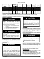
Table 6 – Maximum Capacity of Pipe*
NOMINAL IRON
PIPE
SIZE IN. (mm)
1/2 (13)
3/4 (19)
1 (25)
1−1/4 (32)
1−1/2 (38)
INTERNAL
DIAMETER
In. (mm)
0.622 (16)
0.824 (21)
1.049 (27)
1.380 (35)
1.610 (41)
LENGTH OF PIPE − FT. (M)
10
175 (53)
360 (110)
680 (207)
1400 (427)
2100 (640)
20
120 (37)
250 (76)
465 (142)
950 (290)
1460 (445)
30
97 (30)
200 (61)
375 (114)
770 (235)
1180 (360)
40
82 (25)
170 (52)
320 (98)
660 (201)
990 (301)
50
73 (22)
151 (46)
285 (87)
580 (177)
900 (274)
* Cubic ft. of natural gas per hr for gas pressures of 0.5 psig (14−in. w.c.) or less and a pressure drop of 0.5−in. w.c. (based on a 0.60 specific gravity
gas). Ref: Chapter 6 ANSI Z223−2012/NFPA 54−2012.
Piping should be pressure and leak tested in accordance with
NFGC in the United States, local, and national plumbing and
gas codes before the furnace has been connected. After all
connections have been made, purge lines and check for
leakage at furnace prior to operating furnace.
If pressure exceeds 0.5 psig (14−in. w.c.), gas supply pipe
must be disconnected from furnace and capped before and
during supply pipe pressure test. If test pressure is equal to or
less than 0.5 psig (14−in. w.c.), turn off electric shutoff switch
441 01 1421 01
located on furnace gas control valve and accessible manual
equipment shutoff valve before and during supply pipe
pressure test. After all connections have been made, purge
lines and check for leakage at furnace prior to operating
furnace.
The gas supply pressure shall be within the maximum and
minimum inlet supply pressures marked on the rating plate
with the furnace burners ON and OFF.
Specifications are subject to change without notice.
17
Figure 20 − Upflow Return Air Configurations and Restrictions
5 TONS AND
GREATER *
* 2000 CFM AND GREATER AT .6 ESP HI COOLING SPEED
Figure 21 − Downflow Return Air Configurations and Restrictions
5 TONS AND
GREATER *
* 2000 CFM AND GREATER AT .6 ESP HI COOLING SPEED
Figure 22 − Horizontal Return Air Configurations and Restrictions
5 TONS AND
GREATER *
* 2000 CFM AND GREATER AT .6 ESP HI COOLING SPEED
18
Specifications are subject to change without notice.
441 01 1421 01
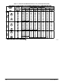
Table 7 – Electrical Data
FURNACE
MODEL
0451412
0701712
0701716
0901714
0902116
1102120
1352420
Volts−
Hertz−
Phase
115-60-1
115-60-1
115-60-1
115-60-1
115-60-1
115-60-1
115-60-1
Operating
Voltage* Range
MaxiMinimum
mum
127
127
127
127
127
127
127
104
104
104
104
104
104
104
Maximum
Unit Amps
5.6
5.6
10.0
8.2
8.2
13.4
10.7
Minimum
Wire Size
AWG
Unit
Ampacity#
7.8
7.8
13.3
11.0
11.0
17.4
14.0
14.0
14.0
14.0
14.0
14.0
12.0
14.0
Maximum
Maximum
Wire Length‡ Fuse or CKT
ft (m)
BKR† Amps
47.0
47.0
27.0
33.0
33.0
33.0
26.0
(14.3)
(14.3)
(8.2)
(10.1)
(10.1)
(10.1)
(7.9)
* Permissible limits of the voltage range at which the unit operates satisfactorily.
# Unit ampacity = 125 percent of largest operating component’s full load amps plus 100 percent of all other potential operating components’ (EAC, humidifier,
etc.) full load amps.
{ Time−delay type is recommended.
} Length shown is as measured 1 way along wire path between unit and service panel for maximum 2 percent voltage drop.
ELECTRICAL CONNECTIONS
!
!
WARNING
ELECTRICAL SHOCK, FIRE OR EXPLOSION HAZARD
Failure to follow safety warnings could result in
dangerous operation, serious injury, death or property
damage.
Improper servicing could result in dangerous operation,
serious injury, death or property damage.
S Before servicing, disconnect all electrical power
to furnace.
S When servicing controls, label all wires prior to
disconnecting. Reconnect wires correctly.
S Verify proper operation after servicing.
!
WARNING
ELECTRICAL SHOCK HAZARD
Failure to follow this warning could result in personal
injury or death.
Blower access panel door switch opens 115−v power to
control. No component operation can occur. Do not
bypass or close switch with panel removed.
See Figure 26 for field wiring diagram showing typical field
115−v wiring. Check all factory and field electrical
connections for tightness.
Field−supplied wiring shall conform with the limitations of
63_F (35_C) rise.
!
WARNING
ELECTRICAL SHOCK AND FIRE HAZARD
Failure to follow this warning could result in personal
injury, death, or property damage.
The cabinet MUST have an uninterrupted or unbroken
ground according to NEC NFPA 70−2011 or local codes
to minimize personal injury if an electrical fault should
occur. This may consist of electrical wire, conduit
approved for electrical ground or a listed, grounded power
cord (where permitted by local code) when installed in
accordance with existing electrical codes. Refer to the
power cord manufacturer’s ratings for proper wire gauge.
Do not use gas piping as an electrical ground.
441 01 1421 01
15.0
15.0
15.0
15.0
15.0
20.0
15.0
CAUTION
FURNACE MAY NOT OPERATE
Failure to follow this caution may result in intermittent
furnace operation.
Furnace control must be grounded for proper
operation or else control will lock out. Control must
remain grounded through green/yellow wire routed to
gas valve and manifold bracket screw.
115−V WIRING
Verify that the voltage, frequency, and phase correspond to
that specified on unit rating plate. Also, check to be sure that
service provided by utility is sufficient to handle load imposed
by this equipment. Refer to rating plate or Table 7 for
equipment electrical specifications.
Make all electrical connections in accordance with National
Electrical Code (NEC) NFPA 70−2011 and any local codes or
ordinances that might apply.
!
WARNING
FIRE HAZARD
Failure to follow this warning could result in personal
injury, death, or property damage.
Do not connect aluminum wire between disconnect
switch and furnace. Use only copper wire.
Use a separate, fused branch electrical circuit with a properly
sized fuse or circuit breaker for this furnace. See Table 7 for
wire size and fuse specifications. A readily accessible means
of electrical disconnect must be located within sight of the
furnace.
NOTE: Proper polarity must be maintained for 115−v wiring.
If polarity is incorrect, control LED status indicator light will
flash a status code 10 and furnace will NOT operate.
J−BOX RELOCATION
NOTE: If factory location of J−Box is acceptable, go to next
section (ELECTRICAL CONNECTION TO J−BOX).
NOTE: On 14−in. (356 mm) wide casing models, the J−Box
shall not be relocated to other side of furnace casing when
the vent pipe is routed within the casing.
1. Remove and save two screws holding J−Box.
Specifications are subject to change without notice.
19
NOTE: The J−Box cover need not be removed from the
J−Box in order to move the J−Box. Do NOT remove green
ground screw inside J−Box.
2. Cut wire tie on loop in furnace wires attached to J−box.
3. Move J−Box to desired location.
4. Fasten J−Box to casing with two screws removed in
Step 1.
5. Route J−Box wires within furnace away from sharp
edges, rotating parts and hot surfaces.
ELECTRICAL CONNECTION TO J−BOX
Electrical Box on Furnace Casing Side
!
Figure 23 − Relocating J−Box
FACTORY
INSTALLED
LOCATION
ALTERNATE
FIELD
LOCATION
WARNING
FIRE OR ELECTRICAL SHOCK HAZARD
Failure to follow this warning could result in personal
injury, death, or property damage.
If field−supplied manual disconnect switch is to be
mounted on furnace casing side, select a location
where a drill or fastener cannot damage electrical or
gas components.
Figure 24 − Field−Supplied Electrical Box on Furnace
Casing
1. Select and remove a hole knockout in the casing
where the electrical box is to be installed.
NOTE: Check that duct on side of furnace will not interfere
with installed electrical box.
2. Remove the desired electrical box hole knockout and
position the hole in the electrical box over the hole in
the furnace casing.
3. Fasten the electrical box to casing by driving two field
supplied screws from inside electrical box into casing
steel.
4. Remove and save two screws holding J−Box.
5. Pull furnace power wires out of 1/2−in. (12 mm) diameter hole in J−Box. Do not loosen wires from strain−relief
wire−tie on outside of J−Box.
6. Route furnace power wires through holes in casing and
electrical box and into electrical box.
7. Pull field power wires into electrical box.
8. Remove cover from furnace J−Box.
9. Route field ground wire through holes in electrical box
and casing, and into furnace J−Box.
10. Reattach furnace J−Box to furnace casing with screws
removed in Step 4.
11. Secure field ground wire to J−Box green ground screw.
12. Complete electrical box wiring and installation. Connect
line voltage leads as shown in Figure 26. Use best
practices (NEC in U.S. for wire bushings, strain relief,
etc.
13. Reinstall cover to J−Box. Do not pinch wires between
cover and bracket.
20
Specifications are subject to change without notice.
A10141
441 01 1421 01
POWER CORD INSTALLATION IN FURNACE J−BOX
NOTE: Power cords must be able to handle the electrical
requirements listed in Table 7. Refer to power cord
manufacturer’s listings.
1. Remove cover from J−Box.
2. Route listed power cord through 7/8−in. (22 mm) diameter hole in J−Box.
3. Secure power cord to J−Box bracket with a strain relief
bushing or a connector approved for the type of cord
used.
4. Secure field ground wire to green ground screw on
J−Box bracket.
5. Connect line voltage leads as shown in Figure 26.
6. Reinstall cover to J−Box. Do not pinch wires between
cover and bracket.
BX CABLE INSTALLATION IN FURNACE J−BOX
1. Remove cover from J−Box.
2. Route BX cable into 7/8−inch diameter hole in J−Box.
3. Secure BX cable to J−Box bracket with connectors approved for the type of cable used.
4. Secure field ground wire to green ground screw on
J−Box bracket.
5. Connect line voltage leads as shown in Figure 26 .
6. Reinstall cover to J−Box. Do not pinch wires between
cover and bracket.
24−V WIRING
Make field 24−v connections at the 24−v terminal strip. (See
Figure 24) Connect terminal Y/Y2 as shown in Figure 25 for
proper cooling operation. Use only AWG No. 18,
color−coded, copper thermostat wire.
The 24−v circuit contains an automotive−type, 3−amp. fuse
located on the control. Any direct shorts during installation,
service, or maintenance could cause this fuse to blow. If fuse
replacement is required, use ONLY a 3−amp. fuse of identical
size.
441 01 1421 01
ACCESSORIES
1. Electronic Air Cleaner (EAC):
Connect an accessory Electronic Air Cleaner (if used)
using 1/4−in female quick connect terminals to the two
male 1/4−in quick−connect terminals on the control
board marked EAC 1 AMP and NEUTRAL. The terminals are rated for 115 VAC, 1.0 amps maximum and are
energized during blower motor operation. (See
Figure 25)
2. Humidifier (HUM 24VAC and HUM)
S
a.
HUM 24VAC: Connect an accessory 24
VAC, 0.5 amp maximum humidifier (if used) to the
1/4−in male quick−connect HUM 24VAC terminal
and C screw terminal on the control board thermostat strip. The HUM 24VAC terminal is energized
when there is a call for heat (W) and the pressure
switch (PRS) closes. (See Figure 25 and Figure 48).
S
b.
HUM: Connect an accessory 115VAC (EAC
and HUM are 1 amp maximum combined) humidifier
(if used) to the ¼−inch male quick connect HUM
terminal and NEUTRAL ¼−inch quick connect. The
HUM terminal is energized when the inducer motor
is energized (IDR). (See Figure 25 and Figure 48).
NOTE: A field−supplied, 115−v controlled relay connected to
EAC terminals may be added if humidifier operation is
desired during blower operation.
NOTE: DO NOT connect furnace control HUM 24VAC
terminal to H (humidifier) terminal on humidity sensing
thermostat, or similar device. See humidity sensing
thermostat, thermostat, or controller manufacturer’s
instructions for proper connection.
Specifications are subject to change without notice.
21
Figure 25 − Furnace Control
HEAT
OFFïDELAY
J2 JUMPER
TWINNING AND/OR
COMPONENT TEST
TERMINAL
24ïV THERMOSTAT
TERMINALS
HUMIDIFIER TERMINAL
(24ïVAC 0.5 AMP MAX)
3ïAMP FUSE
TRANSFORMER 24ïVAC
CONNECTIONS
LED OPERATION &
DIAGNOSTIC LIGHT
P1 ï LOW VOLTAGE MAIN
HARNESS CONNECTOR
P2
HOT SURFACE IGNITOR (HSI)
& INDUCER MOTOR (IND)
CONNECTOR
BLOWER SPEED
SELECTION TERMINALS
115 VAC
BLOWER
POWER (BLï1)
CONNECTION
IND
115ïVAC (L2) NEUTRAL
CONNECTIONS
HSI
115 VAC
(L1) LINE VOLTAGE
CONNECTION
EAC TERMINAL
(115 VAC 1.0 AMP MAX.)
HUMIDIFIER
TERMINAL
115ïVAC
115 VAC
TRANSFORMER
PRIMARY
L15F001
Figure 26 − Heating and Cooling Application Wiring Diagram with Single−Stage Thermostat
FIELD 24-VOLT WIRING
FIELD 115-, 208/230-, 460-VOLT WIRING
FACTORY 24-VOLT WIRING
FACTORY 115-VOLT WIRING
NOTE 2
W
FIVE
WIRE
C
Y
R
G
1-STAGE
THERMOSTAT
TERMINALS
FIELD-SUPPLIED
FUSED DISCONNECT
THREE-WIRE
HEATINGONLY
BLK
BLK
W2
WHT
WHT
COM
208/230- OR
460-VOLT
THREE
PHASE
W/W1
GND
115-VOLT FIELDSUPPLIED
FUSED
DISCONNECT
JUNCTION
BOX
CONTROL
BOX
Y/Y2
R
GND
208/230VOLT
SINGLE
PHASE
CONDENSING
UNIT
G
24-VOLT
TERMINAL
BLOCK
FURNACE
22
NOTE 1
NOTES: 1. Connect Y/Y2-terminal as shown for proper operation.
2. Some thermostats require a "C" terminal connection as shown.
3. If any of the original wire, as supplied, must be replaced, use
same type or equivalent wire.
Specifications are subject to change without notice.
441 01 1421 01
VENTING
The furnace shall be connected to a listed factory built
chimney or vent, or a clay−tile lined masonry or concrete
chimney. Venting into an unlined masonry chimney or
concrete chimney is prohibited.
When an existing Category I furnace is removed or replaced,
the original venting system may no longer be sized to
properly vent the attached appliances. An improperly sized
Category I venting system could cause the formation of
condensate in the furnace and vent, leakage of condensate
and combustion products, and spillage of combustion
products into the living space.
Vent system or vent connectors may need to be re−sized.
Vent systems or vent connectors, must be sized to approach
minimum size as determined using appropriate table found in
the NFGC.
!
WARNING
CARBON MONOXIDE POISONING HAZARD
Failure to follow the steps outlined below for each
appliance connected to the venting system being placed
into operation could result in carbon monoxide poisoning
or death. The following steps shall be followed for each
appliance connected to the venting system being placed
into operation, while all other appliances connected to the
venting system are not in operation:
1. Seal any unused openings in venting system.
2. Inspect the venting system for proper size and
horizontal pitch, as required in the National Fuel
Gas Code, ANSI Z223.1/NFPA 54. Determine that
there is no blockage or restriction, leakage,
corrosion and other deficiencies, which could
cause an unsafe condition.
3. As far as practical, close all building doors and
windows and all doors between the space in which
the appliance(s) connected to the venting system
are located and other spaces of the building.
4. Close fireplace dampers.
5. Turn on clothes dryers and any appliance not
connected to the venting system. Turn on any
exhaust fans, such as range hoods and bathroom
exhausts, so they are operating at maximum
speed. Do not operate a summer exhaust fan.
6. Follow the lighting instructions. Place the appliance
being inspected into operation. Adjust the
thermostat so appliance is operating continuously.
7. Test for spillage from draft hood equipped
appliances at the draft hood relief opening after 5
minutes of main burner operation. Use the flame of
a match or candle.
8. If improper venting is observed during any of the
above tests, the venting system must be corrected
in accordance with the National Fuel Gas Code,
ANSI Z223.1/NFPA 54.
9. After it has been determined that each appliance
connected to the venting system properly vents
when tested as outlined above, return doors,
windows, exhaust fans, fireplace dampers and any
other gas−fired burning appliance to their previous
conditions of use.
441 01 1421 01
GENERAL VENTING REQUIREMENTS
Follow all safety codes for proper vent sizing and installation
requirements, including local building codes, the National
Fuel Gas Code ANSI Z223.1−2012/NFPA 54−2012 (NFGC),
Parts 12 and 13, the local building codes, and furnace and
vent manufacturers’ instructions.
These furnaces are design−certified as Category I furnaces in
accordance with ANSI Z21.47−2012/CSA 2.3−2012 and
operate with a non−positive vent static pressure to minimize
the potential for vent gas leakage. Category I furnaces
operate with a flue loss not less than 17 percent to minimize
the potential for condensation in the venting system. These
furnaces are approved for common venting and multistory
venting with other fan assisted or draft hood equipped
appliances in accordance with the NFGC, the local building
codes, and furnace and vent manufacturers’ instructions. The
following information and warning must be considered in
addition to the requirements defined in the NFGC.
1. If a vent (common or dedicated) becomes blocked, the
furnace will be shut off by the draft safeguard switch
located on the vent elbow.
2. Do not vent this Category I furnace into a single−wall
dedicated or common vent. The dedicated or common
vent is considered to be the vertical portion of the vent
system that terminates outdoors.
3. Vent connectors serving Category I furnaces shall not
be connected into any portion of a mechanical draft
system operating under positive pressure.
4. Do not vent this appliance with any solid fuel burning
appliance.
5. Category I furnaces must be vented vertically or nearly
vertically unless equipped with a listed power venter.
6. Do not vent this appliance into an unlined masonry
chimney. Refer to Chimney Inspection Chart,
Figure 27.
MASONRY CHIMNEY REQUIREMENTS
NOTE: These furnaces are CSA design−certified for use in
exterior tile−lined masonry chimneys with a factory accessory
Chimney Adapter Kit. Refer to the furnace rating plate for
correct kit usage. The Chimney Adapter Kits are for use with
ONLY furnaces having a Chimney Adapter Kit numbers
marked on the furnace rating plate.
If a clay tile−lined masonry chimney is being used and it is
exposed to the outdoors below the roof line, relining might be
required. Chimneys shall conform to the Standard for
Chimneys, Fireplaces, Vents, and Solid Fuel Burning
Appliances ANSI/NFPA 211−2012 and must be in good
condition.
U.S.A.−Refer to Sections 13.1.8 and 13.2.20 of the NFGC
NFPA 54/ANSI Z223.1−2012 or the authority having
jurisdiction to determine whether relining is required. If relining
is required, use a properly sized listed metal liner, Type−B
vent, or a listed alternative venting design.
NOTE: See the NFPA 54/ANSI Z223.1−2012, 13.1.8 and
13.2.20 regarding alternative venting design and the
Exception, which cover installations such as the Chimney
Adapter Kits, which are listed for use with these furnaces.
The Chimney Adapter Kit is listed alternative venting system
for these furnaces. See the kit instructions for complete
details.
This furnace is permitted to be vented into a clay tile−lined
masonry chimney that is exposed to the outdoors below the
roof line, provided:
1. Vent connector is Type−B double−wall, and
2. This furnace is common vented with at least 1 draft
hood equipped appliance, and
3. The combined appliance input rating is less than the
maximum capacity given in Table 8, and
Specifications are subject to change without notice.
23
4. The input rating of each space heating appliance is
greater than the minimum input rating given in Table 9
for the local 99% Winter Design Temperature. Chimneys having internal areas greater than 38 square
inches require furnace input ratings greater than the input ratings of these furnaces. See footnote at bottom of
Table 9, and
5. The authority having jurisdiction approves.
If all of these conditions cannot be met, an alternative venting
design shall be used, such as the listed chimney adapter kit
with these furnaces, which are listed for use with the kit, a
listed chimney−lining system, or a Type−B common vent.
Inspections before the sale and at the time of installation will
determine the acceptability of the chimney or the need for
repair and/or (re)lining. Refer to the Figure 27 to perform a
chimney inspection. If the inspection of a previously used
tile−lined chimney:
a. Shows signs of vent gas condensation, the chimney
should be relined in accordance with local codes and
the authority having jurisdiction. The chimney should
be relined with a listed metal liner, Type−B vent, or a
listed chimney adapter kit shall be used to reduce condensation. If a condensate drain is required by local
code, refer to the NFGC NFPA 54/ANSI Z223.1−2012,
Section 12.10 for additional information on condensate drains.
b. Indicates the chimney exceeds the maximum permissible size in the tables, the chimney should be rebuilt or relined to conform to the requirements of the
equipment being installed and the authority having jurisdiction.
A chimney without a clay tile liner, which is otherwise in good
condition, shall be rebuilt to conform to ANSI/NFPA 211 or be
lined with a UL listed metal liner or UL listed Type−B vent.
Relining with a listed metal liner or Type−B vent is considered
to be a vent−in−a−chase.
If a metal liner or Type−B vent is used to line a chimney, no
other appliance shall be vented into the annular space
between the chimney and the metal liner.
Exterior Masonry Chimney FAN + NAT
Installations with Type−B Double Wall Vent
Connectors {NFPA & AGA
Table 8 – Combined Appliance Maximum Input Rating in
Thousands of BTUH per Hour
VENT HEIGHT
FT. (M)
6 (1.8)
8 (2.4)
10 (3.0)
15 (4.5)
20 (6.0)
30 (9.1)
INTERNAL AREA OF CHIMNEY
IN2 (MM2)
12
(7741)
74
80
84
NR
NR
NR
19
(12258)
119
130
138
152
NR
NR
28
(18064)
178
193
207
233
250
NR
38
(24516)
257
279
299
334
368
404
Table 9 – Minimum Allowable Input Rating of Space−
Heating Appliance in Thousands of BTUH per Hour
INTERNAL AREA OF CHIMNEY
IN2. (MM2)
12
19
28
38
(7741)
(12258)
(18064)
(24516)
Local 99% Winter Design
Temperature: 17 to 26_F (-8 to -3_C)
6 (1.8)
0
55
99
141
8 (2.4)
52
74
111
154
10 (3.0)
NR
90
125
169
15 (4.6)
NR
NR
167
212
20 (6.1)
NR
NR
212
258
30 (9.1)
NR
NR
NR
362
Local 99% Winter Design
Temperature: 5 to 16_F* (-15 to -9_C)
6 (1.8)
NR
78
121
166
8 (2.4)
NR
94
135
182
10 (3.0)
NR
111
149
198
15 (4.6)
NR
NR
193
247
VENT HEIGHT
FT (M)
24
20 (6.1)
30 (9.1)
NR
NR
NR
NR
NR
NR
Local 99% Winter Design
Temperature: -10 to 4_F* (-23 to -16_C)
6 (1.8)
NR
NR
145
8 (2.4)
NR
NR
159
10 (3.0)
NR
NR
175
15 (4.6)
NR
NR
NR
20 (6.1)
NR
NR
NR
30 (9.1)
NR
NR
NR
Local 99% Winter Design
Temperature: -11_F (-24_C) or lower
Not recommended for any vent configuration.
293
377
196
213
231
283
333
NR
*The 99.6% heating db temperatures found in the 1997 or 2001 ASHRAE
Fundamentals Handbook, Climatic Design Information chapter, Table 1A (United States) or the 2005 ASHRAE Fundamentals handbook, Climatic Design
Information chapter, and the CD−ROM included with the 2005 ASHRAE Fundamentals Handbook.
APPLIANCE APPLICATION REQUIREMENTS
Appliance operation has a significant impact on the
performance of the venting system. If the appliances are
sized, installed, adjusted, and operated properly, the venting
system and/or the appliances should not suffer from
condensation and corrosion. The venting system and all
appliances shall be installed in accordance with applicable
listings, standards, and codes.
The furnace should be sized to provide 100 percent of the
design heating load requirement plus any margin that occurs
because of furnace model size capacity increments. Heating
load estimates can be made using approved methods
available from Air Conditioning Contractors of America
(Manual J); American Society of Heating, Refrigerating, and
Air−Conditioning Engineers; or other approved engineering
methods. Excessive oversizing of the furnace could cause
the furnace and/or vent to fail prematurely. When a metal vent
or metal liner is used, the vent must be in good condition and
be installed in accordance with the vent manufacturer’s
instructions.
To prevent condensation in the furnace and vent system, the
following precautions must be observed:
1. The return−air temperature must be at least 60_F
(16_C)db except for brief periods of time during warm−
up from setback at no lower than 55_F (13_C) db or
during initial start−up from a standby condition.
2. Adjust the gas input rate per the installation instructions. Low gas input rate causes low vent gas temperatures, causing condensation and corrosion in the furnace and/or venting system. Derating is permitted only
for altitudes above 2000 ft. (610 M).
3. Adjust the air temperature rise to the midpoint of the
rise range or slightly above. Low air temperature rise
can cause low vent gas temperature and potential for
condensation problems.
4. Set the thermostat heat anticipator or cycle rate to reduce short cycling.
Air for combustion must not be contaminated by halogen
compounds which include chlorides, fluorides, bromides, and
iodides. These compounds are found in many common home
products such as detergent, paint, glue, aerosol spray,
bleach, cleaning solvent, salt, and air freshener, and can
cause corrosion of furnaces and vents. Avoid using such
products in the combustion−air supply. Furnace use during
construction of the building could cause the furnace to be
exposed to halogen compounds, causing premature failure of
the furnace or venting system due to corrosion.
Vent dampers on any appliance connected to the common
vent can cause condensation and corrosion in the venting
system. Do not use vent dampers on appliances common
vented with this furnace.
ADDITIONAL VENTING REQUIREMENTS
A 4” (101 mm) round vent elbow is supplied with the furnace.
A 5−inch (127 mm) or 6− inch (152 mm) vent connector may
Specifications are subject to change without notice.
441 01 1421 01
be required for some model furnaces. A field−supplied
4−inch−to−5−inch (101 − 127 mm) or 4−inch−to−6−inch (101
− 152 mm) sheet metal increaser fitting is required when
5−inch (127 mm) or 6−inch (152 mm) vent connector is used.
See Figure 28 − Figure 40 Venting Orientation for approved
vent configurations.
NOTE: Vent connector length for connector sizing starts at
furnace vent elbow. The 4−inch vent elbow is shipped for
upflow configuration and may be rotated for other positions.
Remove the 3 screws that secure vent elbow to furnace,
rotate furnace vent elbow to position desired, reinstall screws.
The factory−supplied vent elbow does NOT count as part of
the number of vent connector elbows.
The vent connector can exit the furnace through one of 5
locations on the casing.
1. Attach the single wall vent connector to the furnace
vent elbow, and fasten the vent connector to the vent
elbow with at least two field−supplied, corrosion−resistant, sheet metal screws located 180_ apart.
NOTE: A flue extension is recommended to extend from the
furnace elbow to outside the furnace casing. If flue extension
is used, fasten the flue extension to the vent elbow with at
least two field−supplied, corrosion−resistant, sheet metal
441 01 1421 01
screws located 180_ apart. Fasten the vent connector to the
flue extension with at least two field−supplied, corrosion
resistant sheet metal screws located 180_ apart.
2. Vent the furnace with the appropriate connector as
shown in Figure 28 − Figure 40.
3. Determine the correct location of the knockout to be removed.
4. Use a hammer and screwdriver to strike a sharp blow
between the tie points and work the slug back and forth
until the slug breaks free.
!
CAUTION
CUT HAZARD
Failure to follow this caution may result in personal
injury.
Sheet metal parts may have sharp edges or burrs.
Use care and wear appropriate protective clothing,
safety glasses and gloves when handling parts and
servicing furnaces.
Specifications are subject to change without notice.
25
Figure 27 − Chimney Inspection Chart
26
Specifications are subject to change without notice.
441 01 1421 01
The horizontal portion of the venting system shall slope
upwards not less than 1/4−in. per linear ft. (21 mm/M) from
the furnace to the vent and shall be rigidly supported every 5
ft. (2 M) or less with metal hangers or straps to ensure there
BURN HAZARD
is no movement after installation.
Failure to follow this caution may cause personal
SIDEWALL VENTING
injury.
This furnace is not approved for direct sidewall horizontal
Hot vent pipe is within reach of small children when
venting.
installed in downflow position. See the following
Per section 12.4.3 of the NFPA 54/ANSI Z223.1−2012, any
instruction.
listed mechanical venter may be used, when approved by the
authority having jurisdiction.
An accessory Vent Guard Kit is REQUIRED for downflow
Select the listed mechanical venter to match the Btuh input of
applications where the vent exits through the lower portion of
the furnace being vented. Follow all manufacturer’s
the furnace casing. See Figure 32. Refer to the Vent Guard
installation requirements for venting and termination included
Kit Instructions for complete details.
with the listed mechanical venter.
Caution!! For the following applications, use the minimum vertical vent heights as specified below. For all other
applications, follow exclusively the National Fuel Gas Code.
!
FURNACE
ORIENTATION
Downflow
Horizontal Left
Horizontal Left
CAUTION
132,000
MIN. VENT
DIAMETER
IN (MM)*
5 (127 )
MIN. VERTICAL VENT
HEIGHT
FT. (M)**
12 (4)
132,000
5 (127 )
7 (2)
132,000
5 (127 )
7 (2)
FURNACE INPUT
(BTUH/HR)
VENT ORIENTATION
Vent elbow left, then up Figure 32
Vent elbow right, then up
Figure 35
Vent elbow right Figure 36
NOTE: All vent configurations must also meet National Fuel Gas Code venting requirements NFGC
*4 in. (102 mm) inside casing or vent guard
**Including 4 in. (102 mm) vent section(s)
Figure 28 − Upflow Application−Vent Elbow Up
Figure 29 − Upflow Application−Vent Elbow Right
SEE NOTES: 1,2,4,7,8,9
on the page following
these figures
SEE NOTES: 1,2,3,4,7,8,9
on the pages following
these figures
A03208
441 01 1421 01
Specifications are subject to change without notice.
A03209
27
Figure 30 − Downflow Application−Vent Elbow Up then
Left
Figure 32 − Downflow Application−Vent Elbow Left then
Up
SEE NOTES:1,2,3,4,5,7,8,9
on the page following
these figures
SEE NOTES: 1,2,4,5,6,7,8,9
on the page following these figures
A03210
Figure 31 − Downflow Application−Vent Elbow Up
A03207
Figure 33 − Downflow Application−Vent Elbow Up then
Right
SEE NOTES: 1,2,4,5,7,8,9
on the page following
these figures
SEE NOTES:1,2,3,4,5,7,8,9
on the page following
these figures.
A03211
A03212
28
Specifications are subject to change without notice.
441 01 1421 01
Figure 34 − Horizontal Left Application−Vent Elbow Left
Figure 38 − Horizontal Right Application−Vent Elbow Left
then Up
SEE NOTES: 1,2,4,7,8,9 on the page
following these figures
A03213
Figure 35 − Horizontal Left Application−Vent Elbow Right
then Up
SEE NOTES: 1,2,4,5,7,8,9 on the page
following these figures
A03219
Figure 39 − Horizontal Left Application−Vent Elbow Right
SEE NOTES: 1,2,4,5,7,8,9 on the page
following these figures
SEE NOTES: 1,2,4,5,7,8,9 on the page
following these figures
A03216
A03214
Figure 36 − Horizontal Right Application−Vent Elbow
Right
Figure 40 − Horizontal Right Application−Vent Elbow Left
SEE NOTES: 1,2,4,7,8,9 on the page
following these figures
SEE NOTES: 1,2,4,5,7,8,9
A03214
Figure 37 − Horizontal Left Application−Vent Elbow Up
SEE NOTES: 1,2,4,5,7,8,9 on the page
following these figures
A03215
441 01 1421 01
A02068
Venting Notes for Figure 28 − Figure 40
1. For common vent, vent connector sizing and vent
material: United States−−use the NFGC.
2. Immediately increase to 5−inch (127 mm) or 6−inch
(152 mm) vent connector outside furnace casing when
5−inch (127 mm) vent connector is required, refer to
Note 1 above.
3. Side outlet vent for upflow and downflow installations
must use Type B vent immediately after exiting the
furnace, except when Downflow Vent Guard Kit, is
used in the downflow position.
4. Type−B vent where required, refer to Note 1 above.
Specifications are subject to change without notice.
29
5. Four−inch single−wall (26 ga. min.) vent must be used
inside furnace casing and when the Downflow Vent
Guard Kit is used external to the furnace.
6. Accessory Downflow Vent Guard Kit, required in
downflow installations with lower vent configuration.
7. Chimney Adapter Kit may be required for exterior
masonry chimney applications. Refer to Chimney
Adapter Kit, for sizing and complete application details.
8. Secure vent connector to furnace elbow with (2)
corrosion−resistant sheet metal screws, spaced
approximately 180_ apart.
9. Secure all other single wall vent connector joints with
(3) corrosion resistant screws spaced approximately
120_ apart. Secure Type−B vent connectors per vent
connector manufacturer’s recommendations.
START−UP, ADJUSTMENT, AND SAFETY
CHECK
Step 1 —General
!
FIRE HAZARD
WARNING
Step 2 —Start−Up Procedures
!
Failure to follow this warning could cause personal
injury, death and/or property damage.
Never test for gas leaks with an open flame. Use a
commercially available soap solution made
specifically for the detection of leaks to check all
connections.
1. Purge gas lines after all connections have been made.
2. Check gas lines for leaks.
3. To Begin Component Self−Test:
Remove blower access door. Disconnect the thermostat R lead from the furnace control board. Manually
close the blower door switch closed. Short (jumper) the
C terminal on control to the TEST/TWIN 3/16−inch
quick connect terminal on control until LED goes out
(approximately 2 sec). Gas valve and humidifier will not
be turned on. (See Figure 25)
Failure to follow this warning could result in personal
injury, death and/or property damage.
This furnace is equipped with manual reset limit
switches in the gas control area. The switches open
and shut off power to the gas valve if a flame rollout or
overheating condition occurs in the gas control area.
DO NOT bypass the switches. Correct inadequate
combustion air supply problem before resetting the
switches.
!
CAUTION
CUT HAZARD
Failure to follow this caution may result in personal
injury.
Sheet metal parts may have sharp edges or burrs.
Use care and wear appropriate protective clothing,
safety glasses and gloves when handling parts and
servicing furnaces.
1. Maintain 115−v wiring and ground. Improper polarity
will result in flashing a status code 10 and no furnace
operation.
2. Make thermostat wire connections at the 24−v terminal
block on the furnace control. Failure to make proper
connections will result in improper operation. (See
Figure 26)
3. Gas supply pressure to the furnace must be greater
than 4.5−in. w.c. (0.16 psig ) but not exceed 14−in. w.c.
(0.5 psig).
4. Check all manual−reset switches for continuity.
5. Install blower compartment door. Door must be in place
to operate furnace.
6. Replace outer door.
30
WARNING
FIRE AND EXPLOSION HAZARD
!
WARNING
ELECTRICAL SHOCK HAZARD
Failure to follow this warning could result in personal
injury, or death.
Blower access door switch opens 115−v power to
control. No component operation can occur unless
switch is closed. Caution must be taken when
manually closing this switch for service purposes.
NOTE: The furnace control allows all components, except
the gas valve, to be run for short period of time. This feature
helps diagnose a system problem in case of a component
failure. Component test feature will not operate if any
thermostat signal is present at the control.
Component test sequence is as follows:
Refer to service label attached to furnace or see Figure 44.
a. LED will display previous status code 4 times.
NOTE: If no previous code is present, go directly to b.
b. Inducer motor starts and continues to run until Step g
of component test sequence.
c. Hot surface igniter is energized for 15 sec., then off.
d. Blower motor operates on HEAT speed for 10 sec.
e. Blower motor operates on COOL speed for 10 sec.
f. Inducer motor stops.
g. Reconnect R lead to furnace control board, release
blower door switch and re−install blower door.
4. Operate furnace per instruction on door.
5. Verify furnace shut down by lowering thermostat setting
below room temperature.
6. Verify furnace restarts by raising thermostat setting
above room temperature.
Specifications are subject to change without notice.
441 01 1421 01
Step 3 —Adjustments
!
Table 10 – Altitude Derate Multiplier for U.S.A.
WARNING
ALTITUDE
(FT. / M)
FIRE HAZARD
Failure to follow this warning could result in injury,
death and/or property damage.
DO NOT bottom out gas valve regulator adjusting
screw. This can result in unregulated manifold
pressure and result in excess overfire and heat
exchanger failures.
!
CAUTION
DERATE
MULTIPLIER
FACTOR*
1.00
0.90
0.86
0.82
0.78
0.74
0.70
0.66
0.62
* Derate multiplier factors are based on midpoint altitude for altitude range.
FURNACE DAMAGE HAZARD
Failure to follow this caution may result in reduced
furnace life.
DO NOT redrill orifices. Improper drilling (burrs,
out−of−round holes, etc.) can cause excessive burner
noise and misdirection of burner flames. This can
result in flame impingement of heat exchangers,
causing failures. (See Figure 42)
Furnace gas input rate on rating plate is for installations at
altitudes up to 2000 ft. (610 M). Furnace input rate must be
within +/−2 percent of furnace rating plate input. For altitudes
above 5500 ft. (1676 M), a field−supplied high altitude
pressure switch is required.
1. Determine the correct gas input rate.
The input rating for altitudes above 2,000 ft. (610 M)
must be reduced by 4 percent for each 1,000 ft. (305
M) above sea level. For installations below 2000 ft.
(610 M), refer to the unit rating plate. For installations
above 2000 ft. (610 M), multiply the input on the rating
plate by the de−rate multiplier in Table 8 for the correct
input rate.
2. Determine the correct orifice and manifold pressure adjustment. There are two different orifice and manifold
adjustment tables. All models in all positions, except
Low NOx models in downflow or horizontal positions,
use Table 13 (22,000 Btuh/Burner).
Low NOx models in the downflow or horizontal positions must use Table 14 (21,000 Btuh/Burner). See input listed on rating plate.
a. Obtain average yearly gas heat value (at installed altitude) from local gas supplier.
b. Obtain average yearly gas specific gravity from local
gas supplier.
c. Find installation altitude in Table 13 or 14.
d. Find closest natural gas heat value and specific gravity in Table 13 or 14.
e. Follow heat value and specific gravity lines to point of
intersection to find orifice size and manifold pressure
settings for proper operation.
f. Check and verify burner orifice size in furnace.
NEVER ASSUME ORIFICE SIZE. ALWAYS CHECK
AND VERIFY.
g. Replace orifice with correct size if required by Table
10, 11, 13 and 14. Use only factory−supplied orifices.
See EXAMPLE 1.
441 01 1421 01
0–2000 (0−610)
2001–3000 (610−914)
3001–4000 (914−1219)
4001–5000 (1219−1524)
5001–6000 (1524−1829)
6001–7000 (1829−2134)
7001–8000 (2134−2438)
8001–9000 (2438−2743)
9001–10,000 (2743−3048)
PERCENT
OF
DERATE
0
8–12
12–16
16–20
20–24
24–28
28–32
32–36
36–40
EXAMPLE 1: (0 to 2000 ft. (0 to 610 M) altitude)
For 22,000 Btuh per burner application use Table 13.
Heating value = 1000 Btuh/cu ft.
Specific gravity = 0.62
Therefore: Orifice No. 43*
Manifold pressure: 3.7−in. w.c.
*Furnace is shipped with No. 43 orifices.
In this example all main burner orifices are the correct
size and do not need to be changed to obtain proper
input rate.
3. Adjust manifold pressure to obtain correct input rate.
a. Turn gas valve ON/OFF switch to OFF.
b. Remove manifold pressure tap plug from gas valve.
(See Figure 41)
c. Connect a water column manometer or similar device
to manifold pressure tap.
d. Turn gas valve ON/OFF switch to ON.
e. Manually close blower door switch.
f. Set thermostat to call for heat.
g. Remove regulator seal cap and turn regulator adjusting screw counterclockwise (out) to decrease input
rate of clockwise (in) to increase input rate.
h. Install regulator seal cap.
i. Leave manometer or similar device connected and
proceed to Step 4.
NOTE: DO NOT set manifold pressure less than 3.2−in. w.c.
or more than 3.8−in. w.c. for natural gas at sea level. If
manifold pressure is outside this range, change main burner
orifices. Refer to Table 10, 11, 13 and 14.
NOTE: If orifice hole appears damaged or it is suspected to
have been redrilled, check orifice hole with a numbered drill
bit of correct size. Never redrill an orifice. A burr−free and
squarely aligned orifice hole is essential for proper flame
characteristics.
4. Verify natural gas input rate by clocking meter.
NOTE: Gas valve regulator adjustment cap must be in place
for proper input to be clocked.
a. Turn off all other gas appliances and pilots served by
the meter.
b. Run furnace for 3 minutes in heating operation.
c. Measure time (in sec) for gas meter to complete 1 revolution and note reading. The 2 or 5 cubic feet dial
provides a more accurate measurement of gas flow.
d. Refer to Table 12 for cubic ft. of gas per hr.
e. Multiply gas rate (cu ft./hr) by heating value (Btuh/cu
ft.) to obtain input.
Specifications are subject to change without notice.
31
If clocked rate does not match required input from Step 1,
increase manifold pressure to increase input or decrease
manifold pressure to decrease input. Repeat steps b through
e until correct input is achieved. Reinstall regulator seal cap
on gas valve.
5. Set temperature rise. The furnace must operate within
the temperature rise ranges specified on the furnace
rating plate. Do not exceed temperature rise range
specified on unit rating plate. Determine the temperature rise as follows:
NOTE: Blower access door must be installed when taking
temperature rise reading. Leaving blower access door off will
result in incorrect temperature measurements.
!
Figure 41 − Gas Control Valve
WARNING
ELECTRICAL SHOCK HAZARD
Failure to follow this warning could result in personal
injury or death.
Disconnect 115−v electrical power and install lockout
tag before changing speed tap.
a. Place thermometers in return and supply ducts as
close to furnace as possible. Be sure thermometers
do not see radiant heat from heat exchangers. Radiant
heat affects temperature rise readings. This practice
is particularly important with straight−run ducts.
b. When thermometer readings stabilize, subtract return−air temperature from supply−air temperature to
determine air temperature rise.
NOTE: If the temperature rise is outside this range, first
check:
(1.) Gas input for heating operation.
(2.) Derate for altitude if applicable.
(3.) Return and supply ducts for excessive restrictions causing static pressures greater than
0.50−in. w.c.
c. Adjust air temperature rise by adjusting blower speed.
Increase blower speed to reduce temperature rise.
Decrease blower speed to increase temperature rise
d. Turn thermostat down below room temperature and
remove blower access door.
e. To change motor speed selection for heating, remove
blower motor lead from control HEAT terminal (See
Figure 25) Select desired blower motor speed lead
from one of the other terminals and relocate it to the
HEAT terminal (See Table 5 for lead color identification). Reconnect original lead to SPARE terminal.
f. Repeat steps a through e.
g. When correct input rate and temperature rise is
achieved, turn gas valve ON/OFF switch to OFF.
h. Remove manometer or similar device from gas valve.
i. Reinstall manifold pressure tap plug in gas valve.
A06666
Figure 42 − Orifice Hole
BURNER
ORIFICE
A93059
!
WARNING
FIRE HAZARD
Failure to follow this warning could result in personal
injury, death, and/or property damage.
Reinstall manifold pressure tap plug in gas valve to
prevent gas leak.
!
CAUTION
FURNACE OVERHEATING HAZARD
Failure to follow this caution may result in reduced
furnace life.
Recheck temperature rise. It must be within limits
specified on the rating plate. Recommended operation
is at the mid−point of rise range or slightly above.
32
Specifications are subject to change without notice.
441 01 1421 01
6. Set thermostat heat anticipator.
a. Mechanical thermostat − Set thermostat heat anticipator to match the amp. draw of the electrical components in the R−W circuit. Accurate amp. draw readings
can be obtained at the wires normally connected to
thermostat subbase terminals, R and W. The thermostat anticipator should NOT be in the circuit while
measuring current.
(1.) Remove thermostat from subbase or from wall.
(2.) Connect an amp. meter as shown in Figure 43
across the R and W subbase terminals or R and
W wires at wall.
(3.) Record amp. draw across terminals when furnace is in heating and after blower starts.
(4.) Set heat anticipator on thermostat per thermostat
instructions and install on subbase or wall.
b. Electronic thermostat: Set cycle rate for 4 cycles per
hr.
7. Adjust heat off delay The heat off delay has 4 adjustable settings from 90 sec to 180 sec. The heat off
delay jumpers are located on the furnace control board.
(See Figure 25) To change the heat off delay setting,
move the jumper from one set of pins on the control to
the pins used for the selected heat off delay. Factory
heat off delay setting is 120 sec.
8. Set airflow CFM for cooling Select the desired blower
motor speed lead for cooling airflow. See Table 5−Air
Delivery−CFM (With Filter) for lead color identification.
Step 4 —Check Safety Controls
The flame sensor, gas valve, and pressure switch were all
checked in the Start−up procedure section as part of normal
operation.
1. Check Main Limit Switch(es)
This control shuts off combustion control system and
energizes air−circulating blower motor, if furnace overheats. By using this method to check limit control, it can
be established that limit is functioning properly and will
operate if there is a restricted duct system or motor failure. If limit control does not function during this test,
cause must be determined and corrected.
a. Run furnace for at least 5 minutes.
b. Gradually block off return air with a piece of cardboard
or sheet metal until the limit trips.
c. Unblock return air to permit normal circulation.
d. Burners will re−light when furnace cools down.
2. Check draft safeguard switch.
The purpose of this control is to cause the safe shutdown of the furnace during certain blocked vent conditions.
a. Verify vent pipe is cool to the touch.
b. Disconnect power to furnace and remove vent connector from furnace vent elbow.
c. Restore power to furnace and set room thermostat
above room temperature.
d. After normal start−up, allow furnace to operate for 2
minutes, then block vent elbow in furnace 80 percent
of vent area with a piece of flat sheet metal.
e. Furnace should cycle off within 2 minutes. If gas does
not shut off within 2 minutes, determine reason draft
safeguard switch did not function properly and correct
condition.
f. Remove blockage from furnace vent elbow.
g. Switch will auto−reset when it cools.
441 01 1421 01
h. Re−install vent connector.
NOTE: Should switch remain open longer than 3 minutes,
furnace control board will lockout the furnace for 3 hours. To
reset furnace control board, turn thermostat below room
temperature or from HEAT to OFF and turn 115v power OFF,
then back ON.
Figure 43 − Amp. Draw Check with Ammeter
THERMOSTAT SUBBASE
TERMINALS WITH
THERMOSTAT REMOVED
(ANITICIPATOR, CLOCK, ETC.,
MUST BE OUT OF CIRCUIT.)
HOOK-AROUND
AMMETER
R Y W G
10 TURNS
FROM UNIT 24-V
CONTROL TERMINALS
EXAMPLE: 5.0 AMPS ON AMMETER
10 TURNS AROUND JAWS
= 0.5 AMPS FOR THERMOSTAT
ANTICIPATOR SETTING
A96316
3. Check Pressure Switch
This control proves operation of the draft inducer
blower.
a. Turn off 115−v power to furnace.
b. Disconnect inducer motor lead wires from wire harness.
c. Turn on 115−v power to furnace.
d. Set thermostat to “call for heat” and wait 1 minute.
When pressure switch is functioning properly, hot surface igniter should NOT glow and control flashes a
status code 3. If hot surface igniter glows when inducer
motor is disconnected, shut down furnace immediately.
e. Determine reason pressure switch did not function
properly and correct condition.
f. Turn off 115−v power to furnace.
g. Reconnect inducer motor wires, replace outer door,
and turn on 115−v power.
h. Blower will run for 90 sec and flash status code 1+2
before beginning the call for heat again.
i. Furnace should ignite normally.
Step 5 —Checklist
1. Put away tools and instruments. Clean up debris.
2. Verify that heat off−delay time is selected as desired.
3. Verify that blower and burner access doors are properly installed.
4. Cycle test furnace with room thermostat.
5. Check operation of accessories per manufacturer’s instructions.
6. Review User’s Guide with owner.
7. Attach literature packet to furnace.
Specifications are subject to change without notice.
33
Table 11 – Gas Rate (Cu Ft./Hr.)
SECONDS
FOR 1 REVOLUTION
10
11
12
13
14
15
16
17
18
19
20
21
22
23
24
25
26
27
28
29
30
31
32
33
34
35
36
37
38
39
40
41
42
43
44
45
46
47
48
49
SIZE OF TEST DIAL
1
Cu Ft.
360
327
300
277
257
240
225
212
200
189
180
171
164
157
150
144
138
133
129
124
120
116
113
109
106
103
100
97
95
92
90
88
86
84
82
80
78
76
75
73
2 Cu Ft.
5 Cu Ft.
720
655
600
555
514
480
450
424
400
379
360
343
327
313
300
288
277
267
257
248
240
232
225
218
212
206
200
195
189
185
180
176
172
167
164
160
157
153
150
147
1800
1636
1500
1385
1286
1200
1125
1059
1000
947
900
857
818
783
750
720
692
667
643
621
600
581
563
545
529
514
500
486
474
462
450
439
429
419
409
400
391
383
375
367
SIZE OF TEST DIAL
SECONDS
FOR 1 REVOLUTION
1 Cu Ft.
2 Cu Ft.
5 Cu Ft.
50
51
52
53
54
55
56
57
58
59
60
62
64
66
68
70
72
74
76
78
80
82
84
86
88
90
92
94
96
98
100
102
104
106
108
110
112
116
120
72
71
69
68
67
65
64
63
62
61
60
58
56
54
53
51
50
48
47
46
45
44
43
42
41
40
39
38
38
37
36
35
35
34
33
33
32
31
30
144
141
138
136
133
131
129
126
124
122
120
116
112
109
106
103
100
97
95
92
90
88
86
84
82
80
78
76
75
74
72
71
69
68
67
65
64
62
60
360
355
346
340
333
327
321
316
310
305
300
290
281
273
265
257
250
243
237
231
225
220
214
209
205
200
196
192
188
184
180
178
173
170
167
164
161
155
150
Table 12 – Filter Size Information (In. / mm)
FURNACE CASING WIDTH
In. (mm)
14−1/2 (368)
17−1/2 (445)
21 (533)
24 (610)
FILTER SIZE (In. / mm)
Side Return
16 x 25 x 3/4
(406 x 635 x 19)
16 X 25 X ¾
(406 x 635 x 19)
16 x 25 x 3/4
(406 x 635 x 19)
16 x 25 x 3/4
(406 x 635 x 19)
Bottom Return
14 x 25 x 3/4
(356 x 635 x 19)
16 X 25 X 3/4
(406 x 635 x 19)
20 X 25 X 3/4
(508 x 635 x 19)
24 X 25 X 3/4
(610 x 635 x 19)
FILTER TYPE
Washable*
Washable*
Washable*
Washable*
* Recommended
34
Specifications are subject to change without notice.
441 01 1421 01
Table 13 – Orifice Size* and Manifold Pressure (in. w.c.) for Gas Input Rate
A10180
441 01 1421 01
Specifications are subject to change without notice.
35
Table 13 − Orifice Size* and Manifold Pressure (in. w.c.) for Gas Input Rate (CONT)
A10180A
36
Specifications are subject to change without notice.
441 01 1421 01
Table 14 – Orifice Size* And Manifold Pressure (in. w.c.) For Gas Input Rate
A10181
441 01 1421 01
Specifications are subject to change without notice.
37
Table 14− Orifice Size* And Manifold Pressure (in. w.c.) For Gas Input Rate (CONT)
A10181A
Figure 44 − Service Label
38
Specifications are subject to change without notice.
441 01 1421 01
SERVICE AND MAINTENANCE
PROCEDURES
Untrained personnel can perform basic maintenance functions
such as cleaning and replacing air filters. All other operations
must be performed by trained service personnel. A qualified service person should inspect the furnace once a year.
!
WARNING
FIRE, INJURY, OR DEATH HAZARD
Failure to follow this warning could result in personal
injury, death and/or property damage.
The ability to properly perform maintenance on this
equipment requires certain knowledge, mechanical
skills, tools, and equipment. If you do not possess
these, do not attempt to perform any maintenance on
this equipment other than those procedures
recommended in the User’s Manual.
!
WARNING
ELECTRICAL SHOCK, FIRE OR EXPLOSION
HAZARD
Failure to follow this warning could result in personal
injury or death.
Before installing, modifying, or servicing system, main
electrical disconnect switch must be in the OFF
position and install a lockout tag. There may be more
than one disconnect switch. Lock out and tag switch
with a suitable warning label. Verify proper operation
after servicing.
!
CAUTION
ELECTRICAL OPERATION HAZARD
Failure to follow this caution may result in improper
furnace operation or failure of furnace.
Label all wires prior to disconnection when servicing
controls. Wiring errors can cause improper and
dangerous operation.
ELECTRICAL CONTROLS AND WIRING
!
ELECTRICAL OPERATION HAZARD
Failure to follow this warning could result in personal
injury or death.
There may be more than one electrical supply to the
furnace. Check accessories and cooling unit for
additional electrical supplies that must be shut off
during furnace servicing. Lock out and tag switch
with a suitable warning label.
The electrical ground and polarity for 115−v wiring must be
properly maintained. Refer to Figure 26 for field wiring
information and to Figure 25 for furnace wiring information.
NOTE: If the polarity is not correct, the STATUS LED on the
control will flash a status code 10 and prevent the furnace
from heating. The control system also requires an earth
ground for proper operation of the control and flame−sensing
electrode.
The 24−v circuit contains an automotive−type, 3−amp. fuse
located on the control. (See Figure 25) Any shorts of the 24−v
wiring during installation, service, or maintenance will cause
this fuse to blow. If fuse replacement is required, use ONLY a
3−amp. fuse. The control LED will be off when fuse needs to
be replaced.
Proper instrumentation is required to service electrical
controls. The control in this furnace is equipped with a Status
Code LED (Light−Emitting Diode) to aid in installation,
servicing, and troubleshooting. Status codes can be viewed
at the sight glass in blower access door. The furnace control
LED is either ON continuously, flashing a heartbeat, or a
status code.
For an explanation of status codes, refer to service label
located on blower access door or Figure 44.
See Figure 49 for a brief Troubleshooting Guide.
STATUS CODE RECOVERY AND COMPONENT TEST
To retrieve status code, proceed with the following:
NOTE: NO thermostat signal may be present at control, and
all blower−off delays must be completed.
Perform component self−test as shown on the SERVICE
label, located on the of blower access door.
CARE AND MAINTENANCE
INTRODUCTION
GENERAL
These instructions are written as if the furnace is installed in
an upflow application. An upflow furnace application is where
the blower is located below the combustion and controls
section of the furnace, and conditioned air is discharged
upward. Since this furnace can be installed in any of the 4
positions shown in 4, you must revise your orientation to
component location accordingly.
441 01 1421 01
WARNING
!
WARNING
FIRE OR EXPLOSION HAZARD
Failure to follow this warning could result in personal
injury, death and/or property damage.
Never store anything on, near, or in contact with the
furnace, such as:
1. Spray or aerosol cans, rags, brooms, dust mops,
vacuum cleaners, or other cleaning tools.
2. Soap powders, bleaches, waxes or other cleaning
compounds, plastic or plastic containers, gasoline,
kerosene, cigarette lighter fluid, dry cleaning fluids,
or other volatile fluids.
3. Paint thinners and other painting compounds,
paper bags, or other paper products.
Specifications are subject to change without notice.
39
For continuing high performance and to minimize possible
equipment failure, periodic maintenance must be performed
on this equipment. Consult your local dealer about proper
frequency of maintenance and the availability of a
maintenance contract.
!
WARNING
Failure to follow this warning could result in
personal injury, death or property damage.
Turn off the gas and electrical supplies to the unit
and install a lock out tag before performing any
maintenance or service. Follow the operating
instructions on the label attached to the furnace.
WARNING
CARBON MONOXIDE POISONING AND
FIRE HAZARD
Failure to follow this warning could result in personal
injury, death and/or property damage.
Never operate unit without a filter or with filter access
door removed.
!
CAUTION
CUT HAZARD
Failure to follow this caution may result in personal
injury.
Sheet metal parts may have sharp edges or burrs.
Use care and wear appropriate protective clothing,
safety glasses and gloves when handling parts and
servicing furnaces.
The minimum maintenance on this furnace is as follows:
1. Check and clean/replace air filter each month or more
frequently if required. Replace if torn.
2. Check blower motor and wheel for cleanliness each
heating and cooling season. Clean as necessary.
3. Check electrical connections for tightness and controls
for proper operation each heating season. Service as
necessary.
4. Inspect burner compartment before each heating season for rust, corrosion, soot or excessive dust. If necessary, have furnace and burner serviced by a qualified
service agency.
5. Inspect the vent pipe/vent system before each heating
season for rust, corrosion, water leakage, sagging
pipes or broken fittings. Have vent pipes/vent system
serviced by a qualified service agency.
6. Inspect any accessories attached to the furnace such
as a humidifier or electronic air cleaner. Perform any
service or maintenance to the accessories as recommended in the accessory instructions.
CLEANING AND/OR REPLACING AIR FILTER
The air filter arrangement will vary depending on the
application. The filter is exterior to the furnace casing.
NOTE: If the filter has an airflow direction arrow, the arrow
must point towards the blower.
40
!
WARNING
ELECTRICAL SHOCK HAZARD
Failure to follow this warning could result in personal
injury or death.
ELECTRICAL SHOCK AND FIRE HAZARD
!
BLOWER MOTOR AND WHEEL
Blower access door switch opens 115−v power to
control. No component operation can occur unless
switch is closed. Caution must be taken when
manually closing this switch for service purposes.
NOTE: The blower wheel should not be dropped or bent as
balance will be affected. The following steps should be
performed by a qualified service agency.
To ensure long life and high efficiency, clean accumulated dirt
and grease from blower wheel and motor annually.
The inducer and blower motors are pre−lubricated and
require no additional lubrication. These motors can be
identified by the absence of oil ports on each end of the
motor.
Clean blower motor and wheel as follows:
1. Turn off electrical supply to furnace.
2. Remove outer door.
3. For downflow or horizontal furnaces having vent pipes
within the furnace that pass in front of the blower access door:
a. Disconnect vent connector from furnace vent elbow.
b. Disconnect and remove short piece of vent pipe from
within furnace.
4. Remove two screws from blower access door and remove blower access door.
5. All factory wires can be left connected, but field thermostat connections may need to be disconnected depending on their length and routing.
6. Remove two screws holding blower assembly to
blower deck and slide blower assembly out of furnace.
7. Clean blower wheel and motor using a vacuum with
soft brush attachment. Blower wheel blades may be
cleaned with a small paint or flux brush. Do not remove
or disturb balance weights (clips) on blower wheel
blades.
8. Vacuum any loose dust from blower housing, wheel
and motor.
9. If a greasy residue is present on blower wheel, remove
wheel from the blower housing and wash it with an appropriate degreaser. To remove wheel:
NOTE: Before disassembly, mark blower motor, and blower
housing so motor and each arm is positioned at the same
location during reassembly.
a. Disconnect power choke wires (if used) and ground
wire attached to blower housing.
b. Remove screws securing cutoff plate and remove
cutoff plate from housing.
c. Loosen set screw holding blower wheel on motor shaft
(160+/−20 in.−lb. when reassembling).
d. Remove bolts holding motor to blower housing and
slide motor out of wheel (40+/−10 in.−lb. when reassembling).
e. Remove blower wheel from housing.
f. Clean wheel and housing.
Specifications are subject to change without notice.
441 01 1421 01
10. Reassemble motor and blower by reversing steps 11f
through 11a, finishing with 11a. Be sure to reattach
ground wire to the blower housing.
11. Verify that blower wheel is centered in blower housing
and set screw contacts the flat portion of the motor
shaft. Loosen set screw on blower wheel and reposition if necessary.
12. Spin the blower wheel by hand to verify that the wheel
does not rub on the housing.
13. Reinstall blower assembly in furnace.
14. Reinstall two screws securing blower assembly to
blower deck.
!
CAUTION
UNIT DAMAGE HAZARD
Failure to follow this caution may result in shortened
heat exchanger life.
Heating fan speed(s) MUST be adjusted to provide
proper air temperature rise as specified on the rating
plate. Recommended operation is at the midpoint of
the rise range or slightly above. Refer to “SET
TEMPERATURE
RISE”
under
START−UP,
ADJUSTMENT, and SAFETY CHECK.
NOTE: Refer to Table 5 for motor speed lead relocation if
leads were not identified before disconnection.
15. Refer to furnace wiring diagram, and connect thermostat leads if previously disconnected.
16. To check blower for proper rotation:
a. Turn on electrical supply.
!
WARNING
ELECTRICAL SHOCK HAZARD
Failure to follow this warning could result in
personal injury, or death.
Blower access door switch opens 115−v power to
furnace control. No component operation can
occur unless switch is closed. Exercise caution to
avoid electrical shock from exposed electrical
components when manually closing this switch for
service purposes.
b. Manually close blower access door switch.
NOTE: If thermostat terminals are jumpered at the time
blower access door switch is closed, blower will run for 90
sec before beginning a heating or cooling cycle.
c. Perform component self−test as shown at the bottom
of the SERVICE label, located on the blower access
door.
d. Verify blower is rotating in the correct direction.
17. If furnace is operating properly, RELEASE BLOWER
ACCESS DOOR SWITCH. Remove any jumpers or reconnect any disconnected thermostat leads. Replace
blower access door.
18. Downflow or horizontal furnaces with vent pipe through
furnace only:
a. Install and connect short piece of vent pipe inside furnace to existing vent.
b. Connect vent connector to vent elbow.
19. Reinstall outer door.
441 01 1421 01
20. Cycle furnace through one complete heating and cooling cycle. Verify the furnace temperature rise as shown
in “Adjustments” Section. Adjust temperature rise as
shown in “Adjustments” Section. If outdoor temperature
is below 70_F, (21_C) turn off circuit breaker to outdoor
unit before running furnace in the cooling cycle. Turn
outdoor circuit breaker on after completing cooling
cycle.
CLEANING HEAT EXCHANGER
The following steps should be performed by a qualified
service agency:
NOTE: If the heat exchangers get a heavy accumulation of
soot and carbon, they should be replaced rather than trying to
clean them thoroughly. A heavy build−up of soot and carbon
indicates that a problem exists which needs to be corrected,
such as improper adjustment of manifold pressure,
insufficient or poor quality combustion air, incorrect size or
damaged manifold orifice( s), improper gas, or a restricted
heat exchanger. Action must be taken to correct the problem.
If it becomes necessary to clean the heat exchangers
because of dust or corrosion, proceed as follows:
1. Turn OFF gas and electrical power to furnace.
2. Remove outer access door.
3. Disconnect vent connector from furnace vent elbow.
4. For downflow or horizontal furnace having an internal
vent pipe, remove internal vent pipe within the casing.
5. Disconnect wires to the following components. Mark
wires to aid in reconnection of (be careful when disconnecting wires from switches because damage may occur):
a. Draft safeguard switch.
b. Inducer motor.
c. Pressure switch(es).
d. Limit overtemperature switch.
e. Gas valve.
f. Hot surface igniter.
g. Flame−sensing electrode.
h. Flame rollout switches.
6. Remove screws that fasten the collector box assembly
to the cell panel. Be careful not to damage the collector
box. Inducer assembly and elbow need not be removed from collector box.
7. Disconnect gas line from gas manifold.
8. Remove the 5 screws that attach the burner assembly
to the cell panel. The gas valve and individual burners
need not be removed from support assembly. Remove
NOx baffles if installed.
NOTE: Be very careful when removing burner assembly to
avoid breaking igniter. See Figure 45 and Figure 46 for
correct igniter location.
9. Using field−provided 25−caliber rifle cleaning brush,
36−in. (914 mm) long, 1/4” (6 mm) diameter steel
spring cable, a variable speed reversible electric drill,
and vacuum cleaner, clean cells as follows:
a. Remove metal screw fitting from wire brush to allow
insertion into cable.
b. Insert the twisted wire end of brush into end of spring
cable, and crimp tight with crimping tool or crimp by
striking with ball−peen hammer. TIGHTNESS IS
VERY IMPORTANT.
Specifications are subject to change without notice.
41
Figure 45 − Igniter Position−Side View
A05025
Figure 46 − Igniter Position−Top View
1−7/8”
47.6 mm
A05026
NOTE: The materials needed in item 9 can usually be
purchased at local hardware stores.
(1.) Attach variable−speed, reversible drill to the end
of spring cable (end opposite brush).
(2.) Insert brush end of cable into the outlet opening
of cell and slowly rotate with drill. DO NOT force
cable. Gradually insert cable into upper pass of
cell. (See Figure 47 )
(3.) Work cable in and out of cell 3 or 4 times to obtain
sufficient cleaning. DO NOT pull cable with great
force. Reverse drill and gradually work cable out.
(4.) Insert brush end of cable in burner inlet opening
of cell, and proceed to clean 2 lower passes of cell
in same manner as upper pass.
(5.) Repeat foregoing procedures until each cell in furnace has been cleaned.
(6.) Using vacuum cleaner, remove residue from
each cell.
(7.) Using vacuum cleaner with soft brush attachment, clean burner assembly.
(8.) Clean flame sensor with fine steel wool.
(9.) Install NOx baffles (if removed).
(10.) Reinstall burner assembly. Center burners in cell
openings.
10. Remove old sealant from cell panel and collector box
flange.
11. Spray releasing agent on the heat exchanger cell panel
where collector box assembly contacts cell panel.
NOTE: A releasing agent such as a vegetable oil cooking
spray that does not contain corn oil, canola oil, halogenated
hydrocarbons or aromatic content, which may prevent an
inadequate seal from occuring, and RTV sealant such as
42
G.E. RTV 162, G.E. RTV 6702, or Dow−Corning RTV 738
sealant are required. DO NOT substitute any other type of
RTV sealant.
12. Apply new sealant to flange of collector box and attach
to cell panel using existing screws, making sure all
screws are secure.
13. Reconnect wires to the following components. (Use
connection diagram on wiring label, if wires were not
marked for reconnection locations.):
a. Draft safeguard switch.
b. Inducer motor.
c. Pressure switch(es).
d. Limit over−temperature switch.
e. Gas valve.
f. Hot surface igniter.
g. Flame−sensing electrode.
h. Flame rollout switches.
i. Install NOx baffles (if removed).
14. Reinstall internal vent pipe, if applicable.
15. Reinstall vent connector on furnace vent elbow. Securely fasten vent connector to vent elbow with 2 field−
supplied, corrosion−resistant, sheet metal screws located 180_ apart.
16. Replace blower access door only, if it was removed.
17. Set thermostat above room temperature and check
furnace for proper operation.
18. Verify blower airflow and speed changes between
heating and cooling.
19. Check for gas leaks.
20. Replace outer access door.
Figure 47 − Cleaning Heat Exchanger Cell
A91252
!
WARNING
FIRE OR EXPLOSION HAZARD
Failure to follow this warning could result in personal
injury, death, and/or property damage.
Never purge a gas line into a combustion chamber.
Never test for gas leaks with an open flame. Use a
commercially available soap solution made
specifically for the detection of leaks to check all
connections. A fire or explosion may result causing
property damage, personal injury or loss of life.
Step 6 —Sequence of Operation
NOTE: Furnace control must be grounded for proper
operation or control will lock out. Control is grounded through
green/yellow wire routed to gas valve and manifold bracket
screw.
Specifications are subject to change without notice.
441 01 1421 01
Using the schematic diagram in Figure 48, follow the
sequence of operation through the different modes. Read and
follow the wiring diagram very carefully.
NOTE: If a power interruption occurs during a call for heat
(W), the control will start a 90−sec blower−only ON period two
seconds after power is restored, if the thermostat is still
calling for gas heating. The GREEN LED light will flash code
1+2 during the 90−sec period, after which the LED will be
flashing a heartbeat, as long as no faults are detected. After
the 90−sec period, the furnace will respond to the thermostat
normally.
The blower door must be installed for power to be conducted
through the blower door interlock switch ILK to the furnace
control CPU, transformer TRAN, inducer motor IDM, blower
motor BLWM, hot−surface igniter HSI, and gas valve GV.
1. Heating
The wall thermostat “calls for heat,” closing the R−to−W
circuit. The furnace control performs a self−check, verifies the pressure switch contacts PRS are open, and
starts the inducer motor IDM.
NOTE: There are two humidifier terminals available 24VAC
(HUM 24VAC) and 115VAC (HUM). Confirm the correct
terminal to voltage is being used.
a. Inducer Prepurge Period− The inducer enable
relay contacts IDR close and allow 115 VAC to inducer motor and HUM terminal (not to be confused
with the 24−v HUM 24 VAC terminal). As the inducer motor IDM comes up to speed, the pressure
switch contacts PRS close, 24 VAC power is supplied for a field installed humidifier at the HUM
24VAC terminal and the control begins a 15−sec
prepurge period.
b. Igniter Warm−Up− At the end of the prepurge period, the Hot−Surface igniter HSI is energized for a
17−second igniter warm−up period.
c. Trial−for−Ignition Sequence− When the igniter
warm−up period is completed, the main gas valve
relay contacts GVR close to energize the gas valve
GV, the gas valve opens, The gas valve GV permits
gas flow to the burners where it is ignited by the
HSI. Five seconds after the GVR closes, a
2−second flame proving period begins. The HSI
igniter will remain energized until the flame is
sensed or until the 2−second flame proving period
begins.
d. Flame−Proving− When the burner flame is proved
at the flame−proving sensor electrode FSE, the
furnace control CPU begins the blower−ON delay
period and continues to hold the gas valve GV
open. If the burner flame is not proved within two
seconds, the control CPU will close the gas valve
GV, and the control CPU will repeat the ignition sequence for up to three more Trials−For−Ignition before going to Ignition−Lockout. Lockout will be reset
automatically after three hours or by momentarily
interrupting 115 vac power to the furnace, or by
interrupting 24 vac power at 24VAC or COM to the
furnace control CPU (not at W, G, R, etc.) If flame is
proved when flame should not be present, the furnace control CPU will lock out of Gas−Heating
mode and operate the inducer motor IDM until
flame is no longer proved.
e. Blower−On Delay− If the burner flame is proven,
the blower motor is energized on HEAT speed 25
sec after the gas valve GV is energized.
Simultaneously, the electronic air cleaner terminal
EAC 1 AMP is energized and remains energized as
long as the blower motor BLWM is energized.
441 01 1421 01
f. Heat−Off Delay− When the thermostat is satisfied,
the R−to−W circuit is opened, de−energizing the
gas valve GV, stopping gas flow to the burners, and
de−energizing the 24−v humidifier terminal HUM
24VAC. The inducer motor IDM will remain energized for a 5−second post−purge period. Then turn
off the inducer motor and HUM (115−v) humidifier
terminal. The blower motor BLWM and air cleaner
terminal EAC 1 AMP will remain energized for 90,
120, 150, or 180 seconds (depending on the
HEAT−OFF delay selection). The furnace control
CPU is factory−set for a 120−second Heat−Off
Delay.
2. Cooling Mode
The thermostat closes the R−to−G−and−Y circuits. The
R−to−Y circuit starts the outdoor unit, and the R−to−G
and Y circuits start the furnace blower motor BLWM on
COOL speed. The electronic air cleaner terminal EAC
1 AMP is energized with 115 vac when the blower motor BLWM is operating. When the thermostat is satisfied, the R−to−G−and−Y circuits are opened. The outdoor unit will stop, and the furnace blower motor BLWM
will continue operating on the COOL speed for an additional 90 sec. Cut jumper J2 to reduce the cooling off−
delay to 5 sec. (See Figure 25)
3. Continuous Blower Mode
When the R−to−G circuit is closed by the thermostat,
the blower motor BLWM will operate on continuous−
blower speed (same as HEAT speed). Terminal EAC 1
AMP is energized as long as the blower motor BLWM
is energized.
During a call for heat, the blower BLWM will stop during
igniter warm−up (17 sec), ignition, and blower−ON
delay (25 sec), allowing the furnace heat exchangers
to heat up more quickly, then restarts at the end of the
blower−ON delay period at HEAT speed.
When the thermostat “calls for cooling”, the blower motor BLWM will operate at COOL speed. When the thermostat is satisfied, the blower motor BLWM will operate
an additional 90 sec, on COOL speed before reverting
back to continuous blower speed.
When the R−to−G circuit is opened, the blower motor
BLWM will continue operating for an additional 5 sec, if
no other function requires blower motor BLWM operation.
4. Heat Pump
When installed with a heat pump, the furnace control
automatically changes the timing sequence to avoid
long blower off times during demand defrost cycles.
When the R−to−W−and−Y or R−to−W−and−Y−and−G
circuits are energized the furnace control CPU will continue to turn on the blower motor BLWM at HEAT
speed, and begin a heating cycle. The blower motor
BLWM will remain on until the end of the prepurge period, then shut off for 24 sec then come back on at HEAT
speed. When the W input signal disappears, the furnace control begins a normal inducer post−purge period and the blower switches to COOL speed after a 3
sec delay. If the R−to−W−and−Y−and−G signals disappear at the same time, the blower motor BLWM will remain on for the selected blower−OFF delay period. If
the R−to−W−and−Y signals disappear, leaving the G
signal, the blower motor BLWM will continue running
the blower motor at HEAT speed after the selected
blower−OFF delay period is completed.
Step 7 —Wiring Diagrams
Refer to Figure 25 and Figure 48 for wiring diagrams.
Step 8 —Troubleshooting
Refer to the service label (See Figure 44 or Figure 49).
Specifications are subject to change without notice.
43
Figure 48 − Wiring Diagram
44
Specifications are subject to change without notice.
441 01 1421 01
Figure 49 − Troubleshooting Guide
441 01 1421 01
Specifications are subject to change without notice.
45
NOTE:
NUMBER IN UPPER LEFT HAND
CORNER REPRESENTS FLASH CODE
46
Specifications are subject to change without notice.
441 01 1421 01
PARTS REPLACEMENT INFORMATION GUIDE
CASING GROUP
BLOWER GROUP
Gas valve
Outer door
Blower door
Top filler plate
Bottom filler plate
Bottom enclosure
ELECTRICAL GROUP
Blower housing
Blower cutoff
Blower motor
Blower wheel
Capacitor (where used)
Capacitor strap (where used)
Grommet
Power choke (where used)
GAS CONTROL GROUP
Manual reset limit switches
Manifold
Burner assembly
Orifice
Flame sensor
Hot surface igniter
Pressure switch
Control bracket
Junction box
Limit switch(es)
Circuit board
Door switch
Transformer
Wiring harness 115v
Wiring harness 24v
HEAT EXCHANGER GROUP
Heat exchanger cell
Cell panel
Lox NOx baffle
INDUCER GROUP
Housing assembly
Inducer motor
Inducer wheel
Vent elbow assembly
MODEL NUMBER IDENTIFICATION GUIDE
DIGIT POSITION
1
2
3
4
5
6,7,8
9,10
11,12
13
14
F or G= Mainline
N
8
M
X
L
045
14
12
A
1
N = Entry
8 = 80% AFUE
M = Multiposition
V = Variable Speed Blower Motor − ECM
X = ECM Blower Motor
S = Single−stage
T = Two−stage
N = Standard
L = Low Nox
045 = 45,000 BTU/hr
070 = 70,000 BTU/hr
090 = 90,000 BTU/hr
110 = 110,000 BTU/hr
135 = 135,000 BTU/hr
14 = 143/16”
17 = 171/2”
21 = 21”
24 = 241/2”
08 = 800 CFM
12 = 1200 CFM
14 = 1400 CFM
16 = 1600 CFM
20 = 2000 CFM
22 = 2200 CFM
EFFICIENCY
POSITION
TYPE
FEATURE
HEAT INPUT
CABINET WIDTH
COOLING AIRFLOW
SALES (MAJOR) REVISION DIGIT
ENGINEERING (MINOR) REVISION DIGIT
TO OBTAIN INFORMATION ON PARTS: Consult your installing dealer or the classified section of your local telephone directory under the “Heating Equipment“
or “Air Conditioning Contractors and Systems” headings for dealer listing by brand name, or contact:
International Comfort Products
Consumer Relations Department
P.O. Box 128
Lewisburg, TN 37091, USA
931−270−4100
Have available the product/model number and the serial number located on the unit rating plate to ensure correct replacement parts.
WARNING: Improper installation, adjustment, alteration, service, or maintenance can cause personal injury, property damage, or death. Consult a qualified
installer, service agency, or your local gas supplier for information or assistance. The qualified installer or service agency must use only factory−authorized
replacement parts, kits, or accessories when modifying this product.
47
Specifications are subject to change without notice.
Copyright 2015 International Comfort Products
Lewisburg, TN 37091 USA
441 01 1421 01