1
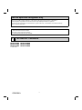
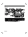
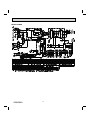
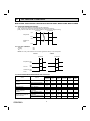
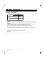
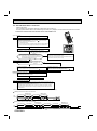
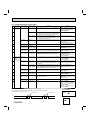
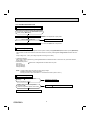
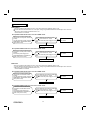
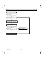
M How to check miswiring and serial signal error
NOTE: Refer to the indoor unit service manual.
Turn OFF the power supply.
Is there rated voltage in the power supply?
Yes
Check the power supply.
No
Turn ON the power supply.
Is there rated voltage between the outdoor terminal block S1 and S2?
Yes
No
Check the wiring.
Press EMERGENCY OPERATION switch once.
Does the left lamp of OPERATION INDICATOR
lamp light up? <Confirmation of the power to
the indoor unit>
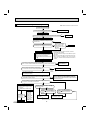
Yes
Is serial signal error indicated 6 minutes later?
No
No
Yes
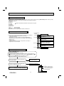
A
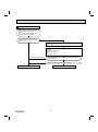
Turn OFF the power supply.
Check once more if the indoor/outdoor
B connecting wire is not miswiring.
Bridge the outdoor terminal block S2 and
S3. 1
Is there any miswiring,
poor contact, or wire
disconnection of the
indoor/outdoor connecting wire?
No
Yes
Correct them.
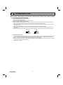
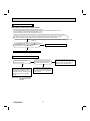
1. Miswiring may damage indoor electronic control P.C.
board during the operation.
Be sure to confirm the wiring is correct before the operation starts.
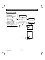
3. Be sure to check this within 3 minutes after turning ON.
After 3 minutes, LED blinks 6 times. Even when the
inverter P.C. board is normal, LED blinks 6 times after 3
minutes.
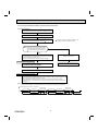
Turn ON the power supply.
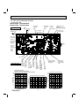
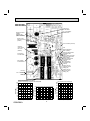
Is the bus-bar voltage of the inverter P.C. board normal?
(Refer to "TEST POINT DIAGRAM AND VOLTAGE" in the outdoor service manual.)
No
Check of power supply.
(Refer to the outdoor
service manual.)
Yes
Does the LED on the inverter P.C. board repeat
"3.6-second-OFF and 0.8-second-ON quick blinking"? 3
Yes
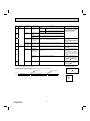
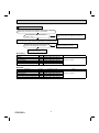
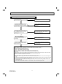
Turn OFF the power supply.
Remove the bridge between the outdoor terminal block S2 and S3.
Turn ON the power supply.
Is there rated voltage between the indoor terminal block S1 and S2?
<Confirmation of power voltage>
No
(Lighted
or not
lighted)
No
Yes
Is there amplitude of 10 to 20 VDC between the indoor terminal block
S2 and S3? <Confirmation of serial signal>
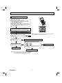
A
• Turn OFF inverter-controlled lighting
equipment.
• Turn OFF the power supply and then
turn ON again.
• Press EMERGENCY OPERATION
switch.
Is serial signal
error indicated 6
minutes later?
Yes
B
OBH584A
• Reinstall
either the unit
or the light
away from
each other.
• Attach a filter
No on remote
control receiving section
of the indoor
unit.
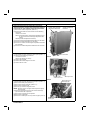
Replace the inverter P.C. board . 2
2. Be careful of the residual voltage of
smoothing capacitor.
Check the wiring
If there are any error of the indoor/outdoor connecting wire:
such as the damage of the wire, intermediate connection,
and/or poor contact to the terminal block, replace the indoor/
outdoor connecting wire.
No
Yes
Is there 2 VDC or less between CN202
(+)
and JPG (GND)(-) on the indoor electronic
control P.C. board?
No
Yes
Is there 2 VDC or less between
CN202A
(+) and JPG (GND)(-)
on the indoor electronic control P.C.
board?
No
Yes
Replace the indoor power
P.C. board.
39
Is there 2 VDC or less between
CN202
(+) and JPG (GND)(-) on
the indoor electronic control P.C.
board?
No
Replace the indoor electronic control P.C. board.
Yes