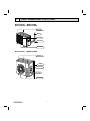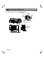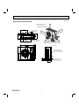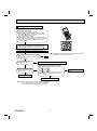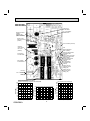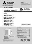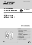
1
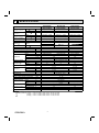
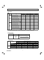
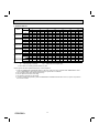
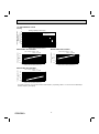
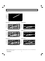
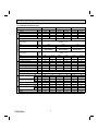
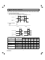
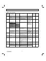
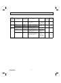
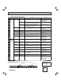
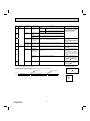
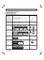
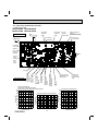
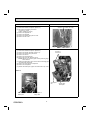
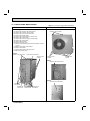
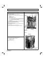
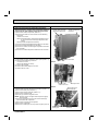
10-3. TROUBLESHOOTING CHECK TABLE
No.
1
Symptom
Outdoor unit
does not operate.
Abnormal point/
Condition
1-time flash every Outdoor power sys2.5 seconds
tem
Condition
LED indication
Remedy
• Reconnect connector of compressor.
• Refer to 10-5. "How to check
inverter/compressor".
• Check stop valve.
Outdoor thermistors Discharge temperature thermistor, fin temperature thermistor, • Refer to 10-5. "Check of outdoor
defrost thermistor, P.C. board temperature thermistor, outdoor thermistors".
heat exchanger temperature thermistor or ambient temperature thermistor shorts or opens during compressor running.
2
Overcurrent protection cut-out operates 3 consecutive times
within 1 minute after the compressor gets started.
6-time flash
2.5 seconds OFF
Outdoor control sys- Nonvolatile memory data cannot be read properly.
tem
(The left lamp of the OPERATION INDICATOR lamp on the
indoor unit lights up or flashes 7-time.)
Serial signal
The communication fails between the indoor and outdoor unit
for 3 minutes.
Stop valve/
Closed valve
Outdoor unit
(Other abnormality)
Closed valve is detected by compressor current.
Outdoor unit is defective.
6
11-time flash
2.5 seconds OFF
14-time flash
2.5 seconds OFF
• Refer to 10-2.2. "Flow chart of the
detailed outdoor unit failure mode
recall function".
7
16-time flash
2.5 seconds OFF
4-way valve/
Pipe temperature
The 4-way valve does not work properly.
The indoor coil thermistor detects an abnormal temperature.
• Refer to 10-5. "Check of R.V.
coil".
• Replace the inverter P.C. board.
17-time flash
2.5 seconds OFF
Outdoor refrigerant
system abnormality
A closed valve and air trapped in the refrigerant circuit are
detected based on the temperature sensed by the indoor and
outdoor thermistors and the current of the compressor.
• Check for a gas leak in a
connecting piping etc.
• Check the stop valve.
• Refer to 10-5. “Check of outdoor
refrigerant circuit”.
'Outdoor unit 2-time flash
2.5 seconds OFF
stops and
restarts 3
minutes later'
is repeated.
3-time flash
2.5 seconds OFF
Overcurrent protection
Large current flows into the power module (IC700) (FH09/12)/ • Reconnect connector of compressor.
IGBT module (IC700) (FH15).
• Refer to 10-5. "How to check
inverter/compressor".
• Check stop valve.
Discharge temperature overheat
protection
Temperature of discharge temperature thermistor exceeds
241°F (116°C), compressor stops. Compressor can restart if
discharge temperature thermistor reads 212°F (100°C) or less
3 minutes later.
Temperature of the fin temperature thermistor on the heat sink
exceeds 167 ~ 187°F (75 ~ 86°C) (FH09/12)/167 ~ 176°F
(75 ~ 80°C) (FH15) or temperature of P.C. board temperature
thermistor on the inverter P.C.board exceeds 162 ~ 185°F (72
~ 85°C) (FH09/12)/158 ~ 167°F (70 ~ 75°C) (FH15).
• Check refrigerant circuit and refrigerant amount.
• Refer to 10-5. "Check of LEV".
Indoor coil thermistor exceeds 158°F (70°C) in HEAT mode.
Defrost thermistor exceeds 158°F (70°C) in COOL mode.
• Check refrigerant circuit and refrigerant amount.
• Check stop valve.
• Reconnect connector of compressor.
• Refer to 10-5. "How to check
inverter/compressor".
3
4
5
8
9
10
4-time flash
2.5 seconds OFF
Fin temperature
/P.C. board temperature thermistor
overheat protection
12
5-time flash
2.5 seconds OFF
High pressure protection
13
8-time flash
2.5 seconds OFF
The waveform of compressor current is distorted.
Compressor synchronous abnormality
10-time flash
2.5 seconds OFF
Outdoor fan motor
11
14
15
12-time flash
2.5 seconds OFF
13-time flash
2.5 seconds OFF
Each phase current
of compressor
DC voltage
Outdoor fan has stopped 3 times in a row within 30 seconds
after outdoor fan start-up.
Each phase current of compressor cannot be detected normally.
DC voltage of inverter cannot be detected normally.
16
NOTE: 1. The location of LED is illustrated at the right figure. Refer to 10-6.1.
2. LED is lighted during normal operation.
• Replace inverter P.C. board.
• Check connection between the inverter P.C. board and the relay P.C.
board. (FH15)
• Refer to 10-5. "How to check
miswiring and serial signal error.
• Check stop valve.
• Check around outdoor unit.
• Check outdoor unit air passage.
• Refer to 10-5. "Check of outdoor
fan motor".
• Refer to 10-5.
fan motor.
• Refer to 10-5.
P.C. board.
"Check of outdoor
"Check of inverter
• Refer to 10-5. "How to check
inverter/compressor".
• It occurs with following case.
Instantaneous power voltage drop.
(Short time power failure) (FH15)
• Refer to 10-5. "Check of power
supply". (FH15)
• Refer to 10-5. "How to check inverter/compressor".
Inverter P.C. board
MUZ-FH09/12NA(H)
The flashing frequency shows the number of times the LED blinks after every 2.5-second OFF.
(Example) When the flashing frequency is “2”.
0.5-second ON
0.5-second ON
Flashing →
LED
ON
OFF
2.5-second OFF
MUZ-FH15NA(H)
2.5-second OFF
Flashing
→
OBH584A
28
LED