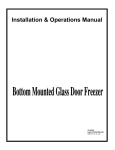
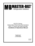
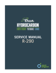
1
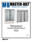
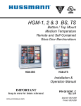
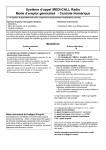
Installation & Operations Manual for BMG-HGP & BMG-SLP Model Bottom Mounted Full-Length Glass Door Refrigerator Merchandisers Sollatek controller Rev. 08-09-13 2 TABLE OF CONTENTS INTRODUCTION..4 STORE CONDITIONS........4 WARNING LABELS AND SAFETY INSTRUCTIONS......5 PRE-INSTALLATION INSTRUCTIONS........................6 Inspection for Shipping Damage..6 INSTALLATION INSTRUCTIONS.6 General Instructions...6 Mechanical .....6 Electrical......7 Temperature Control ....7 Leg.......8 Doors..........8 Grill..........8 SERVICE INSTRUCTIONS .9 TEMPERATURE CONTROL AND FAN MOTOR REPLACEMENT.10 FINAL CHECK LIST..10 PARTS LIST...11 ACCESSORIES. ...11 SALE AND DISPOSAL .12 WIRING DIAGRAM ....13-14 3 INTRODUCTION This manual contains important instructions for installing, using, and servicing a BMG-Plus case. A parts list is included with this manual. Read all these documents carefully before installing or servicing your equipment. STORE CONDITIONS The BMG-Plus cases are designed to operate in the controlled environment of an air-conditioned store. The store temperature should be at or below 75°F and a relative humidity of 55% or less. At higher temperature or humidity conditions, the performance of these cases may be affected and the capacity diminished. The BMG-Plus should not be positioned where it is directly exposed to rays of sun or near a direct source of radiant heat or airflow. This will adversely affect the case and will result in poor performance. If this case is to be located against a wall, there should be at least 4” space between the wall and the back of the case. This space will allow for the circulation of air behind the case, which will prevent condensation on the exterior surfaces. NOTICE Read this manual before installing your cabinet. Keep the manual and refer to it before doing any service on the equipment. Failure to do so could result in personal injury or damage to the cabinet. DANGER Improper or faulty hook-up of electrical components on the refrigeration units can result in severe injury or death. All electrical wiring hook-ups must be done in accordance with all applicable local, regional or national standards. NOTICE Installation and service of the refrigeration and electrical components of the cabinet must be performed by a refrigeration mechanic and/or a licensed electrician. The portions of this manual covering refrigeration and electrical components contain technical instructions intended only for persons qualified to perform refrigeration and electrical work. This manual cannot cover every installation, use or service situation. If you need additional information, call or write Customer Service Department. 4 WARNING LABELS AND SAFETY INSTRUCTIONS This symbol is the safety-alert symbol. When you see this symbol on your cabinet or in this manual, be alert to the potential for personal injury or damage to your equipment. Be sure you understand all safety messages and always follow recommended precautions and safe operating practices. NOTICE TO EMPLOYERS You must make sure that everyone who installs, uses or services your cabinet is thoroughly familiar with all safety information and procedures. Important safety information is presented in this section and throughout the manual. The following signal words are used in the warnings and safety messages: DANGER: Severe injury or death will occur if you ignore the message. WARNING: Severe injury or death can occur if you ignore the message. CAUTION: Minor injury or damage to your cabinet can occur if you ignore the message. NOTICE: This is important installation, operation or service information. If you ignore the message, you may damage your cabinet. The warning and safety labels shown throughout this manual are placed on your cabinet at the factory. Follow all warning label instructions. If any warning or safety labels become lost or damaged, call your customer service department at (800) 684-8988 for replacements. CAUTION! GROUND REQUIRED FOR SAFE OPERATION This label is located on top of the electrical control label and on the wiring channel. This label is attached to the cabinet power cord on models with a power cord. 5 PRE-INSTALLATION INSTRUCTIONS INSPECTION FOR SHIPPING DAMAGE You are responsible for filing all freight claims with the delivering truck line. Inspect all cartons and crates for damage as soon as they arrive. If damage is noted to shipping crates or cartons or if a shortage is found, note this on the bill of lading (all copies) prior to signing. If damage is discovered when the cabinet is uncrated, immediately call the delivering truck line and follow up the call with a written report indicating concealed damage to your shipment. Ask for an immediate inspection of your concealed damage item. Crating material must be retained to show the inspector from the truck line. INSTALLATION INSTRUCTIONS GENERAL INSTRUCTIONS 1. sure the equipment is properly installed by competent service people. 2. Keep the equipment clean and sanitary so it will meet your local sanitation codes. Clean the cabinet with a mild detergent and water, then rinse. 3. Rotate your stock so that older stock does not accumulate. This is especially important for iceream. A "First-In, First-Out" rotation practice will keep the products in good salable condition. 4. Do not place product in the case when it is soft or partially thawed. Also, product should not be put in the case for at least 6 hours after it is started. 5. Stock cases as quickly as possible, exposing only small quantities to store temperatures for short periods of time. 6. When replacing burned out light bars, be sure that the electrical power to the lighting circuit is turned off. NOTICE TO STORE OWNERS / MANAGERS Moisture or liquid around or under the cabinet is a potential slip/fall hazard for persons walking by or working in the general area of the cabinet. Any cabinet malfunction or housekeeping problem that creates a slip/fall hazard around or under the cabinet should be corrected immediately. If moisture or liquid is observed around or under a Master-Bilt cabinet, an immediate investigation should be made by qualified personnel to determine the source of the moisture or liquid. The investigation should determine if the cabinet is malfunctioning or if there is a drainpipe leaking. MECHANICAL Remove front grille and check refrigeration lines to see that they are free (not touching each other or compressor). Spin condenser fan blade to see that it is free. The compressor is hermetic, it is internally spring mounted and ready to run. Remove cabinet from crate base and slide into location. Cabinet must be level from side to side and front to back for correct draining of coil pan and for self-closing doors to operate correctly. Allow minimum of 4” between back of cabinet and wall and between top of cabinet and ceiling for proper condensing unit air circulation. To comply with Sanitation requirements the cabinet must be mounted on legs (6” high min.) or casters or the base must be sealed to the floor (BMG) with an N.S.F. listed silicone sealant. Hang provided NSF Listed thermometer at front of top shelf unless cabinet provided with electronic control. 6 ELECTRICAL WARNING Before servicing electrical components in the case or the doors or door frames make sure all power to case is off. Always use a qualified technician. Check voltage and amps drawn to determine proper line and fuse or circuit breaker size. Check power supply for low voltage. If voltage reads “120” with no load, and it drops below “100 or less” when the compressor tries to start, it is an indication of too small supply wiring or too long to run. It is recommended that a separate circuit be run for each cabinet to prevent another appliance blowing the fuse or breaker, causing loss of product. IMPORTANT This cabinet is pre-wired internally for 120-volt circuits. “Tapping” or feeding the 115-volt circuit from 230-volt supply may result in overloaded circuit breakers or blown fuses and damage to electrical system, thereby voiding the warranty. The cabinet should be grounded. Number indicator TEMPERATURE CONTROLLER Temperature Control The cabinet has a temperature control that is adjustable from # 0 (warmest setting) to # 9 (coldest setting). The controller isaccessible at the venturi inside the cabinet. Temperature Control 7 LEG / CASTER INSTALLATION 1. Screw legs / casters tightly into mounting holes under the front and back rail bases. SWING DOORS Leveling Adjustment The cabinet have Anthony glass doors that are equipped with a patented TorqueMaster hinge system. The doors are easily adjusted using a flathead screwdriver (Figure 3). Torque Adjustment Figure 3 GRILL To remove bottom grill, unscrew the 2 screws on the bottom for the grill then drop the grill down from the key-slot hole and pull out. (See Figure 4) Figure 4 Screw Screw 8 SERVICE INSTRUCTIONS 1. High head pressure and high back pressure: A. Condenser coil clogged or restricted B. Condenser fan motor defective. C. Air discharge in rear of cabinet restricted. 2. Low back pressure and low head pressure: A. Restriction in system. B. Refrigerant undercharged. C. Leak in system 3. Pressure normal – cabinet warm: A. Coil blocked with frost (see #4). B. Refrigerant undercharged. C. Control set too warm. 4. Cabinet not cycling – coil blocked with frost: A. Defective temperature controller. B. Refrigerant overcharged. C. Location too hot. D. Condenser clogged. E. Condenser fan motor defective. 5. Compressor starts and runs – but cycles on overload: A. Low voltage B. Relay defective. C. Overload defective. D. High head pressure (see #1). 9 TEMPERATURE CONTROL AND FAN MOTOR REPLACEMENT Before making any change, technician should: 1. Disconnect power to the cabinet 2. Remove screws from venturi and pull down To change fan motor – disconnect fan motor leads – remove screws from fan guards and motor mounts. To change a temperature control – pull off the control knob and remove screws from the control – unplug the control leads and replace with a new control – put screws back in control and press on control knob. FINAL CHECK LIST A. Check operating pressures. B. Check electrical requirements of unit to supply voltage. C. Set temperature control for desired temperature range. (factory recommended @ #6) D. Check sight glass for proper refrigerant charge (if provided) E. Check condensing unit for vibrating or rubbing tubing. Dampen and clamp as required. 10 PARTS LIST Use this chart when ordering replacement parts for your BMG Plus cabinets. Always Advise Cabinet Serial Number When Ordering Parts BMG-23-HGP BMG-27-HGP BMG-48-HGP BMG-48-SLP BMG-74-HGP BMG-74-HGP LED Light Bar (Single) 23-01835 23-01835 NA 23-01835 23-01839 (2)23-01837 LED Light Bar (Double) NA NA 23-01833 23-01833 Light Switch 23-50793 23-50793 23-50793 23-50793 23-50793 23-50793 Capillary Tube 11-01917 11-01917 11-01919 11-01919 11-01918 11-01918 Evaporator Coil 07-14083 07-14083 07-14086 07-14086 07-14084 07-14084 Evaporator Fan Blade 15-13106 15-13106 15-13106 15-13106 15-13106 15-13106 Evaporator Fan Motor 13-13181 13-13181 13-13181 13-13181 13-13181 13-13181 Evaporator Fan Guard 25-01324 25-01324 25-01324 25-01324 25-01324 25-01324 Compressor NA NA NA NA 03-15357 03-15357 Condenser Coil NA NA NA NA 07-14088 07-14088 Condenser Fan Motor NA NA NA NA 13-13101 13-13101 Condenser Fan Blade NA NA NA NA 15-13093 15-13093 Condensing Unit 01-01876 01-01876 01-01877 01-01877 NA NA Drier 09-09864 09-09864 09-09864 09-09864 09-09864 09-09864 Temperature Control 19-14239 19-14239 19-14239 19-14239 19-14239 19-14239 Thermometer 44-00963 44-00963 44-00963 44-00963 44-00963 44-00963 Door - LH Door - RH Pilaster 33-01408 33-01408 33-01408 33-01408 33-01408 33-01408 Pilaster Clip 33-01011 33-01011 33-01011 33-01011 33-01011 33-01011 Wall Guard 25-01376 25-01376 25-01376 25-01376 25-01376 25-01376 Shelf (Sides) 33-01812 33-01807 33-01805 33-01805 33-01805 33-01805 Shelf (Middle) NA NA NA NA 33-01807 33-01807 Accessories Description Casters (4) 3” Diameter Casters (6) 3” Diameter Legs 6” BMG-23, 27-HGP BMG-48-HGP, SLP A200-11140 A200-11140 A200-11170 A200-11170 BMG-74-HGP, SLP A212-11140 A212-11170 11 SALE AND DISPOSAL OWNER RESPONSIBILITY If you sell or give away your cabinet; you must make sure that all safety labels and the Installation - Service Manual are included with it. If you need replacement labels or manuals, factory will provide them free. Contact the customer service department at (800) 684-8988. The customer service department should be contacted at the time of sale or disposal of your cabinet so records may be kept of its new location If you sell or give away your cabinet and you evacuate the refrigerant charge before shipment, factory recommends that the refrigerant charge be properly recovered in compliance with section 608 of the Clean Air Act effective November 1995 and in accordance with all applicable local, regional, or national standards. 12 13 14 Customer Service/Warranty Parts Phone: 800-684-8988 Fax: 866-882-7629 Email: [email protected]