1
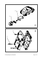
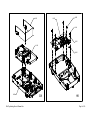
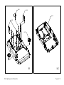
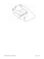
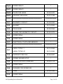
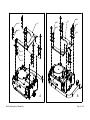
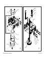
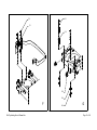
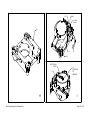
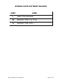
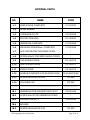
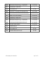
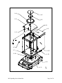
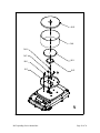
Service Manual
Bel Toploading Balances
Binary
Milligram
Centigram
Decigram
Classic
Analytical
Intelligent Weighing Technology serves the scale industry in the USA, Canada, Central and South America. We
provide competitive pricing on a co mplete range of scales, from floor scales to laboratory balance, load cells for
spare parts and scale manufacturing along, with other specialist weighing and testing equipment.
Intelligent Weighing Technology has more than 50 years of experience in the scale business, both in the USA and
worldwide. With contacts in over 50 countries including the USA, we provide you with the weighing equipment you
need.
5528 Everglades Street, Suite B
Ventura, CA 93003
Phone: (805) 642-3034
Fax: (805) 642-4034
Mobile: (805) 444-5657
Toll Free: (866) 920-3000
[email protected]
www.intelligentwt.com
BEL ENGINEERING
SERVICE
MANUAL
TOPLOADING BALANCES
JANUARY - 2004
REV. 1.0P
Note!
The power supply for Bel balances is 120 VAC input and 24VAC
output.
All analytical Bel balances have a power supply conditioner
fitted to ensure accurate weighing results.
BAL ANCE PARTS
S HEET
NO.
NAME
AK
K -1
EXTERNAL V ERSION OF BOARD
"ALINT REV4-B"
/
AK
K -2
AC ADAPTER
/
BK
K -3
BK
K -4
CK
K -5
COVER
CK
K -6
DISPLAY
/
CK
K -7
SCREW M3x6 FOR DISPLAY FIXING
/
CK
K -8
KEYBOARD
/
CK
K -9
SCREW REGULATOR CAP
DP 500
CK
K-1 0
COLUMNS CAP
DP 562
CK
K-1 1
SPIRIT LEVEL
/
DK
K-1 2
CONNECTOR RS 232
/
DK
K-1 3
CONNECTOR AL EXT LS
/
EK
K-1 4
INTERNAL VERSION OF BOARD
"ALINT REV4-B"
/
EK
K-1 5
SCREW M3x6 FOR BOARD FIXING
FK
K-1 6
SCREW M5x14 FOR ENBLOCK FIXING
/
FK
K-1 7
WASHER FOR SCREW M5
/
FK
K-1 8
SCREW M4x14 FOR ENBLOCK SHIELD
FIXING
/
GK
K-1 9
ENBLOCK
/
SCREW M4x45 FOR BALANCE
CLOSING
SCREW M4x25 FOR BALANCE
CLOSING
Bel Toploading Service Manual.doc
CODE
/
/
02-90-0399
Page 3 of 36
GK
K-2 0
ENBLOCK SHIELD
02-01-0368
GK
K-2 1
SPACER FOR ENBLOCK
02-07-0363
HK
K-2 2
BOARD "BIL 2407A REV1 6K"
Mod. 0,1g / 0,01g / 0,001g
/
HK
K-2 3
SCREW M3x6 FOR BOARD FIXING
/
HK
K-2 4
SCREW M3x6 FOR SIGNAL RESISTOR
FIXING
/
HK
K-2 5
PLASTIC WASHER FOR SCREW M3
/
HK
K-2 6
MICA
/
IK
K-2 7
ADJUSTABLE FOOT
/
IK
K-2 8
HOOK CAP
IK
K-2 9
CAP FOR HOLE CLOSING
LK
K-3 0
BASE
Bel Toploading Service Manual.doc
SP 1000
/
02-90-0398
Page 4 of 36
K-1
K-2
BK
K-3
K-4
AK
Bel Toploading Service Manual.doc
Page 5 of 36
K-11
K-10
K-12
K-8
K-9
K-13
K-5
K-6
K-7
CK
Bel Toploading Service Manual.doc
DK
Page 6 of 36
K-14
K-16
K-17
K-18
K-15
EK
Bel Toploading Service Manual.doc
FK
Page 7 of 36
K-20
K-22
K-23
K-24
K-25
K-19
K-26
K-21
Bel Toploading Service Manual.doc
GK
HK
Page 8 of 36
K-28
K-29
K-30
K-29
K-27
IK
Bel Toploading Service Manual.doc
LK
Page 9 of 36
W EIGHING CELL ENBLOCK FOR "MARK" BALANCES
0,1g / 0,01 / 0,001g RESOLUTION
SHEET
NAME
A
TOP PARALLEL GUIDE COMPLETE
B
BOTTOM PARALLEL GUIDE COMPLETE
CM
MOVING PILLAR COMPLETE FOR 0,1g / 0,01g
CN
MOVING PILLAR COMPLETE FOR 0,001g
D
MAGNETIC GROUP
E
LEVEL AND COIL COMPLETE
F
OPTICAL GROUP COMPLETE
G
REGULATORS FOR CORNER ERROR
H
W EIGHING CELL ENBLOCK
I
DETAIL OF OPTICAL GROUP AND SENSOR
CABLE
Bel Toploading Service Manual.doc
Page 10 of 36
Bel Toploading Service Manual.doc
Page 11 of 36
PARTICULARS CELL ENBLOCK 0,1g / 0,01g / 0,001g
NO.
NAME
CODE
A-1
TOP PARALLEL GUIDE
A-2
SCREW M4x10
/
A-3
WASHER FOR SCREW M4
/
A-4
FLAT SPRING LEF05 0.12
02-08-0258
A-5
SCREW M4x6
********
*****************************************************
02-06-0074
/
********************
B-1
BOTTOM PARALLEL GUIDE
02-06-0075
B-2
SCREW M4x10
/
B-3
WASHER FOR SCREW M4
/
B-4
FLAT SPRING LEF05 0.12
02-08-0258
B-5
SCREW M4x6
/
********
*****************************************************
CM -1
MOVING PILLAR
02-06-0071
CM -2
VERTICAL FLAT SPRING LT1 0.12
02-50-0263
CM -3
SPACER FOR VERTICAL FLAT SP. 1mm.
02-02-0417
CM -4
SPACER FOR VERTICAL FLAT SP. 5mm.
02-07-0246
CM -5
PLATE FOR V. SPRING CLAMPING
02-02-0118
CM -6
SCREW M4x10
Bel Toploading Service Manual.doc
********************
/
Page 12 of 36
CM -7
WASHER FOR SCREW M4
/
CM -8
CONE 6K PF
CM -9
SCREW M5x10
/
CM -10
WASHER FOR SCREW M5
/
CM -11
PLATE FOR CONE
02-02-0306
CM -12
SPACER FOR VERTICAL FLAT SP. 0,5mm.
02-02-0418
CM -13
SCREW M4x22
CM -14
PLATE FOR HOOK
02-04-0410
CM -15
SPACER FOR HOOK
02-07-0169
CM -16
SCREW M4x16
********
*****************************************************
02-04-0309
/
/
********************
CN-1
MOVING PILLAR
02-06-0071
CN-2
VERTICAL FLAT SPRING LT05 0.09
02-50-0261
CN-3
SPACER FOR VERTICAL FLAT SP. 1mm.
02-02-0417
CN-4
SPACER FOR VERTICAL FLAT SP. 5mm.
02-07-0246
CN-5
PLATE FOR V. SPRING CLAMPING
02-02-0118
CN-6
SCREW M4x12
/
CN-7
WASHER FOR SCREW M4
/
CN-8
CONE
CN-9
SCREW M5x10
/
CN-10
WASHER FOR SCREW M5
/
CN-11
PLATE FOR CONE
Bel Toploading Service Manual.doc
02-04-0092
02-02-0306
Page 13 of 36
CN-12
SCREW M4x16
/
CN-13
SCREW M4x18
/
CN-14
PLATE FOR HOOK
02-04-0410
CN-15
SPACER FOR HOOK
02-07-0169
********
*****************************************************
********************
D-1
MAGNETIC CIRCUIT
02-09-0065
D-2
MAGNET
02-14-0063
D-3
POLE SHOE
02-90-0064
D-4
COVER FOR MAGNETIC CIRCUIT
02-02-0072
D-5
SCREW M3x6
/
D-6
SCREW M5x8
/
D-7
ELECTRICAL PLATE AND SENSOR
/
********
*****************************************************
********************
LEVEL TYPE 0.1
02-12-0054
LEVEL TYPE 0.01
02-12-0055
E-2
SUPPORT FOR COIL
02-04-0057
E-3
SCREW M3 END-STOP
E-4
PLATE FOR COIL CLAMPING
E-5
SCREW M3x6
/
E-6
WASHER FOR SCREW M3
/
E-7
FLAG
E-8
SCREW M2x4
E-1
Bel Toploading Service Manual.doc
/
02-02-0119
02-90-0265
/
Page 14 of 36
E-9
FLAT SPRING LEF05 0.10
E-10
SCREW M4x10
/
E-11
WASHER FOR SCREW M4
/
********
*****************************************************
02-08-0257
********************
F-1
OPTICAL GROUP COMPLETE
/
F-2
SCREW M3x12
/
********
*****************************************************
********************
G-1
SCREW FOR CORNER ERROR
02-15-0066
G-2
BUSH FOR CORNER ERROR
02-15-0067
G-3
HEXAGON NUT M4
/
G-4
WASHER FOR SCREW M4
/
G-5
SPRING FOR REGULATOR
02-16-0159
********
H-1
********
I-1
*****************************************************
********************
WEIGHING CELL ENBLOCK TYPE 0.1 / 0.01
01-05-0051
WEIGHING CELL ENBLOCK TYPE 0.1 / 0.01
02-05 0052
*****************************************************
CABLE
Bel Toploading Service Manual.doc
********************
/
Page 15 of 36
B-2
A-2
B-5
A-1
B-1
B-3
B-3
A-3
B-4
A-4
A-3
A-5
A
Bel Toploading Service Manual.doc
B
Page 16 of 36
CM-8
CM-9
CM-6
CM-10
CM-7
CM-11
CM-1
CM-15
CM-14
CM-5
CM-2
CM-4
CM-7
CM-3
CM
( 0,1g / 0,01g )
CM-13
CM-12
CN-8
CM-7
CM-16
CN-9
CN-10
CN-6
CN-7
CN-11
CN-1
CN-15
CN-14
CN-4
CN-5
CN-2
CN
( 0,001g )
CN-3
Bel Toploading Service Manual.doc
CN-7
CN-13
CN-7
CN-12
Page 17 of 36
E-5
D-4
E-6
E-8
D-5
E-7
E-4
E-1
D-6
D-3
D-2
E-10
E-3
D-7
E-9
D-1
D
Bel Toploading Service Manual.doc
E-11
E-2
E
Page 18 of 36
G-1
F-2
F-1
G-2
G-5
G-4
F
Bel Toploading Service Manual.doc
G-3
G
Page 19 of 36
LEFT
RIGHT
OPTICAL
GROUP
H-1
LEFT
I-1
RIGHT
ELECTRICAL
PLATE
I-1
H
Bel Toploading Service Manual.doc
I-2
(POSITION
OF
SENSOR)
I
Page 20 of 36
EXTERNA L PA RTS FOR " MARK" BALANCE S
S HEET
NAME
L
ANALY TIC AL BALANC E
M
BALANCE TYPE 0,1g / 0,01g
N
BALANCE TYPE 0,001g
Bel Toploading Service Manual.doc
Page 21 of 36
EXTERNAL PART S
NO.
NA ME
CODE
L -1
WIND SHIELD COMPLETE
01-20-0397
L -2
LEVEL BUBBLE
L -3
STAINLESS PLATE
02-02-0369
L -4
PROTECTION RING
02-15-0097
L -5
UNDERPAN COMPLETE
01-00-0088
L -6
WEIGHING PAN Ø80mm. COMPLETE
01-00-0095
L -7
CAP FOR PROTECTION RING FIXING
/
L -8
SCREW M4x12 FOR WIND SHIELD FIXING
/
L -9
TOP SLIDING DOOR
02-18-0370
L -1 0
SIDE SLIDING DOOR
02-18-0371
L -1 1
FRONT DOOR
02-18-0372
L -1 2
HANDLE COMPLETE FOR SLIDING DOOR
L -1 3
SCREW REGULATOR CAP
DP 500
L -1 4
COLUMNS CAP
DP 562
/
02-20-0387/0388
********
*****************************************************
********************
M -1
UNDERPAN FOR SQUARE PLATE 6K PF
02-02-0324
M -2
SCREW M5x10 FOR UNDERPAN FIXING
/
M -3
SQUARE PAN 6K PF
M -4
MOUSSE
M -5
SCREW REGULATOR CAP
Bel Toploading Service Manual.doc
02-09-0325
/
DP 500
Page 22 of 36
M -6
WEIGHING PAN Ø160mm. COMPLETE
M -7
UNDERPAN COMPLETE
M -8
COLUMNS CAP
M -9
SUPPORT COLUMN FOR SQUARE PAN
********
*****************************************************
01-00-0244
/
DP 562
02-07-0085
********************
N-1
BASE FOR WIND SHIELD
02-09-0305
N-2
UNDERPAN COMPLETE
01-00-0088
N-3
WEIGHING PAN Ø110mm. COMPLETE
01-00-0096
N-4
PLEXIGLASS WIND SHIELD Ø160x70
02-18-0420
N-5
COVER WIND SHIELD
02-09-0283
N-6
SCREW M4x10
/
N-7
COLUMNS CAP
DP 562
N-8
SCREW REGULATOR CAP
DP 500
Bel Toploading Service Manual.doc
Page 23 of 36
L-4
L-3
L-6
L-5
L-8
L-9
L-2
L-7
L-1
L-10
L-14
L-12
L-13
L-11
Bel Toploading Service Manual.doc
L
Page 24 of 36
M-6
M-5
M-7
M-8
M-3
M-2
M-4
M-1
M-9
M-5
M
Bel Toploading Service Manual.doc
Page 25 of 36
N-5
N-4
N-8
N-7
N-6
N-1
N-3
N-2
N
Bel Toploading Service Manual.doc
Page 26 of 36
Bel Engineering Service Notes.
Balances
Classic
Centigram
Binary
Decigram
Milligram
Analytical
Bel balances are calibrated and linearized in California prior to shipping, using Class 1 weights traceable to
NIST or Class M OIML weights traceable to OIML Europe.
Upon receipt they should only need calibtration to take account of local acceleration due to G factors.
The balances should always be placed on a solid, stable and vibration free surface and free from drafts and air
currents. Do not use balances in bright sunlight as this may set up uneven temperature changes in the unit.
When the unit is positioned correctly, power up the unit and for analytical or milligram balances, do not press
the “On/Off” button for at least 25 minutes.
Following the warm up period, press the “On/Off” button.
Decigram, Classic and Centigram balances can be used immediately, but correct use analytical balances
should remain turned on for at least 2 hours before calibration or use. Milligram balances should ideally be
allowed to stabilize for 30 minutes after turning on.
Corner Loading.
Corner Load Error.
Corner load error is adjusted by the use of two adjusters in top of beam. In most balances access can be
obtained via access holes in the top of the balance cover.
X
A
⊕
Display
B
⊕
P
O
O
OOO
Bel Toploading Service Manual.doc
A screw adjusts X-Y
B screw adjusts P-Q
If Y is + & X is - turn A clockwise etc.
Page 27 of 36
Q
Y
Calibration/Linearity.
In order to linearize the balance correctly, the balance should be allowed to warm up for at least 2 hours for
analytical balances and 30 minutes for milligram balances.
Press and keep pressing CAL then plug in the power supply. The scale displays the notional thermometer
reading and then 00000.
Press CAL three times.
Display reads “LIN”
Press PRINT
Display shows “ZERO”
Press CAL again (no weight on pan)
Displays LIN 1 & arrow at 2nd ZERO.
Load 1/3rd weight (See attached chart for linearity weights)
Press CAL when stable.
Displays LIN 2 & arrow on 3rd ZERO
Load 2/3rd weight
Press CAL when stable.
Displays LIN 3 & arrow on 4th ZERO
Load Full Weight.
Press CAL when stable
End by pressing “On/Off”.
Always recalibrate after LIN EARITY adjustment.
Bel Toploading Service Manual.doc
Page 28 of 36
Linearization Values for Bel Balances
Point Point Point
Model
Resolution (g) 1
2
3
Point
4
120A
150A
205A
0.0001
0.0001
0.0001
0
0
0
40
50
60
80
100
120
120
150
180
160
220
330
500
0.001
0.001
0.001
0.001
0
0
0
0
50
70
110
150
100
140
220
300
150
210
330
450
2040
2060
0.001/0.01
0.001/0.01
0
0
130
200
260
400
390
600
800
1000
1300
1700
2200
3100
3500
4100
0.01
0.01
0.01
0.01
0.01
0.01
0.01
0.01
0
0
0
0
0
0
0
0
250
300
400
500
700
1000
1100
1300
500
600
800
1000
1400
2000
2200
2600
750
900
1200
1500
2100
3000
3300
3900
2020
8055
6045
SSR
10000
4500
6500
8000
0.01/0.1
0.01/0.1
0.01/0.1
0
0
0
600
1700
1500
1200
3400
3000
1800
5100
4500
0.1/1 g
0.1
0.1
0.1
0
0
0
0
3300
1500
2000
2500
6600
3000
4000
5000
9900
4500
6000
7500
Bel Toploading Service Manual.doc
Page 29 of 36
K 12
0.1
0
4000
K 16
0.1
0
5000
K 20
0.1
0
K 30
0.1
0
6000
1000
0
8000
1000
0
1200
0
2000
0
1200
0
1500
0
1800
0
3000
0
Fault Finding on Bel Engineering Balances.
Test Points
TP-7 is Analog Ground
TP-8 is Digital Ground
Symptom: Display frozen 00000
1.
2.
3.
4.
5.
a.
b.
- No output
Check that all springs and flexures are intact and not bent or broken. If damaged, replace and
reassemble. Jigs are available on request for this purpose.
Check that Level (E1) is centered, i.e. moves up and down and when power is supplied to the balance,
the Level tries to return to the mid point.
If not centered, check power supply voltage, TP3 to TP7 (Analog Ground). Voltage must be 12 VDC or
more. (If not see Section a.).
If voltage at TP3 is correct, check voltage at TP4 to TP7. This should read = 12.5 VDC (if not see
Section b.). If this is OK, remove J6 connector and check with meter that resistance between coil
connections (see diagram I on page 19 of manual). Resistance between right and left should be 38-42
O. If not correct or no resistance, check connection from coil to optical group Board F1. Possible
cause is the gold wires connecting monoblock to the level are broken.
If none of the above, it is possible that the optical group itself has failed. Remove and replace.
If this measurement is not correct, remove J4 connector and check the output on U@-7812
Rectifier. This should be 12 volt. If not, remove and replace the power board.
If this measurement is not OK, remove J4 connector & check output on U3-7912 this should be =
12.5 volt. If not correct remove and replace the power board.
See drawing ALINT Rev. 4.
Optical Group
To check veracity of signal from optical group:
a.
With the pan fitted, but no load on pan (at rest), test between TP7 (ground) and TP6, the value should
be minus 3.3 volts minimum signal. (See FIG.1).
Bel Toploading Service Manual.doc
Page 30 of 36
Generally factory set for 1 volt reading, this will allow technicians to see a negative reading when the pan is
removed, rather than an underweight signal.
If the Signal shown is below minus 3.3 volts (See FIG.2)
b.
Apply full load to balance. Test between TP7 and TP6. It is important that the positive signal is 0.3 volts
or more.
(FIG 3 shows correct reading)
Bel Toploading Service Manual.doc
Page 31 of 36
(FIG 4 shows incorrect reading).
If either signal is not correct, change the resistance at 70.
No load, no negative signal, increase resistance.
Full load, no positive signal, decrease resistance.
Bel Toploading Service Manual.doc
Page 32 of 36
Note! on analytical balances, the balance should be returned to Intelligent Weighing Technology for fitting of
specialized resistances.
To check the clock speed of DSP.
Test between TP -7 and TP-13, you should be able to clearly see equal distances between signal values and 3.3
volts positive between signal values. If no signal Crystal Y1 is malfunctioning. (7.3728)
(FIG. 5 shows correct reading).
Test TP -7 to TP -12. Should show wide band on screen
(FIG. 6)
A thin band shows a malfunction
(FIG. 7).
Bel Toploading Service Manual.doc
Page 33 of 36
If the band is thin, change crystal Y2.
Test Thermometer Frequency to Analog to Digital converter.
Test TP-7 to TP-14.
(FIG. 8. shows correct signal).
Bel Toploading Service Manual.doc
Page 34 of 36
(See FIG. 9, showing bad or no signal. Possible cause is inverted signal wires on connections to magnet).
TP-7 to TP-16
Signal must be +5 VDC, if not, suspect U15 the rmometer is faulty.
TP-7 to TP-15
Signal should be +2.5 to 3 VDC, if not, suspect U16 thermometer is faulty.
TP-7 to TP-11
This is a reference voltage, it should be -7 VDC. If not, suspect U18 (Under Foam Insulator) is faulty.
Removal of Magnet
Remove top 3 screws from cover and remove. Remove the two wires from the base of the magnet
(note they must be reattached in the same order). Remove the three positioning grub screws and the
two inner ones (same threaded hole) and withdraw magnet from unit. Inspect and clean, then
Bel Toploading Service Manual.doc
Page 35 of 36
replace using 4 spacers to position the magnet in the exact middle of the unit only if you moved the
level arm.
If there is drift in the balance and it is always in one direction, then suspect that there is physical
damage to the sy stem. Start with magnet, then gold connecting wires, finally the flexure system.
Display
No Power to Display
Check power to jack plug, 24 VAC.
If no power or not correct voltage then replace the complete unit.
If the above are OK, connect meter to TP7 and TP2 (DC voltage) should read 5 volts ± 2% if not OK see
section “A” 1. If voltage is OK then check TP7 to TP1 should read 3.3 volts ± 2% If not OK see section
“A” 2
If OK then TP7 to TP5 should be 32-34 VDC (for display) See section A.1. If this is OK change the
display. Note! Be sure to order the same build # code as on the back of the display unit.
If the display has power but does not illuminate any segments when pushing the “on/off” switch, fit
new keyboard (K-8)
Section A.
A.1.
Change power supply board K-14. See ALINT Rev 4-B.
A.2.
Check TP-7 ground to regulator U8 LM-3940. Should read 5.0 VDC input and 3.3 VDC output. If
no output, change regultor or main board.
If none of the above cure the problem, change the main board. K-22 Bil 2407 A rev 1
It is possible for the optical group to cause interference and instability. Replace complete group.
Display Error Codes
Display shows
|_____|
Display shows
_____
|
Underweight Condition
Overweight Condition
|
Following power up and pressing “On/Off” display shows
-- -- means balance is not
stable. Check for interference, vibration, air currents. If OK remove top plate from magnet and clean.
Check that the lever is centered in the magnet and will return to the center when moved (power must
be connected). Finally, check flexures and vertical and horizontal springs for distortion or damage.
Poor Return To Zero
1.
2.
Check all flexures and vertical springs for damage or breakage and replace where
neccessary.
Remove magnet cover and clean. Check lever for physical interference.
Bel Toploading Service Manual.doc
Page 36 of 36