1
GCS16
GCS20
Corp. 0110−L6
Revised 12−2004
Service Literature
2 to 5 Ton
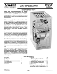
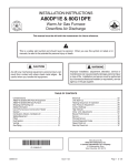
GCS16/GCS20 SERIES UNITS
GCS16/20 series units in the 2 to 5 ton (7.0 to 17.0 kW)
cooling size are packaged combination gas heat / dx cool
units designed for commercial applications. Gas heat sections are available with Lennox’ new tubular heat exchanger in 50,000, 75,000, 90,000 and 120,000 (14.7, 22.0, 26.4,
35.2 kW) Btuh input sizes.
Three phase GCS20 units manufatured April 2002 and later have a 12.0 seer rating. Revised specifications, electrical
data and blower data are included in this manual.
All GCS20 model units and GCS16−036 and −048 utilize a
scroll compressor. The scroll compressor offers high volumetric efficiency, quiet operation and the ability to start under system load. Continuous flank contact, maintained by
centrifugal force, minimizes gas leakage and maximizes efficiency. The motor is internally protected from excessive
current and temperature. GCS16−024, −030 and−060 models will be equipped with a reciprocating compressor. The
reciprocating compressor is hermetically sealed for trouble
free operation and long service life. Like the scroll, the reciprocating compressor has a built−in protection device
against excessive current and temperatures.
The GCS16/20 is designed to accept any of several different thermostat control systems with minimum field wiring.
Control options such as economizer, warm up kit, Honeywell T7300 control or Honeywell T8600 control are applicable. When installed, the controls become an integral part of
the unit wiring. Units are also equipped with a low voltage
pig tails to facilitate thermostat field wiring.
Information in this manual is for use by a qualified service
technician only. All specifications in this manual are subject
to change. Procedures outlined in this manual are represented as a recommendation only and do not supersede or
replace state or local codes.
WARNING
Refrigerant can be harmful if it is inhaled. Refrigerant
must be used and recovered responsibly.
Failure to follow this warning may result in personal
injury or death.
Page 1
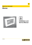
GCS16 SHOWN
WARNING
Electric shock hazard. Can cause injury
or death. Before attempting to perform
any service or maintenance, turn the
electrical power to unit OFF at disconnect switch(es). Unit may have multiple
power supplies.
ELECTROSTATIC DISCHARGE (ESD)
Precautions and Procedures
CAUTION
Electrostatic discharge can affect electronic
components. Take precautions during furnace
installation and service to protect the furnace’s
electronic controls. Precautions will help to
avoid control exposure to electrostatic discharge
by putting the furnace, the control and the technician at the same electrostatic potential.
Neutralize electrostatic charge by touching hand
and all tools on an unpainted unit surface, such
as the gas valve or blower deck, before performing any service procedure.
© 2001 Lennox Industries Inc.
Litho U.S.A.
Table of Contents
Introduction . . . . . . . . . . . . . . . . . . . . . . .
Specifications . . . . . . . . . . . . . . . . . . . . . .
Optional Accessories . . . . . . . . . . . . . . .
Electrical Data . . . . . . . . . . . . . . . . . . . . .
High Altitude . . . . . . . . . . . . . . . . . . . . . .
Blower Data . . . . . . . . . . . . . . . . . . . . . . .
I Application . . . . . . . . . . . . . . . . . . . . . . .
II Unit Components . . . . . . . . . . . . . . . . .
Control Box . . . . . . . . . . . . . . . . . . . .
Heating . . . . . . . . . . . . . . . . . . . . . . . .
Cooling . . . . . . . . . . . . . . . . . . . . . . . .
1
2
6
7
8
9
17
17
17
20
26
III Placement and Installation . . . . . . . . 29
IV Electrical Connections . . . . . . . . . . . . 29
V Start Up . . . . . . . . . . . . . . . . . . . . . . . . . 29
VI Refrgeration System Service Checks 31
VII Heating System Service Checks . . 32
VIII Indoor Blower Operation . . . . . . . . . 33
IX Maintenance . . . . . . . . . . . . . . . . . . . 35
X Accessories
. . . . . . . . . . . . . . . . . . . . 36
XI Wiring and Operation Sequence . . . 41
SPECIFICATIONS GCS16
GCS16−024−50
GCS16X−024−50
Model No.
Nominal Tonnage (kW)
Heating
Capacity
GCS16−030−75
GCS16X−030−75
2 (7.0)
2.5 (8.8)
3 (10.6)
Input − Btuh (kW)
50,000 (14.7)
75,000 (22.0)
90,000 (26.4)
Output − Btuh (kW)
40,000 (11.7)
60,000 (17.6)
72,000 (21.1)
lA.F.U.E.
LARI
Certified
Cooling
Ratings
80.0%
Cooling capacity − Btuh (kW)
23,200 (6.8)
Total unit watts
27,400 (8.0)
2670
10.00
EER (Btuh/Watts)
8.70
9.20
3 lbs. 3 oz. (1.45 kg)
Blower wheel nominal diameter x width − in. (mm)
4 lbs. 3 oz. (1.90 kg)
9 x 8 (229 x 203)
10 x 8 (254 x 203)
1/3 (249)
1/2 (373)
Net face area − sq. ft. (m2)
3.2 (0.30)
4.10 (0.38)
Tube diameter − in. (mm) & No. of rows
3/8 (9.5) − 2
Net face area
sq. ft. (m2)
15 (591)
Outer coil
8.70 (0.81)
Inner coil
Tube diameter − in. (mm) & No. of rows
−−−−
8.40 (0.78)
3/8 (9.5) − 1
3/8 (9.5) − 2
Fins per inch (m)
20 (787)
Diameter − in. (mm) & No. of blades
Condenser
Fan
4 lbs. 6 oz. (1.94 kg)
Motor horsepower (W)
Fins per inch (m)
Condenser
Coil
3850
10.10
80
Refrigerant Charge (HCFC−22)
Evaporator
E
t
Coil
35,400 (10.4)
3150
SEER (Btuh/Watts)
*Sound Rating Number (db)
Evaporator
Blower
GCS16−036−90
GCS16X−036−90
Air volume − cfm (L/s)
20 (508) − 4
2450 (1155)
2200 (1040)
Motor horsepower (W)
1/6 (124)
Motor watts
220
240
Gas Supply Connections fpt − in. (mm)
Recommended Gas Supply Pressure
in. w.c. (kPa)
1/2 (12.7)
Natural Gas
7 (1.7)
LPG/Propane
11 (2.7)
Condensate drain size mpt − in. (mm)
3/4 (19)
No. & size of cleanable polyurethane filters − in. (mm)
(1) 16 x 25 x 1 (406 x 635 x 25)
Net weight of basic unit − lbs. (kg)
350 (159)
373 (169)
Shipping weight of basic unit − lbs. (kg) 1 pkg
432 (196)
455 (206)
Electrical characteristics − (60hz)
208/230v − 1 phase
370 (168)
470 (213)
208/230v − 1 ph
208/230v, 460v or 575v − 3 ph
*Sound Rating Number in accordance with test conditions included in ARI Standard 270.
lAnnual Fuel Utilization Efficiency based on DOE test procedures and FTC labeling regulations.
LCertified in accordance with the USE certification program, which is based on ARI Standard 210/240: 95_F (35_F) outdoor air temperature and 80_F (27_C) db/67_F (19_C)
wb entering evaporator coil air.
Page 2
SPECIFICATIONS GCS16 CONT.
GCS16−048−75
GCS16X−048−75
Model No.
Nominal Tonnage (kW)
Heating
Capacity
GCS16−048−120
GCS16X−048−120
4 (10.1)
Input − Btuh (kW)
75,000 (22.0)
120,000 (35.2)
75,000 (22.0)
120,000 (35.2)
Output − Btuh (kW)
60,000 (17.0)
96,000 (28.1)
60,000 (17.0)
96,000 (28.1)
80.0%
Cooling capacity − Btuh (kW)
46,500 (13.6)
58,500 (17.1)
Total unit watts
4890
6570
SEER (Btuh/Watts)
10.35
10.00
9.5
8.90
EER (Btuh/Watts)
*Sound Rating Number (db)
82
Refrigerant Charge (HCFC−22)
Evaporator
Blower
5 lbs. 11 oz. (2.58 kg)
Blower wheel nominal diameter x width − in. (mm)
3/4 (560)
(m2)
5.30 (0.49)
6.20 (0.58)
Tube diameter − in. (mm) & No. of rows
3/8 (9.5) − 2
Fins per inch (m)
Net face area
sq. ft. (m2)
Condenser
Coil
15 (591)
Outer coil
14.30 (1.33)
Inner coil
Tube diameter − in. (mm) & No. of rows
5.90 (0.55)
13.70 (1.27)
3/8 (9.5) − 1.4
3/8 (9.5) − 2
Fins per inch (m)
20 (787)
Diameter − in. (mm) & No. of blades
Condenser
Fan
24 (610) − 4
Air volume − cfm (L/s)
3880 (1830)
Motor horsepower (W)
3770 (1780)
1/4 (187)
Motor watts
340
Gas Supply Connections fpt − in. (mm)
Recommended Gas Supply Pressure
in. w.c. (kPa)
7 lbs. 0 oz. (3.18 kg)
11−1/2 x 9 (292 x 229)
Motor horsepower (W)
Net face area − sq. ft.
Evaporator
Coil
GCS16−060−120
GCS16X−060−120
5 (17.6)
lA.F.U.E
LARI
Certified
Cooling
Ratings
GCS16−060−75
GCS16X−060−75
360
1/2 (12.7)
Natural Gas
7 (1.7)
LPG/Propane
11 (2.7)
Condensate drain size mpt − in. (mm)
3/4 (19)
No. & size of cleanable polyurethane filters − in. (mm)
(1) 20 x 25 x 1 (508 x 635 x 25)
Net weight of basic unit − lbs. (kg)
496 (225)
526 (239)
Shipping weight of basic unit − lbs. (kg) 1 package
605 (274)
635 (288)
Electrical characteristics − (60hz)
208/230v − 1 ph,
208/230v or
460v − 3 ph
208/230v − 1 ph,
208/230v, 460v or
575v − 3 ph
208/230v − 1 ph,
208/230v or
460v − 3 ph
208/230v − 1 ph,
208/230v, 460v or
575v − 3 ph
*Sound Rating Number in accordance with test conditions included in ARI Standard 270.
lAnnual Fuel Utilization Efficiency based on DOE test procedures and FTC labeling regulations.
LCertified in accordance with the USE certification program, which is based on ARI Standard 210/240: 95_F (35_F) outdoor air temperature and 80_F (27_C) db/67_F (19_C)
wb entering evaporator coil air.
Page 3
SPECIFICATIONS GCS20
GCS20
-024-50
GCS20
-030-75
GCS20
-036-90
2
2−1/2
3
Btuh
50,000
75,000
90,000
75,000
120,000
75,000
120,000
75,000
120,000
kW
14.7
22.0
26.4
22.0
35.2
22.0
35.2
22.0
35.2
Btuh
40,000
60,000
72,000
60,000
96,000
60,000
96,000
60,000
96,000
kW
11.7
17.6
20.5
17.6
28.1
17.6
28.1
17.6
28.1
ModelNo.
Nominal Tonnage
GCS20
−042−75
GCS20
−042−120
GCS20
−048-75
3−1/2
GCS20
−048-120
GCS20
-060-75
4
GCS20
-060-120
5
Input
Heating
Capacity
Output
lA.F.U.E.
80.0%
*Sound Rating Number (db)
LARI
Standard
210/240
Ratings
TotalCooling
Capacity
80
Btuh
kW
Total Unit Watts
30,400
33,600
41,000
48,000
58,000
7.2
8.9
9.8
12.0
14.1
17.0
2420
3140
3500
4165
4775
5985
11.3
11.30
11.00
9.8
10.1
9.7
5 lbs. 2 oz.
(2.32 kg)
7 lbs. 3 oz.
(3.26 kg)
7 lbs. 5 oz.
(3.32 kg)
11.00
10.2
9.70
9.60
4 lbs. 5 oz. 4 lbs. 10 oz. 4 lbs. 6 oz.
(2.0 kg)
(2.10 kg)
(3.02 kg)
Refrigerant Charge (HCFC-22)
Blower
in.
wheel nominal
wheelnominal
Evaporator
diameterx width mm
Blower
Motor output − hp (W)
Netfacearea− sq.ft. (m2)
82
24,600
SEER(Btuh/Watts)
EER (Btuh/Watts)
78
9x8
10 x 8
11−1/2 x 9
229 X 203
254 X 203
292 x 228
1/3 (249)
3.2 (0.30)
1/2 (373)
4.1 (0.38)
3/4 (560)
4.1 (0.38)
Evaporator Tubediameter− in.
(mm)&No.of rows
Coil
5.3 (0.49)
6.2 (0.58)
3/8(9.5) − 2
Finsperinch (m)
15 (590)
Outer Coil
8.7 (0.81)
Inner Coil
Condenser
Tube diameter− in. (mm)&No.
Coil
of rows
8.4 (0.78)
5.9 (0.55)
13.7 (1.27)
3/8 (9.5) − 2
3/8 (9.5) − 1.4
3/8 (9.5) − 2
Netface area
− sq.ft. (m2)
14.3 (1.33)
Finsperinch (m)
Diameter− in. (mm)&No.of
blades
Condenser Airvolume− cfm (L/s)
Fan
Motor output − hp (W)
Motorwatts
20 (787)
20(508) − 4
24 (610) − 4
2200(1040)
3880 (1830)
3770 (1780)
1/6 (124)
1/4 (187)
240
340
360
GasSupply Connectionsfpt− in. (mm)
1/2 (13)
Natural
RecommendedGas
SupplyPressure− wc.in. (kPa) LPG/Propane
7 (1.7)
11 (2.7)
Condensatedrainsizempt− in. (mm)
3/4 (19)
No. & size of cleanable polyurethane
filters − in. (mm)
(1) 16 x 25 x 1 (406 x 635 x 25)
Netweightofbasicunit− lbs. (kg)(1Pkg.)
406 (184)
494 (224)
527 (239)
541 (245)
Shipweightofbasicunit− lbs. (kg)(1Pkg.)
472 (214)
603 (274)
636 (288)
650 (295)
Electrical characteristics − 60 hertz
208/230v − 1 phase
208/230v
1ph
208/203v or
460v 3 ph
(1) 20 x 25 x 1 (508 x 635 x 25)
208/230v − 1 phase
208/230v − 1 phase
208/203v or 460v 3phase
lAnnual Fuel Utilization Efficiency based on DOE test procedures and FTC labeling regulations.
*Sound Rating Number in accordance with test conditions included in ARI Standard 270.
LCertified in accordance with the USE certification program, which is based on ARI Standard 210/240: 95_F (35_C) outdoor air temperature and 80_F (27_C) db/67_F (19.5_C) wb
entering evaporator air.
Page 4
SPECIFICATIONS GCS20
(manufactured April 2002 and later)
SPECIFICATIONS − GCS20
Heating
g
P f
Performance
GCS20-036-75
GCS20−048-75
GCS20−048-120
GCS20-060-75
GCS20-060-120
Input − Btuh (kW)
ModelNo.
75,000 (22.0)
75,000 (22.0)
120,000 (35.2)
75,000 (22.0)
120,000 (35.2)
Output − Btuh (kW)
60,000 (17.6)
60,000 (17.6)
96,000 (28.1)
60,000 (17.6)
96,000 (28.1)
80.0%
80.0%
80.0%
80.0%
80.0%
1/2
1/2
1/2
1/2
1/2
lA.F.U.E.
GasSupply Connectionsnpt − in.
Recommended Gas Supply Pressure 7 in. w.c. (1.7 kPa) 7 in. w.c. (1.7 kPa) 7 in. w.c. (1.7 kPa) 7 in. w.c. (1.7 kPa) 7 in. w.c. (1.7 kPa)
− Natural Gas
LPG/Propane 11 in. w.c. (2.7 kPa) 11 in. w.c. (2.7 kPa) 11 in. w.c. (2.7 kPa) 11 in. w.c. (2.7 kPa) 11 in. w.c. (2.7 kPa)
Cooling
Performance
Nominal Tonnage (kW)
3 (10.6)
4 (14.1)
4 (14.1)
5 (17.6)
5 (17.6)
35,200 (10.3)
50,000 (14.6)
50,000 (14.6)
59,000 (17.3)
59,000 (17.3)
3330
4545
4545
5765
5765
LSEER(Btuh/Watts)
12.40
12.70
12.70
12.00
12.00
EER (Btuh/Watts)
10.60
11.00
11.00
10.20
10.20
82
82
82
82
82
Refrigerant Charge (HCFC-22)
5 lbs. 2 oz.
(2.34 kg)
7 lbs. 14 oz.
(3.57 kg)
7 lbs. 14 oz.
(3.57 kg)
8 lbs. 8 oz.
(3.86 kg)
8 lbs. 8 oz.
(3.86 kg)
Netface area − sq.ft. (m2) Outer
Coil
14.3 (1.33)
14.3 (1.33)
14.3 (1.33)
14.3 (1.33)
14.3 (1.33)
Inner Coil
5.9 (0.55)
13.7 (1.27)
13.7 (1.27)
13.7 (1.27)
13.7 (1.27)
Tube diameter− in. (mm)
LCooling Capacity Btuh (kW)
Total Unit Watts
*Sound Rating Number (dB)
Condenser
Coil
Condenser
Fan
3/8 (9.5)
3/8 (9.5)
3/8 (9.5)
3/8 (9.5)
3/8 (9.5)
Number of rows
1.4
2
2
2
2
Finsperinch (m)
20 (787)
20 (787)
20 (787)
20 (787)
20 (787)
Motor horsepower (W)
1/4 (187)
1/4 (187)
1/4 (187)
1/4 (187)
1/4 (187)
340
360
360
360
360
Diameter− in. (mm)
24(610)
24 (610)
24 (610)
24 (610)
24 (610)
Numberof blades
4
4
4
4
4
Motorwatts
Airvolume− cfm (L/s)
Evaporator
Coil
3880(1830)
3770 (1780)
3770 (1780)
3770 (1780)
3770 (1780)
(m2)
5.3 (0.49)
6.2 (0.58)
6.2 (0.58)
6.2 (0.58)
6.2 (0.58)
Tubediameter− in. (mm)
3/8(9.5)
3/8(9.5)
3/8(9.5)
3/8(9.5)
3/8(9.5)
Netfacearea− sq.ft.
Numberof rows
2
3
3
3
3
Finsperinch (m)
15 (590)
14 (552)
14 (552)
14 (552)
14 (552)
3/4
3/4
3/4
3/4
3/4
Condensatedraincoupling sizenpt − in.
Evaporator
Blower
Filters
Shipping
Data
1/2 (373)
3/4 (560)
3/4 (560)
3/4 (560)
3/4 (560)
Wheelnominal diameterx width −
in. (mm)
Motor horsepower (W)
10 x 8
(254 X 203)
11−1/2 x 9
(292 x 228)
11−1/2 x 9
(292 x 228)
11−1/2 x 9
(292 x 228)
11−1/2 x 9
(292 x 228)
Cleanable, polyurethane − No. & size
− in.
(1) 20 x 25 x 1
(1) 20 x 25 x 1
(1) 20 x 25 x 1
(1) 20 x 25 x 1
(1) 20 x 25 x 1
mm
508 x 635 x 25
508 x 635 x 25
508 x 635 x 25
508 x 635 x 25
508 x 635 x 25
Netweightofbasicunit− lbs. (kg)
496 (225)
541 (245)
541 (245)
541 (245)
541 (245)
Ship.wt.ofbasicunit − lbs. (kg)1pkg.
603 (274)
650 (295)
650 (295)
650 (295)
650 (295)
208/203v − 3 ph
460v − 3 ph
208/203v − 3 ph
460v − 3 ph
208/203v − 3 ph
460v − 3 ph
208/203v − 3 ph
460v − 3 ph
208/203v − 3 ph
460v − 3 ph
Electrical characteristics (60 hz)
lAnnual Fuel Utilization Efficiency based on DOE test procedures and FTC labeling regulations.
*Sound Rating Number in accordance with test conditions included in ARI Standard 270.
LCertified in accordance with the USE certification program, which is based on ARI Standard 210/240: 95_F (35_C) outdoor air temperature and 80_F (27_C) db/67_F (19.5_C) wb
entering evaporator air.
Page 5
OPTIONAL ACCESSORIES GCS16/20
Model No.
Coil Guards PVC coated steel wire guards to protect outdoor coil
Standard equipment on GCS20 single phase units.
Cold Weather Kit (GCS16 Units Canada Only) Electric heater automatically
controls minimum temperature in gas burner compartment when temperature
is below 40_F (4_C). CGA certified to allow operation of unit down to −60_F
(−50_C)
Control Systems See pages 4−5 for complete listing.
Compressor Monitor (GCS16 Units Canada Only) Non-adjustable switch
(low ambient cut-out) prevents compressor operation when outdoor temperature is below 32°F (0°C).
Diffusers Aluminum grilles, large center grille, insulated Step-Down −
double deflecdiffuser box with flanges, hanging rings furnished, interior
tion louvers
recirtransition (even air flow), internally sealed (prevents recir
culation), adapts to T-bar ceiling grids or plaster ceilings − Flush − fixed
Net Weight
blade louvers
Economizer with Gravity Exhaust Dampers
3 Position
(Down Flow) Installs directly in cabinet,
(Down−Flow)
cabinet recirrecir
Fully Modulating
culated air dampers with pressure operated gravigravi
US
ty exhaust damper, formed, gasketed damper
Only
Indoor Filter
blades nylon bearings
blades,
bearings, 24v damper motor has
Outdoor Filter
adjustable
j
minimum position
p
switch,, electronic
di h
discharge
air
i sensor, adjustable
dj t bl outdoor
td
air
i enFully Modulating
thalpy control. Utilizes filter furnished with unit,
GCS16
filter rack will accept up to 2 in. (51 mm) filter.
Indoor Filter
units
Removable exhaust air hood and outdoor air inin
C
Canada
d
take hood with cleanable aluminum mesh filter.
Only
Outdoor Filter
Choice of economizer controls.
3 Position
Economizer Dampers (Horizontal) Installs diFully Modulating
rectly in cabinet, combination outdoor air and reUS
circulated air damper, formed, gasketed damper
Only
Indoor Filter
y
g , 24v damper
p motor has
blades,, nylon
bearings,
adjustable minimum position switch
switch, electronic
Outdoor Filter
discharge air sensor
sensor, adjustable outdoor air enFully Modulating
thalpy control. 1 in (25 mm) fiberglass filter fur
furGCS16
nished, filter rack will accept up to 2 in. (51 mm)
Indoor Filter
Units
filter outdoor air intake hood with aluminum mesh Canada
filter,
C
d
filter. Choice of economizer controls.
Outdoor Filter
Only
Enthalpy Control, Differential Used in conjunction with outdoor air enthalpy
control. Determines and selects which air has the lowest enthalpy. Return air
enthalpy sensor field installs in economizer damper section
Gravity Exhaust Dampers For use with EMDH16. Pressure operated assembly field installs in the return air duct adjacent to the economizer assembly. Includes bird screen. − Net Weight
Horizontal Filter Kit (GCS16 Units Canada Only) For horizontal applications,
painted steel cabinet with filter access, disposable, pleated fiber filter furnished,
see dimension drawing, No. and size of filter − Net Weight
Low Ambient Control Kit Units operate down to 30°F (−1°C) outdoor air temperature in cooling mode without any additional controls. Kit can be field
installed, enables unit to operate properly down to 0°F (−18°C).
LPG/Propane Kits − Conversion from Natural Gas to LPG/Propane
Roof Curb Power Entry Kit Allows power entry through roof mounting
frame, knockouts provided in roof frame, kit contains 1/2 in. (13 mm) x 40 in.
(1016 mm) armored conduit and installation hardware, two kits are required,
one for low voltage and one for high voltage. See Dimension Drawing
Roof Mounting Frame Nailer strip furnished, mates to unit, U.S. National
Roofing Contractors Approved, shipped knocked down. RMF16−41 may be
used on all sizes, with a slight unit overhang on GCS20−042, GCS16/20−048
and GCS16/20−060 units − Net Weight
NOTE (US Only) Sound Reduction Plate must be ordered separately for field
installation.
-024
−030
−036
LB−82199CF (47J23)
2 guards per order
65C03
See pages 4−5
T6−1469 (45F08)
RTD9−65 − 67 lbs. (30 kg)
FD9−65 - 37 lbs.(17 kg)
REMD16−41 − 48 lbs. (22 kg)
REMD16−65 − 66 lbs. (30 kg)
REMD16M−41 − 48 lbs. (22 kg)
REMD16M−65 − 66 lbs. (30 kg)
(1) 16 x 25 x 1 (406 x 635 x 25)
(1) 20 x 25 x 1 (508 x 635 x 25)
(1) 14 x 25 x 1 (356 x 635 x 25)
(1) 18 x 25 x 1 (457 x 635 x 25)
REMD16M−41S − 85 lbs. (39 kg)
REMD16M−65S− 105 lbs. (48 kg)
(1) 16 x 25 x 1 (406 x 635 x 25)
(1) 20 x 25 x 1 (508 x 635 x 25)
(1) 19−3/8 x 15−3/4 x 1
(1) 19−7/8 x 22−3/4 x 1
(505 x 578 x 25)
EMDH16−41 110 lbs. (50 kg)
EMDH16M−41 − 110 lbs. (50 kg)
(1) 20 x 24 x 1 (508 x 610 x 25)
(1) 8 x 24 x 1 (203 x 610 x 25)
EMDH16M−41S − 70 lbs. (32 kg)
(1) 20 x 20 x 1 (508 x 508 x 25)
(1) 16−1/2 x 21−3/4 x 1
(419 x 552 x 25)
EMDH16−65 − 130 lbs. (59 kg)
EMDH16M−65 − 130 lbs. (59 kg)
(1) 16 x 25 x 1 (406 x 635 x 25)
(1) 14 x 25 x1 (356 x 635 x 1)
(1) 8 x 28 x 1 (203 x 711 x 25)
EMDH16M−65S − 86 lbs. (39 kg)
(1) 20 x 25 x 1 (508 x 635 x 25)
(1) 22−1/2 x 25−1/4 x 1
(571 x 641 x 25)
54G44
GEDH16−65 − 4 lbs. (2 kg)
HF16−46 − 18 lbs. (8 kg)
(1) 20 x 20 x 2 in.
(508 x 508 x 51 mm)
HF16−65 − 21 lbs. (10 kg)
(1) 20 x 25 x 2 in.
(508 x 635 x 51 mm)
LB−57113BC (24H77)
50L89 − 50−75−90K input 50L88 − 120K input
18H70
RMF16−41 − 75 lbs. (35 kg)
Plate (ordered separately)
(73H80)
Indoor filter is not furnished with economizer. REMD16 utilizes existing filter furnished with CHA16 unit.
Page 6
−048
−060
LB−82199CG (47J24)
3 guards per order
RMF16−41 − 75 lbs. (35 kg)
Plate (ordered separately)
(73H80)
RMF16−65 − 86 lbs. (39 kg)
Plate (ordered separately)
(73H82)
OPTIONAL ACCESSORIES GCS16/20 CONT.
Model No.
Outdoor Air Damper Section For down-flow applications, damper assembly replaces blower ac- US Only
cess panel, manually adjustable, 0 to 25% (fixed)
outdoor air, outdoor air hood with cleanable filter included number and size of filter − Net Weight
cluded,
Minimum mixed air temperature
GCS16 Units
Heat mode − 45°F (7°C)
Canada Only
Maximum mixed air temperature
Cool mode − 90°F (32°C),
Outdoor Air Damper Section For horizontal applications, installs in
return air duct adjacent to unit, manually adjustable (fixed) outdoor air
− Net Weight
Timed Off Control Prevents compressor short-cycling and allows time
for suction and discharge pressure to equalize, permitting the compressor to start in an unloaded condition. Automatic reset control provides
a time delay between compressor shutoff and start-up.
Thermostat Not furnished with unit. See Thermostat bulletin in Thermostats and Controls section and Lennox Price book. For commercial
control systems, see pages 4−5.
Transitions (Supply and Return) Used with diffusers, installs in roof
mounting frame, galvanized steel construction, flanges furnished for
round duct connection, fully insulated − Net Weight
Unit Stand−Off mounting Kit For horizontal applications, elevates
units above mounting surface. Includes six high impact polystyrene
stand-off mounts. See dimension drawings.
-024
−030
−036
−048
−060
OAD16−41 − 12 lbs. (5 kg)
(1) 5 x 17 x 1 in. (127 x 432 x 25 mm)
OAD16−65 − 12 lbs. (5 kg)
(1) 8 x 17 x 1 in.
(203 x 432 x 25 mm)
OAD16−41S − 10 lbs. (5 kg)
(1) 14 x 6 x 1 in. (356 x 152 x 25 mm)
OAD16−65S − 16 lbs. (7 kg)
(1) 18 x 6 x 1 in.
(457 x 152 x 25 mm)
OAD3−46/65 − 8 lbs. (4 kg)
LB−50709BK (47J27)
See Thermostat bulletin in Thermostats and Controls
section, Lennox Price book and pages 4−5.
SRT16−65 − 20 lbs. (9 kg)
38H18
ELECTRICAL DATA GCS16
Single Phase
ModelNo.
GCS16-024
GCS16-030
GCS16-036
Linevoltagedata−60hz
GCS16-048
GCS16-060
60
208/230v − 1 phase
"Recommended maximum fuse size (amps)
25
30
40
50
{Minimum Circuit Ampacity
16
20
25
34
42
Rated load amps
10.1
12.4
16
21.8
27.6
Locked rotor amps
60.0
69.4
100
131
Compressor
135
Condenser Coil
FanMotor
Fullloadamps
1.1
Evaporator
Blower Motor
Fullloadamps
2.2
3.0
3.9
4.6
Lockedrotoramps
4.2
6.2
8.3
10.1
Lockedrotoramps
2
2.3
4.2
Induced Draft Blower Motor (1 phase)
0.7
{RefertoNational or CanadianElectricalCodemanualtodeterminewire,fuseanddisconnectsizerequirements.
"Where current does not exceed 100 amps, HACR type circuit breaker may be used in place of fuse (U.S. Only).
NOTE−Extremesofoperatingrangeareplusandminus10%oflinevoltage.
ELECTRICAL DATA GCS16
Three Phase
ModelNo.
Linevoltagedata−60hz − 3 phase
GCS16-036
208/230v
460v
GCS16-048
575v
208/230v
460v
GCS16-060
575v
208/230v
460v
575v
45
20
15
"Recommended maximum fuse size (amps)
25
{Minimum Circuit Ampacity
18
10
8
23
12
10
29
16
12
10.3
5.1
4.2
12.8
6.4
5.1
17.6
9.5
6.3
Compressor
Rated load amps
15
35
15
Locked rotor amps
77
39
31
91
46
37
105
55
45
Condenser Coil
FanMotor
Fullloadamps
1.1
.80
.80
2
1.1
1.1
2
1.1
1.1
Lockedrotoramps
2.3
1.9
1.9
4.2
2.2
2.2
4.2
2.2
2.2
Evaporator
Blower Motor
Fullloadamps
3.9
1.9
1.9
4.6
2.4
2.4
4.6
2.4
2.4
Lockedrotoramps
8.3
4.2
4.2
10.1
5.0
5.0
10.1
5.0
5.0
Induced Draft Blower Motor (1 phase)
Unit PowerFactor
0.7
.86
.84
{RefertoNational or CanadianElectricalCodemanualtodeterminewire,fuseanddisconnectsizerequirements.
"Where current does not exceed 100 amps, HACR type circuit breaker may be used in place of fuse (U.S. Only).
Motor is rated at 230 volts. Full load amps shown are for step−down transformer output.
Motors are rated at 460 volts. Full load amps shown are for step−down transformer output.
NOTE−Extremesofoperatingrangeareplusandminus10%oflinevoltage.
Page 7
.87
.86
.88
ELECTRICAL DATA GCS20
Single Phase
ModelNo.
Linevoltagedata (60Hz)
"Recommended maximum fuse size (amps)
{Minimum Circuit Ampacity
Rated load amps
Compressor
Locked rotor amps
Fullloadamps
Condenser Fan
Motor
Lockedrotoramps
Fullloadamps
Evaporator Blower
Motor (1 phase)
Lockedrotoramps
Induced Draft Blower Motor (1 phase) − Fullloadamps(total)
GCS20−024 GCS20-030
30
19
12.2
61
GCS20−036 GCS20−042
208/230v − 1 ph
40
45
26
30
16.1
17.9
88
104
30
21
13.5
73
1.1
2.3
3.0
6.2
2.2
4.6
3.9
8.3
GCS20-048 GCS20-060
60
37
23.7
129
2.0
4.2
4.6
10.1
70
43
28.8
169
0.7
"Where current does not exceed 100 amps, HACR circuit breaker may be used in place of fuse (U.S. only).
{Refer to National or Canadian Electric Code to determine wire, fuse and disconnect size requirements.
NOTEExtremesofoperatingrangeareplusandminus10%oflinevoltage.
ELECTRICAL DATA GCS20
Three Phase
ModelNo.
GCS20−036
208/230v
460v
Line voltage data (60Hz)
Linevoltagedata
(60 Hz )
"Recommended maximum fuse size (amps)
{Minimum Circuit Ampacity
25
18
10.3
77
1.1
2.3
3.9
8.3
Rated load amps
Locked rotor amps
Fullloadamps
Condenser Fan
Motor
Lockedrotoramps
Fullloadamps
Evaporator Blower
Motor (1 phase)
Lockedrotoramps
Induced Draft Blower Motor (1 phase) − Fullloadamps(total)
Compressor
GCS20-048
208/230v
460v
3 ph
35
20
24
13
13.5
7.4
120
49.5
2
1.1
4.2
2.2
4.6
2.4
10.1
5.0
.7
15
10
5.1
39
.8
1.9
1.9
4.2
GCS20-060
208/230v
460v
45
29
17.3
123
2
4.2
4.6
10.1
20
15
9
62
1.1
2.2
2.4
5
"Where current does not exceed 100 amps, HACR circuit breaker may be used in place of fuse (U.S. only).
{Refer to National or Canadian Electric Code to determine wire, fuse and disconnect size requirements.
NOTEExtremesofoperatingrangeareplusandminus10%oflinevoltage.
ELECTRICAL DATA GCS20
Three Phase (manufactured April 2002 and later)
ELECTRICAL DATA − GCS20
ModelNo.
General
D t
Data
Linevoltagedata−60hz
Recommended maximum fuse size (amps)
{Minimum Circuit Ampacity
Compressor
Condenser Coil
Fan Motor
FanMotor
Evaporator
Blower Motor
Rated load amps
GCS20−036
GCS20-048
GCS20-060
208/230v−3ph
460v−3ph
208/230v−3ph
460v−3ph
208/230v−3ph
460v−3ph
25
15
40
20
45
20
19
10
24
13
29
14
10.3
5.1
14.7
7.1
17.3
8.2
Locked rotor amps
77
39
91
50
123
62
Fullloadamps
2.0
1.1
2.0
1.1
2
1.1
Lockedrotoramps
4.2
2.2
4.2
2.2
4.2
2.2
1/3 (249)
1/3 (249)
3/4 (560)
1/2 (373)
3/4 (560)
3/4 (560)
3.9
1.9
5.0
2.4
5.0
2.4
8.3
4.2
10.1
5.0
10.1
5
0.7
0.7
0.7
0.7
0.7
0.7
Motor output − hp (W)
Fullloadamps
Lockedrotoramps
Combustion Air Inducer Motor (1 phase) full load amps
{RefertoNational or CanadianElectricalCodemanualtodeterminewire,fuseanddisconnectsizerequirements.
NOTE−Extremesofoperatingrangeareplusandminus10%oflinevoltage.
HIGH ALTITUDE GCS16/20
No gas pressure adjustment is needed when operating from 0 to
7500 ft. (0 to 2248 m). See below for correct manifold pressures for
natural gas and LPG/propane.
FUEL
Manifold Pressure (outlet)
0 to 7500 ft. (0 to 2248 m) above sea level
Natural Gas
3.5 in. w.g. (0.87 kPa)
LPG/Propane
9.5 in. w.g. (2.36 kPa)
Page 8
BLOWER DATA GCS16/20
GCS16/20−024−50 BLOWER PERFORMANCE
@ 230v (Down−Flow Air Openings)
External Static
Pressure
in. w.g.
0
.05
.10
.15
.20
.25
.30
.40
.50
.60
.70
.80
.90
1.00
Pa
0
12
25
37
50
62
75
100
125
150
175
200
225
250
GCS16/20−024−50 BLOWER PERFORMANCE
@ 230v (Horizontal Air Openings)
Air Volume at Various Blower Speeds
MediumMediumHigh
Low
High
Low
cfm
1335
1330
1315
1300
1280
1255
1225
1160
1075
975
860
730
570
−−−
L/s
630
630
620
615
605
590
580
550
505
460
405
345
270
−−−
cfm
1000
1010
1015
1015
1010
1005
990
945
885
805
705
590
−−−
−−−
L/s
470
475
480
480
475
475
465
445
420
380
335
280
−−−
−−−
cfm
905
915
920
925
920
915
900
865
815
745
655
545
−−−
−−−
L/s
425
430
435
435
435
430
425
410
385
350
310
255
−−−
−−−
cfm
665
680
685
690
695
695
690
665
630
585
520
−−−
−−−
−−−
L/s
315
320
325
325
330
330
325
315
295
275
245
−−−
−−−
−−−
NOTE All air data is measured external to the unit with dry coil and without air
filter. For 208v unit operation, derate air volume by 7%.
GCS16−030−75 BLOWER PERFORMANCE
@ 230v (Down−Flow Air Openings)
External Static
Pressure
in. w.g.
0
.05
.10
.15
.20
.25
.30
.40
.50
.60
.70
.80
.90
1.00
Pa
0
12
25
37
50
62
75
100
125
150
175
200
225
250
L/s
700
690
680
675
660
650
635
600
565
515
465
415
350
280
cfm
1360
1345
1335
1315
1295
1270
1245
1180
1100
1010
900
790
655
−−−
L/s
640
635
630
620
610
600
590
555
520
475
425
375
310
−−−
cfm
1155
1145
1135
1120
1105
1085
1060
1005
940
865
780
675
−−−
−−−
in. w.g.
0
.05
.10
.15
.20
.25
.30
.40
.50
.60
.70
.80
.90
1.00
Pa
0
12
25
37
50
62
75
100
125
150
175
200
225
250
Air Volume at Various Blower Speeds
MediumMediumHigh
Low
High
Low
cfm
1315
1300
1285
1265
1240
1220
1195
1140
1080
1010
935
845
735
−−−
L/s
620
615
605
595
585
575
565
540
510
475
440
400
345
−−−
cfm
915
930
945
950
950
950
945
915
870
805
725
625
515
−−−
L/s
430
440
445
450
450
450
445
430
410
380
340
295
245
−−−
cfm
840
855
870
875
880
880
875
850
815
760
690
600
−−−
−−−
L/s
395
405
410
415
415
415
415
400
385
360
325
285
−−−
−−−
cfm
615
640
655
670
680
685
685
675
650
610
550
−−−
−−−
−−−
L/s
290
300
310
315
320
325
325
320
305
290
260
−−−
−−−
−−−
NOTE All air data is measured external to the unit with dry coil and without air
filter. For 208v unit operation, derate air volume by 7%.
GCS16−030−75 BLOWER PERFORMANCE
@ 230v (Horizontal Air Openings)
Air Volume at Various Blower Speeds
MediumMediumHigh
Low
High
Low
cfm
1480
1465
1445
1425
1400
1375
1345
1275
1195
1095
990
880
745
590
External Static
Pressure
L/s
545
540
535
530
520
510
500
475
445
410
370
320
−−−
−−−
cfm
1015
1010
1000
985
970
955
930
875
805
720
625
515
−−−
−−−
L/s
480
475
470
465
460
450
440
415
380
340
295
245
−−−
−−−
NOTE All air data is measured external to the unit with dry coil and without air
filter. For 208v unit operation, derate air volume by 7%.
Page 9
External Static
Pressure
in. w.g.
0
.05
.10
.15
.20
.25
.30
.40
.50
.60
.70
.80
.90
1.00
Pa
0
12
25
37
50
62
75
100
125
150
175
200
225
250
Air Volume at Various Blower Speeds
MediumMediumHigh
Low
High
Low
cfm
1365
1365
1360
1350
1335
1320
1300
1250
1185
1105
1010
905
780
630
L/s
645
645
640
635
630
625
615
590
560
520
475
425
370
295
cfm
1235
1225
1215
1205
1190
1170
1155
1110
1060
1000
930
850
730
−−−
L/s
585
580
575
570
560
550
545
525
500
470
440
400
345
−−−
cfm
1050
1050
1045
1040
1030
1020
1005
965
915
855
780
700
−−−
−−−
L/s
495
495
495
490
485
480
475
455
430
405
370
330
−−−
−−−
cfm
910
905
900
890
880
865
850
815
770
715
655
580
−−−
−−−
L/s
430
425
425
420
415
410
400
385
365
335
310
275
−−−
−−−
NOTE All air data is measured external to the unit with dry coil and without air
filter. For 208v unit operation, derate air volume by 7%.
BLOWER DATA GCS16/20 Cont.
GCS20−030−75 BLOWER PERFORMANCE
@ 230v (Down−Flow Air Openings)
External Static
Pressure
in. w.g.
0
.05
.10
.15
.20
.25
.30
.40
.50
.60
.70
.80
.90
1.00
Pa
0
12
25
37
50
62
75
100
125
150
175
200
225
250
GCS20−030−75 BLOWER PERFORMANCE
@ 230v (Horizontal Air Openings)
Air Volume at Various Blower Speeds
MediumMediumHigh
Low
High
Low
cfm
1525
1515
1495
1480
1465
1450
1420
1375
1325
1280
1220
1130
1070
965
L/s
720
715
705
700
690
685
670
650
625
605
575
535
505
455
cfm
1350
1345
1335
1325
1310
1285
1270
1230
1190
1150
1110
1030
955
860
L/s
635
635
630
625
620
605
600
580
560
545
525
485
450
405
cfm
1090
1090
1085
1075
1065
1055
1045
1020
990
965
930
885
820
−−−
L/s
515
515
510
505
505
500
495
480
465
455
440
420
385
−−−
cfm
870
880
885
890
885
875
870
855
835
810
790
765
−−−
−−−
L/s
410
415
420
420
420
415
410
405
395
380
375
360
−−−
−−−
NOTE All air data is measured external to the unit with dry coil and without air
filter. For 208v unit operation, derate air volume by 7%.
GCS16/20−036−90 BLOWER PERFORMANCE
@ 230v (Down−Flow Air Openings)
External Static
Pressure
in. w.g.
0
.05
.10
.15
.20
.25
.30
.40
.50
.60
.70
.80
.90
1.00
Pa
0
12
25
37
50
62
75
100
125
150
175
200
225
250
L/s
800
785
770
755
740
725
710
675
645
615
585
550
515
465
cfm
1580
1550
1520
1490
1460
1430
1400
1340
1280
1215
1150
1075
990
885
L/s
745
730
715
705
690
675
660
630
605
575
545
505
465
420
cfm
1430
1420
1405
1390
1370
1345
1315
1260
1200
1130
1045
955
825
−−−
L/s
675
670
665
655
645
635
620
595
565
535
495
450
390
−−−
in. w.g.
0
.05
.10
.15
.20
.25
.30
.40
.50
.60
.70
.80
.90
1.00
Pa
0
12
25
37
50
62
75
100
125
150
175
200
225
250
Air Volume at Various Blower Speeds
MediumMediumHigh
Low
High
Low
cfm
1435
1425
1410
1380
1365
1345
1315
1270
1220
1155
1095
1030
950
850
L/s
675
675
665
650
645
635
620
600
575
545
515
485
450
400
cfm
1280
1265
1250
1235
1220
1205
1190
1160
1115
1070
1010
955
865
760
L/s
605
595
590
585
575
570
560
550
525
505
475
450
410
360
cfm
1010
1005
1005
1000
990
975
970
945
920
900
865
820
745
−−−
L/s
475
475
475
470
465
460
460
445
435
425
410
385
350
−−−
cfm
860
860
865
860
855
845
835
810
790
765
740
700
−−−
−−−
L/s
405
405
410
405
405
400
395
380
375
360
350
330
−−−
−−−
NOTE All air data is measured external to the unit with dry coil and without air
filter. For 208v unit operation, derate air volume by 7%.
GCS16/20−036−90 BLOWER PERFORMANCE
@ 230v (Horizontal Air Openings)
Air Volume at Various Blower Speeds
MediumMediumHigh
Low
High
Low
cfm
1700
1665
1635
1600
1570
1540
1505
1430
1370
1300
1235
1165
1090
980
External Static
Pressure
cfm
1315
1300
1285
1270
1250
1230
1215
1165
1110
1030
970
870
−−−
−−−
L/s
620
615
605
600
590
580
575
550
525
485
460
410
−−−
−−−
NOTE All air data is measured external to the unit with dry coil and without air
filter. For 208v unit operation, derate air volume by 7%.
Page 10
External Static
Pressure
in. w.g.
0
.05
.10
.15
.20
.25
.30
.40
.50
.60
.70
.80
.90
1.00
Pa
0
12
25
37
50
62
75
100
125
150
175
200
225
250
Air Volume at Various Blower Speeds
MediumMediumHigh
Low
High
Low
cfm
1740
1710
1675
1645
1615
1580
1550
1485
1420
1350
1255
1180
1085
970
L/s
820
805
790
775
760
745
730
700
670
635
590
555
510
460
cfm
1585
1565
1545
1525
1490
1465
1440
1380
1320
1260
1165
1085
985
870
L/s
750
740
730
720
705
690
680
650
625
595
550
510
465
410
cfm
1500
1475
1450
1425
1400
1375
1345
1290
1230
1165
1105
1025
930
−−−
L/s
710
695
685
675
660
650
635
610
580
550
520
485
440
−−−
cfm
1370
1350
1330
1310
1290
1265
1240
1190
1135
1075
1015
940
−−−
−−−
L/s
645
635
630
620
610
595
585
560
535
505
480
445
−−−
−−−
NOTE All air data is measured external to the unit with dry coil and without air
filter. For 208v unit operation, derate air volume by 7%.
BLOWER DATA GCS16/20 Cont.
GCS16/20−036−90 BLOWER PERFORMANCE
@ 460/575v (Down−Flow Air Openings)
External Static
Pressure
in. w.g.
0
.05
.10
.15
.20
.25
.30
.40
.50
.60
.70
.80
.90
1.00
Pa
0
12
25
37
50
62
75
100
125
150
175
200
225
250
Air Volume
High
cfm
L/s
1570
740
1545
730
1520
715
1490
705
1465
690
1435
675
1405
665
1345
635
1285
605
1220
575
1155
545
1085
510
1000
470
905
425
GCS16/20−036−90 BLOWER PERFORMANCE
@ 460/575v (Horizontal Air Openings)
at Various Blower Speeds
Medium
Low
cfm
L/s
cfm
L/s
1480
700
1135
535
1455
685
1135
535
1430
675
1130
535
1405
665
1125
530
1375
650
1115
525
1350
635
1105
520
1320
625
1090
515
1265
595
1050
495
1200
565
1020
480
1140
540
975
460
1070
505
920
435
1000
470
850
400
910
430
−−−
−−−
810
380
−−−
−−−
NOTE All air data is measured external to the unit with dry coil and without air filter.
GCS16−048−75 GCS20−042/048−75 BLOWER
PERFORMANCE @ 230v (Down−Flow Air Openings)
External
Static
Pressure
in. w.g.
0
.05
.10
.15
.20
.25
.30
.40
.50
.60
.70
.80
.90
1.00
Pa
0
12
25
37
50
62
75
100
125
150
175
200
225
250
Air Volume at Various Blower Speeds
MediumMediumHigh
Medium
High
Low
cfm
2765
2735
2705
2670
2635
2600
2530
2455
2380
2300
2260
2175
2100
2010
L/s
1305
1290
1275
1260
1245
1225
1195
1160
1125
1085
1065
1025
990
950
cfm
2475
2450
2430
2405
2380
2355
2300
2240
2180
2110
2075
2000
1910
1820
L/s
1170
1155
1145
1135
1125
1110
1085
1055
1030
995
980
945
900
860
cfm
2225
2205
2190
2170
2145
2125
2075
2025
1970
1910
1875
1805
1730
1645
L/s
1050
1040
1035
1025
1010
1005
980
955
930
900
885
850
815
775
cfm
1945
1930
1915
1900
1880
1860
1820
1775
1725
1670
1640
1570
1500
−−−
L/s
920
910
905
895
885
880
860
840
815
790
775
740
710
−−−
External Static
Pressure
in. w.g.
0
.05
.10
.15
.20
.25
.30
.40
.50
.60
.70
.80
.90
1.00
Pa
0
12
25
37
50
62
75
100
125
150
175
200
225
250
Air Volume
High
cfm
L/s
1610
760
1585
750
1560
735
1525
720
1500
710
1470
695
1440
680
1380
650
1315
620
1250
590
1185
560
1110
525
1030
485
940
445
at Various Blower Speeds
Medium
Low
cfm
L/s
cfm
L/s
1515
715
1165
550
1490
705
1165
550
1465
690
1160
550
1440
680
1155
545
1410
665
1145
540
1385
655
1135
535
1355
640
1115
525
1295
610
1085
510
1230
580
1045
495
1170
550
1000
470
1095
515
945
445
1025
485
845
400
940
445
−−−
−−−
845
400
−−−
−−−
NOTE All air data is measured external to the unit with dry coil and without air filter.
GCS16−048−75 GCS20−042/048−75 BLOWER
PERFORMANCE @ 230v (Horizontal Air Openings)
Low
cfm
1670
1655
1640
1620
1605
1585
1540
1495
1445
1385
1355
1290
−−−
−−−
L/s
790
780
775
765
760
750
725
705
680
655
640
610
−−−
−−−
NOTE All air data is measured external to the unit with dry coil and without air
filter. For 208v unit operation, derate air volume by 7%.
Page 11
External
Static
Pressure
in. w.g.
0
.05
.10
.15
.20
.25
.30
.40
.50
.60
.70
.80
.90
1.00
Pa
0
12
25
37
50
62
75
100
125
150
175
200
225
250
Air Volume at Various Blower Speeds
MediumMediumHigh
Medium
High
Low
cfm
2800
2765
2735
2705
2670
2635
2600
2530
2455
2380
2300
2220
2130
2020
L/s
1320
1305
1290
1275
1260
1245
1225
1195
1160
1125
1085
1050
1005
955
cfm
2495
2475
2450
2430
2405
2380
2355
2300
2240
2180
2110
2035
1950
1845
L/s
1180
1170
1155
1145
1135
1125
1110
1085
1055
1030
995
960
920
870
cfm
2240
2225
2205
2190
2170
2145
2125
2075
2025
1970
1910
1835
1745
1640
L/s
1055
1050
1040
1035
1025
1010
1005
980
955
930
900
865
825
775
cfm
1955
1945
1930
1915
1900
1880
1860
1820
1775
1725
1670
1600
1510
−−−
L/s
925
920
910
905
895
885
880
860
840
815
790
755
715
−−−
Low
cfm
1680
1670
1655
1640
1620
1605
1585
1540
1495
1445
1385
1310
−−−
−−−
L/s
795
790
780
775
765
760
750
725
705
680
655
620
−−−
−−−
NOTE All air data is measured external to the unit with dry coil and without air
filter. For 208v unit operation, derate air volume by 7%.
BLOWER DATA GCS16/20 Cont.
GCS16−048−120 GCS20−042/048−120 BLOWER
PERFORMANCE @ 230v (Down−Flow Air Openings)
External
Static
Pressure
in. w.g.
0
.05
.10
.15
.20
.25
.30
.40
.50
.60
.70
.80
.90
1.00
Pa
0
12
25
37
50
62
75
100
125
150
175
200
225
250
Air Volume at Various Blower Speeds
MediumMediumHigh
Medium
High
Low
cfm
2775
2725
2675
2630
2580
2540
2490
2400
2300
2200
2130
2050
1950
1840
L/s
1310
1285
1265
1240
1220
1200
1175
1135
1085
1040
1005
970
920
870
cfm
2505
2465
2430
2395
2360
2320
2285
2220
2145
2070
2000
1925
1840
1740
L/s
1180
1165
1145
1130
1115
1095
1080
1050
1010
975
945
910
870
820
cfm
2270
2240
2210
2180
2150
2120
2100
2040
1980
1910
1865
1800
1715
1610
L/s
1070
1055
1045
1030
1015
1000
990
965
935
900
880
850
810
760
cfm
1970
1950
1925
1905
1885
1860
1840
1795
1740
1680
1620
1550
1465
−−−
L/s
930
920
910
900
890
880
870
845
820
795
765
730
690
−−−
GCS16−048−120 GCS20−042/048−120 BLOWER
PERFORMANCE @ 230v (Horizontal Air Openings)
Low
cfm
1710
1685
1665
1645
1620
1595
1570
1515
1450
1365
1305
1210
−−−
−−−
L/s
805
795
785
775
765
755
740
715
685
645
615
570
−−−
−−−
NOTE All air data is measured external to the unit with dry coil and without air
filter. For 208v unit operation, derate air volume by 7%.
GCS16/20−060−75 BLOWER PERFORMANCE
@ 230v (Down−Flow Air Openings)
External
Static
Pressure
in. w.g.
0
.05
.10
.15
.20
.25
.30
.40
.50
.60
.70
.80
.90
1.00
Pa
0
12
25
37
50
62
75
100
125
150
175
200
225
250
L/s
1315
1300
1285
1270
1260
1245
1230
1205
1175
1140
1105
1070
1030
985
cfm
2530
2510
2488
2455
2430
2400
2375
2320
2265
2200
2165
2105
2035
1950
L/s
1195
1185
1175
1160
1145
1135
1120
1095
1070
1040
1020
995
960
920
cfm
2270
2255
2240
2220
2200
2180
2160
2120
2075
2025
1965
1900
1830
1750
L/s
1070
1065
1055
1050
1040
1030
1020
1000
980
955
925
895
865
825
cfm
1980
1965
1950
1935
1920
1905
1895
1865
1825
1780
1765
1720
1660
−−−
in. w.g.
0
.05
.10
.15
.20
.25
.30
.40
.50
.60
.70
.80
.90
1.00
Pa
0
12
25
37
50
62
75
100
125
150
175
200
225
250
Air Volume at Various Blower Speeds
MediumMediumHigh
Medium
High
Low
cfm
2700
2675
2650
2625
2595
2570
2535
2480
2410
2340
2255
2165
2065
1940
L/s
1275
1265
1250
1240
1225
1215
1195
1170
1140
1105
1065
1020
975
915
cfm
2470
2450
2425
2405
2380
2360
2335
2280
2220
2160
2080
2000
1900
1780
L/s
1165
1155
1145
1135
1125
1115
1100
1075
1050
1020
980
945
895
840
cfm
2235
2225
2210
2200
2185
2165
2150
2110
2085
2000
1965
1880
1785
1660
L/s
1055
1050
1045
1040
1030
1020
1015
995
985
945
925
885
845
785
cfm
1900
1890
1880
1870
1855
1840
1830
1795
1750
1680
1640
1565
1470
−−−
L/s
895
890
885
885
875
870
865
845
825
795
775
740
695
−−−
Low
cfm
1650
1640
1630
1620
1610
1600
1585
1550
1510
1455
1410
1350
−−−
−−−
L/s
780
775
770
765
760
755
750
730
715
685
665
635
−−−
−−−
NOTE All air data is measured external to the unit with dry coil and without air
filter. For 208v unit operation, derate air volume by 7%.
GCS16/20−060−75 BLOWER PERFORMANCE
@ 230v (Horizontal Air Openings)
Air Volume at Various Blower Speeds
MediumMediumHigh
Medium
High
Low
cfm
2785
2755
2725
2695
2670
2640
2610
2550
2485
2415
2345
2270
2185
2085
External
Static
Pressure
L/s
935
925
920
915
905
900
895
880
860
840
835
810
785
−−−
Low
cfm
1715
1700
1690
1680
1670
1655
1645
1615
1580
1540
1450
1415
−−−
−−−
L/s
810
800
800
795
790
780
775
760
745
725
685
670
−−−
−−−
NOTE All air data is measured external to the unit with dry coil and without air
filter. For 208v unit operation, derate air volume by 7%.
Page 12
External
Static
Pressure
in. w.g.
0
.05
.10
.15
.20
.25
.30
.40
.50
.60
.70
.80
.90
1.00
Pa
0
12
25
37
50
62
75
100
125
150
175
200
225
250
Air Volume at Various Blower Speeds
MediumMediumHigh
Medium
High
Low
cfm
2760
2740
2720
2700
2680
2660
2630
2570
2490
2375
2310
2200
2065
1910
L/s
1305
1295
1285
1275
1265
1255
1240
1215
1175
1120
1090
1040
975
900
cfm
2515
2500
2485
2465
2450
2430
2410
2360
2300
2225
2170
2070
1960
1820
L/s
1185
1180
1175
1165
1155
1145
1140
1115
1085
1050
1025
975
925
860
cfm
2220
2210
2200
2190
2175
2160
2150
2115
2075
2020
1970
1900
1820
1710
L/s
1050
1045
1040
1035
1025
1020
1015
1000
980
955
930
895
860
805
cfm
1945
1935
1930
1920
1910
1900
1885
1860
1820
1770
1730
1670
1590
−−−
L/s
920
915
910
905
900
895
890
880
860
835
815
790
750
−−−
Low
cfm
1680
1670
1660
1650
1635
1620
1600
1570
1525
1470
1435
1380
−−−
−−−
L/s
795
790
785
780
770
765
755
740
720
695
675
650
−−−
−−−
NOTE All air data is measured external to the unit with dry coil and without air
filter. For 208v unit operation, derate air volume by 7%.
BLOWER DATA GCS16/20 Cont.
GCS16/20−060−120 BLOWER PERFORMANCE
@ 230v (Down−Flow Air Openings)
Air Volume at Various Blower Speeds
MediumMediumHigh
Medium
High
Low
External
Static
Pressure
in. w.g.
0
.05
.10
.15
.20
.25
.30
.40
.50
.60
.70
.80
.90
1.00
GCS16/20−060−120 BLOWER PERFORMANCE
@ 230v (Horizontal Air Openings)
Pa
0
12
25
37
50
62
75
100
125
150
175
200
225
250
cfm
2740
2715
2685
2655
2630
2600
2570
2510
2450
2375
2305
2230
2140
2030
L/s
1295
1280
1265
1255
1240
1225
1215
1185
1155
1120
1090
1055
1010
960
cfm
2520
2495
2470
2445
2420
2395
2370
2320
2255
2185
2120
2040
1945
1835
L/s
1190
1180
1165
1155
1140
1130
1120
1095
1065
1030
1000
965
920
865
cfm
2270
2250
2230
2210
2190
2170
2150
2100
2080
1995
1935
1860
1775
1670
L/s
1070
1060
1055
1045
1035
1025
1015
990
980
940
915
880
840
790
cfm
2025
2005
1980
1960
1935
1910
1885
1835
1780
1755
1695
1645
1585
−−−
L/s
955
945
935
925
915
900
890
865
840
830
800
775
750
−−−
Low
cfm
1710
1690
1670
1650
1635
1615
1595
1550
1500
1440
1390
1315
−−−
−−−
L/s
805
800
790
780
770
760
755
730
710
680
655
620
−−−
−−−
NOTE All air data is measured external to the unit with dry coil and without air
filter. For 208v unit operation, derate air volume by 7%.
GCS16/20−048/60−75−120 BLOWER PERFORMANCE
@ 460/575v (Down−Flow Air Openings)
External Static
Pressure
in. w.g.
0
.05
.10
.15
.20
.25
.30
.40
.50
.60
.70
.80
.90
1.00
Pa
0
12
25
37
50
62
75
100
125
150
175
200
225
250
Air Volume
High
cfm
L/s
2630
1240
2605
1230
2580
1220
2555
1205
2525
1190
2495
1180
2445
1155
2400
1135
2325
1095
2250
1060
2165
1020
2080
980
1985
935
1860
880
Air Volume at Various Blower Speeds
MediumMediumHigh
Medium
High
Low
External
Static
Pressure
in. w.g.
0
.05
.10
.15
.20
.25
.30
.40
.50
.60
.70
.80
.90
1.00
Pa
0
12
25
37
50
62
75
100
125
150
175
200
225
250
cfm
2760
2745
2730
2710
2695
2675
2650
2600
2540
2480
2395
2285
2155
2000
L/s
1305
1295
1290
1280
1270
1265
1250
1225
1200
1170
1130
1080
1015
945
cfm
2545
2530
2510
2495
2480
2460
2440
2395
2340
2265
2200
2100
1985
1845
L/s
1200
1195
1185
1180
1170
1160
1150
1130
1105
1070
1040
990
935
870
cfm
2295
2280
2265
2250
2235
2220
2200
2160
2110
2025
1985
1900
1795
1665
L/s
1085
1075
1070
1060
1055
1050
1040
1020
995
955
935
895
845
785
cfm
2015
2005
1995
1985
1970
1955
1930
1875
1805
1725
1630
1540
1410
−−−
L/s
950
945
940
935
930
925
910
885
850
815
770
725
665
−−−
Low
cfm
1680
1675
1670
1665
1665
1645
1635
1605
1555
1475
1450
1370
−−−
−−−
L/s
795
790
790
785
785
775
770
760
735
695
685
645
−−−
−−−
NOTE All air data is measured external to the unit with dry coil and without air
filter. For 208v unit operation, derate air volume by 7%.
GCS16/20−048/60−75−120 BLOWER PERFORMANCE
@ 460/575v (Horizontal Air Openings)
at Various Blower Speeds
Medium
Low
cfm
L/s
cfm
L/s
2330
1100
1905
900
2310
1090
1890
890
2285
1080
1870
885
2260
1065
1850
875
2235
1055
1830
865
2210
1045
1810
855
2180
1030
1790
845
2125
1005
1745
825
2065
975
1695
800
2000
945
1640
775
1930
910
1580
745
1850
875
1510
715
1760
830
−−−
−−−
1655
780
−−−
−−−
NOTE All air data is measured external to the unit with dry coil and without air filter.
Page 13
External Static
Pressure
in. w.g.
0
.05
.10
.15
.20
.25
.30
.40
.50
.60
.70
.80
.90
1.00
Pa
0
12
25
37
50
62
75
100
125
150
175
200
225
250
Air Volume
High
cfm
L/s
2655
1255
2630
1240
2605
1230
2580
1220
2555
1205
2525
1190
2495
1180
2465
1165
2365
1115
2200
1040
2205
1040
2115
1000
2010
950
1885
890
at Various Blower Speeds
Medium
Low
cfm
L/s
cfm
L/s
2350
1110
1920
905
2330
1100
1905
900
2310
1090
1890
890
2285
1080
1870
885
2260
1065
1850
875
2235
1055
1830
865
2210
1045
1810
855
2155
1015
1765
835
2095
990
1720
810
2030
960
1665
785
1965
925
1610
760
1890
890
1545
730
1800
850
−−−
−−−
1695
800
−−−
−−−
NOTE All air data is measured external to the unit with dry coil and without air filter.
BLOWER DATA GCSC20
(manufactured April 2002 and later)
BLOWER DATA − GCS20 − All air data is measured external to the unit with dry coil and without air filter.
GCS20-036−75 BLOWER PERFORMANCE − 230 VOLTS (For 208V unit operation, derate air volume by 7%)
Down-Flow Air Openings
Horizontal Air Openings
External
E
ternal Static
Pressure
Air Volume at Various Blower Speeds
High
Air Volume at Various Blower Speeds
Medium-High
Medium-Low
Medium-High
Medium-Low
in. w.g.
.00
Pa
0
cfm
1890
L/s
890
cfm
1530
L/s
720
cfm
1335
L/s
630
cfm
990
Low
L/s
465
cfm
1935
L/s
910
cfm
1580
L/s
745
cfm
1320
L/s
620
cfm
1140
L/s
540
.05
10
1870
880
1530
720
1335
630
995
470
1910
900
1580
745
1325
625
1150
545
.10
25
1845
870
1525
720
1340
630
995
470
1890
890
1570
740
1330
625
1160
550
.15
35
1820
860
1520
715
1340
630
1000
470
1870
880
1565
740
1330
630
1165
550
.20
50
1795
845
1510
715
1335
630
1000
470
1845
870
1555
735
1330
630
1170
550
.25
60
1765
835
1500
710
1330
625
995
470
1820
860
1540
725
1330
625
1170
555
.30
75
1740
820
1485
700
1320
625
995
470
1795
845
1525
720
1325
625
1170
550
.40
100
1675
790
1450
685
1295
610
985
465
1740
820
1490
705
1305
615
1160
545
.50
125
1605
760
1405
665
1255
595
975
460
1680
795
1450
685
1280
605
1135
535
.60
150
1530
725
1350
635
1210
570
955
450
1620
765
1395
660
1240
585
1105
520
.70
175
1450
685
1285
605
1155
545
930
440
1550
730
1335
630
1195
565
1060
500
.80
200
1360
645
1205
570
1085
510
900
425
1480
700
1270
600
1140
535
1010
475
.90
225
1270
600
1120
530
1005
475
870
410
1405
665
1190
565
1070
505
945
445
1.00
250
1170
550
1020
480
915
430
830
390
1325
625
1105
520
995
470
870
410
GCS20-036−75 BLOWER PERFORMANCE − 460 VOLTS
Down-Flow Air Openings
External
E
ternal Static
Pressure
Pa
0
10
25
35
50
60
75
100
125
150
175
200
225
250
cfm
1840
1820
1805
1785
1760
1735
1710
1650
1580
1505
1425
1335
1235
1130
Medium
L/s
870
860
850
840
830
820
805
780
745
710
670
630
580
530
cfm
1725
1705
1690
1670
1650
1625
1605
1550
1490
1425
1355
1275
1190
1095
Air Volume at Various Blower Speeds
Low
L/s
815
805
795
790
780
770
755
730
705
675
640
600
560
520
Low
Horizontal Air Openings
Air Volume at Various Blower Speeds
High
in. w.g.
.00
.05
.10
.15
.20
.25
.30
.40
.50
.60
.70
.80
.90
1.00
High
cfm
1070
1080
1090
1100
1100
1100
1100
1085
1065
1025
980
920
850
765
Page 14
High
L/s
505
510
515
520
520
520
520
515
500
485
460
435
400
360
cfm
1910
1890
1870
1850
1825
1800
1775
1720
1660
1595
1525
1445
1365
1275
Medium
L/s
900
890
880
870
860
850
840
815
785
755
720
680
645
600
cfm
1720
1710
1700
1685
1670
1655
1635
1595
1545
1490
1430
1360
1285
1200
Low
L/s
810
805
800
795
790
780
770
755
730
705
675
640
605
565
cfm
1095
1110
1120
1125
1130
1135
1135
1125
1110
1085
1045
1000
945
875
L/s
515
525
530
530
535
535
535
530
525
510
495
470
445
415
BLOWER DATA GCSC20
(manufactured April 2002 and later)
BLOWER DATA − GCS20 − All air data is measured external to the unit with dry coil and without air filter.
GCS20-048−75, GCS20−048−120 GCS20−060−75 and GCS20-060−120 BLOWER PERFORMANCE − 230 VOLTS
(For 208V unit operation, derate air volume by 7%)
Down-Flow Air Openings
Horizontal Air Openings
External
E
t
l
Static
Pressure
Air Volume at Various Blower Speeds
MediumHigh
High
cfm
L/s
cfm
L/s
Medium
MediumLow
Air Volume at Various Blower Speeds
Low
MediumHigh
High
L/s
cfm
L/s
MediumLow
Medium
cfm
L/s
Low
in. w.g.
Pa
cfm
L/s
cfm
L/s
cfm
L/s
cfm
cfm
L/s
cfm
L/s
.00
0
2480 1170 2315 1090 2060
975
1800
850
1555
735
2470 1165 2340 1105 2160 1020 1880
885
1620
765
.05
10
2460 1160 2295 1085 2055
970
1795
845
1555
735
2445 1155 2315 1095 2145 1010 1865
880
1615
765
.10
25
2435 1150 2275 1075 2050
965
1785
840
1550
730
2420 1140 2295 1085 2130 1005 1855
875
1610
760
.15
35
2410 1135 2255 1065 2040
965
1775
840
1545
730
2395 1130 2270 1070 2110
995
1840
870
1605
755
.20
50
2380 1125 2235 1055 2030
960
1765
835
1540
725
2365 1115 2245 1060 2090
985
1825
860
1595
755
.25
60
2355 1110 2210 1045 2015
950
1755
830
1535
725
2340 1105 2220 1050 2070
975
1810
855
1585
750
.30
75
2325 1100 2185 1030 2005
945
1745
825
1525
720
2310 1090 2195 1035 2050
965
1795
845
1575
740
.40
100
2265 1070 2135 1005 1970
930
1715
810
1505
710
2250 1060 2135 1010 2000
945
1760
830
1545
730
.50
125
2205 1040 2080
980
1930
910
1685
795
1475
695
2185 1030 2075
980
1950
920
1715
810
1510
710
.60
150
2135 1010 2015
950
1880
890
1650
780
1445
680
2115 1000 2010
950
1890
890
1670
790
1470
695
.70
175
2065
975
1950
920
1825
860
1610
760
1405
665
2045
965
1945
915
1825
860
1620
765
1420
670
.80
200
1990
940
1880
885
1765
835
1570
740
1365
645
1965
930
1870
885
1760
830
1565
740
1370
645
.90
225
1910
900
1800
850
1700
800
1520
720
1315
620
1885
890
1795
850
1685
795
1505
710
1310
620
1.00
250
1825
860
1720
810
1625
765
1470
695
1260
595
1800
850
1715
810
1605
755
1440
680
1245
585
GCS20-048−75, GCS20−048−120 GCS20−060−75 and GCS20-060−120 BLOWER PERFORMANCE − 460 VOLTS
Down-Flow Air Openings
Horizontal Air Openings
External
E
ternal Static
Pressure
Air Volume at Various Blower Speeds
High
Medium
Air Volume at Various Blower Speeds
Low
High
Medium
Low
in. w.g.
Pa
cfm
L/s
cfm
L/s
cfm
L/s
cfm
L/s
cfm
L/s
cfm
L/s
.00
0
2395
1130
2205
1040
1960
925
2390
1125
2230
1050
2020
955
.05
10
2375
1120
2185
1030
1945
920
2365
1115
2205
1040
2005
945
.10
25
2350
1110
2165
1020
1935
910
2340
1105
2185
1030
1990
940
.15
35
2320
1095
2140
1010
1920
905
2310
1090
2160
1020
1970
930
.20
50
2295
1085
2120
1000
1905
900
2285
1080
2135
1010
1950
920
.25
60
2270
1070
2095
990
1885
890
2255
1065
2110
995
1930
910
.30
75
2240
1055
2070
975
1870
880
2230
1050
2085
985
1910
900
.40
100
2180
1030
2015
950
1825
860
2165
1025
2030
955
1860
880
.50
125
2115
1000
1960
925
1780
840
2105
990
1965
930
1810
855
.60
150
2050
965
1900
895
1730
815
2035
960
1900
895
1750
825
.70
175
1975
935
1835
865
1675
790
1960
925
1830
865
1690
795
.80
200
1900
895
1765
835
1615
760
1885
890
1755
830
1620
765
.90
225
1820
860
1695
800
1550
730
1805
850
1675
790
1550
730
1.00
250
1735
820
1620
765
1475
695
1720
810
1590
750
1470
695
Page 15
ACCESSORY BLOWER DATA GCS16/20
FILTER AND ACCESSORY AIR RESISTANCE
Total Air Resistance inches water gauge (Pa)
Air
Volume
Unit
Model
No.
GCS16−024
GCS16
024
GCS16−030
GCS16−036
GCS16−048
GCS16−060
GCS16
060
REMD16 Down-Flow Economizer
1 in. (25mm)
Filter
F
Furnished
i h d
cfm
L/s
800
1000
1200
1400
1600
1800
2000
2200
380
470
565
660
755
850
945
1040
.15 (37)
.18 (45)
.21 (52)
.25 (62)
.15 (37)
.17 (42)
.20 (50)
.23 (57)
Less
Filter
.05 (12)
.06 (15)
.09 (22)
.15 (37)
.05 (12)
.06 (15)
.08 (20)
.13 (32)
With Optional
Pleated Polyester
2 in. (51mm) Filter
.27 (67)
.34 (85)
.42 (104)
.51 (127)
.40 (99)
.48 (119)
.56 (139)
.66 (164)
EMDH16 Horizontal
Economizer
With Optional
With Furnished
Fiberglass Filter
1 in. (25mm)
2 in. (51mm)
Filter
.13 (32)
.18 (45)
.18 (45)
.26 (65)
.24 (60)
.35 (87)
.31 (77)
.46 (114)
.27 (67)
.30 (75)
.33 (82)
.35 (87)
.39 (97)
.40 (99)
.46 (114)
.47 (117)
Less
Filter
.10 (25)
.15 (37)
.21 (52)
.29 (72)
.17 (42)
.19 (47)
.22 (55)
.26 (65)
DIFFUSER AIR RESISTANCE
Total Air Resistance inches water gauge (Pa)
RTD9-65 Diffuser
1 Side 2 Ends Open All Ends & Sides Open
.13 (32)
.11 (27)
.16 (40)
.14 (35)
.20 (50)
.17 (42)
.26 (65)
.20 (50)
.32 (80)
.20 (50)
.40 (90)
.30 (75)
.50 (124)
.36 (90)
.63 (157)
.44 (109)
Air
Volume
Unit
Model
N
No.
GCS16−024
GCS16
024
GCS16 030
GCS16−030
GCS16−036
GCS16 048
GCS16-048
GCS16-060
cfm
800
1000
1200
1400
1600
1800
2000
2200
L/s
380
470
565
660
755
850
945
1040
2 Ends Open
.15 (37)
.19 (47)
.25 (62)
.33 (82)
.43 (107)
.56 (139)
.73 (182)
.95 (236)
CEILING DIFFUSER AIR THROW DATA
Model No.
Air Volume
cfm
L/s
1000
470
FD9−65
Effective Throw
ft.
m
10−17
3−5
Effective Throw
ft. ft. (m) m
15−20
5−6
565
11−18
3−5
16−22
5−7
1400
660
12−19
4−6
17−24
5−7
1600
755
12−20
4−6
18−25
5−8
1800
850
13−21
4−6
20−28
6−9
2000
945
14−23
4−7
21−29
6−9
2200
1040
16−25
5−8
22−30
7−9
Model Number
GCS16−024
GCS16
024
GCS16−030
GCS16
030
GCS16−036
Effective throw based on terminal velocities of 75 ft. (22.9 m) per minute.
GCS16−048
WET INDOOR COIL AIR RESISTANCE
GCS20−024
GCS20
024
GCS20−030
GCS20−036
GCS20−042
GCS20
042
GCS20−048
GCS20−060
Air Volume
cfm
L/s
.11 (27)
.14 (35)
.17 (42)
.20 (50)
.24 (60)
.30 (75)
.36 (90)
.44 (109)
WET INDOOR COIL AIR RESISTANCE
RTD9−65
1200
Model Number
FD9-65
Diffuser
Air Resistance
in. w.g.
Pa
800
380
0.08
20
1000
470
0.09
22
1200
565
0.10
25
800
380
0.07
17
1000
470
0.08
20
1200
565
0.09
22
1400
660
0.12
30
1600
755
0.13
32
1800
850
0.14
35
2000
945
0.15
37
2200
1040
0.16
40
1600
755
0.11
27
1800
850
0.12
30
2000
945
0.13
32
2200
1040
0.14
35
Page 16
GCS16−060
Air Volume
cfm
L/s
800
380
1000
470
1200
565
800
380
1000
470
1200
565
800
380
1000
470
1200
565
1400
660
1600
755
1800
850
2000
945
2200
1040
1600
755
1800
850
2000
945
2200
1040
Air Resistance
in. w.g.
Pa
0.06
15
0.07
17
0.08
20
0.09
22
0.10
25
0.11
27
0.09
22
0.10
25
0.11
27
0.12
30
0.11
27
0.12
30
0.13
32
0.14
35
0.08
20
0.09
22
0.10
25
0.11
27
GCS16/20 PARTS ARRANGEMENT
with Scroll Compressor
CONDENSER FAN
BLOWER ASSEMBLY
HEAT EXCHANGER
COMPRESSOR
COMBUSTION AIR BLOWER
GAS VALVE
BURNER SECTION
FIGURE 1
I−APPLICATION
The indoor blower access panel (all units) is located on the
GCS16/20 2−5 ton units are available in two cabinet sizes
with GCS20 units built April 2002 and later, utilizing one (refer to the Engineering Handbook for more specific application data). GCS16/20 2 through 5 ton models are applicable for single phase installations and GCS16/20 3 through 5
ton models are applicable for three−phase installations.
opposite side of the unit from the heating compartment ac-
II−UNIT COMPONENTS
GCS16/20 unit components are shown in figure 1.
A−Control Box Components
GCS16/20 control box is shown in figure 3. The control box
is located in the heating compartment behind the heating
compartment access panel. Note that the T1 transformer
on the −024, −030 and −036 model units is located on the
mullion adjacent to the compressor compartment access
panel. The condenser fan can be accessed by removing
the fan grill located on top of the unit.
Page 17
cess.
DANGER
All single phase units use single pole
contactors. One leg of
compressor, capacitor and condenser
fan are connected to line voltage at all
times.
Remove all power to disconnect before servicing.
Electrical shock resulting in death or
injury may result if power is not disconnected.
1−Transformer T1
5− Indoor Blower Delay Relay K25
All GCS16/20 series units use a single line voltage to
24VAC transformer mounted in the control box. The transformer supplies power to control circuits in the unit. Transformers are rated at 70VA and use two primary voltage taps
as shown in figure 2.
208 / 240 VOLT TRANSFORMER
PRIMARY
ORANGE
SECONDARY
BLUE
Relay K25 is a printed circuit board located in the control
box wired in series with the gas valve. K25 is designed to
provide an indoor blower delay of 45 seconds on time and
150 seconds off time during a heat demand. When there is
a demand for heat, the gas valve will open and the on time
delay will begin. When heat demand is satisfied the gas
valve will close and the off time will begin. If K25 fails replace the entire control.
6− Indoor Blower Relay K20
240 VOLTS
Relay K20 is a DPDT relay also located in the control box.
Relay K20 is energized after the 45 second on time delay
by relay K25. K20 is de−energized after the 150 second off
time delay by relay K25 after heat demand is satified or
when limit S10 resets. When relay K20 is de-energized,
contacts K20-1 open to de-energize the blower. A seperate
set of contacts (K20−2) close energizing the optional economizer.
RED
208 VOLTS
BLACK
YELLOW
FIGURE 2
2−Cooling Contactor K1
7− Transformer T3
K1 is a line voltage contactor with a 24V coil used to energize the compressor and condenser fan in response to thermostat demand. GCS16/20 single phase units use singlepole double break contactors. Three phase units use three
pole double break contactors.
460 (G) and 575 (J) voltage units use a line to 230V autotransformer to power the combustion air inducer. The autotransformer is connected directly to line voltage and is powered at all times. It has an output rating of 0.55A.
3−Indoor Blower Relay K3 (Cooling Speed)
All units use a DPDT relay to energize the indoor blower
motor. The relay coil is energized by blower demand from
indoor thermostat terminal G" (cooling demand or fan
switch in ON" position). When the coil is energized, a set of
N.O. contacts closes to energize the blower motor on high
speed. When de−energized, a set of N.C. contacts allows
the fan/limit control relay to energize the blower on heating
speed (refer to unit wiring diagram).
4−Combustion Air Inducer Relay K13
Relay K13 is a DPDT relay located inside the control box.
K13 is energized by heating demand from the thermostat
and is energized throughout the heating demand. When
energized, K13 normally open contacts close to energize
the combustion air inducer and begin a heating sequence.
A differential pressure prove" switch connected to the
combustion air inducer in turn energizes the ignition control
and gas valve.
Page 18
8− Transformer T4
575 (G) voltage units use a line to 460V autotransformer to
power the indoor blower and outdoor motor.This autotransformer is also connected directly to line voltage and is powered at all times. It has a maximum VA rating of 3.4A.
9− Potential Relay K31 & Start Capacitor C7
Relay K31 and capacitor C7 are used on GCS16−024, −030
and −060 single phase units. K31 is a potential relay which
controls operation of the starting circuit. The relay is normally closed when the compressor contactor K1 is de−energized. C7 is a compressor capacitor connected to a set of
N.C. K31 contacts and is used to assist the compressor at
start up. When K1 energizes, the compressor immediately
begins start up. K31 remains de−energized during compressor start up and start capacitor C7 remains in the circuit. As the compressor gains speed K31 is energized by
the electromotive forces generated by the compressor.
When K31 energizes, its contacts open to take C7 out of the
circuit.
GCS16/GCS20 CONTROL PANEL
IGNITION CONTROL
(A3)
3.5 through 5
TON UNITS
C. A. I PROVE SWITCH
(S18)
COOLING SPEED RELAY
(K3)
C.A.I. RELAY
(K13)
C.A.I.PROVE SWITCH
(S18)
INDOOR BLOWER
DELAY RELAY
(K25)
TRANSFOMER
(T1)
TRANSFOMER
(T1)
2, 2.5, 5 TON P
VAC UNITS
COOLING
CONTACTOR
(K1)
TRANSFORMER (T3)
HARD START
(G, J, VAC)
RELAY
(K31)
TRANSFOMER (T4)
(G,J,VAC)
COOLING
CONTACTOR
(K1)
INDOOR BLOWER RELAY
(K20)
CAPACITOR
(C7)
FIGURE 3
GCS16/20 HEAT EXCHANGE ASSEMBLY
HEAT EXCHANGER
COLLECTOR BOX
COMBUSTION AIR INDUCER
LIMIT S10
(location)
ROLLOUT SWITCH
(location)
SENSOR
(location)
BURNERS
(one shown)
GAS VALVE
FLUE BAFFLES
(low NOX models only)
IGNITOR
(location)
FIGURE 4
Page 19
B−Heating Components
4−Flame Rollout Switch S47
Heating components are illustrated in figures 3 and 4.
Flame rollout switch S47 is a high temperature limit located
just above the burner on all units. See figure 4. The limit is a
N.C. SPST manual reset thermostat connected in series
with ignition control A3. When S47 senses flame rollout,
ignition control immediately stops ignition and closes the
gas valve. The switch is factory set and cannot be adjusted.
1−Heat Exchanger (Figure 4)
All units use an aluminized steel tubular heat exchanger.
Each tube has a matching inshot burner. Combustion takes
place at each tube entrance and is drawn upwards through
each tube by the combustion air blower. Heat is transferred
from all surfaces of the heat exchanger tubes. The supply
air blower, controlled by the ignition control, forces air
across all surfaces of the tubes to extract the heat of the
combustion. The shape of the tubes ensure maximum heat
exchange.
2−Burner Assembly (Figure 4)
The burners are controlled by the spark electrode, flame
sensing electrode, gas valve GV1 and combustion air blower B6. The spark electrode, flame sensing electrode and
gas valve GV1 are directly controlled by ignition control A3.
Ignition control A3 is controlled by combustion air blower
B6. Combustion air blower B6 is controlled by heating demand from the thermostat or control system.
a−Burners
All units use inshot burners. Burners are factory set and do
not require adjustment. Burner shutters are designed to be
fully open only. All units have a peep hole with cover in the
access panel for flame viewing. Always operate unit with
access panel in place. Burners can be individually removed
for service. Burner maintenance and service is detailed in
the MAINTENANCE section of this manual.
5−Secondary Limit S21
GCS16/20−024, −030 and −036−090 (only size 3 ton) units
are equipped with a secondary limit located on the blower
scroll. See figure 5. The limit is an auto−reset thermostat
which opens on a temperature rise. It is electronically connected in series with the ignition control. The limit is used to
de−energize the ignition control and shut down the burners
when temperature in the blower scroll becomes too high.
The limit is factory preset to open at 170° F+5° F on a temperature rise and close at 135°F+10°F on a temperature
fall. It is not adjustable. This is a safety shut−down function
of the unit.
S10
all units
GCS16/20 HIGH TEMPERATURE
LIMIT LOCATIONS
b−Orifice
Each burner uses an orifice which is matched to the burner
input. The orifice is threaded into the manifold. The burner
is supported by the orifice and will easily slide off for service.
Each orifice and burner are sized specifically to the unit.
Refer to unit nameplate or Lennox Repair Parts for correct
sizing.
S21
024/030 & 036−090 only
FIGURE 5
6−Combustion Air Prove Switch S18
3−Primary High Temperature Limit S10
S10 is the primary limit for gas heat. Units will have either a
helical stick" type limit , or disc type limit. Helical type limits
are located on the vestbule. See figure 4. Disc type limits
are located in the blower deck (figure 5) on all GCS16/20
model units. Primary limit S10 is wired to the ignition control
A3. It’s N.C. contacts open to de−energize the ignition control when excessive heat is reached in the blower compartment. At the same time, the N.O. contacts close maintaining power to blower relay K20 and power to indoor blower
B3. Set point is factory set and cannot be adjusted. See
Lennox Repair Parts handbook for set point.
Page 20
The combustion air prove switch (S18) is a SPST N.O. differential pressure switch used to monitor combustion air inducer operation. A flexible hose connects one side of the
switch to the blower housing. The other side of the switch is
open to the atmosphere. The switch is wired in series with
ignition control A3. Prove switch S18 closes when combustion air inducer reaches full speed to allow the ignition control to energize. This proves that the combustion air inducer
is operating and allows the heating cycle to continue.
Combustion air prove switch S18 is factory set and non-adjustable. Set point will be on the side of switch.
7−Combustion Air Inducer B6
9−Gas Valve GV1
Combustion air inducer B6 provides fresh air to the burner
while clearing the combustion chamber of exhaust gases.
The inducer uses a shaded pole, 208/230VAC, single
phase, 1/25 hp motor. The blower begins operating immediately upon receiving a thermostat demand and is de−energized immediately when thermostat demand is satisfied.
All combustion air blower motors are sealed and cannot be
oiled.
Gas valve GV1 (figure 7) is a single-stage redundant valve
manufactured by Honeywell or White Rodgers. On a call
for heat, the valve is energized by the ignition control simultaneously with the spark electrode. The valve opens 1/2 to
2 seconds. When the valve is de−energized, it closes in 1/2
to 3 seconds. A manual shut−off knob is provided on the
valve for shut−off.
The tube connecting the switch to the blower flue box must
be sloped in a manner that will prevent condensate from
collecting in the tube. It is normal for a small amount of condensate to form in the tube during unit operation. The tube
and switch must be allowed to drain accumulated condensate between thermostat demands. If the tube is positioned
so that accumulated condensate is trapped in the tube, the
unit may run improperly or may lock out.
HONEYWELL VR8205 SERIES GAS VALVE
MANIFOLD
PRESSURE
ADJUSTMENT
SCREW
MANIFOLD
PRESSURE
OUTLET
ON
8−Flue Vent and Rain Shield (Figure 6)
OFF
GAS VALVE SHOWN IN OFF POSITION
IMPORTANT
WHITE RODGERS 36E GAS VALVE
Vent cap assembly must be installed without
modification. Any modification to the vent cap
assembly or failure to install assembly can result in improper operation and will void the AGA/
CGA certification of the unit.
MANIFOLD
PRESSURE
ADJUSTMENT
SCREW
MANIFOLD
PRESSURE
OUTLET
NO
OFF
CAUTION
GAS VALVE SHOWN IN OFF POSITION
Do not start or operate unit unless vent cap is in
place.
FIGURE 7
10−Ignitor
FLUE VENT AND RAIN SHEILD INSTALLATION
Ignitor tips are located in the path of the right most burner.
The spark electrode is connected to the ignition control by a
8mm silicone insulated stranded high voltage wire. The
wire uses 1/4" female quick connect on the electrode end
and female spark plug−type terminal on the ignition control
end. See figure 8 for gap dimension.
SLIDE RAIN SHIELD FLANGE
UNDER UNIT TOP LIP
RAIN SHIELD
RAIN SHIELD
(some units)
11−Sensor
The sensor tip is located in the left most burner path. Flame
is sensed by rectification through the flame sensing electrode.
BURNER
ACCESS
PANEL
VENT GASKET
COMBUSTION AIR
INDUCER ORIFICE
(stationary) COMBUSTION AIR
LOUVER COVER
IMPORTANT
In order to maximize spark energy to the electrode, the high voltage wire should not rest on
the bottom of unit vestibule panel and should
touch unit cabinet as little as possible.
VENT CAP
ASSEMBLY
FIGURE 6
Page 21
JOHNSON IGNITION CONTROL
IGNITOR
1/8 spark gap
CL
FIGURE 8
12−Ignition Control A3
FIGURE 9
DANGER
Shock Hazard.
Spark related components contain
high voltage. Disconnect power before servicing unit. The ignition
control is not field repairable.
Can cause unsafe operation, injury
or death.
Electronic direct spark ignition with flame rectification sensing is used in GCS16/20 units. Flame strength ranges
from 0.5 to 1.0 micro-amps. Ignition controls are
manufactured by Johnson.
Johnson Control Figure 9
In GCS16/20 units, ignition control A3 is located in the heating compartment. On a heating demand, the ignition control is energized after proving combustion air blower operation. The control allows 30 to 40 seconds for the combustion air blower to vent exhaust gases from the burner. The
ignition control then activates gas valve GV1, the spark
electrode, the flame sensing electrode and blower relay
K25. The ignition control is not adjustable.
The Johnson control is illustrated in figure 9. The unit wires
plug directly into the side of the control. The spark electrode
wire connects to the spark plug-type connector on top of the
control.
Page 22
a− The ignition control provides three main functions:
gas valve control, ignition and flame sensing. It is
powered only after the combustion air prove switch
has closed and as long as other safety switch circuits are closed. The ignition attempt sequence
provides three trials for ignition before locking out.
The blower control (K25) is energized simultaneously with the gas valve, so the blower will energize 45 seconds after flame has successfully been
established. The unit will usually ignite on the first
attempt. See figure 10 for a normal ignition sequence with nominal timings for simplicity.
b− Proper gas/air mixture is required for ignition on the
first attempt. If there is any deviation, within tolerance of the unit, a second or third trial may be necessary for ignition. The control will lock out the
heating system if ignition is not obtained within
three trials and the (indoor) blower will not start.
Reset after lockout requires only breaking and remaking thermostat demand. See figure 10 for the
ignition attempt sequence with retrials (nominal
timings given for simplicity). Loss of flame during a
heating cycle is indicated by an absence of flame
signal. If this happens, the control will immediately
restart the ignition sequence and then lock out if
ignition is not gained within three trials.
c− The specific timings for the Johnson ignition control
are shown in figure 10.
ÉÉÉ
JOHNSON NORMAL IGNITION SEQUENCE − TIMINGS NOMINAL
ON / CLOSED
UP TO 5 SEC
05
OFF / OPEN
THERMOSTAT DEMAND
combustion air BLOWER
combustion air PROVE SWITCH
GAS VALVE
IGNITION SPARK
BLOWER
IGNITION TRIAL
ÉÉÉ
ÉÉÉ
ÉÉÉÉÉÉÉÉÉÉÉÉÉ
ÉÉÉÉÉÉÉÉÉÉÉÉÉ
ÉÉÉÉÉÉÉÉÉÉÉÉÉ
ÉÉÉÉÉÉÉÉÉ
ÉÉÉÉÉÉÉÉÉ
ÉÉ
ÉÉ ÉÉÉÉÉÉÉÉÉÉ
ÉÉÉÉÉÉÉÉÉÉ
30
35
70
05
END OF
DEMAND
110
1
RETRIALS − IGNITION ATTEMPT SEQUENCE − TIMINGS NOMINAL
UP TO 5 SEC
05
ON
ÉÉÉÉÉÉÉÉÉÉÉÉÉÉÉÉÉÉÉÉ
ÉÉÉÉÉÉÉÉÉÉÉÉÉÉÉÉÉÉÉÉ
ÉÉÉÉÉÉÉÉÉÉÉÉÉÉÉÉÉÉÉ
ÉÉÉÉÉÉÉÉÉÉÉÉÉÉÉÉÉÉÉ
ÉÉ
ÉÉ
ÉÉ
ÉÉ ÉÉ ÉÉ
OFF
30 35
65 70
100 105
THERMOSTAT DEMAND
combustion air BLOWER
combustion air PROVE SWITCH
GAS VALVE
IGNITION SPARK
BLOWER
IGNITION TRIAL
ÉÉÉ
ÉÉÉ
ON
OFF
WATCHGUARD
LOCKOUT
IGNITION CONTROL TIMING
8 SEC. TRIAL
END OF
THERMOSTAT
DEMAND
HEATING
CYCLE
ÉÉÉÉÉÉÉÉÉÉÉÉÉÉ
ÉÉÉÉÉÉÉÉÉÉÉÉÉÉ
ÉÉ
ÉÉÉÉÉ
ÉÉÉÉÉÉÉÉÉÉÉÉÉÉ
ÉÉ É
É ÉÉ
ÉÉÉÉÉ
ÉÉÉ
ÉÉÉ
ÉÉÉ
SECONDS 0
THERMOSTAT DEMAND
combustion air BLOWER
GAS VALVE
IGNITION SPARK
BLOWER
IGNITION TRIAL
30
30
30
1
2
3
42 SEC.
122 SEC.
FIGURE 10
United Technologies Control Figure 11
The ignition control provides four main functions: gas
valve control, blower control, ignition, and flame sensing.
The control has a green LED to show control status (table
1). The control is designed to ignite on the first attempt;
however, the ignition attempt sequence provides three
trials for ignition before locking out. The lockout time for is 1
hour . A After lockout, the ignition control automatically resets
and provides three more attempts at ignition. Manual reset
after lockout requires breaking and remaking power to the
ignition control. 24 volt thermostat connections (P2) and
heating component connections (P1) are made through separate jackplugs. See table 2 for thermostat terminations and
table 3 for heating component terminations.
Page 23
LED
TABLE 1
STATUS
Slow Flash
Normal operation. No call for heat.
Fast Flash
Normal operation. Call for heat.
2 Flashes
Lockout. Failed to detect or sustain flame.
3 Flashes
Prove switch or Rollout Switch open or
closed.
4 Flashes
Limit switch open.
5 Flashes
Flame sensed but gas valve not open.
Steady
Internal failure in the control.
Flame rectification sensing is used on all GCS16/20
units. Loss of flame during a heating cycle is indicated by
an absence of flame signal ( 0.5 microamps). If this happens,
the control will immediately restart the ignition sequence and
then lock out if ignition is not gained after the third trial. See
System Service Checks section for flame current measurement.
IGNITION CONTROL A3
(UNITED TECHNOLOGIES SHOWN)
The control shuts off immediately in the event of a power failure. Upon restoration of power, the control will restart the ignition sequence and continue until flame is established or system locks out.
LED
Operation
On a heating demand, the ignition control checks for a
closed limit switch and open prove switch. Once this
check is complete and conditions are correct, the ignition control then allows 30 seconds for the combustion
air inducer (CAI) to vent exhaust gases from the burners.
When the CAI is purging the exhaust gases, the CAI
prove switch is closing proving that the CAI is operating
before allowing the ignition control to energize. If the
prove switch does not close within the 300 seconds, the
control de−energizes the CAI for another 300 seconds
and then re−energizes the CAI again. This cycle will continue as long as there is a call for heat and the CAI prove
switch is open. Once the CAI switch is proven closed, the
control begins a 30 second pre−purge period. After the
pre−purge period the ignition control activates gas
valve, the spark electrode and the flame sensing electrode. Once the gas valve is energized the non−adjustable 45 second indoor blower delay period begins.
Sparking stops immediately after flame is sensed.
FIGURE 11
Pin #
1
2
3
4
5
TABLE 2
P2 TERMINAL DESIGNATIONS
Function
Y Cool Demand
C Common
W1 Heat Demand
G Indoor Blower
R 24 Volts to thermostat
Pin #
1
2
3
4
5
6
TABLE 3
P1 TERMINAL DESIGNATIONS
Function
Limit Switch Out
Rollout Switch / Prove Switch Out
Ground
Gas Valve Out
Rollout Switch / Prove Switch In
Limit Switch In
The control then proceeds to steady state" mode where
all inputs are monitored to ensure the limit switch, rollout switch and prove switch are closed as well as flame
is present. When the heat call is satisfied the gas valve is
de−energized and a 150 second blower off delay begins.
Page 24
PLUMBING COMPONENTS GCS16/20
GCS16−024/030
GCS20−024/030/036, GCS16−036
SENSING BULB
SENSING BULB
DISCHARGE LINE
SUCTION LINE
TXV VALVE
TXV VALVE
STRAINER
STRAINER
SUCTION LINE
HIGH PRESSURE SWITCH
S4
HIGH PRESSURE
SWITCH S4
RECIPROCATING
COMPRESSOR
SCROLL
COMPRESSOR
DISCHARGE
LINE
GCS16−060
GCS20−042, GCS16/20−048
SENSING BULB
SENSING BULB
SUCTION LINE
STRAINER
STRAINER
DISCHARGE LINE
DISCHARGE LINE
TXV VALVE
HIGH PRESSURE SWITCH
S4
SUCTION LINE
TXV VALVE
SCROLL
COMPRESSOR
HIGH PRESSURE SWITCH
S4
FIGURE 12
Page 25
RECIPROCATING
COMPRESSOR
C−Cooling Components Figure 12
WARNING
Refrigerant can be harmful if it is inhaled. Refrigerant
must be used and recovered responsibly.
Failure to follow this warning may result in personal
injury or death.
All units use DX cooling. All units use a single slab−type enhanced fin evaporator with rifled tubing and a thermal expansion valve TXV" as the primary expansion device. All
models use draw-through type condenser fans.
1−Reciprocating Compressor
All GCS16 model units (except the 036 and 048) are
equipped with a reciprocating compressor. All compressors are protected by internal pressure releif valves for
overload and internal crankcase heaters HR1 for proper lubrication. Compressor B1 operates during cooling demand
and is energized by contactor K1 upon receiving thermosatat demand. For compressor specifications see compressor nameplate or ELECTRICAL DATA section in this manual.
2−Scroll Compressor
All GCS20 model units
and GCS16−036/048 utiSCROLL COMPRESSOR
lize a scroll compressor.
The scroll compressor DISCHARGE
design is simple, efficient
and requires few moving
parts. A cutaway diagram
SUCTION
of the scroll compressor is
shown in figure 13. The
scrolls are located in the
top of the compressor can
and the motor is located in
the bottom of the compressor can. The oil level
is immediately below the
FIGURE 13
motor and oil is pressure fed to the moving parts of the compressor. The lower portion of the compressor shell is exposed to low side pressure while only the very top of the
shell is exposed to high side pressure.
Page 26
The scroll is a simple compression concept centered
around the unique spiral shape of the scroll and its inherent
properties. Figure 14 shows the basic scroll form. Two
identical scrolls are mated together forming concentric spiral shapes (figure 15).
One scroll remains stationary, while the other is
allowed to orbit (figure
16−1). Note that the orbiting scroll does not rotate or turn but merely orbits the stationary scroll.
FIGURE 14
The counterclockwise orbiting scroll draws gas into the outer crescent shaped gas pocket created by the two scrolls
(figure 16−2). The centrifugal action of the orbiting scroll
seals off the flanks of the scrolls (figure 16−3). As the orbiting motion continues, the gas is forced toward the center of
the scroll and the gas pocket becomes compressed (figure
16−4).
When compressed gas reaches the center, it is discharged
vertically into a chamber and discharge port in the top of the
compressor (figure13). The discharge pressure forcing
down on the top scroll helps seal off the upper and lower
edges (tips) of the scrolls (figure 15). During a single orbit,
several pockets of gas are compressed simultaneously
providing smooth continuous compression.
CROSS−SECTION OF SCROLLS
DISCHARGE
PRESSURE
DISCHARGE
STATIONARY SCROLL
SUCTION
TIPS SEALED BY
DISCHARGE PRESSURE ORBITING SCROLL
FIGURE 15
INTERMEDIATE PRESSURE
SUCTION
SUCTION
ORBITING SCROLL
GAS
2
1
CRECENT SHAPED
GAS POCKET
STATIONARY SCROLL
FLANKS SEALED
SUCTION
BY CENTRIFIGUAL FORCE
POCKET
SUCTION
MOVEMENT OF ORBIT
SUCTION
3
4
HIGH PRESURE GAS
DISCHARGE
POCKET
FIGURE 16
The scroll compressor is tolerant to the effects of liquid return. If liquid enters the scrolls, the orbiting scroll is allowed
to separate from the stationary scroll. The liquid is worked
toward the center of the scroll and is discharged. If the compressor is replaced, conventional Lennox cleanup practices must be used.
Due to its efficiency, the scroll compressor is capable of
drawing a much deeper vacuum than reciprocating compressors. Deep vacuum operation can cause internal fusite
arcing resulting in damaged internal parts and compressor
failure. It is permissible to pump-down" the system using
the compressor but never use a scroll compressor for drawing a vacuum on the system. This type of damage can be
detected and will result in denial of warranty claims.
DANGER
Shock hazard.
Compressor
must
be
grounded. Do not operate without protective cover over terminals.
Capacitors contain
high voltage. Disconnect power before removing cover. Discharge capacitors before servicing unit. Disconnect power
before servicing unit.
Can cause unsafe operation,
injury or death.
4−Dual Capacitor C12 (single phase only)
CAUTION
The head of a scroll compressor may be hot since
it is in constant contact with discharge gas.
Contact could result in serious burns.
For compressor specifications see compressor nameplate
or ELECTRICAL DATA section in this manual. All compressors are protected by internal overload protection circuitry.
3−Run Capacitor C5 (single phase only)
GCS16/20 single-phase units (except GCS16−060) use a
single dual" capacitor for both the fan motor and the compressor. The fan side of the capacitor and the compressor
side of the capacitor have different mfd ratings. The capacitor is located inside the compressor compartment. Ratings
will printed on capacitor side.
5−Condenser Fan and Motor B4
The specifications section in this manual shows the specifications of condenser fans used in GCS16/20s. The condenser fan in all units is controlled by cooling contactor K1.
6−Condenser Fan Motor Capacitor C1
GCS16−060 single phase units, use run capacitor C5 to
maximize compressor efficiency. See side of capacitor for
ratings. Three phase models will not use capacitor C5.
Page 27
All GCS16/20 units use single-phase PSC condenser fan
motors. See condenser fan motor nameplate for capacitor
ratings.
7−Blower Motor B3 and Run Capacitor C4
9−High Pressure Switch S4
All GCS16/20 series units use single-phase PSC blower
motors. A single run capacitor is mounted on the blower
housing. Ratings for capacitor will be on motor nameplate.
All motors use multiple speed taps. Typically, the high
speed tap is energized during compressor operation and a
lower speed tap is energized during heating operation. See
motor nameplate or ELECTRICAL DATA section for motor
specifications.
S4 is a manually reset SPST N.C. high pressure switch
which opens on pressure rise. The switch is located on the
discharge line and wired in series with compressor contactor K1. The switches on GCS16/20−036, −042, −060 dash 6
units ONLY are set at 450±10 psig (3103 kPa± 69 kPa). For
all other GCS16/20 dash number units, when discharge
pressure rises above 410 ± 10 psig (2827 ± 69 kPa) the
switch opens and the compressor is de−energized (the
economizer can continue to operate). After the problem has
been found and corrected, the switch can be reset by pushing−in the switch button.
8−Evaporator Coil
All GCS16/20s have a single slab evaporator coil. The
coil has two rows of rifled copper tubes fitted with ripple−
edged aluminum fins. A Thermal Expansion Valve (TXV)
feeds multiple parallel circuits through the coil. See figure
17.
EVAPORATOR PLUMBING GCS16/20
SUCTION LINE
SENSING BULB
STRAPPED TO
SUCTION LINE
EVAPORATOR
LIQUID
LINE
EQUALIZER
LINE
FEEDER
TUBES
10−Freezestat Switch S49
All GCS16/20 units are equipped with a low temperature
freezestat switch S49 located on the evaporator coil. S49 is
wired in series with high pressure switch S4 and compressor contactor K1. S49 is a SPST N.C. auto−reset switch
which opens at 29°F ± 3 °F (−1.7°C ± 1.7 °C) on temperature
drop and closes at 58°F ± 4 °F (14.4°C ± 2.2 °C) on a temperature rise. To prevent coil icing, S49 opens during compressor operation to temporarily disable the compressor
until the coil warms sufficiently to melt any accumulate
frost.
COMPRESSOR
COMPARTMENT
If S49 trips frequently due to coil icing, check the unit
charge, air flow and filters before allowing unit back in operation. Make sure to eliminate conditions which might promote ice build up.
FREEZESTAT
11−Condenser Coil
All GCS16/20s have a single condenser coil. All models
(except the GCS16−024) have two rows of copper filled
tubes with ripple−edged aluminum fins. The GCS16−024
units have one row.
FIGURE 17
Page 28
III−PLACEMENT AND INSTALLATION
B−Cooling Start-Up
Make sure that the unit is installed in accordance with the
installation instructions and all applicable codes. See accessories section for conditions requiring use of the optional roof mounting frame (RMF16).
IV−ELECTRICAL CONNECTIONS
A−Field Wiring
Unit and optional thermostat field wiring is shown in the unit
diagram section of this manual.
B−Power Supply
Refer to start-up directions and refer closely to the unit wiring diagram when servicing. Refer to unit nameplate for
minimum circuit ampacity and maximum fuse size. 230 volt
units are factory wired with orange wire connected to control transformer primary. 208 volt units are field wired with
red wire connected to control transformer primary.
DANGER
IMPORTANT
The following is a generalized procedure and does
not apply to all thermostat systems. Electronic
thermostats may operate differently. Refer to the
operation sequence section of this manual for
more information.
1 − Set fan switch to AUTO or ON and move the system
selection switch to COOL. Adjust the thermostat to a
setting far enough below room temperature to bring on
the compressor.
2 − Close unit disconnect switch. Compressor will start and
cycle with demand.
3 − The cooling circuit is charged with R−22 refrigerant.
See rating plate for correct amount of charge.
4 − Refer to the Refrigeration System Service Checks section for the proper method of checking charge.
C−Heating Start-Up:
All SINGLE PHASE units use
single pole contactors. One leg of
compressor, capacitor and condenser fan are connected to line
voltage at all times.
Shock and burn hazard.
Remove all power to disconnect
before servicing.
This unit is equipped with a direct spark ignition
system. Do not attempt to light manually.
Electrical shock resulting in
death or injury may result if power
is not disconnected.
V−START-UP − OPERATION
A−Preliminary Checks
1 − Make sure unit is installed in accordance with the installation instructions and applicable codes. Make sure filter is in place,
2 − Inspect electrical wiring, both field and factory installed
for loose connections. Tighten as required.
3 − Check to ensure that refrigerant lines are in good condition and do not rub against the cabinet or other refrigerant lines.
4 − Check voltage at the disconnect switch. Voltage must
be within range listed on the nameplate. If not, consult
the power company and have the voltage condition corrected before starting the unit.
5 − Recheck voltage with unit running. If power is not within range listed on unit nameplate, stop unit and consult
power company. Check amperage of unit. Refer to
nameplate for correct running amps.
Page 29
WARNING
BEFORE LIGHTING smell all around the appliance area for
gas. Be sure to smell next to the floor because some gas is
heavier than air and will settle on the floor.
Use only your hand to push in or turn the gas control knob.
Never use tools. If the knob will not push in or turn by hand,
do not try to repair it, call a qualified service technician.
Force or attempted repair may result in a fire or explosion.
Gas Valve Operation (Figure 18)
This unit is equipped with an automatic spark ignition system. There is no pilot. In case of a safety shutdown, move
thermostat switch to OFF," then return the thermostat
switch to HEAT" position.
1− If using electro-mechanical thermostat, set to the lowest setting.
2− Turn off all electrical power to appliance.
3− This appliance is equipped with an ignition device
which automatically lights burner. Do not try to light
burner by hand.
4− Remove heat access panel.
8− Replace heat section access panel.
HONEYWELL VR8205 SERIES GAS VALVE
MANIFOLD
PRESSURE
ADJUSTMENT
SCREW
MANIFOLD
PRESSURE
OUTLET
9− Turn on electrical power to unit. If using electro-mechanical thermostat, set to desired setting.
10−The combustion air inducer will start. The burners will
light within 40 seconds.
ON
INLET
PRESSURE
PORT
11−If unit does not light first time (gas line not fully purged) it
will attempt up to two more ignitions before locking out.
OFF
12−If lockout occurs, repeat steps 1 through 10.
GAS VALVE SHOWN IN OFF POSITION
13−If the appliance will not operate, follow the instructions
To Turn Off Gas To Unit" and call your service technician or gas supplier.
WHITE RODGERS 36E GAS VALVE
MANIFOLD
PRESSURE
ADJUSTMENT
SCREW
B−To Turn Off Gas To Unit
1− Set thermostat to lowest setting.
2− Turn off all electric power to unit if service is to be performed.
MANIFOLD
PRESSURE
OUTLET
NO
3− Remove control access panel.
OFF
GAS VALVE SHOWN IN OFF POSITION
FIGURE 18
5− Honeywell VR8205 − Turn knob on gas valve clockwise
until it stops. Depress knob and turn clockwise
to OFF.
White Rodgers 36E − Turn knob on gas valve 180° either way to OFF.
6− Wait five minutes to clear out any gas. If you then smell
gas, STOP! Immediately call your gas supplier from
your neighbor’s phone. Follow the gas supplier’s instructions. If you don’t smell gas go to next step.
7− Honeywell VR8205 − Turn knob on gas valve counteruntil it stops. Allow knob to pop up and
clockwise
continue counterclockwise to ON position.
White Rodgers 36E − Turn knob on valve 180° either
way to ON.
Page 30
4− Turn knob on Honeywell gas valve clockwise
until it
stops. Depress knob and turn clockwise
to OFF.
Turn knob on White Rodgers 180_ either way to off. Do
not force.
5− Replace burner access panel.
D−Safety or Emergency Shutdown:
Turn off power to the unit. Close the manual and/or main
gas valves.
E−Extended Period Shutdown:
Turn off the thermostat or set to UNOCCUPIED" mode.
Close all gas valves both internal and external to the unit to
prevent gas leakage into the combustion chamber. Turn off
power to the unit. All access panels, covers and vent caps
must be in place and secured.
CAUTION−Use the same thermometer for both temperature readings.
VI−REFRIGERATION SYSTEM
SERVICE CHECKS
A−Cooling Start−Up
1 − Set thermostat system switch in Cool" position, fan
switch in On" or Auto" position and adjust room thermostat to a setting below room temperature.
2 − Close unit disconnect switch.
3 − Compressor will start and cycle on thermostat demand.
Approach temperature should be as shown in table 4, 5 or
6. Refrigerant must be added to lower approach temperature. Remove refrigerant from system to increase approach
temperature.
TABLE 4
GCS16 APPROACH TEMPERATURES
UNIT
Liquid Line Temperature Minus
Ambient Temperature
B−Three Phase Compressor Rotation
GCS16−024
5_F + 1 (2.7_C + 0.5)
Three phase scroll compressors must be phased sequentially to ensure correct compressor rotation and operation.
GCS16−030
10_F + 1 (5.5_C + 0.5)
GCS16−036
11_F+ 1 (6_C + 0.5)
At compressor start-up, a rise in discharge and drop in suction pressures indicates proper compressor phasing and
operation. If discharge and suction pressures do not function normally, follow these steps:
1 − Disconnect power to the compressor and the unit.
2 − Reverse any two field power leads to the unit.
3 − Reapply power to the compressor and unit.
Discharge and suction pressures should operate at their
normal start-up ranges.
GCS16−048
9_F + 1 (5_C + 0.5)
GCS16−060
9_F + 1 (5_C + 0.5)
TABLE 5
GCS20 APPROACH TEMPERATURES
UNIT
Liquid Line Temperature Minus
Ambient Temperature
GCS20−024
5_F + 1 (2.7_C + 0.5)
GCS20−030
10_F + 1 (5.5_C + 0.5)
GCS20−036
9_F + 1 (5_C + 0.5)
GCS20−042
7_F + 1 (3.8_C + 0.5)
C−Charging
GCS20−048
4_F+ 1 (2.2_C + 0.5)
It is not recommended that the system be charged below
60_F (15_C). If charging below 60_F (15_C) is required or if
system is completely void of refrigerant, the recommended
and most accurate method of charging is to weigh the refrigerant into the unit according to the amount shown on the
unit rating plate.
Approach Method
GCS20−060
5_F + 1 (2.7_C + 0.5)
NOTE − The compressor noise level will be significantly
higher when phasing is incorrect and will not provide
cooling when operating backwards.
If ambient temperature is above 60_ F (15_ C), read liquid line
temperature. Approach temperature is the difference between
liquid line temperature and ambient temperature.
Page 31
TABLE 6
GCS20 APPROACH TEMPERATURES
manufactured April 2002 and later
UNIT
Liquid Line Temperature Minus
Ambient Temperature
GCS20−036
8_F + 1 (4.4_C + 0.5)
GCS20−048
7_F+ 1 (3.9_C + 0.5)
GCS20−060
8_F + 1 (4.4_C + 0.5)
VII−HEATING SYSTEM SERVICE CHECKS
A−C.S.A.
Applications and Requirements
If test pressure is equal to or less than 0.5 psig (14"W.C.),
use the main manual shut-off valve before testing to isolate
unit from gas supply system.
All GCS16/20s are C.S.A. design certified without modification.
When checking piping connection for gas leaks, use a soap
solution or other preferred means. Do not use matches,
candles, flame, or other source of ignition to check for gas
leaks.
Refer to the GCS16/20 Operation and Installation Instruction Manual for more information.
D−Testing Gas Supply Pressure
B−Gas Piping
Gas supply piping must not allow more than 0.5"W.C. drop
in pressure between gas meter and unit. Supply gas pipe
must not be smaller than unit gas connection.
Compounds used on threaded joints of gas piping should
be resistant to the action of L.P. gas.
C−Testing Gas Piping Pressure
IMPORTANT
In case emergency shutdown is required, turn off
the main shut-off valve and disconnect the main
power to unit. These controls should be properly
labeled by the installer.
On multiple unit installations, each unit should be checked
separately, with and without the other units operating. Supply pressure must fall within the range listed in the previous
paragraph.
E−Check and Adjust Manifold Pressure
After line pressure has been checked and adjusted, check
manifold pressure. Refer to figure 18 for location of manifold pressure adjustment screw and pressure tap outlet.
GAS PIPING TEST PROCEDURE
MANUAL MAIN SHUT−OFF VALVE
WILL NOT HOLD TEST PRESSURE
IN EXCESS OF 0.5 PSIG (14"W.C.)
The gas valve is factory set and should not require adjustment. Manifold pressure for natual gas units is 3.5" 0.3
(.87.074) and for propane units , 9.5 0.5 (2.36 .12 ).
The gas valve should completely and immediately cycle off
in the event of gas or power failure. The manual shut-off
knob can be used to immediately shut off gas supply.
CAP
GAS VALVE
When testing gas supply pressure, connect test gauge to
the inlet pressure tap (field provided). Test supply gas pressure with unit firing at maximum rate. Make sure the reading falls within the range of the following values. Low pressure may result in erratic operation or underfire." High
pressure can result in permanent damage to the gas valve
or overfire." For natural gas units, operating pressure at
the unit gas connection must be between 4.5"W.C. and
10.5"W.C. For L.P. gas units, operating pressure at the unit
gas connection must be between 11.0"W.C. and 13.0"W.C.
FIELD PROVIDED
LINE PRESSURE TAP
IMPORTANT
FIGURE 19
When pressure testing gas lines, the gas valve must be disconnected and isolated. Gas valves can be damaged if
subjected to more than 0.5 psig (14"W.C.). See Figure 19.
Page 32
For safety, connect a shut-off valve between the
manometer and the gas tap to permit shut off of
gas pressure to the manometer.
1 − Connect a test gauge to the outlet pressure tap on the
gas valve. Start the unit and allow five minutes for the
unit to reach steady state.
2 − While waiting for the unit to stabilize, notice the flame.
The flame should be stable without flashback and
should not lift from the burner head. Natural gas should
burn blue. L.P. gas should burn mostly blue with some
orange streaks.
3 − After allowing the unit to stabilize for five minutes, record the manifold pressure.
4 − Disconnect heating demand as soon as an accurate
reading has been obtained.
F−Proper Gas Flow (Approximate)
Furnace should operate at least 5 minutes before checking
gas flow. Determine time in seconds for two revolutions of
gas through the meter. (Two revolutions assures a more accurate time.) Divide by two and compare to time in table 7.
Seconds in table 7 are based on a 1 cu.ft. dial and gas value
of 1000 btu’s for natural and 2500 btu’s for LP. Adjust manifold pressure on gas valve to match time needed.
TABLE 7
Seconds for
Seconds for
Unit in Btu’s
Natural
Propane
50,000
72
180
75,000
48
120
90,000
40
100
120,000
30
75
G−High Altitude Derate
Unit does not need gas pressure adjustment when operating from 0 to 7500 ft. (0 to 2248m.)
H−Flame Sensing
Flame current is an electrical current which passes from the
ignition control through the sensor electrode during unit operation. The current passes from the sensor through the
flame to ground electrode to complete a safety circuit. The
minimum flame current necessary to keep the ignitor from
lockout is 0.1 microamps. The electrodes should be located so the tips are at least 1/2" inside the flame envelope.
Do not bend electrodes. To measure flame current, follow
the procedure below:
Page 33
1 − Disconnect power to unit.
2 − Remove lead from sensing electrode and install a
microamp meter in series between the sensing
electrode and the sensing lead.
3 − Reconnect power and adjust thermostat for heating
demand.
4 − When flame is established, meter reading should
be .5 to 1.0 microamps. Do not bend electrodes.
5 − If the meter scale reads 0, the leads are reversed.
Disconnect power and reconnect leads for proper
polarity.
6 − When finished, disconnect power to unit before disconnecting meter. Make sure sensor wire is securely reconnected before reconnecting power to
unit.
VIII−INDOOR BLOWER
OPERATION / ADJUSTMENT
A−Blower Operation
The following is a generalized procedure and does not apply to all thermostat control systems.
1 − Blower operation is dependent on the thermostat option that has been installed in the GCS16/20.
2 − Generally, blower operation is set at the thermostat
subbase fan switch. With the fan switch in the ON"
position, the blower operates continuously. With the
fan switch in the AUTO" position, the blower cycles
with demand (or, with some control systems, runs continuously while the heating or cooling circuits cycle).
3 − In most cases, the blower and entire unit will be off
when the system switch is in the OFF" position. The
only exception is immediately after a heating demand
until blower control switches off.
B−Determining Unit CFM
1 − The following measurements must be made with a dry
indoor coil. Run the blower without the cooling demand. Air filters must be in place when measurements
are taken.
2 − Measure static pressure external to the unit (from supply to return).
To Measure Discharge Static Pressure:
BLOWER SPEED TAP SELECTION
208/230V UNITS
a − Measure tap locations as shown in figure 20.
b − Punch a 1/4" diameter STATIC PRESSURE
hole. Insert manometer TAP LOCATIONS
hose flush with the inside
UNIT
edge of hole or insulation.
Seal around hole with permagum. Connect zero end
of manometer to the discharge (supply) side of
MANOMETER
system.
Connect other
end of manometer to return
FIGURE 20
duct as above.
IMPORTANT − USE J38 TO
CHANGE BLOWER SPEED ON
460−575V UNITS; FAILURE TO
DO SO WILL DAMAGE MOTOR.
1
2
PORT
3
HARNESS
CONNECTOR
4
TAB
5
6
c − With only the blower motor running, observe the
manometer reading.
d − Seal around the hole when check is complete.
3 − The CFM can be adjusted by changing the motor speed
taps. Follow the blower speed change instructions below.
C−Blower Speed Adjustment
208−230V UNITS − Blower speed selection is accomplished
by changing the taps in the harness connector at the blower
motor (see figure 21 ). See wiring diagram for blower
speeds.
Each motor port in a leadless motor (figure 21) is analogous
to speed taps (pigtails) used in previous Lennox units.
Each motor is capable of four or five different speeds depending on unit (refer to unit wiring diagram). Each unit is
factory wired to provide a single cooling speed and a single
heating speed. Speeds can be changed by moving the
cooling wire or the heating wire to a different port at the harness connector.
460−575V UNITSBlower speed selection is accomplished by changing the J38 blower speed jack in the return
air section. See unit wiring diagram.
DEPRESS TAB TO RELEASE WIRE TERMINAL.
SELECT CONNECTOR LOCATION FOR NEW
SPEED (REFER TO UNIT WIRING DIAGRAM).
INSERT WIRE UNTIL IT IS SECURELY IN
PLACE.
FIGURE 21
Heating Speed:
Factory blower speeds are listed in a table on the unit wiring
diagram. Adjust the blower heating speed for proper air
temperature rise (listed on unit rating plate). To measure
temperature rise, place thermometers in the supply and return air plenums. Turn up thermostat to start the unit. After
plenum thermometers have reached their highest and most
steady readings, subtract thermometer readings. The difference should be in the range listed on unit rating plate. If
this temperature is high, wire the blower to a higher speed;
if resulting temperature is too low, wire the blower to a slower speed. Repeat this procedure until desired temperature
rise is obtained.
Cooling Speed:
Factory blower speeds are listed in a table on the unit wiring
diagram. Blower performance tables are listed in the first
section of this manual. Section VIII−B−Determining Unit
CFM" shows how to measure discharge static pressure.
Once discharge static pressure has been determined,
compare the value to the blower performance tables listed
in the first section of this manual. If CFM is low, wire the
blower to a higher speed; if CFM is high, wire the blower to a
lower speed. Repeat this procedure until desired CFM is
reached.
Page 34
IX−MAINTENANCE
e
CAUTION
Potential for personal injury.
Disconnect power to unit before performing any
maintenance or service operation. Avoid contact
with sharp metallic edges.
Can cause personal injury or death.
CAUTION
Potential for personal injury.
Remember to follow lighting instructions attached to the unit before putting unit back into operation.
Can cause property damage, unit damage and
personal injury or death.
A−Lubrication
All motor bearings are prelubricated. No further lubrication
is required.
B−Filters
Filters are provided with the GCS16/20 units and installed
in the return air duct. See Installation Instructions. Filters
should be checked monthly (or more frequently in severe
use) and cleaned or replaced regularly. Take note of the
"AIR FLOW DIRECTION" marking on the filter frame when
re−installing.
IMPORTANT
Under normal operating conditions, the combustion air inducer wheel should be inspected prior to the heating season to determine if cleaning is necessary. With the power
supply disconnected, the condition of the blower wheel can
be determined by looking through the vent opening.
Maintenance consists of:
1 − Checking prove switch. Prove switch should close at
the factory setting shown on side of switch.
2 − Check the combustion air pressure switch hose for
blockage or deterioration. Replace if necessary.
3 − Position hose so accumulated condensate can drain
from the switch into blower housing.
4 − Clean combustion air inducer assembly.
To clean combustion air blower:
1 − Shut off power supply and gas to the unit.
2 − Remove screws retaining the vent cap and combustion
air inducer to the end panel. Clean vent cap as necessary. Check gaskets for deterioration. Replace if necessary. Pay close attention to the order in which
flue orifice and gaskets are installed.
3 − Remove screws holding blower housing to the flue box
cover plate and wires attached to motor.
4− Remove combustion air inducer assembly.
5− Clean with a wire brush as required.
6− Remove burner assembly from unit as described in
burner section above.
7− Clean heat exchanger tubes with a wire brush as required.
8− Replace flue box cover and burner assembly. Replace
combustion air inducer assembly including gaskets.
CAUTION
Use care when cleaning combustion air blower
wheel. Wheel is made of aluminum and may distort if too much pressure is applied.
FIlters must be U.L.C certified or equivalent for
use in Canada.
C−Burners
Clean burner as follows:
1 − Turn off both electrical power and gas supply to unit.
2 − Open access panel to burner compartment.
3 − Remove burner retaining bracket and gas manifold. Lift
burners from orifices.
4 − Clean as necessary and replace burners. Refit retaining brackets and gas manifold. Make sure that burner
heads line up correctly. Spark gap on ignition electrode
must be properly set. Refer to Heating Adjustment section. Close access panel.
5 − Restore electrical power and gas supply. Follow lighting instructions attached to unit to restart unit.
D−Combustion Air Inducer
All GCS16/20s use combustion air inducers with pre−lubricated sealed stainless−steel ball bearings.
A differential pressure switch (combustion air prove switch)
is used to prove combustion air inducer operation. If the inducer is obstructed, the switch will not close and the ignition
control will be locked out.
Page 35
9− Reconnect tubing connecting blower to flue box. Arrange tubing so that it can drain accumulated condensate.
10 −Clean vestibule panel louvers using a small brush.
E−Flue
Make sure the flue is clean and free of debris.
F−Evaporator Coil
1 − Clean coil, if necessary.
2 − Check connecting lines and coil for oil leaks.
3 − Check condensate drain pan and line, if necessary.
G−Condenser Coil
1 − Clean and inspect condenser coil. (May be flushed with
a water hose.)
2 − Visually inspect connecting lines and coils for evidence
of oil leaks.
H−Electrical
1 − Check all wiring for loose connections.
2 − Check for correct voltage at unit (unit operating).
3 − Check amp−draw on both condenser fan motor and
blower motor.
X−ACCESSORIES
REMD16 DOWNFLOW ECONOMIZER
REMD16M DOWNFLOW ECONOMIZER
A−RMF16 Mounting Frame
RMF16
When installing a GCS16/20 MOUNTING FRAME
unit on a combustible surface
for downflow discharge applications, RMF16 roof mounting (figure 22) frame is required.
Otherwise, the
RMF16 is recommended but
FIGURE 22
not required. The GCS16/20,
if not mounted on a flat (roof) surface, MUST be supported
under all edges and under the middle of the unit to prevent
sagging. The GCS16/20 MUST be mounted level within
1/16" per linear foot in any direction.
The assembled RMF16 mounting frame is shown in figure
22. Refer to the RMF16 installation instructions for details
of proper assembly and mounting. Roof mounting frame
MUST be squared to roof before mounting. Plenum system
MUST be installed before unit is set on mounting frame.
Refer to RMF16 installation instructions for proper plenum
construction.
Many types of roof framing or supports can be used to
mount the GCS16/20 unit, depending upon different roof
structures. A typical field fabricated roof mounting frame is
shown in figure 23.
TYPICAL FIELD FABRICATED
MOUNTING FRAME
OUTDOOR AIR
DAMPERS
ENTHALPY CONTROL
TYPICAL
(REMD16M shown)
CONTROL ACCESS
COVER
DAMPER MOTOR
OUTDOOR AIR
DAMPER HOOD
RETURN AIR FILTER
RETURN AIR DAMPERS
FIGURE 24
Refer to the REMD16−41/65 Installation Instruction Manual
for specific details regarding installation.
The physical location of controls in the REMD16M and
REMD16 economizers is shown in figures 25 and 26.
REMD16M PARTS ARRANGEMENT
ENTHALPY
CONTROL
CONTROL
ACCESS
COVER
NOTE − Mixed air sensor is
shown as it is factory
installed in a REMD16M−41.
REMD16M−65 is similar.
ACCESS COVER
REMOTE
MOUNTING
BASE
UNIT
MIXED AIR
SENSOR
DAMPER MOTOR
MOUNTING
FRAME
FIGURE 23
B−REMD16 Downflow Economizer
REMD16M Downflow Economizer
FIGURE 25
1−Application
The economizer opens a set of dampers to allow 0 to 100
percent outdoor air to be used for cooling when outdoor humidity and temperature are acceptable. Additional (2nd
stage) cooling demand is directed to the compressor while
the dampers remain open. If outdoor air becomes unacceptable, the outdoor air dampers close to a predetermined
minimum position while the compressor cooling circuit
cycles as needed.
Page 36
2−Economizer Operation
REMD16 PARTS ARRANGEMENT
a−Enthalpy Control: Setpoint Control
ACCESS COVER
ENTHALPY
CONTROL
MIXED
AIR
SENSOR
CONTROL
OUTDOOR
AIR DAMPERS
DAMPER MOTOR
MIXED AIR
SENSING BULB
NOTE − Mixed air sensor and
sensing bulb are shown as
they are factory installed in a
REMD16−41.
When the heat content rises above the control setpoint, the control de-activates and the dampers close
to the preset minimum position (not closed) position.
RETURN
AIR
DAMPERS
Two types of adjustment may be made at the control.
The first is the control setpoint. The setpoint determines the temperature and humidity conditions at
which the outdoor air dampers will open and close.
The recommended setpoint is A." If the economizer
is allowing air which is too warm or too humid into the
system, the control may be changed to a lower setpoint (B,C or D). Refer to enthalpy chart figure 27.
FIGURE 26
ENTHALPY CHART
CHART
CURVE
CONTROL
POINT 50% RH
°C
°F
A
B
73
70
23
21
C
67
19
D
63
17
The key to economizer operation is the enthalpy control. The enthalpy control senses the total heat content of the outside air (temperature plus humidity)
and uses that information to control the amount of
outside air brought into the system. When the enthalpy of outside air is below the control setpoint, the control actuates a motor which in turn adjusts the outdoor
dampers to meet the cooling demands of the building.
Example:
If the enthalpy control is set at setpoint A" as shown in
figure 27, the following situation could occur. A cooling
demand when the outside air is at 75° and 20 percent
humidity would drive the economizer outdoor air dampers open to utilize outdoor air for cooling. The compressor cooling circuit would be disabled.
However, if the outdoor air should change to 70°F (a
drop in temperature) and 70 percent humidity (a dramatic rise in humidity), the total heat content" of the outdoor air would rise above the enthalpy control setpoint
and de−activate the damper motor to the preset minimum position. If cooling demand is still present when
the total heat of the outside air rises above the control
setpoint, cooling demand is routed from the economizer
to the compressor cooling circuit.
° °
FIGURE 27
Page 37
b−Minimum Positioner
The second type of adjustment which may be made
at the control is the minimum position of the outdoor
damper blades. Each economizer has a minimum
positioner switch (potentiometer) which allows the
outdoor dampers to be adjusted to a preset minimum
position. This allows a preset amount of air exchange at all times during unit operation. When unit
operation stops, the dampers drive fully closed. The
potentiometer is located on the enthalpy control face
(modulating economizer) or on the damper motor
(three position economizer.)
c−Enthalpy Sensor
The mixed air sensor (bulb) is located in the supply
air stream. The sensor (modulating economizer) or
sensing bulb (three position economizer) fits through
a factory supplied hole in the panel dividing the unit
return and supply air. The three position economizer
sensor (switch) mounts to pre−drilled holes in the unit
panel dividing return and supply air.
e−Wiring, Installation, Maintenance
The economizer uses pigtail connectors to connect
to the GCS16/20’s harness connector located in the
blower compartment. For specific details of economizer wiring and operation, refer to the sequence of
operation section of this manual.
f−Modulating Damper Motor Check
The enthalpy sensor is located on the outside portion
of the outdoor damper blades (as shown in figure 28).
The sensor monitors the total heat content of the outdoor air (temperature plus humidity) and sends the
information to the enthalpy control. The enthalpy
control uses the information to determine if outdoor
air can be used for cooling.
ENTHALPY SENSOR ALL ECONOMIZERS
ENTHALPY
SENSOR
OUTDOOR
AIR DAMPERS
DAMPER HOOD
FIGURE 28
Honeywell W7459A
1 −Disconnect main power to the unit.
2 −Turn thermostat control to OFF position (occupied mode).
3 −Install jumper across terminals 6−9 on blower
relay K20 in unit control box.
4 −Install jumper across enthalpy control terminals T and T1. See figure 29 for location.
5 −Restore power to unit. Outdoor damper should
drive to fully open position (60 to 90 sec. required for full travel). Observe travel for proper
damper operation.
6 −Disconnect power to the unit. Outdoor damper
should spring return to closed position.
7 −Remove T and T1 jumper then restore power to
the unit. Outdoor damper should drive to minimum position. Adjust minimum damper position pot located on control. See figure 1.
8 −Disconnect power to unit and remove jumper
on blower relay terminals 6−9. Replace all panels. Restore power to unit.
MODULATING
SOLID STATE ENTHALPY CONTROL
d−Mixed Air Sensor
The sensor measures the resultant temperature of
the mixed air downstream of the evaporator coil. The
mixed air temperature is used by the enthalpy control
when outdoor dampers are open to help determine
whether outdoor air dampers should close. There
are two types of economizers: modulating and threeposition. Modulating economizers are equipped with
a single mixed air sensor. Three position economizers are equipped with a separate sensor (switch) and
sensing bulb which are connected by a cap tube.
Page 38
B
TR
C
A
D
TR1
+
+
5
MINIMUM
POSITIONER
1
2
3
4
T
T1
P
P1
LED
FIGURE 29
g−ThreePositionDamperMotorCheck
Honeywell W7459C
1 −Disconnect main power to the GCS16/20.
2 −Remove the control access cover (see figures
25 and 26).
3 −Install jumper across enthalpy control terminals D and TR1. See figure 30 for location.
THREE POSITION
SOLID STATE ENTHALPY CONTROL
B
A
TR
C
SO
D
TR1
SR
+
C−OAD16 Outdoor Air Damper
OAD16 damper section may be installed any place outside
of the building in the return air duct. Refer to OAD16 installation instruction manual for specific details regarding
installation. The washable filter supplied with the OAD16
can be cleaned with water and mild detergent. It should be
sprayed with Filter Handicoater when dry prior to reinstallation. Filter Handicoater is R.P. Products coating no. 418 and
is available as Lennox Part No. P−8−5069.
5
2
3
4
6
D
i−Night Relay
Optional night relay must be added to economizer
when night setback functions are desired with electromechanical control systems. Kit includes a DPDT
relay which is hard−wired to the economizer harness.
+
1
door dampers to minimum position. The warm up kit
mounts to the GCS16/20 in the control mounting area
of the blower compartment. The kit plugs into the unit
wiring harness inline between the unit and the economizer. For detailed wiring and operation, refer to the
sequence of operation section of this manual.
X
LED
FIGURE 30
4 −Restore power to unit. Outdoor damper should
drive to fully open position (requires approximately 90 seconds for full travel). Observe
travel for proper damper operation.
5 −Disconnect power to unit. Damper should
spring return to closed position.
6 −Remove jumper installed in step 3. Install
jumper across enthalpy control terminals X and
TR1. See figure 30 for terminal location.
7 −Restore power to unit. Outdoor damper should
drive to mid (minimum) position (requires
approximately 90 seconds for full travel). Adjust minimum position by turning thumb wheel
on damper motor.
8 −Disconnect power to unit and remove jumper.
Replace all panels. Restore power to unit.
h−Warm Up Kit
An optional warm up kit may be added to either
REMD16 or EMDH16 economizer. The warm up kit
holds the dampers closed during night setback and
morning warm up. When the first thermostat demand
of the day is satisfied, the warm up kit opens the out-
Page 39
D−LPG Kit
All C.S.A rated GCS16/20s are factory set for use with natural gas. An optional L.P.G. conversion kit allows changeover from natural to L.P.G. supply. The kit includes a gas
valve changeover kit and new gas orifices. See OPTIONAL ACCESSORIES" section for kit number.
Refer to the L.P.G. conversion kit installation instruction for
specific installation procedures.
E−Condenser Coil Guard Kit
Condenser coil guards are standard equipment for GCS20
single phase units only, but a kit for all other models is available. The kit includes PVC coated steel wire coil guard
which is field installed.
F−Low Ambient Kit
The optional low ambient kit (figure 31) allows for mechanical cooling operation at low outdoor temperature.
Low ambient kit field wiring is shown in figure 32. The low
ambient pressure switch is wired in series with the condenser fan L1 lead. Refer to the low ambient kit installation
instruction manual for detailed installation instructions.
The low ambient pressure switch cycles the condenser fan
while allowing normal compressor operation. This intermittent fan operation results in a high evaporating temperature
which allows the system to operate without evaporator coil
icing and losing capacity.
LOW AMBIENT ADJUSTMENT
KNOB
SECURING
SCREW
ROTATE COUNTERCLOCKWISE
FIXED
STOP
LOW AMBIENT KIT (TYPICAL INSTALLATION)
LOW AMBIENT
PRESSURE SWTICH
DISCHARGE LINE
COMPRESSOR
SET INDICATOR
AT 140 PSIG
ADJUSTMENT
KNOB
LIQUID
LINE
FIGURE 33
SHOCK
LOOP
DIFFERENCE (set by knob) = CUT−IN POINT (fixed) minus
CUT−OUT POINT
To find CUT−OUT point, this equation can be re−arranged:
CUT−OUT = CUT−IN minus the DIFFERENCE.
2 − Rotate the knob as needed to set the difference indicator at 145psig (1000kPa).
3 − Tighten the securing screw after adjusting.
VALVE
DEPRESSOR
TEE
SUCTION LINE
GAUGE PORT
SUCTION LINE
G−SRT−65 Transitions
FIGURE 31
Adjustment:
The low ambient pressure switch is adjustable but the adjustment knob does not adjust CUT−IN or CUT−OUT points.
CUT−IN point is fixed and cannot be adjusted. The scale on
the switch measures the difference in pressure between
preset CUT−IN and adjustable CUT−OUT points. Adjustment knob changes CUT−OUT point by adjusting the DIFFERENCE between CUT−IN and CUT−OUT.
The low ambient pressure switch is factory set to CUT−IN at
285psig with a difference of 145 psig (CUT−OUT at
140psig). Adjustment should not be needed. If adjustment
is needed, adjust the switch as follows:
1 − Loosen knob securing screw to allow knob stop to pass
over fixed stop on control (see figure 33).
Page 40
Optional supply/return transitions are available for use with
downflow GCS16/20s utilizing the optional RMF16 roof
mounting frame. The transition must be installed in the
RMF16 mounting frame before mounting the GCS unit to
the frame. Refer to the manufacturer’s instructions included with the transition for detailed installation procedures.
H−RTD9−65 and FD9−65 Diffusers
Optional flush mount diffuser/return FD9−65 and extended
mount diffuser/return RTD9−65 are available for use with
the GCS16 unit. Refer to the manufacturer’s instructions included with the transition for detailed installation procedures.
XI−Wiring Diagrams and Operation Sequence
TYPICAL GCS16/GCS20 FIELD WIRING DIAGRAM
SINGLE PHASE
5
1
6
9
7
2
2
8
4
3
7
Page 41
TYPICAL GCS16/GCS20 FIELD WIRING DIAGRAM
THREE PHASE
5
1
6
9
7
2
8
4
3
7
Page 42
TYPICAL GCS16/GCS20 FIELD WIRING DIAGRAM
THREE PHASE
5
1
6
9
7
2
8
4
3
7
Page 43
GCS16/20 SEQUENCE OF OPERATION
Johnson Ignition Control P, Y, G, J Voltage
Operation Sequence
Cooling:
1−Line voltage energizes transformer T1. Transformer T1
provides 24VAC power to all unit controls and thermostat.
2−Cooling demand energizes Y1 and G in the thermostat.
K1 compressor contactor and K3 blower relay energizes.
3−K1−1 closes to energize compressor terminal C and condenser fan. Compressor B1 and condenser fan B4 immediately begin operating. Single Phase Reciprocating Compressor Only− Potential Relay K31 remains
closed during start up and capacitor C7 remains in circuit. As compressor gains speed, K31 is energized and
N.C. contacts open taking C7 out of the circuit.
4−K3−1 contacts close to energize the indoor blower on
cooling speed.
Heating:
5−Heating demand initiates at W1 in the thermostat and energizes relay K13. Heating demand also passes through
high temperature limit S10 to combustion air prove
switch S18.
Page 44
6−Relay K13 terminals close to energize combustion air
blower B6. N.O. K20−2 terminals 6−9 close to energize
the economizer. When the combustion air blower nears
full speed, prove switch S18 closes. Heating demand
continues through S18 and through flame rollout switch
S47 to energize ignition control A3.
7−Ignition control A3 then waits 30 to 40 seconds to allow
combustion air blower B6 time to draw exhaust gas from
combustion chamber and to introduce fresh air. Combustion air blower B6 operates throughout the heating
cycle.
8−After the ignition control delay, A3 activates gas valve
GV1 and the spark electrode. When flame is sensed by
the flame sensor ,the spark electrode stops. If flame is
not sensed after the first trial for ignition, controller A3 repeats steps 7 and 8 up to two more times (depending on
controller make) before locking out. If the control locks
out, it can be reset by breaking and remaking thermostat
demand.
9− Once flame is established, blower delay relay K25 energizes indoor blower relay K20 after a 45 second delay.
Indoor blower B3 is then energized.
TYPICAL GCS16/GCS20 FIELD WIRING DIAGRAM
SINGLE PHASE
6
5
1
6
8
2
3
4
6
9
Page 45
TYPICAL GCS16/GCS20 FIELD WIRING DIAGRAM
THREE PHASE
6
5
1
6
8
2
4
6
3
9
Page 46
TYPICAL GCS16/GCS20 FIELD WIRING DIAGRAM
THREE PHASE
6
5
1
6
6
8
2
2
4
9
6
3
Page 47
GCS16/20 SEQUENCE OF OPERATION
United Technologies Ignition Control P, Y, G, J Voltage
Operation Sequence
Cooling:
1−Line voltage energizes transformer T1. Transformer T1
provides 24VAC power to all unit controls and thermostat.
2−P and Y voltage − Cooling demand energizes Y1 and G in
the thermostat. Compressor contactor K1 is energized.
G Voltage − Compressor contactor K1 and blower relay
K3 are energized.
3−K1−1 closes to energize compressor terminal C and condenser fan. Compressor B1 and condenser fan B4 immediately begin operating. Single Phase Reciprocating Compressor Only− Potential Relay K31 remains
closed during start up and capacitor C7 remains in circuit. As compressor gains speed, K31 is energized and
N.C. contacts open taking C7 out of the circuit.
4−P and Y voltage − Indoor blower B3 is energized on cooling speed.
G voltage − K3−1 contacts close to energize indoor blower B3 on cooling speed.
Page 48
Heating:
5−Heating demand initiates at W1 in the thermostat and A3
checks all safety switches for operation.
6−P and Y voltage − Combustion air inducer B6 begins operation. K43−1 closes energizing the economizer (if applicable). When the combustion air inducer nears full
speed, prove switch S18 closes.
G voltage − Relay K13 terminals close to energize combustion air inducer B6. K43−1 closes energizing the
economizer (if applicable). When the combustion air inducer nears full speed, prove switch S18 closes.
7−Ignition control A3 waits 30 seconds to allow the combustion air inducer to draw exhaust gas from the combustion
chamber and to introduce fresh air.
8−After the ignition control delay, A3 activates gas valve
GV1 and the spark electrode. When flame is sensed by
the flame sensor ,the spark electrode stops. If flame is
not sensed after the first trial for ignition, controller A3 repeats steps 7 and 8 up to two more times (depending on
controller make) before locking out. If the control locks
out, it can be reset by breaking and remaking thermostat
demand.
9− P and Y voltage − After a 45 second delay, indoor blower
B3 is energized on heating speed.
G voltage − After 45 second delay relay K36 closes energizing indoor blower B3 on heating speed.
ELECTROMECHANICAL THERMOSTAT WITH ECONOMIZER
11
4
1
3
5
12
9
2
10
Page 49
7
6
8
ELECTROMECHANICAL THERMOSTAT WITH ECONOMIZER
Page 50
Operation Sequence:
1− Economizer outdoor air dampers drive full closed anytime blower B3 is not operating (switched by K3−2 in the unit).
2− Damper motor terminal TR is powered by unit contactor K3 when there is a blower demand or a heating demand. When 24VAC is applied between
terminals TR and TR1, the damper motor is energized and the outdoor air dampers open to minimum position.
3− Blower B3 is energized (indirectly) by thermostat terminal G. On a cooling demand, thermostat terminal G energizes contactor K3 which in turn energizes the blower (refer to operation sequence on previous page for exact sequence). When K3 energizes, K3−1 closes to energize the blower and K3−2
closes to energize the economizer (see step 2) and open the outdoor air dampers to minimum position.
Enthalpy Low, 1st Stage Cool:
4− Initial cooling demand Y1 is sent to enthalpy control A6 and terminal 1.
5− Enthalpy control A6 has determined that outside air can be used for cooling and has switched internal relays 1K and 2K.
6− Cooling demand is routed through enthalpy control to energize internal relay 1S. Internal contacts 1S1 close to complete a circuit through damper motor
terminals T and T1.
7− When a voltage is applied across terminals T and T1 of damper motor, the damper motor energizes and outdoor air dampers open. Supply air sensor
R1 varies the voltage across T and T1 and the outdoor air dampers open and adjust accordingly. 1st stage cooling is provided by outdoor air.
Enthalpy Low, 2nd Stage Cool:
8− Economizer outdoor air dampers remain open.
9− Additional cooling demand is routed from thermostat Y2 through enthalpy control terminals 3 and 5 to energize the 1st stage compressors. The 1st
stage compressors provide all additional cooling.
Enthalpy High, 1st Stage Cool:
10−Enthalpy control internal relays 1K and 2K switch. Internal relay 1S is de−energized and 1S1 opens. Outdoor air dampers close to minimum position.
11−Cooling demand is sent from thermostat terminal Y1 through enthalpy control terminals 1 and 2 and through enthalpy control terminal 5 to energize the
1st stage compressors.