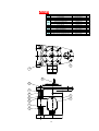
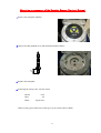
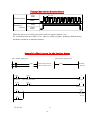
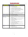
1
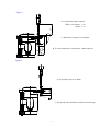
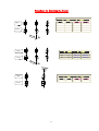
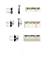
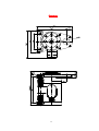
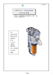
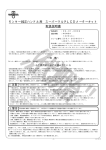
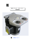
HIGH SPEED AUTO TIP DRESSER(CDK-R-400)
USER’S MANUAL
Please read this manual before using KYOKUTOH’S High Speed Tip Dresser (CDK-R-400)
KYOKUTOH CO.,LTD
G.E. Schmidt, Inc., founded in 1960, is a manufacturer and international distributor of
resistance welding machines and components throughout North America. We specialize in
pedestal welders, electrodes, tip dressers, quality assurance systems and nut/bolt loading systems.
11236 Williamson Rd.
Cincinnati, OH 45241
Tel: (513) 489-5130
Fax: (513) 489-5132
[email protected]
geschmidt.com
Cushway-Schmidt, Ltd. is a UK-based distributor, providing full-system solutions
for the resistance welding industry throughout Europe, from quality copper consumables
to welders and peripheral machines.
Unit 1 Hastingwood Business Centre
Hastingwood, Harlow CM17 9JH
Tel: +44 (0) 1992 713 749
Fax: +44 (0) 1279 436 318
[email protected]
cushway-schmidt.co.uk
ATTENTION TO SAFETY
※ Please be sure to read ATTENTION TO SAFETY before using CDK-R
This product is intended only for the dressing of specified electrodes. This product is not to be used in any
manner other than that which is specified within. We will not be held responsible for damage or injury
caused as a result of misuse of this product.
SYMBOLES
※ This following symbols “Caution” and “Notice”, are used indicate possible hazards and to prevent
their occurrence.
△
!
!
△
Caution
Be careful to follow directions as specified, as an error could lead to possible injury or
death.
Notice
Be careful to follow direction as specified, as an error could lead to malfunction and
serious damage.
The following symbols are explained below.
○
This symbol indicates operations that should not be done.
!
○
This symbol indicates operation that should be done.
※ After reading, please the manual to the place where you can check the manual.
Caution
Absolutely
never
disassemble
or
reconfigure this machine or its parts.
○ This could result in oper ation
malfunction, ignition, or injury.
Avoid as much contact with water as
possible.
○ This could result in oper ation
malfunction (short), electr ical shock or
ignition.
Be sure to switch off the power supply,
when removing or repairing wiring.
○ Will cause electr ical shock.
Remove the spatter, which covers the tip
dresser periodically.
○ Spatter build-up can cause oper ation
malfunction or ignition resulting in
injury.
Remove any oil that may accumulate on the
tip dresser.
○ Spatter could cause ignition and
possible Injury.
Be sure wire from power supply is of
correct capacity. (10A/1unit)
○ Incorrect wir ing could result in
oper ation malfunction or ignition
Do not allow power supply wiring to
become damaged.
○ Wiring damage could result in
oper ation malfunction and ignition.
Do not insert a finger or hand into gear
opening while in operation.
○ This will result in ser ious injury.
Do not insert metallic articles such as a pins
or needles in gear or terminal box opening.
○ This could result in oper ation
malfunction or electr ical shock.
Be sure that spatter does cover any wiring.
○ This will prevent the melting of wire
membr ane and a potential shock hazard.
Do not use acidic or chlorine detergents for
maintenance purposes.
○ Poisonous gas may be gener ated from
the detergents, causing a possible health
risk.
Do not use voltage other than that which is
specified.
○ Excess heat could cause oper ation
malfunction and ignition.
Use wiring of enough thickness. (2 sq mm
or more)
○ Incorrect wir ing could result in
oper ation malfunction or ignition
Notice
Firmly fix tip dresser to stand.
○ If the Tip Dresser is not fixed tightly
in oper ation, poor dressing and other
problems could occur.
Do not use any cutter or holder other than
that which is intended and specified.
○ Use of an unspecified cutter or holder,
could result in damage.
Do not install between a welding machine
and a transformer.
○ Strong magnetic forces and heat can
be dangerous and possibly cause
malfunctions or ignition.
Be sure that the motor is not locked up.
○ This could result in over heating and
possible ignition.
Do not install near the thermal generation
source of the welding machine.
○ This could cause trouble and
accidents.
Do not use rotation direction beside set.
○ This could cause trouble and
accidents.
INDEX
CDK-R Tip Dresser Capabilities
1
Criteria for Dressing Guns
2
Cautions for Positioning the Dresser 1
4
Cautions for Positioning the Dresser 2
6
Wiring to the Dresser
7
Cutter Capacity and Dressing Time
8
Timing Chart
9
Cutter Replacement
10
Procedure for Selecting the Cutter
11
Drawing
13
Parts List
14
How to Change the Cutter
15
Mounting arrangement
of the Rotation Sensor (Optional Extras)
17
Timing Chart for the Rotation Sensor
18
Example Ladder Program
for the Rotation Sensor
18
Cautions and Confirmation
before the Operation
19
Abnormality and How to Repair
20
Consumption Parts List
22
Periodic Maintenance
23
CDK-R Tip Dresser Capability
Model
CDK‐R
-400
CDK-R
-400H
Power
Freq
Current
AC380V
50 Hz
2.4 A
50 Hz
2.4 A
60 Hz
2.2 A
AC415V
50 Hz
2.4 A
AC440V
60 Hz
2.0 A
AC460V
60 Hz
2.0 A
AC480V
60 Hz
2.1 A
AC400V
Rpm
227
rpm
228
rpm
277
rpm
230
rpm
280
rpm
282
rpm
280
rpm
Torque
Output
Mass
Rated Time
Rated
Kg
34.6 N.m
34.3 N.m
28.3 N.m
34.1 N.m
28.0 N.m
1k
W
Rated
output
continuous
use time
5minute
17.8
kg
27.8 N.m
28.0 N.m
※ Dresser motor and terminal box have protection structure.
IEC STANDARD
IP54 APPROVED
〖Features〗
1. Dress upper and lower tips simultaneously, therefore, dressing time is reduced.
2. Our KTW cutter enables cap tips to be dressed with the pressure between 1078N (110kgf)
and 1960N (200kgf); furthermore, our cutter for high-pressure gun makes it possible to
use higher pressure between 1960N (200kgf) and 2450N (250kgf).
3. Floating mechanism greatly reduces stress on welding gun and dresser.
4. KTW cutter reduces dressing time.
1
Cr iter ia for Dressing Guns
(Applicable to both X-guns and C-guns; see figure 1 and 2)
1.
If A dimension is less than 30mm, this dresser is not suitable, because it may contact
gearbox.
Ref. Some special cutters require up to 35 mm.
2.
If B dimension is less than 50mm, this dresser is not suitable, because it may interfere
with gearbox.
3.
Cap tip with “C” angle up to 15 degrees can be dressed.
When using the eccentric tips or guns with angle, please contact us.
4.
When the length of shank of D dimension is long, contact us for solution.
5.
The base tip and insert electrode requires a particular cutter. (E dimension)
We will customize the cutter if you could provide us the gun and tip drawings.
6.
Recommended dressing force is between 1,078N and 1,470N. (Dress up to 110kgf to
150kgf)
When dressing pressure is less than 1,078N, there is possibility of dressing defective
because of dressing amount reduction.
High dressing pressure from 1470N to 2450N might make the dresser stop or damage
the cutter and holder, depending on the shape of cap tips. In this case, please reduce
the dressing pressure. If it is impossible to reduce the pressure, please contact us. We
would offer you some other special cutters.
It is necessary to reduce dressing pressure when it is more than 2,450N.
7.
Select a cutter well suited to the tip shape.
8.
For other specifications for the CDK-R, please contact our sales department.
2
Figure 1
D. Concentricity guide required,
If this is over 90mm-φ16
70mm-φ13
C. Maximum 15 degrees is acceptable.
B. To avoid interference with gearbox, 50mm required.
Figure 2
A. Tip opening needs over 30mm.
E. The special cutter should be used for the shorter tips.
3
Cautions for Positioning the Dresser 1
1.
The tip should be set parallel to floating mechanism. (See figure 3)
2.
For X-guns, set the dressing location to the pressurization location. (See figure 4)
3.
For C-guns, set the dressing location even level with pressurization location, otherwise it might
cause poor dressing or damage gears and bearings.
4.
Although the floating mechanism is installed in dresser, we also recommend that you locate the
dressing position as closely as possible.
5.
Dressing horizontally C-Guns vertically set with equalizing mechanism is difficult to keep weight
balance of springs, and pressurization point could easily change. So in this case, please make sure
of pressurization point very well when you teach robots. (See figure 4 and 5)
Figure 3
4
Figure 4
図
(5)
Figure
5
5
Cautions for Positioning the Dresser 2
*Perpendicular to Floor
*Horizontal to Floor
Upper
①
Lower
②
④
Perpendicular to Floor (CDK-R-T)
Horizontally (CDK-R-Y)
①Spring
CDK-R-003
③Spring
CDK-R-003
②Spring
CDK-R-002
Because spring takes dresser weight in the
(Upper) ② use the spring Full length which
is 20mm longer than lower.
When it is installed upside-down, the
spring of the ①.② must be replaced and
used.
④Spring
CDK-R-003
③
Use same spring for ③ and ④
※ When you place order, please let us know installation method (Perpendicular to Floor or
Horizontal to Floor). If not, we would supply you standard type, Vertical mounting.
6
Wir ing to the Dresser
Terminal Box
Circuit Diagram of The Motor
LID
Dresser CDK
THERMOSTAT
FUSE OUTPUT
THERMOSATAT FUSE
FRAME GROUND
FUSE
OUTPUT
EARTH
SEAL CONNECTOR
Use over 2sq power wire. (AWG Gauge NO14 equivalent)
Strip coating, and wire directly.
Recommended stripping length is 10 mm.
If it is difficult to wire, use pin terminal. (NICHIFU TC-2 equivalent)
Do not wire when the switch is on. (Be sure to turn off the switch.)
The operator must have the certification approved as an electrical worker.
Please take the cable’s change (shrinkages or slack) into consideration when wiring because the
floating mechanism is installed on K-type dresser.
Because the floating mechanism is installed, make sure the terminal bolt is tightened. (We
recommend that you make a circle with cable beside the dresser in order to absorb the vibration.)
Please wire power cord and thermostat fuse output cord separately for your security.
When using thermostat fuse, make the side hole on the terminal box of dresser.
When not using the installed thermostat fuse, please set the overloading protector beside the
dresser.
7
Cutter Capacity and Dressing Time
.
加圧力と研磨量の関係
Graph of Dressing
pressure and Dressing Amount
0.35
Tip material of Electrode CuCr
研磨量(mm)
0.3
Tip of Electrode
0.25
0.2
φ6-8R(φ16)
Type of Cutter
KTW-12T
Number of Revolution
272 rpm(60Hz)
0.15
0.1
0.05
0
Amount (mm)
50
100
150
Dressing 加圧力(kgf)
pressure (kgf)
200
250
Estimated Dressing Time
Dressing time: 1 sec
Please adjust dressing time and pressure according to above graph.
○ Example 1: to dress 0.1mm
Dressing time: 1 sec
Dressing pressure: 110kgf
○ Example 2: to dress 0.1mm
Dressing time: 0.7 sec
Dressing pressure: 150 kef
Above examples are rough indications for the default. If you find cap tips are
dressed not enough or too much while using, please adjust the setting to your cap
tips.
Average dressing cycle of KTW cutters after 200 welds is 1 to 2 seconds.
We have various types of cutters with different shapes and different metallic finishing for
optimum dressing. So even if you changed the length of dressing time or the amount of
dressing pressure and still couldn't get better result, please contact us.
8
Timing Char t
KTW type Cutter (Only clockwise rotation)
1-3 sec.
ON
Gun Pressure
OFF
Dresser
Rotation
ON
OFF
① Start motor to clockwise before Gun press.
② Set the dressing time according to your tip condition. Approximately 1-3 sec.
③ Confirm rotate direction (clockwise).
④ To finish dressing, release the gun pressure while dresser is revolving.
Before operating, make sure that the forms of cutter and tip are fitting.
When dressing is finished and small scrapes are left on the cap tips, both upper and lower
tips should be touched with the cutter of revolving dresser before returning to original
position.
9
Cutter Replacement
KTWカッター耐久データ
Duration
data of KTW Cutter (25 – 30,000)
Dur ation data of (25回~30,000回)
KTW Cutter (25-30,000)
0.5
Lower
下側チップ
0.3
0.2
0.1
Amount (mm)
30,000
28,000
26,000
24,000
20,000
18,000
16,000
14,000
12,000
10,000
8,000
6,000
4,000
2,000
0.0
25
研磨量 (mm)
上側チップ
Upper
0.4
Number of
Dressing(1秒)
1 sec
研磨回数
As seen on above, even after 30,000 dressing cycles, consistency of our cutter virtually unchanged,
however, cutter life span differs from the condition of cap tip.
As for average example, we set exchange timing when the dressing amount is half compare to the very
beginning amount.
(Example)
Tip material of Electrode
Cr-Cu (new one)
Type of Electrode
1623-A (RR-6-8R)
Type of Cutter
KTW-12T (RR-6-8R)
Number of Revolution
272 rpm
Gun Force
1,960N(200Kgf)
The Dressing Conditions
Dresser Revolution→Gun Pressure (1 sec)→Gun release→Dresser stop
The measuring of one time (one second)
= The tip length before dressing- The tip length after
dressing
Above example resulted in the fact that aver age dressing quantity is 0.2mm for 1 second.
It means when the dressing quantity gets less than 0.1mm is the time to change the cutter.
We used new cap tips for the experiment, however, how fast cap tips get short actually depends on the
situation such as the kind and thickness of steel sheet to weld and the amount of electric current. It
sometimes happens that the point of cap tip gets crushed and alloyed, and extraordinary hard.
Therefore the life length of cutters is not always same.
Changing the dressing condition might be effective to make the cutter life longer.
The most important thing is to choose proper cutter and proper dressing time for each dresser.
☆For further information , please request the cutter instruction manual.
10
Procedure for Selecting the Cutter
D
Type :
Upper
Upper
Lower
Lower
Cutter
φ4 X R8
φ4 X R8
KTW-10
KTWH-10
φ5 X R8
φ5 X R8
KTW-11T
KTWH-11
φ6 X R8
φ6 X R8
KTW-12T
KTWH-12
φ8 X R8
φ8 X R8
KTW-13T
KTWH-13
Upper
R
Lower
R
Type
Lower
Cutter
Holder
R6.5
6.5
KTW-15T
KTWH-15
R8
R8
KTW-16T
KTWH-16
D
11
Type :
Holder
Upper
Upper
Lower
D Type
Type :
R
Type
Upper
Lower
Cutter
Holder
φ6 X R8
R40
KTW-14T
KTWH-14
D
Upper
Type :
F
Type
Upper
Lower
Cuter
Holder
φ6 X R8
φ16
KTW-23
KTWH-23
φ6 X R8
φ13
KTW-24
KTWH-24
Lower
C
Upper
Upper
Lower
12
Type
Cutter
Holder
φ4 X 30°
φ4 X 30°
KTW-01
KTWH-01
φ5 X 30°
φ5 X 30°
KTW-02
KTWH-02
φ6 X 30°
φ6 X 30°
KTW-03
KTWH-03
φ8 X 30°
φ8 X 30°
KTW-04
KTWH-04
Upper
Lower
C
Lower
C
Upper
Type :
Type :
C
Type
Lower
Cutter
Holder
φ4 X 45°
φ4 X 45°
KTW-05
KTWH-05
φ5 X 45°
φ5 X 45°
KTW-06T
KTWH-06
φ6 X 45°
φ6 X 45°
KTW-07T
KTWH-07
φ8 X 45°
φ8 X 45°
KTW-08T
KTWH-08
Dr awing
13
Par ts List
NO.
Par ts Name
Type or Size
1
2
3
4
Tip Dresser
Terminal Box
Output Bearing
Shaft Plate
Spring for Vertical Type
Spring for Horizontal Type
Upper Spring
Shaft
Slide Bearing
C-Ring for Bearing
Flat Washer
Cap Screw
Rotation Sensor (Optional Extras)
CDK-R-400
Include Motor
6809DD
CDK-R-001
CDK-R-002
CDK-R-003
CDK-R-003
CDK-R-004
LM20LUU
For 32 Axis
For M20
M8X25
E2E-X1(M5)
5
6
7
8
9
10
11
12
3
4
12
11
6
7
1
2
10
8
9
5
14
1
1
2
2
2
2
2
2
2
4
4
4
1
How to Change the Cutter
1. Remove M3 screws from the cutter holder.
2. Remove the cutter holder from the dresser.
3. To remove the cutter from the cutter holder, loosen the M3 torque screw.
(With a torque wrench T-10)
15
4. Replace a new cutter
Confirm cutter is replaced in the proper direction.
Please install the angle narrows on the side where touches the holder. (Inscription faced up)
(Recommended torque for M3 screw is to 10-12kgf.cm).
Cutter Holder
Cutter
Inscription side
OK
Cutter Holder
Cutter
NG
5. To install the cutter holder to the dresser, please do the reverse order from 1 to 2.
16
Mounting ar r angement of the Rotation Sensor (Optional Extr as)
1. Remove the nameplate (M4X4).
2. Remove the M5 panhead screw and install the Rotation Sensor.
3. Replace the nameplate.
4. Following the wiring color, wire the sensor.
Brown
Blue
Black
+24V
0V
Signal wire
Before wiring, please make sure of the type of your sensor (NPN or PNP).
17
Timing Char t for the Rotation Sensor
0.1 sec
ON
Rotation Sensor
OFF
ON
Rotation of
Dresser
OFF
While the dresser is revolving, the sensor sends out signals 1pulse/0.1 sec..
We recommend that more than 0.5 sec. input or cutting of signal, including initiation delay,
should be considered as abnormal rotation.
Example Ladder Progr am for the Rotation Sensor
[PLC (Robot) Input side]
R1000
[PLC (Robot) Output side]
(1000)
Startup Signal of Dresser
(1000)
Signal of Rotation Sensor
R1001
(1500)
Abnormal
Rotation
#1
T1
Dresser Start
R1000
Dresser Start
Signal of Rotation Sensor
Signal Input
R1001
#1
T2
Signal of Rotation Sensor
Signal disconnect
T1
R1500
Signal Input
Abnormal
Rotation
T2
Signal disconnect
#5=0.5 sec.
T2
18
Cautions and Confir mation before the Oper ation
1. Confirm the specification again. (Voltage, option, etc)
2. Make sure of the conformity between the forms of cutter and cap tips.
3. Install the dresser in the place where the operator can not touch it directly during the operation.
4. Make sure dresser and stand bolts are tightened firmly. Also, confirm stand is fixed securely to the
floor.
5. When connecting wires to the dresser, operation procedures must be followed with the electric
construction standard and also make sure that it is protected from cooling water and spatter.
6. Be certain dresser is grounded.
7. Make sure dresser is installed in a location with no spatter and cooling water directly.
8. Confirm the forms of the cutter and cap tips once again before robot teaching,
Confirm that cutter and holder are securely fastened.
9. Confirm the rotation direction of the KTW cutter is clockwise.
10. Make sure there is neither interference to the dresser except for the cap tips, nor any allophone
when robot teaching.
11. When the gun is pressurized, make sure that the electric current is not applied and pressure is
within the setting range.
12. Confirm the quality of the dressed tip. Be sure that the shank is stable and not shaking during
dressing.
◆The causes of the failure in dressing.
The gun is not released while the dresser is revolving. (Scrapes are left on the cap tips)
The pressure is too high or too low.
The forms of the cap tip and the cutter are not fitting.
The dressing time is too short.
The teaching point differs from the dressing one.
The shape of used cap tips differs from new ones too much.
◇If the cap tips can’t get dressed properly with any other reason, please contact us.
19
Abnor mality and How to Repair
Abnor mal Condition
Dresser does not rotate.
The motor is running but
the cutter does not rotate.
The diameter of the
dressed cap tip is different
from the setting.
Abnormal
dressing.
sound
during
Cause and Counter measure
* The power switch is OFF.
→ Check the power source.
* Wire is cut-off or poor contact.
→ Check the terminal box and control panel.
* The thermostat fuse of motor side is working.
→ Check the motor and reset it after cooling down.
* The gun pressure is higher than specified by our company.
→ Set gun pressure under 1960N(200kgf).
* Motor is broken.
→ Need repair to replace the motor.
* The shapes of the cutter and the cap tip are not fitting, and
cling each other.
→ Check the cutter shape and replace it if necessary.
* Gear in the gear box is broken.
→ Need repair to replace the gear.
* Dressing time is too short.
→ Set the dressing time to the tip that has been
crushed most.
* The cutting capability of the cutter has deteriorated or the
cutter has been damaged.
→ Replace the cutter and check the gun pressure.
* Dressing point is not proper.
→ Re-do teaching.
* The cutter is not suitable for the cap tip.
→ Check the cutter shape and replace it if necessary.
* Gear in the gear box is broken.
→ Need repair to replace the gear.
* The screw which fastens the cutter to the holder is loosen.
→ Tighten the screw.
* Dressing point is not proper.
→ Re-do teaching.
* The cutter has been damaged.
→ Replace the cutter and check the gun pressure.
20
Abnor mal Condition
Cause and Countermeasure
Dresser leaves burr on the * The control method is not proper.
cap tip.
→ Release the gun while dresser is revolving, and then stop
the dresser.
* The shapes of the cutter and the cap tips are not fitting.
→ Check the cutter shape and replace it, if necessary.
* The cutter has been damaged.
→ Replace the cutter and check the gun pressure.
* The screw which fastens the cutter to the holder is loosen.
→ Tighten the screw.
The tip diameter is not at * The cap tip has got too short.
the center or the designated
→ Replace the cap tip to new one.
location.
* Dressing position is not proper.
→ Re-do teaching.
The point of the cap tip is * The bolts that fasten the motor and the gear box are loosen.
an oval, not a circle.
→ Tighten the bolts.
* The bolts that fasten the dresser to the stand are loosen.
→ Tighten the bolts
Dressing does not complete * The cutting capability of the cutter has deteriorated or the
in the set time
cutter has been damaged.
→ Replace the cutter and check the gun pressure.
* Dressing time is too short.
→ Set the dressing time to the cap tip that has been
crushed most.
* The cap tip is soften after welding, the point of the cap tip
gets widened.
→ Increase the dressing pressure gradually according to
the time of dressing a cap tip when it is with gun voltage
valve.
<Remarks>
Please be sure the switch is off when you are checking or replacing parts or the
cutter.
When the dresser is out of order, please contact us immediately. Do not take the
dresser apart. It would not be able to repair if you disassemble it.
21
Consumption Par ts List
Outsourced Product
* Bearing for tip dresser
Type:
6809DD
(6809DD equivalent)
Replacement Qty: 2pcs.
Replacement cycle: When total dressing time gets
500 hours or 6 months
Parts List:
P14 Figure No③
* Output gear with bearing for KTW cutter.
Type:
1MO4CC006-00
(TDR-E-P-006-2 equivalent)
Replacement Qty: 1pc.
Bearing replacement cycle: When total dressing time gets
500 hours or 6 months
Gear replacement cycle: When total dressing time gets
2000 hours or 2 years
* Cutter
Type:
Reference to P11・P12
Replacement Qty: 1 pc.
Replacement cycle: Total dressing time, 20000sec.
* Cutter holder
Type:
Reference to P11・P12
Replacement Qty: 1 pc.
Replacement cycle: Total dressing time, 100000sec.
The bearing replacement cycle is 6 months: Without operation for a long time, the
grease might resolve inside the bearing. In this case please lubricate by a grease spray
and the like before operation.
22
Per iodic Maintenance
Maintenance place
To the gearbox, grease supply
How to maintenance
Remove the nameplate.
Remove 1/8 screw from the upper side of the gearbox.
Install grease nipple.
Supply the greased with grease gun.
Grease is MPG♯2 equivalent.
One time per 6 months, 20g supply.
Prevent from dust in case of supply.
23