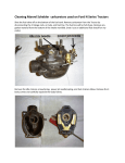
1
Overhauling the Ford 9N Engine: Part 1 –
Engine Removal, Disassembly, and Evaluation
by John Korschot - www.johnsoldiron.com (December 2010)
This "how to" is not intended to replace a good technical manual like the I&T FO4, it’s intended to be a companion with
many more photos, tips, a general dis-assembly sequence, and parts evaluation guide.
The goal of writing this was to provide general advice on what to re-use and what to replace. Deciding what to use over
can at times be somewhat arbitrary so whenever possible follow technical specifications first. If you sleep better at night
replacing everything do that it as it’s your tractor. I personally only replace items when they do not meet the standard for a
usable part. For example, on the last 9n I rebuilt I replaced 1 valve spring as it did not measure the minimum compression
reading at a defined height. The remaining 7 passed so I re-used them.
The more you know about the condition of the motor before tearing it apart the more likely you are to spot defective/worn
parts and be successful in your overhaul. Whenever possible run the tractor as much as you can and evaluate it prior to
teardown.
Did the engine use too much oil? Did the motor miss? Did the motor knock? How was the oil pressure? Did it have a lack
of power? When possible, before tearing the motor apart complete a compression test.
A common question asked is "can I do an in-frame rebuild”? The short answer is not really, or at best not completely. The
problem is that the oil pan is an integral frame component on an N series tractor. Many tractors manufactured at the same
time had an external frame that the motor set in. This is something Henry Ford designed out. In order to access the
bottom of the motor the pan has to come off which is what the front axle bolts to so the entire front axle has to come off
anyway. Valve jobs, re-ringing pistons, and re-sleeving are candidates for being done in frame. New crank bearings are
possible provided the crankshaft does not have to be removed.
With the block still attached to the transmission there is no way to renew the upper rear oil seal. The split rope seal is a
poor design by today’s standard and should be replaced when removing the pan. There are stories of users jamming
additional rope seal material (string type) from Ferguson TO series motors into the upper seal area but if you are this far in
why not pull the motor and place it on a stand?
Another common question is “I have a 49 8n, what overhaul kit do I need”? The short answer is there is no way to know
without a full teardown and evaluation of the existing parts.
Perform a compression test for each cylinder with all the plugs removed and throttle wide open. Record your results. It’s
not critical that your gage be super accurate just use the same gauge on all 4 cylinders and record the results. Differences
in readings between cylinders are as an important reading as is overall compression. While an overhaul may be imminent
it’s helpful to know if you have a problem before you start in case you need to identify the cause later. If the compression
reads low (below 90 psi) add a tablespoon of oil to each cylinder and re-test. If the readings improve it’s indicative of worn
rings, if the readings remain the same its indicative of valve problems.
One tip I can offer is to photograph everything every step of the way. While the disassembly may be fresh now it may be a
while before the motor is re-assembled. Having pictures to fall back on is critical. Also remove, clean, and bag all small
parts and fasteners per assembly item and label the bags. There are over a hundred parts to a motor and its best to have
them organized. Another tip is to mark all wires from where they were removed.
There are numerous sources out there that describe pulling an N motor which include:
Ford Service Manual for Owners and Mechanics
Ford Service Training Job plan available at www.ntractorclub.com
I&T Shop Service Manual Ford 2N-8N-9N (FO-4)
Ford 8N Motor Overhaul DVD (available at www.ytmag.com)
www.ntractorclub.com
Removing the Motor
Remove the radiator cap and open the block drain and drain the radiator into an approved container and dispose of used
antifreeze properly.
Drain the engine oil and filter into an approved container and dispose of used oil properly.
Remove the oil filter canister and set aside.
Remove the fuel line at the carburetor and drain the fuel tank into an approved container.
Remove the fuel line.
While the tank is draining remove the steering wheel (9ns and 2ns)
Loosen any through the hood air cleaner parts usually at the top of the air cleaner body (2N) or side of hood (8N).
Disconnect the battery cables, disconnect headlights if equipped.
Remove the front dog leg to axle support bolts 2 on most Ns, 8 on early 9ns
Remove the 4 hood to dash bolts
With a helper remove the hood by lifting up first from the grill causing the hood to clear the radiator neck, then at the dash
end raising the entire hood free of the tractor.
Remove the radiator and hoses. The Radiator has 2 7/16 carriage bolts with captive heads in the radiator. Remove the
nuts from under the axle support
Remove battery (all) and tool box (8n)
Remove the air cleaner tube
Disconnect the muffler from the exhaust manifold
Disconnect all wiring on the motor, remove the 2 nuts holding the wiring tube on, and fold the wiring tube (front mount
distributor) and wiring back onto the tractor.
Remove the spark plugs and set aside.
Remove the fan from the water pump (easier while the fan belt is on)
Remove the generator, fan belt, and water pump.
Remove the starter and wiring from the starter and fold back onto tractor.
Remove oil line from the distribution block to the dash
Remove all throttle linkage from the dash area to the governor and to the carburetor.
Remove the choke rod and carburetor.
Remove the exhaust manifold.
Remove the governor.
Remove the 2 valve covers.
Remove the battery support
www.ntractorclub.com
Place the transmission in gear and set the parking brakes. If the brakes don’t work block the rear wheels from rolling
either direction
I like to remove the head prior to pulling the motor. The studs or bolt holes provide a way to attach a chain for hoisting the
motor.
Using a 2” stiff putty knife, drive it carefully in at the gasket between the head and block. Be very careful and pry only a
little at a time. Keep working around the head taking very small bites close to one another. Once around increase slightly
how far in you drive it and how much you pry. Be careful not to force too much, if the head has been on for years this may
take a while. Getting rough here may cause gouges to the head and/or block surface so take it easy. Remove the head.
Remove the bolts/nuts from the studs and any brackets. With the head removed inspect the top of the motor for unusual
damage.
Valves will likely be covered in carbon as the top of the pistons as well. Shiny piston tops indicate a leaking head gasket.
The water has been entering the cylinder and has cleaned the top of the piston.
At this point it’s time to attach a lifting device to the motor. The motor weighs around 400lbs. Plan on using something with
2x the load capacity to lift safely. Observe any markings on engine puller as generally speaking the further you lift from the
lift cylinder the lower the capacity of the hoist.
I personally use a 5/16 chain attached to 2 studs at opposite corners of the block. This should only be done if the block is
in good shape and there are no cracks near the studs used. Inspect closely the rear stud right side (next to exhaust
manifold) as this location is sometimes cracked. The chain should have slack and be able to be raised with at least a 45
degree angle on steeper on the chains. Run bolts in as far as the holes are tapped and use several flat washers under the
heads. Caution should be exercised when doing this as sudden shock loads could cause the corner of the block to break
out so take it easy doing it this way,
Other options include nylon slings. If in doubt contact someone with experience. Be careful of slinging type arrangements
so that the sling can't slide on the block while moving the motor.
Raise the motor just enough to lighten the load on the front axle and take all slack out of the chain.
www.ntractorclub.com
Remove the drag links from the steering arms. Loosen (don’t remove) the nuts on the bottom and with one hand pull up
on the drag link as the other hand hammers the steering arms with a standard ball-peen hammer. The drag link should
pop loose, and then remove the nut. Rotate the drag link backwards and rest on the rear axle.
Remove the radius rod caps located the foot pegs/boards. Pop the ball ends out of the sockets. At this time it will be
apparent how much play is in the front axle support busing. With a tight bushing the arms will come out and drop just a
little. A sloppy front busing will allow the arms to drop quite a ways.
Remove the 6 bolts connecting the front axle support to the motor oil pan. With a helper roll the front axle out of the way
Raise the motor a little and prepare a suitable support under the transmission. When prepared lower the motor carefully
landing the transmission on suitable blocking. Do not use cement/cinder blocks. The goal is to have the tractor
transmission/rear end level when setting on blocks.
Keep tension on the chains/straps supporting the motor. Remove the bolts connecting the motor to the transmission
Using a stiff putty knife carefully drive it in at the joint between the transmission and block. Be very careful and pry only a
little at a time. Keep working around the motor taking very small bites. Once around increase slightly how far in you drive it
and how much you pry. Be careful not to force too much, if the motor has been attached for years this may take a while.
Be prepared for the motor to break loose and swing away from the transmission. There is nothing holding it in at this point
except paint, old grease, 2 dowel pins, and rust. Once the motor separates from the transmission roll one away from the
other.
www.ntractorclub.com
Disassembling the Motor
Lower the engine block close to the floor and lay several layers of cardboard down in case the flywheel gets away from
you. Remove the clutch (6 bolts) and flywheel (4 bolts) from the back of the block. The flywheel is quite heavy and there
isn’t enough room to get your hands around the flywheel while still attached to the crankshaft. You may have to use a
combination of tapping on the flywheel with a heavy soft mallet and prying on it at times to get it to separate from the
crankshaft. It is located on 2 dowel pins and will have to move back some before coming off.
Raise the motor and securely fasten it to a motor stand using at least 4 bolts threaded all the way into the block. I use the
small stand from Harbor Freight but any one will do. Here an N owner has made some custom spacers for his motor
stand. All 4 bolts need to be tightened securely and the mounts should all contact the block at the same time.
Remove the valves. Rotate the crankshaft to a place where the valve spring of the valve you are working on is relaxed.
The crankshaft drive nut is 1 5/16 and can be used to rotate the crankshaft. The nut is right hand fine thread. The exhaust
valves can be very difficult to remove. The valves are removed as an assembly.
Use a modified large screwdriver as a valve removal tool. Valve assemblies that are difficult to remove may be soaked
with penetrating oils. Direct the penetrating oil to the edges of the valve guides in the block. In worst case scenarios I’ve
had to cut valve stems off (mushroom style) and drive the rest of the valve up out of the guide. Then the guide can be
driven down with a brass drift enabling the removal of the keeper then driven up and out.
www.ntractorclub.com
The tool is placed in through the intake/exhaust ports and the hook end is placed on the top of the valve guide and the
handle is raised against the block which should force the valve guide down compressing the valve spring.
The valve guide is depressed approx. 1/8” which allows for removal of the valve guide keepers. Once removed the entire
valve assembly can then be pulled out the top of the block. Note: It is not possible to remove the keepers without driving
the guides down first.
www.ntractorclub.com
Here an N owner has removed the valves as assemblies. Mark the valves for their locations and set aside.
With the valves out remove the lifters. They should lift right out.
Roll the motor over on the stand and remove the pan. Remove the numerous 5/16 bolts from the pan. Note: there are 2 at
the front of the pan under the crankshaft pulley often hidden under old dried oil.
Using a stiff putty knife carefully drive it in at the joint between the pan and block. Be very careful and pry only a little at a
time. Keep working around the motor taking very small bites. Once around increase slightly how far in you drive it and
how much you pry. Be careful not to force too much, if the pan has hasn’t been off in years this may take a while. It’s
possible to break the pan by forcing it too much. Also it’s important that the pan come off somewhat level to the block.
www.ntractorclub.com
Numerous pans’ rear seal retainers have a corner broke off which is believed to be caused by improper pan removal. Also
important is the oil pickup tube visible through the pan drain plug. Take care not to damage the pickup tube removing the
pan. If the pan does not come off make sure you have all the bolts out. Lift the pan off and set aside.
From the front of the motor remove the 1 5/16 crankshaft nut. This is a right hand fine thread fastener. It’s not uncommon
to need an impact gun and socket to remove the nut. With the nut off pull the crankshaft pulley off. It’s held in place by the
nut, keyed to the crank shaft, and usually is easily removed.
Remove the bolts holding the timing cover and governor mounts. Use the normal method to split the gasket and remove
the parts. There are 2 dowel pins aligning the timing cover. Remove the oil slinger from the crankshaft and set aside. Your
motor may also have a special thrust spacer washer on the end of the camshaft. Set that aside.
www.ntractorclub.com
At this point the crankshaft, cam, and oil pump gears are exposed and it’s time to check them. For lack of a better term,
each tooth should have the contour shown, widest at the bottom, then a point midway up the tooth where it begins to
narrow quicker. A worn tooth may be missing the wide spot where it’s nearly a straight line from base to the top of the
tooth and is worn out.
Check the gear lash between the crankshaft and cam gears. Here I've cut a feeler gauge to fit between the teeth. If the
gap exceeds the tolerance a new cam gear is probably in order. The maximum gear backlash (space between the gear
teeth) is .006.
After inspecting the gears remove the camshaft by pulling it straight out the front of the block and set aside. You will have
to rotate the shaft as it dis-engages from the crankshaft gear.
www.ntractorclub.com
Examine the tops of the cylinders where the pistons are not at the top of their travel. When the piston travels up and down
the cylinder wall wears to the point of the top of travel of the top ring (red arrow). The non-worn area at the top of the
cylinder is referred to as ring-ridge. The ring-ridge area will be the original bore of the sleeve and slightly smaller ID than
the now worn sleeve. If your motor has any detectable ring-ridge you will have to use a ring-ridge cutter to remove it or
plan on removing the pistons from the bottom of the block. Trying to remove the pistons from the top of the block with ringridge present can break rings, gouge pistons, or possibly even break sections out of the ring lands (area of piston
between the rings). I remove my pistons from the bottom of the block.
Roll the motor over on the stand and remove the crankshaft. Your motor may have safety wire fastened through the nuts,
cut it out with diagonal cutters.
www.ntractorclub.com
Remove the nuts on the connecting rod caps. Be careful to note the orientation of the caps (front/back- left/right side and
position 1-4). Set the caps aside. Any bearing shells that fall out should be captured and saved for evaluation. Pistons
may be pushed up to the top of travel to aid in crankshaft removal.
Remove the main bearing caps. The center and rear have an arrow pointing toward the front. The front cap is also the oil
pump. Remove and set aside.
Lift the crankshaft out of the block and set on a sturdy work surface.
Return the connecting rod caps to the correct rods in the correct orientation to keep them from becoming lost or
mismatched. Most pistons I’ve seen have had some kind of marking on them indicating forward. The mark may be a small
arrow or some have the identifying marks like std stamped at the front of top of the pistons. If no identifying marks are
found take a small center punch and small hammer and stamp a small punch towards the front of the piston. You may
want to punch 1 dot for #1, 2 dots for #2 etc. Also look at the connecting rods as they should have the numbers 1-4. If the
pistons and rods are going back into cylinders that are not being bored or replaced it is standard practice to install the
pistons in the same cylinders from where they came.
Pull the pistons out from the bottom of the block and set aside.
At this point it’s nearly time to start evaluating parts. I prefer to degrease my parts prior to inspection. Using your favorite
degreasing method, clean all the parts. Be aware of flammable solvents and use appropriate safety gear with the best
ventilation possible. I determine if my parts need to go to the machine shop prior to taking them there so as to not waste
money say on hot-tanking a block that is cracked.
www.ntractorclub.com
Evaluating engine parts
This section is intended to provide the end user with advice on how to determine what to use, what to replace, and when
to head to the machine shop. Ultimately it’s your tractor, do what you are comfortable with. If you would rather haul it into
the machine shop and have them evaluate everything so be it. Some people are strict followers of specs and decisions
are very black and white. Some people like me use an approach of what do I expect out of the tractor when completed,
and I may be willing to tolerate some loose specs depending on what the final use is. Is it going to run 15 hours a year
moving on and off a trailer going to shows? Or is it going to be bush hogging 20 hours a week in the hot summer sun?
Ultimately it’s your call and if in doubt contact your local machine shop or post a question on one of the tractor boards.
Evaluating the Engine Block
Without a block you have no motor so let’s start there. I like to start with the most likely problems and work from there.
There’s no point measuring your block cam journal ids if it’s cracked.
During the 1940s antifreeze consisted of alcohol which over the year evaporated out of the cooling system. Consequently,
there are a lot of N’s running around with cracked blocks. While a cracked block isn’t necessarily a death sentence for a
running tractor I would not invest in rebuilding a motor with a cracked block unless it was a very special block like a 1939.
Cracks Emanating from the Block Drain Hole
This is the most common crack. This particular one was small enough that I didn’t see it when purchasing the tractor.
While not leaking I would not rebuild this block. This is in the very early stage and was not detectable as it was covered in
old paint and grease.
www.ntractorclub.com
The reason I would pass on rebuilding the block shown above is that it can quickly become this. Unless there is a special
reason for saving this block it would be best to locate a replacement.
Cracks in the Web between the Valve Cover Openings
This crack usually seen on the 9n blocks and is not a problem. Casting changes in later blocks solved this problem
www.ntractorclub.com
Other Cracks
Cracks can be found anywhere particularly when adjacent to water filled areas. This crack was reason to scrap this block.
While still a running motor this was a reason not to rebuild this block when the time came. Note the thin walled sleeves.
Cracks Near the Rear of the Block
Again, cracks can be anywhere, particularly when next to areas with water. Here a crack is found on the back of the
motor. This is a 1939 block and the owner rebuilt because of the year. For most blocks this would be the end of the line.
www.ntractorclub.com
Head Sealing Surface
Many people ask if their block should be decked. The answer is it depends. These blocks were cast and machined
originally some 50 +/- years ago. The deck surface is likely damaged by prying tools removing the head. Decking or resurfacing involves placing the block in a mill and milling off just enough material to remove the nicks, dings, rust, gouges,
etc. I’ve had 2 done and both required less than .010 material removal. While “decking” creates a better sealing surface
for the head gasket it can complicate engine building by reducing the clearance for the pistons with the head installed.
Decking should only be done if needed. Soft head gaskets are usually better at sealing with less than ideal head surfaces
but if you have to decide if you should run a soft gasket you may be due for a resurface.
This block has not been “decked” recently and is in great shape. There are no noticeable dings, nicks, gouges, or chips.
This block has some heavy nicks that are not in a gasket sealing area which is still ok. If the nicks are numerous and in
the gasket sealing area this one would be a candidate for “decking”. Note there is also some rust between 2 water ports
and if cleaned up would likely be lightly pitted. This block is borderline for needing to be “decked” or re-surfaced. Examine
closely the Fire ring imprint left by the head gasket around each cylinder. Imperfections in the surface here are trouble
when it comes to sealing a head gasket.
www.ntractorclub.com
This block is just back from the machine shop and has been decked. Note there is still some pitting between cylinders 2
and 3. The machinist stopped here as a compromise between removing all defects and taking too much material off the
block.
Intake/Exhaust Valve Seats
There are 2 questions. Do I need to have the seats ground and/or do they need to be replaced? The spec states that the
seat is to be no more than .125 wide. Most Ns have replaceable hardened valve seats.
These valve seats are from a tractor that was run until torn down. They measured right at spec. Notice they are shiny all
the way around and have no pitting although they have not been cleaned of all carbon deposits in this picture.
Do these seats need to be ground? In this case this is border line. These were not ground but were lapped with new
valves. One could argue that installing new valves in old seats is not a best practice but with no other reason to take this
block to the machine shop they were not ground. This tractor runs like a champ with 70 hours on the rebuild. If the block
had gone in for other reasons I would have had the seats evaluated further by the machinist.
Do these seats need to be replaced? No. Notice the black arrows. The arrows are showing that there is still seat material
to work with should they need to be ground. The exhaust seat (smaller) has less material left and has likely been ground
before.
www.ntractorclub.com
These valve seats are from a tractor that sat for years. They too measured at spec. The tractor had poor compression that
was not affected by adding oil to the cylinders. Notice they are pitted (exhaust) and actually have some ridges in the
sealing surface.
Do these seats need to be ground? Yes
Do these seats need to be replaced? Maybe, notice the black arrows. There is still plenty of seat material to work with on
the intake seat. The exhaust seat (smaller) has little material left and if ground will likely be the last time before needing to
be replaced- when I took this block in to the machine shop I planned on new exhaust seats but the shop was able to grind
them.
Block Cam Journals
The N block does not use cam bearings. The camshaft rotates in 3 wide journals in the block. The journals need to be
checked for wear. The bored spec is stated as 1.797. The minimum spec for the camshaft itself is stated as 1.795 which
would provide .002 clearance. The stated spec goes on to say that there should be no more than .004 clearance between
the cam and journal which means to me that the journal may be as large as 1.799. Clearances larger than .004 would
surely impact oil pressure. Measure each of the 3 journals in 2 places in the front and back of each journal (4 total per
journal), 180 degrees apart.
www.ntractorclub.com
Here we are measuring the front cam journal with a telescoping gauge. There are 2 spring loaded plungers that come out
and then are locked in place by the user. The tool is then removed and checked with a micrometer for the reading. The
feel of the instrument in the hole is something you have to work at to get consistent readings. It should have a slight drag
and be square to the largest part bore.
Checking the Center Cam Journal
www.ntractorclub.com
Checking Cylinder Bore
Evaluation of the cylinder bore will indicate if the sleeve can be honed or if it should be replaced. This is a fairly strait
forward decision. If the cylinder inside diameter is within spec and is not scored it can be honed and reused. If it is outside
of spec it must be bored larger or replaced.
Can this sleeve be re-used? Not likely. If the cylinder is still within spec you could hone in an attempt to remove the
scoring. If you were able to remove all the scoring and it remained within spec it would be ok.
If you have ring ridge at the top of the cylinder you are looking at replacing or boring the sleeve.
Cylinder bore spec is 3.1875-3.1885 Out of round wear limit is .003 and taper is .006. The sleeve should be measured 2
places at the top and 2 places at the bottom of the bore, 180 degrees apart. It is standard practice to install new rings
when cylinders are honed.
Identifying Sleeves
Sleeves come in 2 sizes. .040 Wall thickness early models and .090 in later Ns. Many old N blocks have since been rebored to accept the .090 sleeve. There is only one sure way to know what you have, drop the pan and look. Be advised
there are some motors out there running .090 over pistons in bare blocks so if you don’t find sleeves you have a different
problem. Which sleeve do I have? Roll the block over and view from the bottom. .090 sleeves are approximately 3/32 wall
thickness where .040 sleeves are approx. 1/32 wall thickness. From the top thick wall sleeves have a much larger dia
shoulder than the sleeve itself
www.ntractorclub.com
My sleeves are worn past the limits what should I do?
You have several options. Re-sleeve the block yourself, have the machine shop re-sleeve the block, or have the thick wall
sleeves bored larger.
Thin sleeves: While still available, general consensus is that they are a little more difficult to install than thick wall sleeves.
The risk is that they can collapse during installation. If you have a thin wall sleeve block the machine shop can bore it for
the .090 sleeves. Thin wall sleeves should be installed with a mandrel type sleeve installer.
Thick sleeves: While not complicated, re-sleeving is best done with proper sleeve removal and installation tools. If you
decide to install sleeves rent, borrow, or purchase quality sleeve removal tools. I can personally recommend that you
avoid the method of welding inside the sleeve to shrink it, I cracked a block trying that and I’ve welded for years.
Another thought is that if you have to replace the pistons and your sleeves consider having the sleeves bored oversize.
For approx. the same cost as a replacement sleeve you can have the sleeves bored to a standard oversize and install
oversize pistons and rings. The end result is about the same price as re-sleeving and you don’t have to buy a sleeve
puller or deal with removing/installing sleeves.
Removing Sleeves from an N Block
Sleeve pullers come in a couple models; one common tool is a machined piece of steel resembling a hockey puck. This
tool is machined with a step to fit in the sleeve at the same time providing a surface to drive against the sleeve. Another
type is the full length mandrel type. While this tool may have no real advantage for removal it may be a better choice for
installation particularly for thin wall sleeves. Either tool may be configured as something to beat on or supplied with a
threaded rod and bearing to use as a puller all of which are a much better choice than a piece of scrap iron and a sledge
hammer.
While actually preparing to install this sleeve it’s the same process to remove. The user has a mandrel type sleeve tool.
Sleeves are driven out from the bottom.
www.ntractorclub.com
In this photo the user is driving the sleeve back in using a brass hammer. Re-sleeving a block is within the means of the
average mechanic. One source of a variety of custom made sleeve tools for Ford tractors is Windy Ridge Farm and
Machine. Visit Dan at his site: http://mysite.verizon.net/oldhokie/windyridge/index.html and check out his quality custom
tools and other Ford tractor accessories.
Checking for Main Journal Alignment
This is a test that must be performed by a machine shop. Checking for line bore means the machinist will bolt all the main
bearing caps on including the front oil pump and check precisely the centerline of the crankshaft through the block to see
if the bearing journals are all perfectly aligned. If someone has swapped caps or worse yet an oil pump with another motor
chances are the caps do not line up. When these blocks were new this is how Ford prepared them, line boring each and
every block. Blocks and caps were not pre-machined and assembled on the production line.
If the caps don’t line up the machinist removes the cap in question and machines a little off the mating surface then reinstalls the cap in the block. Then using a long boring bar bores through all the journals ensuring they are the correct size
and perfectly aligned to the centerline of the crankshaft. The dimension from the centerline of the crankshaft to the
centerline of the camshaft is maintained this way which is needed for correct drive gear mesh.
If you have had oil pressure problems, if you suspect
the caps are mixed up, or if you have installed a
different oil pump this is a must. It’s a relatively
inexpensive test and not that expensive if it has to be
bored. I have this done on any block being
overhauled. The last one I took in uncovered the front
cap/oil pump off .007. The previous owner had mixed
parts which was evident in the low oil pressure when
hot. Just because your motor was running doesn’t
mean it was correct.
The checks I’ve shown are ones I do prior to hauling
the block into the machine shop. There’s no point in
taking a bad block in and spending money to examine
www.ntractorclub.com
it. If you have checked your block and feel it’s a candidate for overhaul take it in and have a professional review it. He will
likely hot tank and Magnaflux (advanced crack checking) prior to doing any work. A Magnaflux test is relatively
inexpensive and I recommend it.
Evaluating Pistons, Wrist Pins, and Connecting Rods
Evaluating the Pistons
Pistons that are in good shape may be reused. There are numerous checks that need to be made if you want to re-use a
piston. The piston needs free of scarring and be in excellent shape. It needs to be measured for outer diameter and
checked at top middle and bottom to ensure it’s not out of round and/or barrel shaped. Without a definitive spec I would
consider using the sleeve tolerances of out of round max .003. One consideration is that if you are running worn cylinders
which are at the wide end of the wear allowance and you install worn pistons that are near the end of wear allowance the
cumulative effect could be a pretty loose fit.
Here’s a set of well-worn pistons. Notice the significant wear on the side and tops/bottoms. Gary reports that these are out
of round as well as barrel shaped.
The proper fit as stated in the I&T manual is to use a ½” wide strip of feeler gauge per the chart as long as the piston.
Slide the piston and feeler gauge into the bore. Attach the feeler gauge to a pull scale and observe if the correct pull
reading is obtained pulling the shim stock out of the block. If the pull is less than spec the fit is too loose. If the pull is too
high the sleeve may be honed more to achieve the correct pull. One note is that the proper fitting of a new piston is the
same process.
Cylinder Bore New Sleeve New Sleeve Used Sleeve Used Sleeve Piston New Piston Used Piston New Piston Used Piston Feeler thickness .002 .003 .003 .004 Pounds pull 5‐10 lbs 5‐10 lbs 5‐10 lbs 5‐10 lbs The pistons ring lands (area between the rings) should have nice crisp square edges with no damage.
www.ntractorclub.com
You can check the width of the lands by using a new ring and feeler gauge. The max gap for the ring side clearance is
.0015 - .0035 for top ring, .0010 - .0025 for the 2nd ring, and .0015 - .0030 for the oil control ring. Note the very cool high
compression piston.
You can evaluate your old rings if desired although I’ve never re-used rings. Insert the ring square in the proper dia. bore
and check the end gap. End gap range is .010 - .017. The rings are fragile so handle with care. The same check is used
on new ring installations as well.
www.ntractorclub.com
This piston has a stuck ring. The motor likely had low compression in this cylinder.
A scored piston is not usable.
www.ntractorclub.com
Wrist Pins
The wrist pin, piston bore, and connecting rod bore need to be checked for wear. A real quick check is to grab the rod in
one hand and piston in the other. Point the narrow end of the rod towards you; the wrist pin is parallel to your body.
Attempt to rock the piston from left to right which is opposite of the rotation provided by the wrist pin. The wrist pin
tolerances are very tight and any detectable play here needs to be investigated further. Pins should be free of any
detectable wear. This pin while not from an N motor should be replaced.
Piston pin diameter is .7501-.7504. Clearance in the piston is .0001 to .0005 (described as a thumb press fit) and
clearance in the rod bearing is .0002 to .0005 which is described as the pin will drop through the rod bearing slowly under
its own weight. Here a user is checking the fit of the pin (notice no wear marks). Note these dimensions are in the .000X
range which is very tight.
www.ntractorclub.com
Checking the Connecting Rods
Connecting rods like everything else they should have no noticeable flaws, cracks, dings, etc. They should be checked to
be sure they are strait which most of us don’t have the equipment to do. I recommend taking the rods in to be evaluated.
The shop will check them for straightness and id of the large end. One thing to watch is that the caps must align perfectly
with the rods. Any rod with a cap that doesn’t align should not be used. The machine shop can true the rods much like line
boring the block. This is a rod that was trued at the machine shop. The cap matches perfectly and is round and the correct
size for the bearing insert. The machine shop I use prefers to see the rods when you take the crankshaft in for grinding as
its standard practice there to check the rods at the same time the crank is ground.
The wrist pin bearing should be checked for fit and wear. Here the wrist pin bearing is being looked at to see if it’s scored
or discolored.
Wrist pin bearings are available but require reaming to a very tight tolerance. This is a job for the machine shop. If you
decide to press them into the rods be sure to align the oil holes with those in the rod.
www.ntractorclub.com
Checking the Crankshaft
Evaluation of the crankshaft will indicate if it can be used as is or if it should be ground and/or polished. This is a fairly
strait forward decision. If the bearing journals are within spec, are not scored, are round, and have highly polished surface
they can be reused. Chances are your crankshaft has been ground before. Its standard practice for a machine shop to
permanently mark somewhere on a crankshaft that is has been re-ground with the new undersized journal size indicated
by example 020 meaning .020 undersize. It’s possible that the rod bearing journals and main bearing journals have been
ground to different sizes. Here is a crank with 2 numbers listed meaning both the mains and rods journals are .010
undersize. This number is handy to know when measuring the journals to determine wear.
The gear on the end is a press fit and should not be loose or exhibit any damage. Evaluating the spur gear tooth profile
was shown in the engine disassembly section.
Another indicator of journal size is that most bearings are marked relative to size. Look at the backside of the bearings
that came out of the motor. This bearing is stamped 010 meaning its .010 undersize.
www.ntractorclub.com
Without measuring its obvious this crankshaft needs to be ground.
This is a crankshaft that has been polished at the machine shop. The apparent lines are a lighting reflection issue, the
surface is close to mirror like.
www.ntractorclub.com
Measure each the 7 journals in 4 locations each, 2 places on each end of the journal, 180 degrees apart and record you
findings. You are inspecting for diameter, out of round, and taper.
Main bearing journal standard size is 2.248-2.249. Out of round limit/taper limit is .0015
Rod bearing journal standard size is 2.0935-2.0945. Out of round limit/taper limit is .0015
If your crankshaft is ground .020 undersize then the main journal size should be 2.228-2.229.
Bearings sizes come in standard and the following undersize; .001, .002, .010, .020, .030, and .040. If your crankshaft is
already .040 under and it needs ground it’s time to look for a replacement crankshaft.
Checking the Camshaft
Evaluation of the camshaft will indicate if it can be re-used. If the bearing journals are within spec and are not scored, and
the lobes are not scored or worn, the camshaft can be reused. The minimum spec for the camshaft itself is stated as
1.795. The stated spec goes on to say that there should be no more than .004 clearance between the cam and journal.
The camshaft in this picture measures 1.797. You should measure each bearing surface in at least 2 places 180 degrees
apart to check for out of round. I also check the cam lobes to see if they are the same size measured at the highest point.
I once ran across a camshaft where 1 lobe was over .020 smaller than the others. I discarded that cam.
www.ntractorclub.com
Checking the Valves, Springs, and Tappets
There are 3 types of valves in use. The oldest type is “mushroom” style where the stems are ground to set the valve
clearance and use split guides. The next generation was non-mushroom paired with adjustable tappets and 1 piece valve
guides. Early in the run of the 8ns, free rotating exhaust valves were introduced. Additionally a change to the block was
made and that coupled with the small difference in the rotating exhaust valves resulted in a new spring 8n6513. If you find
mushroom valves in your motor you should plan on replacing them. The 9n series valves are replaced with 8n series
rotating or non-rotating styles. All intake valves are non-rotating; exhaust valves are available as rotating or non-rotating
and can be installed in 9/2n blocks.
Look closely at the following picture showing the 9n/2n and 8n valve springs. The 9n/2n spring is evenly wound from top
to bottom; the 8n is tightly wound at the top and less tightly further down and is a little shorter. They are used as follows:
All rotating exhaust valves regardless of the block they are installed in use 8n6513 springs.
All 9n/2n blocks with standard intake/exhaust valves use 2nc6513 valve springs.
8n blocks with standard intake/exhaust valves up to SN 8n42162 use 2nc6513 springs
8n blocks beginning at 8n42163 use 8n6513 valve springs for intake and exhaust and were equipped with rotating
exhaust valves from the factory.
www.ntractorclub.com
This is the stem of a free-rotating exhaust valve. The valve uses a different retainer than the non-rotating valves. When
properly installed, the valve is free to rotate when opened resulting in less carbon buildup on the valve face and less
chance of burnt exhaust valves.
Criteria for re-using valves include:
Valves with knife edges should not be re-used
Valves stem dia. Is 341-.342, clearance in guide .002-.004
No pitting, strait stems.
Use valve seat criteria for valve face criteria when deciding to grind or not.
Checking Valve Springs
Valve springs are to be checked for proper tension. Springs that appear distorted or shorter/longer than the rest should be
discarded. 9/2n springs tension value is 37-40 lbs. compressed to 2.125 inches. 8n springs tension value is 41-44 lbs.
compressed to 1.8 inches. I checked mine in my press using a heavy postal scale. While a bit crude it was effective. Here
we see a 9/2n spring compressed to 2.250 has reached the minimum of 37lbs. compressing it to 2.125 shows a higher
reading.
www.ntractorclub.com
Checking Tappets
Tappets are to be checked for dia. Tappets are .9994-.9996 wear limit .001. The bore in the block is 1.000-1.0005 wear
limit .002. Max clearance is .004-.011. The tappets in this photo have lost their polish but measured acceptably. The
bottoms of the tappets should not be scored and appear flat.
Checking the oil pump
My recommendation is to rebuild the oil pump if you are rebuilding the motor. In this photo the pump has already had a
new bushing installed and reamed to the correct size. Reaming requires a Ford oil pump jig or someone with a machine
shop. The new gear is being pressed onto the new drive gear shaft. This is not a place to re-use old parts. The 9n pumps
are marginal at best and the engine blocks are now 60 years old and clearances aren't what they were new. The pumps
must be rebuilt to help ensure proper oil pressure. You should consider buying a newer pump 8n6603 with 3/4" wide
gears and having the block line bored.
www.ntractorclub.com
Checking the Front Pulley
There are usually only two problems with front pulleys. They get bent and don’t run true, and the area where the front
crankshaft seals run on wears down. Here we see a typical front pulley showing signs of wear from the front seal. Unless
you require an original front pulley it’s time to replace this one or live with front oil seal seepage. You can place a
straightedge across the pulley seal area and determine how much it’s worn. How much wear is acceptable is a judgment
call. Wear alone is better than scoring or ridges.
Checking the Oil Pan
There’s not much to check here except it should not be cracked, threads for the oil plug should be good, and the rear
crankshaft seal retainer should not be damaged. This picture is of a typical rear seal retainer that is chipped. My belief is
that if used as is, the retainer will fail to keep the rope type seal from spreading over time and may eventually cause a
leak.
www.ntractorclub.com
This can be fixed by grinding out the chipped area and drilling for 3/32 roll pins
Install the roll pins and braze the area. Once cooled shape accordingly using die grinders.
www.ntractorclub.com
Checking the Flywheel
The face of the flywheel where the clutch disc rides should be smooth. The flywheel should be examined for cracks and fit
over the dowel pins on the back of the crankshaft. Here is a used flywheel that has been cleaned up and is acceptable for
reuse. I would install a new pilot bearing in any flywheel removed from a motor.
Flywheels with damaged clutch surfaces can be re-surfaced at the machine shop. There is a minimum thickness
dimension to observe on the flywheel but the machinist will be aware of it. This flywheel exhibits pitting and needs to be
re-surfaced.
www.ntractorclub.com
Checking the Flywheel Ring Gear
Like any gear the ring gear needs replaced when the teeth are damaged. The ring gear is a shrink fit to the flywheel and
it’s not possible to remove it and turn it around. This ring gear needs to be replaced.
Replacing a Ring Gear
Replacing the ring gear is something that some people have been able to do at home. The ring gear is removed by drilling
a hole at the base of a tooth nearly to the flywheel. Then using a cold chisel and hammer cut through the hole and the ring
gear will break and be easily removed. If you run into a ring gear welded to the flywheel look for another flywheel. They
cannot be removed without damaging the flywheel which would then have to be re-balanced and the reason its welded is
that it was slipping. With slippage the OD of the flywheel would have to be confirmed. The ring gear is slightly smaller that
the flywheel which requires it be heated enough to expand then is slipped into place. Once the Flywheel cools it shrinks
causing a shrink fit to the flywheel.
This is a ring gear that I installed. The ring gear will have to be heated to a dull red to get it to expand enough to slip over
the flywheel. You only get one chance to make it fit as about as soon as it hits the flywheel it starts to cool and shrinks in
place. If you install a ring gear and it doesn’t make it all the way to the shoulder before shrinking you will have to cut it off.
This task involves working with steel in the 400-1000 degree range and should only be done by: someone who welds, is
a blacksmith, works with HOT metal frequently, or by a machine shop.
www.ntractorclub.com
Checking for Balance
The flywheel can be checked for balance at home. Here mine supported on a long 5/8 bolt that was leveled in a bench
vice and block of wood. The flywheel is rotated slowly and allowed to coast to a stop. Mark the lowest point (heavy spot)
and repeat. If the flywheel is balanced it will stop at a random point each time. If not it will stop at the same place every
time. If you believe the flywheel is out of balance take it to the machine shop for evaluation. In my case I installed a new
ring gear and the flywheel was still balanced. It also has a new pilot bearing. While a rather crude test it’s quick and easy.
Checking the Clutch and Pressure Plate
Like the flywheel the pressure plate needs to be free of scoring or other damage. Check the pressure plate thoroughly for
broken springs, cracks, etc. This particular pressure plate cleaned up nicely and was reused.
www.ntractorclub.com
This pressure plate suffered from frequent clutch slippage and overheated. This part needs to be replaced.
The pressure plate can be checked to see if the fingers are adjusted properly. Using a clutch alignment jig or an input
shaft out of the transmission center the clutch friction plate on the flywheel and install the pressure plate. Tall side of the
friction disk up, bolt down the pressure plate. Check the distance from the face of the flywheel to the top of the pressure
plate and record this number. It's probably the same all the way around but confirm. If it's not, you will need to make a jig
for checking. Diagrams for the jigs are readily available.
Now measure from the top of the plate to the fingers. Take the first dimension and subtract the second. The correct
number is 2" to the top of the fingers. Adjust if necessary. Now that wasn't hard and you know going in its right. Some
pressure plates are non-adjustable.
www.ntractorclub.com
Clutch Friction Disc
Check the disc for normal mechanical problems. Check for broken rivets, check to see how much material is left
compared to the rivet heads, check the splines and springs for wear or damage. This is a lightly used disc, note some of
the lettering is still on it. This is a Heavy duty clutch with springs which provide a little cushion as the clutch is engaged.
This is a well-used friction disc but there are no apparent problems. The only criteria would be how much disc is left and
how soon do you want to split your tractor again?
www.ntractorclub.com
Throw-out Bearing
It’s a good time to check the pilot shaft of the transmission. The lead part of the shaft should fit nicely in the pilot bearing
of the flywheel. The clutch throw-out bearing should be replaced. Disconnect the 2 springs and remove the bearing
carrier. It’s also a good time to change the input shaft seal of the transmission but that is not covered in this document.
Replace the throw-out bearing. The bearing is easily pressed off and on the release bearing hub.
www.ntractorclub.com
Checking the Cylinder Head
There are a number of things to check on the head like mating surface condition, condition of the casting, sparkplug
thread condition, cracks, and if the head is warped excessively.
Checking for cracks
After cleaning the head check it for cracks around the coolant holes, bolt holes, and combustion chambers. If you feel like
you need to take the head into the machine shop have it Magnafluxed. Cracked heads should not be reused.
Mating surface condition
Like the top of the engine block, the head should exhibit no nicks, dings, or gouges particularly in critical gasket sealing
areas. The same criteria used for the top of the block should be applied here. In this picture (red arrow) you can see that
the head surface is damaged from the fire ring of the head gasket, likely due to improperly torqued head bolts. The
remaining surface is pitted and rough in places. This head should be re-surfaced. Heads that are chipped, gouged,
dinged, etc. should be re-surfaced. Be aware that there is little room in the combustion chamber and you may introduce a
condition where your pistons hit the head following re-surfacing.
www.ntractorclub.com
In this picture (red arrow) you can see that the head surface is nearly perfect. There are marks from the fire ring of the
head gasket but they are only marks and are not eroded into the head. Also in this picture we can see (white circles) that
the water passages are not eroded. In neglected tractors when the antifreeze is not maintained the remaining antifreeze
can become acidic and the inside of the water jackets begin to decay. Look at water passages and note that they have
nice crisp edges. Bad heads will have eroded edges leading to larger than desired openings that may be hard to seal.
This head had to be re-worked for piston clearance following its block being decked.
Here we see water passages in a block that are deteriorating. This condition can exist in the head as well. This is not a
reason alone to scrap a block or head, just one of the criteria used in deciding what to keep.
www.ntractorclub.com
Checking for Warpage
While not really a factor for the flat head motor should you want to check the head for warpage you can but there are few
ways you can really check a head at home. The following methods are only intended for performing a quick check at
home. If you suspect your head is warped more than .020 it may be advisable to take it to the machine shop. Keep in
mind that the machine shop purpose is to stay in business and milling your head helps them out. This is a thin hollow nonrigid casting used on a low compression low performance motor. This head is easily pulled flat to the motor top by use of
18 head bolts. Modern overhead valve heads are entirely different animals and require flat tolerances of around .003
About the only way a homeowner can check a head is to place it on a machined flat surface. Here the owner is using his
older US made quality table saw surface to evaluate the head. The head is placed on a flat surface and checked to see if
it rocks or if there is daylight under the middle. While not a precision test it may allow you sleep better.
If a gap is detected it can be measured with feeler gauges to determine the amount of warp.
www.ntractorclub.com
I’ve not been able to pin down a Ford spec for the amount of allowed warp but friends knowledgeable in this area suggest
that it’s just not that important. The N head being only 1.5” tall and hollow is easily pulled into position on the block unlike
a modern overhead valve head.
There are a number of factors to consider when deciding to re-use a head. One of the problems is that due to the design
of the motor there is little extra room in the combustion chamber over the piston. Decking the block and/or the head can
lead to the pistons hitting the head at the end of their upward travel. Considering that these heads are now 60 years old
it’s likely that a previous owner has already had the head re-surfaced at least once. I’m not aware of any way to measure
the head to determine if it’s been previously re-surfaced although there may be q/a stamps of a head surface that has not
been milled. I’ve seen these stamps on the tops of the blocks.
Bottom line is don’t re-surface the head unless it’s required. If it is required take it to the machine shop and have it
evaluated or purchase a new replacement head. If you already have a block that needs decked and the head needs resurfaced too, has eroding water passages, and the threads are buggered up it’s probably time to replace the head.
This image taken from the Ford Service manual sheds light on the problem. The pistons reach the top of the block at the
top of the stroke. Some pistons have a domed head and extend up into the combustion chamber of the head. As seen
here there is little room left and many N owners find that when rebuilding their motor the pistons hit the head.
As shown in Chapter 3, when assembling the motor you place a dab of grease on the pistons, set the head on the
assembled block without a head gasket, and roll the motor over by hand. If you see or feel the head raise then remove the
head and look for signs that the pistons are hitting the head as shown below. It’s possible to remove enough material from
most heads to gain the needed clearance. The head gasket is omitted to provide space for the expected amount of
carbon buildup on the piston heads while in service.
(Photo courtesy of Hobo but he doesn't know it yet) www.ntractorclub.com
This document would not have been possible with the contributions and assistance from the following guys. Thanks for the help. Dano GB in MT John Smith R Geiger Steve N TN TOH Tony IN Best internet source
of information and help
for old Ford tractors.
www.ntractorclub.com
www.ntractorclub.com